Embed Size (px)
Citation preview
Mechanical Brake Torque
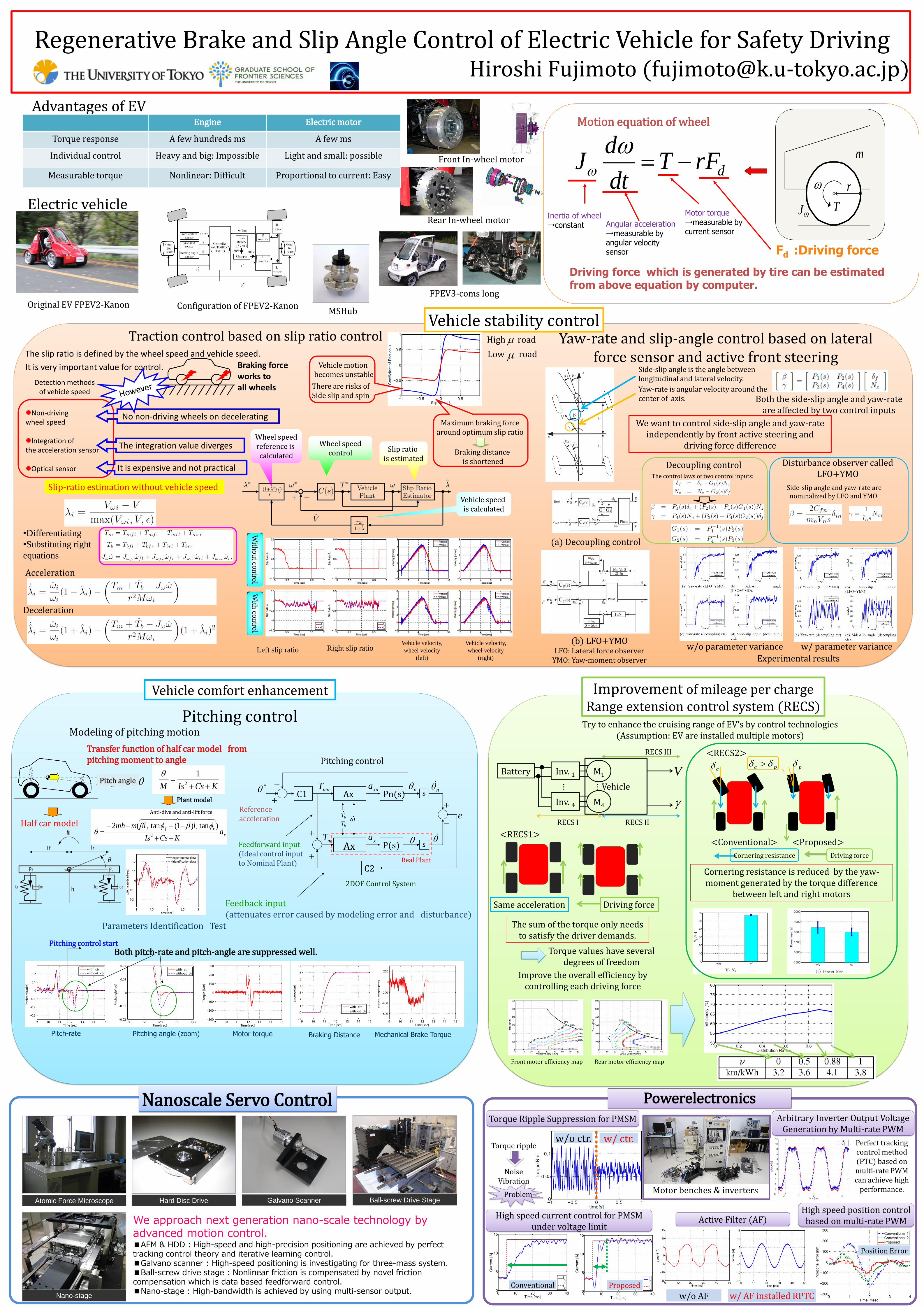
Advantages of EV
Original EV FPEV2-Kanon
Front In-wheel motor
Rear In-wheel motor
Configuration of FPEV2-Kanon
Vehicle stability control
Transfer function of half car model from pitching moment to angle
KCsIsM
2
1
Half car model x
rrffa
KCsIs
llmmh
2
)tan)1(tan(2
Parameters Identification Test
Plant model
Anti-dive and anti-lift force
Pitch angle
2DOF Control System
Real Plant
Ax
Ax Pn(s)
P(s)
s
s
C2
C1
xa
xna n n
mnT
mT
bT̂
bT e
*
Feedforward input (Ideal control input to Nominal Plant)
Feedback input (attenuates error caused by modeling error and disturbance)
Reference acceleration
Pitching control
Modeling of pitching motion
Pitch-rate Pitching angle (zoom) Motor torque
Both pitch-rate and pitch-angle are suppressed well. Pitching control start
Braking Distance
Vehicle comfort enhancement
Engine Electric motor
Torque response A few hundreds ms A few ms
Individual control Heavy and big: Impossible Light and small: possible
Measurable torque Nonlinear: Difficult Proportional to current: Easy
Electric vehicle
Improvement of mileage per charge Range extension control system (RECS)
Yaw-rate and slip-angle control based on lateral force sensor and active front steering
T
r
J
m
drFTdt
dJ
Motion equation of wheel
Driving force which is generated by tire can be estimated from above equation by computer.
Fd :Driving force
Angular acceleration →measurable by angular velocity sensor
Motor torque →measurable by current sensor
Inertia of wheel →constant
Non-driving wheel speed
Integration of the acceleration sensor
Optical sensor
Detection methods of vehicle speed
Braking force works to all wheels
No non-driving wheels on decelerating
The integration value diverges
It is expensive and not practical
Slip-ratio estimation without vehicle speed
Traction control based on slip ratio control
•Differentiating
•Substituting right
equations
Acceleration
Vehicle speed is calculated
Wheel speed reference is calculated
Wheel speed control Slip ratio
is estimated
Vehicle motion becomes unstable
There are risks of Side slip and spin
Maximum braking force around optimum slip ratio
Braking distance is shortened
Left slip ratio Right slip ratio
With
ou
t con
trol
With
con
trol
Vehicle velocity,
wheel velocity
(left)
Vehicle velocity,
wheel velocity
(right)
Deceleration
The slip ratio is defined by the wheel speed and vehicle speed.
It is very important value for control.
Experimental results
w/o parameter variance w/ parameter variance
(a) Decoupling control
(b) LFO+YMO LFO: Lateral force observer
YMO: Yaw-moment observer
Side-slip angle is the angle between longitudinal and lateral velocity.
Yaw-rate is angular velocity around the center of axis. Both the side-slip angle and yaw-rate
are affected by two control inputs
We want to control side-slip angle and yaw-rate independently by front active steering and
driving force difference
Decoupling control Disturbance observer called LFO+YMO The control laws of two control inputs:
Side-slip angle and yaw-rate are nominalized by LFO and YMO
Try to enhance the cruising range of EV’s by control technologies (Assumption: EV are installed multiple motors)
Battery Inv. 1
Inv. 4
M1
M4
…
… Vehicle
V
RECS I RECS II
RECS III
Same acceleration Driving force
<RECS1>
<RECS2>
Front motor efficiency map Rear motor efficiency map
Cornering resistance Driving force
<Conventional> <Proposed>
c pc p
The sum of the torque only needs to satisfy the driver demands.
Torque values have several degrees of freedom
Improve the overall efficiency by controlling each driving force
Cornering resistance is reduced by the yaw-moment generated by the torque difference
between left and right motors
FPEV3-coms long
MSHub
Pitching control
Atomic Force Microscope
Nano-stage
Hard Disc Drive Galvano Scanner Ball-screw Drive Stage
We approach next generation nano-scale technology by advanced motion control. ■AFM & HDD : High-speed and high-precision positioning are achieved by perfect tracking control theory and iterative learning control. ■Galvano scanner : High-speed positioning is investigating for three-mass system. ■Ball-screw drive stage : Nonlinear friction is compensated by novel friction compensation which is data based feedforward control. ■Nano-stage : High-bandwidth is achieved by using multi-sensor output.
Position Error
Conventional Proposed
w/ ctr. w/o ctr.
High speed current control for PMSM under voltage limit
Torque Ripple Suppression for PMSM
Motor benches & inverters
Powerelectronics
Torque ripple
Noise
Vibration
Problem
Arbitrary Inverter Output Voltage Generation by Multi-rate PWM
Perfect tracking control method (PTC) based on multi-rate PWM can achieve high
performance.
w/ AF installed RPTC w/o AF
Active Filter (AF) High speed position control
based on multi-rate PWM
Nanoscale Servo Control
Regenerative Brake and Slip Angle Control of Electric Vehicle for Safety Driving Hiroshi Fujimoto ([email protected])
High road
Low road