Embed Size (px)
Citation preview

Join us in Houston October 4-7, for the 2010 ASME Gas Turbine Users Symposium.
The 2010 GTUS program will build on the success of past years with an excitingslate of topics for the gas turbine user, consultant and manufacturer, according to ThomEldridge, 2010 GTUS Chair.
A new element of the 2010 program is a 2-part tutorial on coatings, their application,uses, materials, processes and serviceability. The program will again include atremendously popular session featuring selected, application-oriented technical papersfrom ASME Turbo Expo. A full-day, 3-part tutorial on the Introduction to Gas Turbineswill provide a comprehensive overview on the function, performance characteristics, and,in particular the typical operational issues for industrial gas turbines. Additional topics thisyear include remote monitoring, inlet conditioning and heat recovery steam generators.
With the current uncertainties in this recovering economy, the GTUS forumrepresents high ROI. It offers a practical and interactive opportunity to shareexperiences and challenges with other gas turbine users, manufacturers and consultants.
IGTI is also offering pre-symposium workshops on October 4, 2010 at the GeorgeR. Brown Convention Center:
n Gas Turbine Combined Cycle PrimerS. C. (John) Gülen, Principal Engineer, GE8:30 a.m. – 5:00 p.m.
n Basic Gas Turbine Metallurgy and Repair TechnologyLloyd Cooke & Doug Nagy, Liburdi Turbine Services; Warren Miglietti, Power Systems Mfg., LLC8:30 a.m. – 5:00 p.m.
Visit www.asmeconferences.org/gtus2010 for more details and to register.
Advance Registration Deadline is September 6, 2010. ASME members qualify for a reducedregistration fee. GTUS attendees have the option of upgrading their conference registration to include theTurbomachinery Symposium technical sessions for only $300.00 more. R
August 2010 Global Gas Turbine News 45
ATLANTA, GEORGIA USA /// ASME INTERNATIONAL GAS TURBINE INSTITUTE
Volume 50, No. 3 • August 2010
In this issueGTUS 2010
45View From the Chair& Calendar of Events
46As the Turbine Turns...
Focus on Fans
47Turbo Expo 2010
48-49IGTI Welcomes New
Board Member
49Young Engineer
Awards
49Performance Testingof Transonic Rotors
50-51ProfessionalDevelopment
51U.S. Navy Experience
with SSS (Syncro-Self-Shifting) Clutches
52-53Turbo Expo 2011
54New Technical
Committee Chairs
54
Register Today forthe 2010 ASME Gas Turbine Users SymposiumCo-located with the 39th Turbomachinery Symposium
GTUS RegistrationIncludes:
n Admission to all ASME GTUS sessions
n Free access to the39th TurbomachinerySymposium (T39)exhibit floor
n Complimentary T39 lunches and evening meals
n GTUS only networking dinnerand facility tour
n Invitation to the T39welcome address
n GTUS proceedings CD
n With upgrade fee,delegates also have admission to all T39 sessions

46 Global Gas Turbine News August 2010
A SUPPLEMENT TO MECHANICAL ENGINEERING MAGAZINE
NOVEMBER 22-26, 2010Gas Turbine Technology for Operations & Maintenance Engineers CourseCranfield University, UKFor more information, visit: http://www.cranfield.ac.uk/soe/shortcourses/gte/page4579.jsp
FEBRUARY 13-16, 2011The 1st Middle East Turbomachinery Symposium (METS)Sheraton Resort and Convention Center | Doha, QatarUnder the primary sponsorship of Qatar Petroleum, METS will be closely modeled after Texas A&M TurboLab’s Turbomachinery Symposium that has been held in Texas since 1971. For more information, visit:http://middleeastturbo.tamu.edu/
FEBRUARY 21-25, 2011Southwest Research Institute Training WeekSWRI | San Antonio, TX USAOffers hands-on training by industry experts.
JUNE 6-10, 2011ASME Turbo Expo 2011Vancouver Convention & Exhibition Centre | Vancouver, British Columbia, CanadaIGTI’s flagship event comprises a major gas turbine conference and exhibition. www.turboexpo.org
AUGUST 1-3, 201147th AIAA/ASME/SAE/ASEE Joint Propulsion Conference & Exhibit San Diego Convention Center | San Diego, CAwww.aiaa.org
JUNE 11-15, 2012ASME Turbo Expo 2012Bella Center | Copenhagen, DenmarkIGTI’s flagship event comprises a major gas turbine conference and exhibition.
OCTOBER 4, 2010ASME Gas Turbine Users Symposium (GTUS) WorkshopsCo-located with 39th Turbomachinery SymposiumGeorge R. Brown Convention Center | Houston, TX USA
• NEW - Gas Turbine Combined Cycle PrimerS. C. (John) Gülen, Principal Engineer, GE
• Basic Gas Turbine Metallurgy and Repair TechnologyLloyd Cooke & Doug Nagy, Liburdi Turbine Services; WarrenMiglietti, Power Systems Mfg., LLC
OCTOBER 4-7, 2010ASME Gas Turbine Users Symposium (GTUS)Co-located with 39th Turbomachinery Symposium George R. Brown Convention Center | Houston, TX USA
With its focus on gas turbine drivers, the GTUS program willcomplement the excellent technical content pertaining to rotatingequipment offered at the Turbomachinery Symposium.
OCTOBER 27-28, 2010IGTC-105th International Gas Turbine Conference Conrad Hotel | Brussels, Belgium
Organized by the European Turbine Network, the program will focuson the future of gas turbine (GT) technology from a users', a research,and a political point of view. It will also explore the market outlook andthe role played today by gas turbines in the international energy policymix as well as for the decades to come.http://www.etn-gasturbine.eu/page18052315.aspx
CALENDAR OF EVENTS
View From The ChairBy Ron S. Bunker, Ph.D., Chairman of the IGTI Board of Directors
Ron is a Principal Engineer in the Energy & Propulsion Technology Labs of the GE Global ResearchCenter in Niskayuna, New York. [email protected].
Welcome back to the Global Gas Turbine News(GGTN), the quarterly news and events letter of theASME International Gas Turbine Institute. First,looking back over my own journey of the last five years,I would like to thank our incredible and dedi cated IGTIstaff, as well as all of the technical communityvolunteers, for making our premier Turbo Expo eventsuch a success through good times and hard times. Wehave just completed a record breaking TE2010 inGlasgow despite the slow pace of recent economicrecovery (986 technical papers, a 7.5% increase overTE08 Berlin). This speaks volumes to the vitality andnecessity of the gas turbine and turbo machinery sectorglobally, and should emphasize to us all the importanceand impact of what we do as a technical group.
I recently viewed a lecture by Prof. Nate Lewis(CalTech), which was part of the “Jet Propulsion Labsvon Kármán Lecture Series” of February, 2008(http://nsl.caltech.edu/energy.html). This lecture sum -marized our current global energy consumption ratesand carbon emissions, and presented several projectionswith various optimistic or pessimistic assumptions to theyear 2050. By Nate’s reckoning the next forty years willeither make or break humans as a species. It is quite easyto come away from his simple yet logical predictions thatwe are doomed no matter what we do. The only path tosurvival that he proposes is one in which the worldimmediately builds up a solar energy usage capability,starting now (or rather in 2008), at the rate of somethinglike one million homes per day, setting aside issues like
energy storage. Well, ‘daunting’ was the word often usedin his lecture to be sure. However, though we are nowemitting historically record levels of carbon, we do notactually yet know, nor can we predict, the outcome of these higher ppm levels. This isthe one bright spot, if we can call it that, to encourage us to find solutions.
While Nate never mentions gas turbines, one of the big target areas he highlights forimmediate action is higher efficiency power / energy production, as well as lowerconsumer use. Gas turbines, steam turbines, and associated turbomachinery systems arekey here, especially as many employ natural gas, the lowest carbon emitter of thecurrent fossil fuels in common use. Nate takes note of wind turbines as the fastestgrowing and most cost effective means of increasing energy from renewables, at least asa small piece of the overall solution. Solar is by his estimation though the onlysustainable resource capable of solving our dilemma.
So, what can IGTI do today and in the critical next 10 to 20 years to help meet thischallenge? As many of you saw in Glasgow, we are working to expand our influenceand apply our expertise not only to increased energy efficiency from gas and steamturbines, but also wind turbines. The IGTI technical community has vast experiencethat can be applied in this energy field. It does not stop there. In the TE2011 inVancouver, technical sessions will begin around the area of combined solar-turbinepower cycles and installations. In fact, all aspects of energy exploration, conversion,and delivery that involve rotating turbomachines can benefit from our expertise andaccumulated knowledge. As an integral part of ASME, IGTI has a large role to play inASME’s Grand Energy Challenge (http://strategy.asme.org/energy.cfm). The IGTIBoard of Directors is seeking to expand our involvement and influence in thischallenge, both on the technical and political fronts. This may take the form of jointcooperative efforts with other ASME divisions and other societies / organizations, anexpanded Turbo Expo event, or additional IGTI events. Your contributions areabsolutely necessary to the success of whatever path(s) we take. I invite yoursuggestions and commentary at any time, and that includes contributed articles to thisGGTN publication. R

A SUPPLEMENT TO MECHANICAL ENGINEERING MAGAZINE
When jet-engined commercial flights firststarted in the 1950’s, aircraft were powered byturbojets – jet engines in which all thrust wasprovided by gases that went through the enginefrom inlet to exhaust nozzle, exiting in a singlehigh velocity jet.
Nowadays, almost all commercial aircraft are poweredby turbofan jet engines, so-named for a ducted front-mounted fan. Air drawn into the fan is divided into thatwhich flows out of the fan into the jet engine itself and theremainder that bypasses the engine. The lower velocitybypassed air and the higher velocity engine air combinedownstream to produce thrust with a larger mass flow atan average velocity lower than the high velocity jet flow.
With a large frontal area, the commercial aircraftturbofan is designed to produce peak thrust at takeoff,with most of the thrust produced by air drawn in by thefan that bypasses the jet engine core itself. Bypass ratios, -the mass of fan air bypassed for every unit mass of airthrough the engine – can be as high as 8.4:1, as inGeneral Electric’s 100,000 pound thrust GE90 engine.
The addition of a fan to a jet engine was firstproposed by Frank Whittle (one of the inventors of thejet engine) in a 1930 British patent. He called it a thrustaugmenter, because its addition does increase thrust andreduce fuel consumption (that is, has a lower thrustspecific fuel consumption (TSFC).
For subsonic flight, the propulsive efficiency, p, of aturbofan is also higher than that of a turbojet. Thisefficiency is defined as the useful propulsive power (theproduct of thrust and flight velocity, Vo) divided by jetpower (rate of change of the kinetic energy of gasesthrough the engine). This simplifies to [1]
Fig. 1
where Ve is a suitable average of the lower velocitybypass air and the higher velocity jet exhaust.Equation (1) shows that a turbojet engine with a highvalue of Ve/Vo has low propulsive efficiency, while aturbofan engine with low values has a correspondinghigh propulsion efficiency.
Since Ve in Equ. (1) is largely determined by bypassflow in a high bypass engine the fan pressure ratio (whichcould be 1.6 for a bypass ratio of 8:1) is the keyparameter. Lowering it to decrease Ve and increase pmeans increasing the bypass ratio.
New fan technology that has been developed by Prattand Whitney to increase bypass ratios to 11:l, using a gearbox to reduce fan speed and increase fan diameters. Thenet result is a large reduction in engine noise and as
Featured Column: As the Turbine Turns...
Focus on FansBy Dr. Lee S. Langston, Professor Emeritus of Engineering, University of Connecticut
Langston is a former editor of the ASME Journal of Engineering for Gas Turbines and Power and hasserved on the IGTI Board of Directors as both Chair and Treasurer.
much as a 16 percent improvement in fuel consumption (lower TSFC). Right nowP&W geared turbofan engines are being designed, developed and tested in the 18,000 –30,000 pound thrust range, which represents the biggest and most lucrative part ofcommercial aviation engine market.[2]
Some have scoffed at the use of a gear box for the fan. At IGTI’s TURBO EXPO’05 in Reno, during the keynote session, the president of Pratt & Whitney reported onprogress with the geared turbofan. During the keynote discussion period, retired CEOsfrom GE Aircraft Engines and Rolls-Royce both stated that based on their experiencesuch gear systems were to be avoided.
Recently, I was given a tour of P&W’s gear facilities in Middletown Connecticut byMichael McCune, who is the manager of their fan drive gear systems. The company hasbeen developing the fan gear box over a period of twenty years, involving a seriouscommitment of research, design and gear rig testing. The company has a long history ofgear box experience associated with their very popular turboprop gas turbines at Pratt &Whitney Canada.
Field tests have conclusively shown that the geared turbofan has a much lower levelof noise. Currently, some airlines have as much as 35-60 percent of their operating costsin jet fuel use. If the geared fan engine does indeed significantly reduce fuel use, thisimprovement in fan performance will be hard for the competition to beat.
Another way to improve fan performance is to change the pitch of fan blades,during an aircraft flight cycle. For instance, with propeller driven planes, controllablepitch propellers have been in use since the 1920s. During the 1990s jet enginecompanies tested variable pitch turbofans, but the variable pitch mechanisms usedproved to be heavy, bulky and difficult to control.
Recently, Rotating Composite Technologies (RCT), a small firm in Kensington,Conn. has come up with a unique patented design for the variable pitch fan that promisesto overcome the deficiencies of those tested in the 1990s[3]. As I write this, two papers onit are scheduled to be presented at our June 14-18, 2010 Turbo Expo in Glasgow. One byJohn Violette and Eric Loos[4] describes the new RCT variable pitch fan design. Thesecond paper by Robert Mazzawy[5] compares a conventional engine design with one thathas the RCT variable pitch fan. Both engines were sized to deliver 30,000 pounds thrustat the operating point. The Mazzawy study shows that an 11 to 16 percent fuel burnimprovement for the RCT variable pitch fan design, covering a range of flight profiles.
Stay tuned to see if geared and variable pitch fans willmove into the jet engine market, to bring about doubledigit improvements in airline fuel efficiency! R
References1. Mattingly, J.D., 1996, Elements of Gas Turbine Propulsion,McGraw-Hill, P. 27.
2. Langston, L.S., 2010, “Air Race”, Mechanical EngineeringMagazine, May, pp. 34-38.
3. Langston, L.S., 2009, “Fitting a Pitch”, MechanicalEngineering Magazine, December, pp. 38-42.
4. Violette, J.A. and Loos, E.S., 2010, “MechanicalDesign of a Variable Pitch Fan for TurbofanEngines”, Proc. of ASME TURBO EXPO, June14-18, 2010, Glasgow, GT2010-22969.
5. Mazzawy, R.S., 2010, “Performance Studyfor Benefits of Variable Pitch CompositeFan”, Proc. of ASMETURBO EXPO, June14-18, 2010, Glasgow, GT2010-22148.
August 2010 Global Gas Turbine News
RCT Variable Pitch Turbofan
48 Global Gas Turbine News August 2010
A SUPPLEMENT TO MECHANICAL ENGINEERING MAGAZINE
Thank YouTurbo Expo
2010Sponsors
GE
Pratt & Whitney
Rolls-Royce
ANSYS
Oxsensis
NUMECA
Parker Hannifin
Solar Turbines
Siemens
Flowmaster
SouthwestResearch Institute
ALSTOM
Glasgow City
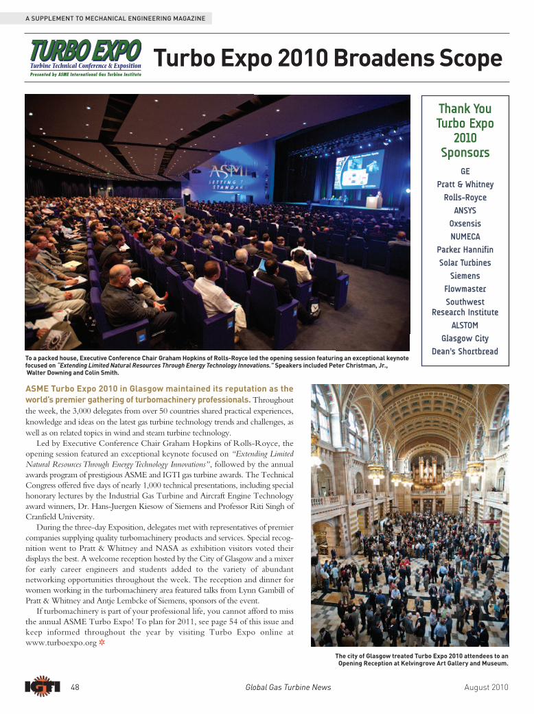
Dean’s ShortbreadTo a packed house, Executive Conference Chair Graham Hopkins of Rolls-Royce led the opening session featuring an exceptional keynotefocused on “Extending Limited Natural Resources Through Energy Technology Innovations.” Speakers included Peter Christman, Jr.,Walter Downing and Colin Smith.
The city of Glasgow treated Turbo Expo 2010 attendees to anOpening Reception at Kelvingrove Art Gallery and Museum.
Turbo Expo 2010 Broadens ScopePresented by ASME International Gas Turbine Institute
ASME Turbo Expo 2010 in Glasgow maintained its reputation as theworld’s premier gathering of turbomachinery professionals. Throughoutthe week, the 3,000 delegates from over 50 countries shared practical experiences,knowledge and ideas on the latest gas turbine technology trends and challenges, aswell as on related topics in wind and steam turbine technology.
Led by Executive Conference Chair Graham Hopkins of Rolls-Royce, theopening session featured an excep tional keynote focused on “Extending LimitedNatural Resources Through Energy Technology Innovations”, followed by the annualawards program of prestigious ASME and IGTI gas turbine awards. The TechnicalCongress offered five days of nearly 1,000 technical presentations, including specialhonorary lectures by the Industrial Gas Turbine and Aircraft Engine Technologyaward winners, Dr. Hans-Juergen Kiesow of Siemens and Professor Riti Singh ofCranfield University.
During the three-day Exposition, delegates met with representatives of premiercompanies supplying quality turbomachinery products and services. Special recog -nition went to Pratt & Whitney and NASA as exhibition visitors voted theirdisplays the best. A welcome reception hosted by the City of Glasgow and a mixerfor early career engineers and students added to the variety of abundantnetworking opportunities throughout the week. The reception and dinner forwomen working in the turbomachinery area featured talks from Lynn Gambill ofPratt & Whitney and Antje Lembcke of Siemens, sponsors of the event.
If turbomachinery is part of your professional life, you cannot afford to missthe annual ASME Turbo Expo! To plan for 2011, see page 54 of this issue andkeep informed throughout the year by visiting Turbo Expo online atwww.turboexpo.org R
August 2010 Global Gas Turbine News 49
A SUPPLEMENT TO MECHANICAL ENGINEERING MAGAZINE
The Reception and Dinner for Women Working in the Turbomachinery Area featuredtalks from Lynn Gambill of Pratt & Whitney and Antje Lembcke of Siemens.
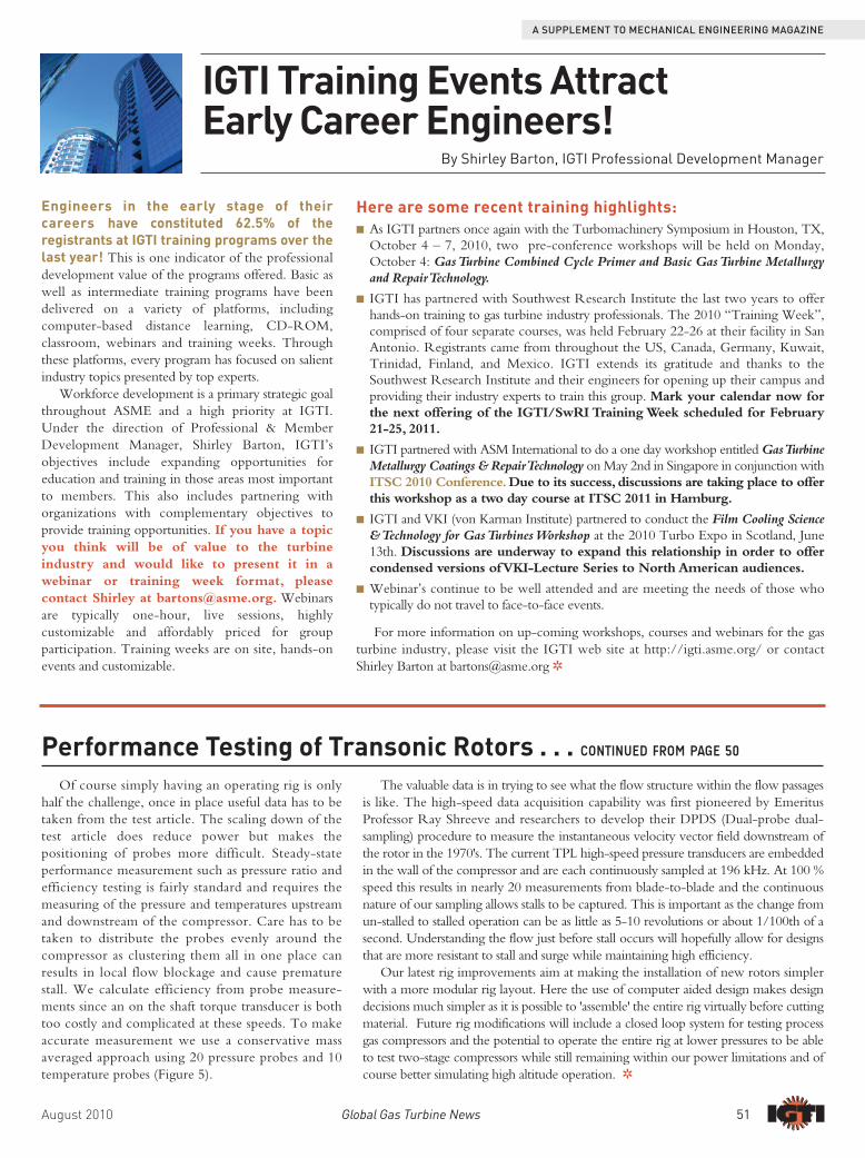
The Expo showcased cutting edge technologies from major OEMs.
Best Booth - Large Display - Pratt & Whitney Best Booth - Small Display - NASA
IGTI is pleased to announceour newest Board member,Dr. Seung Jin Song, Professorof Mechanical and AerospaceEngineering at Seoul NationalUniversity in South Korea.
Song earned his Sc.D. in Aeronautics & Astronauticsat MIT. Prior to his current position, he was a researchassistant, assistant professor, and visiting professor atseveral different universities.
Song specializes in aerodynamics and fluid structureinteractions in turbomachinery, power plant systemdesign and performance analysis, and stability ofrefrigeration systems. He has been involved withASME Turbo Expo since 1996 and has achieved avariety of honors throughout his career, including theASME Melville Medal in 2003. He is a member ofboth ASME and the Korean Society of MechanicalEngineers and has also served as an editor of varioustechnical journals. R
IGTI Welcomes New Board Member
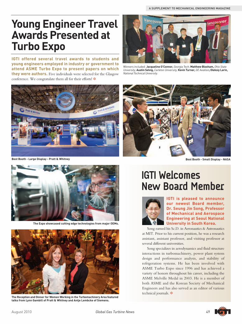
IGTI offered several travel awards to students andyoung engineers employed in industry or government toattend ASME Turbo Expo to present papers on whichthey were authors. Five individuals were selected for the Glasgowconference. We congratulate them all for their efforts! R
Winners included: Jacqueline O’Connor, Georgia Tech; Matthew Bloxham, Ohio StateUniversity; Austin Selvig, Carleton University; Kevin Turner, GE Aviation; Oleksiy Larin,National Technical University.
Young Engineer TravelAwards Presented atTurbo Expo

50 Global Gas Turbine News August 2010
A SUPPLEMENT TO MECHANICAL ENGINEERING MAGAZINE
Performance Testing of Transonic RotorsBy Anthony J. Gannon and Garth V. Hobson
A driving force behind the improvement found in high-speedcompressor fans has been the advent of computer simulations. Ofcourse there is still a need to test these fans and in some cases be able to evaluate thecomputer codes against accurate experimental data. Here I hope to share some of thechallenges and solutions found in the testing these compressor fans.
At the Turbopropulsion laboratory (TPL) at the Naval Postgraduate School (NPS)the research and testing of high-speed compressors also affords students the opportunityto work with these machines. With these types of machines supersonic flows are presentand there is no longer the ability to make the assumption of incompressible flow as withmost fan test rigs in educational environments. While education is a driving force of NPSthe test compressors are used for current research with students completing masters thesesusing data collected within the laboratory. The TPL test facility focused on here, thetransonic compressor rig (TCR) shown in Figure 1 is capable of delivering 337kW (450hp) at 30 000 rpm. What is remarkable is that this power is absorbed by an 279 mm (11")rotor weighing around 4.5 kg (10 lbs). Of course when involved in testing of such highlystressed machines, on occasion failure does occur; Figure 2.
In an ideal situation experimental work is best done on full scale devices butobviously cost and practical constraints mean this is not usually possible. Instead oneneeds to isolate the most influential variables and try to design experiments that capturethese. In the case of high-speed compressors the Mach number is one of the mostimportant parameters. In order to limit power consumption in a test machine thesimplest change is simply to scale down the machine. If the tip speed of the blades is tobe kept the same to ensure Mach number matching with operational compressors therotational speed needs to be increased proportionally. Typically our test compressorsrun with tip Mach numbers of approximately 1.5.
A second concept to reduce the power consumption of the machine once youhave scaled it down is to throttle the flow before the rotor rather than after it. As ahigh-speed rotor compresses the incoming air by around 1.4-1.6 times the air leavingit is appreciably denser than that coming in. If one throttles upstream of the rotor theexhaust air leaves the machine at atmospheric pressure which means that the incomingair is below atmospheric pressure. Throttling after the machine means one is suckingin atmospheric air and the mass-flow through the machine is approximately 30%higher with a near proportional increase in the power consumption. In the case ofaviation engines this reduction in density is similar to flying at high altitude. For sealevel based gas-turbines such as in ships or power stations the flow change fromlaminar to turbulent over the blade will occurs sooner than at altitude, however theseeffects can be accounted for empirically. With upstream throttling care has to be takento provide long enough ducting ahead of the test compressor to present as uniform aspossible flow after the flow rate measuring nozzle.
Another challenge is bearing choice and the proper functioning of the associatedlubrication systems. Rotating test rigs are by there nature unique devices and sooperation of them is a continuous learning process. In the last decade the emergenceon affordable ceramic ball bearings has been a major advantage. They allow operation
at much higher rotating speeds and operatingtemperatures. Bearing cooling and lubrication is stillneeded and this is performed using an oil mist coolingsystem. In the TPL rig there are four bearing sets andfour oil mist coolers with redundancy built in byallowing each oil mist cooler to service two bearing sets(Figure 3). In this way if one oil mister fails no bearingare left without lubrication. A bearing arrangementsimilar to a milling machine spindle is used with the rearbearing pair held in place by flexure arms that areinstrumented to measure the net force forward orrearwards on the shaft while the front bearing pair isallowed to float. The reason for this is that the shaftlengthens during operation due to temperature increaseand load and thus one bearing pair needs to float. Theaxial forward pull of the test rotor is counteracted by apneumatic balance piston at the rear of the shaft and theforce adjusted until the net axial force on the shaft isclose to zero. The most amazing aspect of this rig is thatit was designed on the late 60's by the late ProfessorMike Vavra and the rig is still state-of-the-art today.
There was some concern about the ability of ceramicball bearings to handle the shock loads of compressorstall and surge. Here the compressor applies large cyclicforces to the rig via the rig as it stall and un-stalls duringa surge cycle. During an experiment it is routine todrive the compressor into surge and observe when surgeoccurs and what is required to recover from a surge.Our experience has shown that the bearings canwithstand about a dozen surge cycles.
A further operational consideration is the need tooperate with very small tip clearances. A scaled downcompressor operating at high-speed tends to growradially and rubbing between the casing and blade tips isnormal. Figure 4 shows the abradable material whichallows operation at very small tip gaps withoutdamaging the rotor. This material is baked into a trenchabove the rotor and needs to abrade without sanding thetips of the rotor. We have settled with a machinablerubberized material and grooved the bottom of thetrench to improve the adhesion to the casing.
...CONTINUED ON PAGE 51
Figure 1.Test Fan and Stator.
Figure 2.Compressor Rotor Failure.
Figure 3.Drive Turbine Housing andOil-Mist Cooling System.
Figure 4.High-speed Pressure Probes
and Abradable Strip.
Figure 5.Instrumentation setup.
August 2010 Global Gas Turbine News 51
A SUPPLEMENT TO MECHANICAL ENGINEERING MAGAZINE
Here are some recent training highlights:n As IGTI partners once again with the Turbomachinery Symposium in Houston, TX,October 4 – 7, 2010, two pre-conference workshops will be held on Monday,October 4: Gas Turbine Combined Cycle Primer and Basic Gas Turbine Metallurgyand Repair Technology.
n IGTI has partnered with Southwest Research Institute the last two years to offerhands-on training to gas turbine industry professionals. The 2010 “Training Week”,comprised of four separate courses, was held February 22-26 at their facility in SanAntonio. Registrants came from throughout the US, Canada, Germany, Kuwait,Trinidad, Finland, and Mexico. IGTI extends its gratitude and thanks to theSouthwest Research Institute and their engineers for opening up their campus andproviding their industry experts to train this group. Mark your calendar now forthe next offering of the IGTI/SwRI Training Week scheduled for February21-25, 2011.
n IGTI partnered with ASM International to do a one day workshop entitled Gas TurbineMetallurgy Coatings & Repair Technology on May 2nd in Singapore in conjunction withITSC 2010 Conference.Due to its success, discussions are taking place to offerthis workshop as a two day course at ITSC 2011 in Hamburg.
n IGTI and VKI (von Karman Institute) partnered to conduct the Film Cooling Science& Technology for Gas Turbines Workshop at the 2010 Turbo Expo in Scotland, June13th. Discussions are underway to expand this relationship in order to offercondensed versions of VKI-Lecture Series to North American audiences.
n Webinar’s continue to be well attended and are meeting the needs of those whotypically do not travel to face-to-face events.
For more information on up-coming workshops, courses and webinars for the gasturbine industry, please visit the IGTI web site at http://igti.asme.org/ or contactShirley Barton at [email protected] R
Engineers in the early stage of theircareers have constituted 62.5% of theregistrants at IGTI training programs over thelast year! This is one indicator of the professionaldevelopment value of the programs offered. Basic aswell as intermediate training programs have beendelivered on a variety of platforms, includingcomputer-based distance learning, CD-ROM,classroom, webinars and training weeks. Throughthese platforms, every program has focused on salientindustry topics presented by top experts.
Workforce development is a primary strategic goalthroughout ASME and a high priority at IGTI.Under the direction of Professional & MemberDevelopment Manager, Shirley Barton, IGTI’sobjectives include expanding opportunities foreducation and training in those areas most importantto members. This also includes partnering withorganizations with complementary objectives toprovide training opportunities. If you have a topicyou think will be of value to the turbineindustry and would like to present it in awebinar or training week format, pleasecontact Shirley at [email protected]. Webinarsare typically one-hour, live sessions, highlycustomizable and affordably priced for groupparticipation. Training weeks are on site, hands-onevents and customizable.
IGTI Training Events Attract Early Career Engineers!
By Shirley Barton, IGTI Professional Development Manager
Performance Testing of Transonic Rotors . . . CONTINUED FROM PAGE 50Of course simply having an operating rig is only
half the challenge, once in place useful data has to betaken from the test article. The scaling down of thetest article does reduce power but makes thepositioning of probes more difficult. Steady-stateperformance measurement such as pressure ratio andefficiency testing is fairly standard and requires themeasuring of the pressure and temperatures upstreamand downstream of the com pressor. Care has to betaken to distribute the probes evenly around thecompressor as clustering them all in one place canresults in local flow blockage and cause prematurestall. We calculate efficiency from probe measure -ments since an on the shaft torque transducer is bothtoo costly and compli cated at these speeds. To makeaccurate measurement we use a conservative massaveraged approach using 20 pressure probes and 10temperature probes (Figure 5).
The valuable data is in trying to see what the flow structure within the flow passagesis like. The high-speed data acquisition capability was first pioneered by EmeritusProfessor Ray Shreeve and researchers to develop their DPDS (Dual-probe dual-sampling) procedure to measure the instantaneous velocity vector field downstream ofthe rotor in the 1970's. The current TPL high-speed pressure transducers are embeddedin the wall of the compressor and are each continuously sampled at 196 kHz. At 100 %speed this results in nearly 20 measurements from blade-to-blade and the continuousnature of our sampling allows stalls to be captured. This is important as the change fromun-stalled to stalled operation can be as little as 5-10 revolutions or about 1/100th of asecond. Understanding the flow just before stall occurs will hopefully allow for designsthat are more resistant to stall and surge while maintaining high efficiency.
Our latest rig improvements aim at making the installation of new rotors simplerwith a more modular rig layout. Here the use of computer aided design makes designdecisions much simpler as it is possible to 'assemble' the entire rig virtually before cuttingmaterial. Future rig modifications will include a closed loop system for testing processgas compressors and the potential to operate the entire rig at lower pressures to be ableto test two-stage compressors while still remaining within our power limitations and ofcourse better simulating high altitude operation. R
52 Global Gas Turbine News August 2010
A SUPPLEMENT TO MECHANICAL ENGINEERING MAGAZINE
In the late 1940’s and early 1950’s, variousnavies began to consider the use of aero-derivative gas turbines for marine propul sionbecause the gas turbine was seen as acompact, high-power-to-weight ratio enginethat would reduce engine room space, reduceship size or increase space for arma ments,etc., reduce the time required to get a shipunderway, and potentially reduce man powerrequirements. As the gas turbine, unlike the steamturbine, was not particularly efficient at part load, it wasseen that multiple engines would be needed perpropeller shaft and a reliable means to connect eachengine to a propulsion system/shaft line at rest and atspeed would be needed.
Both the British Royal Navy and U.S. Navyexplored the addition of cruising steam and latercruising gas turbines for steam turbine main propulsionplants in the late 1950’s and early 1960’s; and the firstSSS (Synchro-Self-Shifting) clutches were supplied forthe Y-100 marine main propulsion plant for the BritishRoyal Navy in 1958. The successful operation of thisSSS clutch paved the way for future consideration fornaval gas turbine applications.
Recognizing that a combined propulsion machineryunit with gas turbines for boost power would requirereliable propulsion clutches to disconnect the engineswhen not in use, the U. S. Navy initiated an evaluation ofvarious means of disconnecting a gas turbine engine andultimately selected and tested 7500 hp capacity clutchdesigns including a forced synchronizing friction/tooth clutch and overrunning clutches. After consider abletesting and evaluation, the clutch designs were consideredacceptable for high-power propulsion with reasonablerequirements for differential speed at engagement.
In 1968, the U. S. Navy decided to proceed with itsfirst, combined all gas turbine powered (COGAG) navalship class, the Spruance Class Destroyers, and the mainreduction gearbox manufacturer supplied forcedsynchronizing/dental tooth clutches. In the late 1960’s,the U. S. Navy initiated the construction of a largenumber of single-shaft ships, the Admiral Perry Class(FFG) Frigates, and SSS clutches were recommendedand supplied by the main reduction gearbox manu -facturer who had gained valuable experience with SSSclutches on U. S. Coast Guard High Endurance Cutters.
In 1980, SSS clutches were chosen for the U. S. NavyTiconderoga Class Cruisers (CG-47 Class), and the mainreduction gearboxes were the same as the Spruance ClassDestroyers except SSS clutches were chosen by the U. S.
Navy instead of forced synchronizing/dental tooth clutches because of operatingexperience problems on Spruance Class Destroyer clutches. Within ten years most ofthe Spruance Class clutches were retrofitted with SSS clutches. From the mid-1980’s allfuture U.S. Navy gas turbine propelled ships utilized SSS main propulsion clutches. SSSclutches were also being adopted for auxiliary drives as well.
SSS CLUTCH DESIGN & OPERATING PRINCIPLESThe SSS clutch is a freewheel-type, overrunning clutch which transmits torque
through concentric surface-hardened gear teeth. Unlike a servo-actuated toothcoupling which is difficult to shift into mesh at rest or at speed, phasing andengagement of the SSS clutch teeth at synchronous speed is accomplishedautomatically without any external controls and without possibility of error. Also,unlike a tooth coupling, disengagement of the clutch will occur whenever the inputslows down relative to the output without the need to maintain an unloaded turbinecondition for disengagement.
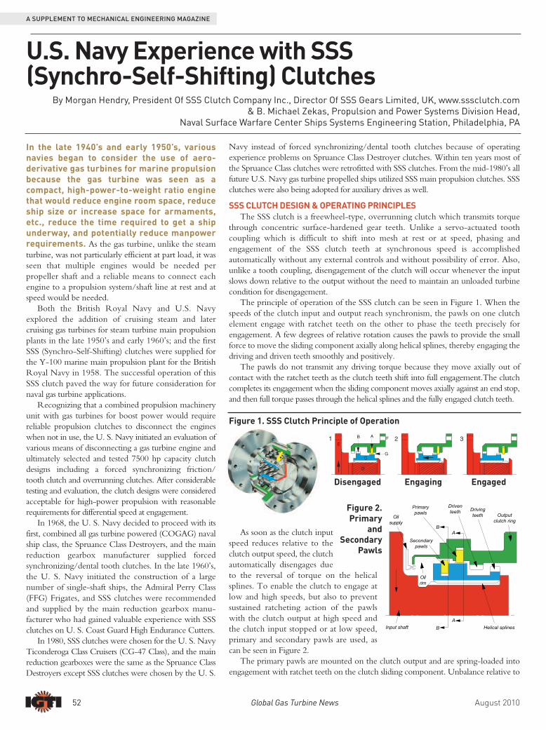
The principle of operation of the SSS clutch can be seen in Figure 1. When thespeeds of the clutch input and output reach synchronism, the pawls on one clutchelement engage with ratchet teeth on the other to phase the teeth precisely forengagement. A few degrees of relative rotation causes the pawls to provide the smallforce to move the sliding component axially along helical splines, thereby engaging thedriving and driven teeth smoothly and positively.
The pawls do not transmit any driving torque because they move axially out ofcontact with the ratchet teeth as the clutch teeth shift into full engagement.The clutchcompletes its engagement when the sliding component moves axially against an end stop,and then full torque passes through the helical splines and the fully engaged clutch teeth.
As soon as the clutch inputspeed reduces relative to theclutch output speed, the clutchautomatically disengages dueto the reversal of torque on the helicalsplines. To enable the clutch to engage atlow and high speeds, but also to preventsustained ratcheting action of the pawlswith the clutch output at high speed andthe clutch input stopped or at low speed,primary and secondary pawls are used, ascan be seen in Figure 2.
The primary pawls are mounted on the clutch output and are spring-loaded intoengagement with ratchet teeth on the clutch sliding component. Unbalance relative to
U.S. Navy Experience with SSS (Synchro-Self-Shifting) Clutches
By Morgan Hendry, President Of SSS Clutch Company Inc., Director Of SSS Gears Limited, UK, www.sssclutch.com& B. Michael Zekas, Propulsion and Power Systems Division Head,
Naval Surface Warfare Center Ships Systems Engineering Station, Philadelphia, PA
Figure 1. SSS Clutch Principle of Operation
Disengaged Engaging Engaged
Figure 2.Primary
andSecondary
Pawls
August 2010 Global Gas Turbine News 53
A SUPPLEMENT TO MECHANICAL ENGINEERING MAGAZINE
the pawl central pivot pin causes the primary pawls to retract from the ratchet teethdue to centrifugal force when the output exceeds a predetermined speed; typicallyabout 500 rpm.
The secondary pawls, which are mounted on the clutch input, usually the clutchsliding component, are used to engage the clutch in the high-speed range, which is tosay when the clutch input accelerates to the same speed as the output. When the inputrotates, unbalance relative to the pawl central pivot pin engages the pawl with theratchet teeth in the clutch output. However, when there is high differential speedbetween the pawls and ratchet teeth, the pawls skim on the oil within the clutchoutput. Therefore, both sets of pawls are inert when the clutch output is rotating athigh speed and the clutch input is at rest or at low speed, and both sets of pawls areseparated axially from their ratchet teeth when the clutch is engaged. Hence the pawlshave a very long life; in many cases they last the life of the ship.
ADDITIONAL SSS CLUTCH FEATURESIn addition to the basic SSS clutch design and operation, additional features are
available for high-power and/or high-speed applications. These features include an oildashpot inside the clutch, continuously supplied with oil from the lubrication system,to “cushion” clutch engagement under high relative acceleration conditions and toprevent disengagement under transient negative torque conditions. An additionalfeature is a relay clutch built within the main SSS clutch to enable SSS clutches totransmit high power yet keep the synchronizing mechanism (pawls and ratchets)within the clutch small and reliable. To suit various arrangement and operatingrequirements, optional features such as Manual Lock-Out, Servo Lock-Out, ServoLock-In, and a Lock-Out/Lock-In feature can also be provided.
MOUNTING ARRANGEMENTSSSS clutches are typically an in-line, flange mounted drive arrangement, or
mounted on the end of the gearbox input shaft that extends through the center of thehigh speed pinion (quill shaft mounting). For Combined Gas Turbine or Diesel(CODOG) or combined gas turbine and diesel (CODAG) gearboxes, the clutches aresometimes mounted in the intermediate shaft position as often one gas turbine andtwo diesel engines are used per reduction gear. The U.S. Navy and other navies havealso designed main reduction gears with electric motors for auxiliary or cruisepropulsion and gas turbines for boost power (CODELAG), and again the clutches aremounted in either configuration.
U.S. NAVAL MARINE EXPERIENCEThe U.S. Navy has nearly forty years of experience using SSS clutches in main
reduction gears of gas-turbine-driven ships and propulsion systems with combi -nations of gas turbines and diesel engines or electric motors, and in steam-turbinepropulsion plants for use with electric motor drives. Over 900 SSS clutches havebeen installed in fourteen different classes of U.S. Navy ships, with some havingbeen in service for over thirty years. SSS clutches have accumulated approximately15,278,000 hours of operation.
Clutch duty on U.S Navy ship Classes, each nominally rated at a 50,000 SHP, isconsidered to be more strenuous than the original design requirement due to theincreased operating time (and cycles) at high torque. The highest percentage of shipoperations is performed in a single engine driving / trail shaft mode (on twin shaftships) in order to minimize fuel usage and to maximize range. The end result isoperating at a higher torque (that exceeds full power torque) on the driving shaft. Fleetdata indicates that ships operate in this mode 68% of the time. Full power operation isperformed 10% of the time, and the remaining 22% is at the less than 50% power level.As the SSS clutches are “operating” whenever they are engaged or whenever they aredisengaged or overrunning (as would be the case with the off-line clutch when theship is in single engine propulsion mode) the average total number of clutch operatinghours could be up to 68% greater than total engine operating hours on any given ship.
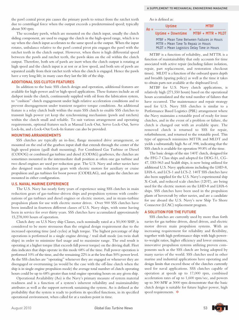
Operational Availability (Ao) is the Navy’s primary measure of system materialreadiness and is a function of a system’s inherent reliability and maintainabilityattributes as well as the support network sustaining the system. Ao is defined as theprobability that the system is ready to perform its specified functions, in its specifiedoperational environment, when called for at a random point in time.
Ao is defined as:
MTBF is a function of reliability, and MTTR is afunction of maintainability that only accounts for timeassociated with active repair (including failure isolation,repair, part replacement, and restoration checkouttimes). MLDT is a function of the onboard spares depthand breadth (sparing policy) as well as the time it takesto obtain parts not available at the shipboard level.
MTBF for U.S. Navy clutch applications, isrelatively high (271,550 hours) based on the operationalhours accumulated and the total number of failures thathave occurred. The maintenance and repair strategyused for U.S. Navy SSS clutches is similar to aPerformance Based Logistics (PBL) arrangement wherethe Navy maintains a rotatable pool of ready for issueclutches, and in the event of a problem or failure, theclutch is changed out with an available spare. Theremoved clutch is returned to SSS for repair,refurbishment, and returned to the rotatable pool. Thistype of approach minimizes MTTR and MLDT andyields a substantially high Ao of .998, indicating that theSSS clutch is available for operation 99.8% of the time.
The basic design of the size 140T clutch, designed forthe FFG-7 Class ships and adopted for DDG-51, CG-47, DD-963 and Sealift ships, is now being utilized foradditional U.S. Navy applications including the LHD-8,LHA-6, and LCS-1 and LCS-2. 140T SSS clutches havealso been supplied for the U.S. Navy’s experimental shipX-Craft, and reduced scale clutches (120T), are beingused for the electric motors on the LHD-8 and LHA-6ships. SSS clutches have been used in the propulsionplants of hovercraft by other navies, and are a candidatefor use aboard the U.S. Navy’s new Ship To ShoreConnector (LCAC) replacement program.
A SOLUTION FOR THE FUTURESSS clutches are currently used by more than forth
navies for gas turbine driven, diesel driven, and electricmotor driven main propulsion systems. With anincreasing requirement for reliability and flexibility,together with high performance ships with high power-to-weight ratios, higher efficiency and lower emissions,innovative propulsion systems utilizing proven com -ponents such as the SSS clutch are being adopted bymany navies of the world. SSS clutches used in othermarine and industrial applications have operating anddesign limits that exceed those of the clutches currentlyused for naval applications. SSS clutches capable ofoperation at speeds up to 17,000 rpm, combinedacceleration rates of up to 1,600 rpm/sec, and powersup to 300 MW at 3000 rpm demonstrate that the basicclutch design is suitable for future higher power, highspeed requirements. R
Uptime MTBFAo = ––––––––––––––––––––––––––––– = –––––––––––––––––––––––––––––
Uptime + Downtime MTBF + MTTR + MLDT
MTBF = Mean Time Between Failures in HoursMTTR = Mean Time To Repair in HoursMLDT = Mean Logistics Delay Time in Hours
Call for PapersASME Turbo Expo 2011Abstracts are due by September 6, 2010, and mustbe submitted online (plain text, 400 word limit) viathe IGTI Conference Web site at www.turboexpo.org.
The 2011 Publication Schedule:
n Abstract Submission - September 6, 2010n Draft Paper Due Date - November 8, 2010n Paper Reviews Complete – December 20, 2010n Author Notification of Paper Acceptance -
January 10, 2011n Submission of Final Paper – February 21, 2011n Final Paper Approval by Review Chair -
March 21, 2011
54 Global Gas Turbine News August 2010
A SUPPLEMENT TO MECHANICAL ENGINEERING MAGAZINE
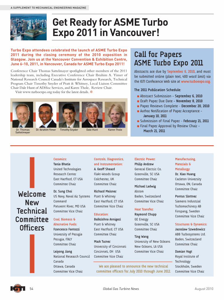
Get Ready for ASME TurboExpo 2011 in Vancouver!
Conference Chair Thomas Sattelmayer spotlighted other members of the 2011leadership team, including Executive Conference Chair Ibrahim A. Yimer ofNational Research Council Canada’s Institute for Aerospace Research, TechnicalProgram Chair Timothy Snyder of Pratt & Whitney, Local Liaison CommitteeChair Dale Hunt of ADHoc Services, and Karen Thole, Review Chair.
Visit www.turboexpo.org today for the latest details. R
Dr. Ibrahim YimerDr. ThomasSattelmeyer
Dale Hunt
Turbo Expo attendees celebrated the launch of ASME Turbo Expo2011 during the closing ceremony of the 2010 exposition inGlasgow. Join us at the Vancouver Convention & Exhibition Centre,June 6-10, 2011, in Vancouver, Canada for ASME Turbo Expo 2011!
Timothy Snyder
WelcomeNew
TechnicalCommitteeOfficers
We are pleased to announce the new technicalcommittee officers for July 2010 through June 2012.
Ceramics:
Tania Bhatia
United Technologies
Research Center
East Hartford, CT USA
Committee Chair
Dr. Sung Choi
US Navy, Naval Air Systems
Command
Patuxent River, MD USA
Committee Vice Chair
Coal, Biomass &
Alternative Fuels:
Francesco Fantozzi
University of Perugia
Perugia, ITALY
Committee Chair
Leiyong Jiang
National Research Council
Canada
Ottawa, Canada
Committee Vice Chair
Controls, Diagnostics,
and Instrumentation:
A. Geoff Sheard
Flakt-Woods Group
Colchester, UK
Committee Chair
Richard Meisner
Pratt & Whitney
East Hartford, CT USA
Committee Vice Chair
Education:
Balkrishna Annigeri
Pratt & Whitney
East Hartford, CT USA
Committee Chair
Mark Turner
University of Cincinnati
Cincinnati, OH USA
Committee Vice Chair
Electric Power:
Philip Andrew
General Electric Co.
Greenville, SC USA
Committee Chair
Michael Ladwig
Alstom
Baden, Switzerland
Committee Vice Chair
Heat Transfer:
Raymond Chupp
GE Energy
Greenville, SC USA
Committee Chair
Ting Wang
University of New Orleans
New Orleans, LA USA
Committee Vice Chair
Manufacturing,
Materials &
Metallurgy:
Dr. Xiao Huang
Carleton University
Ottawa, ON, Canada
Committee Chair
Pontus Slottner
Siemens Industrial
Turbomachinery AB
Finspang, Sweden
Committee Vice Chair
Structures & Dynamics:
Jaroslaw Szwedowicz
ABB Turbosystems Ltd.
Baden, Switzerland
Committee Chair
Damian Vogt
Royal Institute of
Technology
Stockholm, Sweden
Committee Vice Chair
Karen Thole