Embed Size (px)
Citation preview

Republic of Iraq Iraq Civil Aviation Authority
REGULATIONS 12- Volume II
HELIPORT
Sep, 2019 Rev 00
2 Regulations 12 Volume II "Heliport"
Amendments Location Date Description ISSUE1 Revision 00 SEP 2019 All Pages
Sep, 2019 Rev 00
3 Regulations 12 Volume II "Heliport"
Introduction
Regulation No. 12 VOLUME II for the "HELIPORT" is issued by the Iraqi Civil Aviation
Authority under the civil aviation Act. 148 of 1974 and pursuant to article 208.
This regulation contains information about standards practices, practices, and procedure that
are acceptable to the authority. Notwithstanding the above, consideration will be given to other
methods of compliance that may be presented to the authority provided they have
compensating factors that provide an equivalent level of safety. IRAQ Civil Aviation Authority
has implemented this ICAR based on ICAO Annex 14 – Aerodromes – Volume II – Heliports
issued in July 2013 and the amendment (7) to it issued 11th July 2016.but with additional
paragraphs where considered appropriate.
Signed by Director General Civil Aviation Authority of Iraq

Sep, 2019 Rev 00
4 Regulations 12 Volume II "Heliport"
Table of contents
SECTION A : GENERAL 1 GENERAL
2 ABBREVIATIONS AND SYMBOLS
SECTION B : HELIPORTS CHAPTER 1. GENERAL
1.1 Definitions
1.2 Applicability
1.3 Common reference systems
1.3.1 Horizontal reference system
1.3.2 Vertical reference system
1.3.3 Temporal reference system CHAPTER 2. HELIPORT DATA
2.1 Aeronautical data
2.2 Heliport reference point
2.3 Heliport elevations
2.4 Heliport dimensions and related information
2.5 Declared distances
2.6 Coordination between aeronautical information services and heliport authorities
CHAPTER 3. PHYSICAL CHARACTERISTICS
3.1 Surface-level heliports
3.2 Elevated heliports
3.3 Helidecks
3.4 Shipboard heliports CHAPTER 4. OBSTACLE ENVIRONMENT 4.1 Obstacle limitation surfaces and sectors Approach surface 4.2 Obstacle limitation requirements CHAPTER 5. VISUAL AIDS 5.1 Indicators 5.2.1 Winching area marking 5.2.2 Heliport identification marking 5.2.3 Maximum allowable mass marking 5.2.4 D-value marking 5.2.5 Final approach and take-off area dimension(s) marking 5.2.6 Final approach and take-off area perimeter marking or markers for surface-level heliports 5.2.7 Final approach and take-off area designation markings for runway-type FATOs 5.2.8 Aiming point marking 5.2.9 Touchdown and lift-off area perimeter marking 5.2.10 Touchdown/positioning marking 5.2.11 Heliport name marking

Sep, 2019 Rev 00
5 Regulations 12 Volume II "Heliport"
5.2.12 Helideck obstacle-free sector (chevron) marking 5.2.13 Helideck and shipboard heliport surface marking 5.2.14 Helideck prohibited landing sector markings 5.2.15 Helicopter ground taxiway markings and markers 5.2.16 Helicopter air taxiway markings and markers 5.2.17 Helicopter stand markings 5.2.18 Flight path alignment guidance marking 5.3 Lights 5.3.1 General 5.3.2 Heliport beacon 5.3.3 Approach lighting system 5.3.4 Flight path alignment guidance lighting system 5.3.5 Visual alignment guidance system 5.3.6 Visual approach slope indicator 5.3.7 Final approach and take-off area lighting systems for surface-level heliports 5.3.8 Aiming point lights 5.3.9 Touchdown and lift-off area lighting system 5.3.10 Winching area floodlighting 5.3.11 Taxiway lights 5.3.12 Visual aids for denoting obstacles 5.3.13 Floodlighting of obstacles CHAPTER 6. HELIPORT EMERGENCY RESPONSE 6.1 Heliport emergency planning 6.2 Rescue and firefighting APPENDIX 1. AERONAUTICAL DATA QUALITY REQUIREMENTS APPENDIX 2. INTERNATIONAL STANDARDS AND RECOMMENDED PRACTICES FOR INSTRUMENT HELIPORTS WITH NON-PRECISION AND/ORPRECISION APPROACHES AND INSTRUMENT DEPARTURES App 2-1 GENERAL App 2-2 HELIPORT DATA App 2-2.1 Heliport elevation App 2-2.2 Heliport dimensions and related information App 2-3 PHYSICAL CHARACTERISTICS App 2-3.1 Surface-level and elevated heliports App 2-4 OBSTACLE ENVIRONMENT App 2-4.1 Obstacle limitation surfaces and sectors App 2-5 VISUAL AIDS App 2-5.1 Lights
Sep, 2019 Rev 00
6 Regulations 12 Volume II "Heliport"
SECTION A : GENERAL 1
GENERAL
Title : Heliport Standards in Iraq
i. Requirements contained in this ICAR are based on the fourth edition of ICAO Annex 14 – Aerodromes – Volume II – Heliports issued in July 2013 and the amendment 7 to it issued 11th July 2016.
ii. The requirements contained in this ICAR are applicable to all Heliport Operators in Iraq.
iii. ICAR-12 volume II , Heliport Standards in Iraq, contains Standards and
Recommended Practices (specifications) that prescribe the physical characteristics and obstacle limitation surfaces to be provided at heliports, and certain facilities and technical services normally provided at a heliport. It is not intended that these specifications limit or regulate the operation of an aircraft. When designing a heliport, the critical design helicopter, having the largest set of dimensions and the greatest maximum take-off mass (MTOM) the heliport is intended to serve, would need to be considered. It is to be noted that provisions for helicopter flight operations are contained in Annex 6, Part III.
iv. This document may be amended from time to time and the amendments will be
issued in the form of new pages to replace the relevant pages of this document.

Sep, 2019 Rev 00
7 Regulations 12 Volume II "Heliport"
2 ABBREVIATIONS AND SYMBOLS
Abbreviations APAPI Abbreviated precision approach path indicator ASPSL Arrays of segmented point source lighting cd Candela cm Centimetre FATO Final approach and take-off area ft Foot GNSS Global navigation satellite system HAPI Helicopter approach path indicator HFM Helicopter flight manual Hz Hertz kg Kilogram km/h Kilometre per hour kt Knot L Litre lb Pounds LDAH Landing distance available L/min Litre per minute LOA Limited obstacle area LOS Limited obstacle sector LP Luminescent panel m Metre MAPt Missed approach point MTOM Maximum take-off mass OFS Obstacle-free sector PAPI Precision approach path indicator PinS Point-in-space R/T Radiotelephony or radio communications RTODAH Rejected take-off distance available
s Second t Tonne (1 000 kg)
TLOF Touchdown and lift-off area TODAH Take-off distance available UCW Undercarriage width VSS Visual segment surface Symbols ° Degree = Equals % Percentage ± Plus or minus

Sep, 2019 Rev 00
8 Regulations 12 Volume II "Heliport"
SECTION B : HELIPORTS
CHAPTER 1. GENERAL
1.1 Definitions ICAR-12 volume I, contains definitions for the terms which are used in both ICAR-12 volume I , and this ICAR. Those definitions are not reproduced in this ICAR, with the exception of the following two, which are included for ease of reference: Heliport. An aerodrome or a defined area on a structure intended to be used wholly or in part for the arrival, departure and surface movement of helicopters. Obstacle. All fixed (whether temporary or permanent) and mobile objects, or parts thereof, that:
a) are located on an area intended for the surface movement of aircraft; or
b) extend above a defined surface intended to protect aircraft in flight; or
c) stand outside those defined surfaces and that have been assessed as being a hazard to air navigation.
The following list contains definitions of terms that are used only in this ICAR, with the meanings given below. D. The largest overall dimension of the helicopter when rotor(s) are turning measured from the most forward position of the main rotor tip path plane to the most rearward position of the tail rotor tip path plane or helicopter structure. Note.— “D” is sometimes referred to in the text using the terminology “D-value”. Declared distances — heliports.
a) Take-off distance available (TODAH). The length of the FATO plus the length of helicopter clearway (if provided) declared available and suitable for helicopters to complete the take-off.
b) Rejected take-off distance available (RTODAH). The length of the FATO declared available and suitable for helicopters operated in performance class 1 to complete a rejected take- off.
c) Landing distance available (LDAH). The length of the FATO plus any additional area declared available and suitable for helicopters to complete the landing manoeuvre from a defined height.
Dynamic load-bearing surface. A surface capable of supporting the loads generated by a helicopter conducting an emergency touchdown on it.

Sep, 2019 Rev 00
9 Regulations 12 Volume II "Heliport"
Elevated heliport. A heliport located on a raised structure on land. Final approach and take-off area (FATO). A defined area over which the final phase of the approach manoeuvre to hover or landing is completed and from which the take-off manoeuvre is commenced. Where the FATO is to be used by helicopters operated in performance class 1, the defined area includes the rejected take-off area available. Helicopter air taxiway. A defined path on the surface established for the air taxiing of helicopters. Helicopter clearway. A defined area on the ground or water, selected and/or prepared as a suitable area over which a helicopter operated in performance class 1 may accelerate and achieve a specific height. Helicopter ground taxiway. A ground taxiway intended for the ground movement of wheeled undercarriage helicopters. Helicopter stand. An aircraft stand which provides for parking a helicopter and where ground taxi operations are completed or where the helicopter touches down and lifts off for air taxi operations. Helicopter taxi-route. A defined path established for the movement of helicopters from one part of a heliport to another. A taxi-route includes a helicopter air or ground taxiway which is centred on the taxi-route. Helideck. A heliport located on a fixed or floating offshore facility such as an exploration and/or production unit used for the exploitation of oil or gas. Heliport elevation. The elevation of the highest point of the FATO. Heliport reference point (HRP). The designated location of a heliport or a landing location. Landing location. A marked or unmarked area that has the same physical characteristics as a visual heliport final approach and take-off area (FATO). Point-in-space approach (PinS). The Point-in-space approach is based on GNSS and is an approach procedure designed for helicopter only. It is aligned with a reference point located to permit subsequent flight manoeuvring or approach and landing using visual manoeuvring in adequate visual conditions to see and avoid obstacles. Point-in-space (PinS) visual segment. This is the segment of a helicopter PinS approach procedure from the MAPt to the landing location for a PinS “proceed visually” procedure. This visual segment connects the Point-in-space (PinS) to the landing location. Note.— The procedure design criteria for a PinS approach and the detailed design requirements for a visual segment are established in the Procedures for Air Navigation Services — Aircraft Operations, (PANS-OPS, Doc 8168). Protection area. An area within a taxi-route and around a helicopter stand which provides separation from objects, the FATO, other taxi-routes and helicopter stands, for safe manoeuvring of helicopters.
Sep, 2019 Rev 00
10 Regulations 12 Volume II "Heliport"
Rejected take-off area. A defined area on a heliport suitable for helicopters operating in performance class 1 to complete a rejected take-off. Runway-type FATO. A FATO having characteristics similar in shape to a runway. Safety area. A defined area on a heliport surrounding the FATO which is free of obstacles, other than those required for air navigation purposes, and intended to reduce the risk of damage to helicopters accidentally diverging from the FATO. Shipboard heliport. A heliport located on a ship that may be purpose or non-purpose-built. A purpose-built shipboard heliport is one designed specifically for helicopter operations. A non- purpose-built shipboard heliport is one that utilizes an area of the ship that is capable of supporting a helicopter but not designed specifically for that task. Static load-bearing surface. A surface capable of supporting the mass of a helicopter situated upon it. Surface-level heliport. A heliport located on the ground or on a structure on the surface of the water. Touchdown and lift-off area (TLOF). An area on which a helicopter may touch down or lift off. Winching area. An area provided for the transfer by helicopter of personnel or stores to or from a ship. 1.2 Applicability Note.— The dimensions discussed in this ICAR are based on consideration of single-main-rotor helicopters. For tandem-rotor helicopters the heliport design will be based on a case-by-case review of the specific models using the basic requirement for a safety area and protection areas specified in this ICAR. The specifications of the main chapters of this ICAR are applicable for visual heliports that may or may not incorporate the use of a Point-in-space approach or departure. Additional specifications for instrument heliports with non-precision and/or precision approaches and instrument departures are detailed in Appendix 2. The specifications of this ICAR are not applicable for water heliports (touchdown or lift-off on the surface of the water). 1.2.1 The Director General of Civil Aviation is the sole authority for the interpretation of the specifications in this document whenever a doubt exist when implemented by Heliport Operators 1.2.2 The specifications in this ICAR, shall apply to Air Operator Certificate Holders for Helicopter Operations and potential applicants for Heliport operators who wish to operate heliports intended to be used by helicopters engaged in public air transportation. They shall apply equally to areas for the exclusive use of helicopters at an aerodrome primarily meant for the use of aeroplanes. Where relevant, the provisions of ICAR-12 volume I, shall apply to the helicopter operations being conducted at such an aerodrome. 1.2.3 Unless otherwise specified, the specification for a color referred to within this volume shall be that contained in Appendix 1 to ICAR-12 volume I.

Sep, 2019 Rev 00
11 Regulations 12 Volume II "Heliport"
1.2.4 Exceptions for the requirements contained in this ICAR may be granted strictly in accordance with the Regulation “ICAR 1 for grant of exceptions from the specified requirements relating to Civil Aviation”
1.3 Common reference systems 1.3.1 Horizontal reference system World Geodetic System — 1984 (WGS-84) shall be used as the horizontal (geodetic) reference system. Reported aeronautical geographical coordinates (indicating latitude and longitude) shall be expressed in terms of the WGS-84 geodetic reference datum. Note.— Comprehensive guidance material concerning WGS-84 is contained in the World Geodetic System — 1984 (WGS-84) Manual (Doc 9674). 1.3.2 Vertical reference system Mean sea level (MSL) datum, which gives the relationship of gravity-related height (elevation) to a surface known as the geoid, shall be used as the vertical reference system. Note 1.— The geoid globally most closely approximates MSL. It is defined as the equipotential surface in the gravity field of the Earth which coincides with the undisturbed MSL extended continuously through the continents. Note 2.— Gravity-related heights (elevations) are also referred to as orthometric heights while distances of points above the ellipsoid are referred to as ellipsoidal heights.
1.3.3 Temporal reference system 1.3.1.1 The Gregorian calendar and Coordinated Universal Time (UTC) shall be used as the temporal reference system. 1.3.1.2 When a different temporal reference system is used, this shall be indicated in GEN
2.1.2 of the Aeronautical Information Publication (AIP).

Sep, 2019 Rev 00
12 Regulations 12 Volume II "Heliport"
CHAPTER 2. HELIPORT DATA
2.1 Aeronautical data 2.1.1 Determination and reporting of heliport-related aeronautical data shall be in accordance with the accuracy and integrity requirements set forth in Tables A1-1 to A1-5 contained in Appendix 1 while taking into account the established quality system procedures. Accuracy requirements for aeronautical data are based upon a 95 per cent confidence level and in that respect, three types of positional data shall be identified: surveyed points (e.g. FATO threshold), calculated points (mathematical calculations from the known surveyed points of points in space, fixes) and declared points (e.g. flight information region boundary points). Note.— Specifications governing the quality system are given in ICAR 15, section B and Specifications concerning the accuracy and integrity classification of heliport-related aeronautical data are contained in PANS-AIM (Doc 10066), Appendix 1. 2.1.2 Contracting States shall ensure that integrity of aeronautical data is maintained throughout the data process from survey/origin to the next intended user. Based on the applicable integrity classification, the validation and verification procedures shall:
a. for routine data: avoid corruption throughout the processing of the data;
b. for essential data: assure corruption does not occur at any stage of the entire process and may include additional processes as needed to address potential risks in the overall system architecture to further assure data integrity at this level; and
c. for critical data: assure corruption does not occur at any stage of the entire process and
include additional integrity assurance procedures to fully mitigate the effects of faults identified by thorough analysis of the overall system architecture as potential data integrity risks.
Note.— Guidance material in respect to the processing of aeronautical data and aeronautical information is contained in RTCA Document DO-200B and European Organization for Civil Aviation Equipment (EUROCAE) Document ED-76B — Standards for Processing Aeronautical Data. 2.1.3 Protection of electronic aeronautical data while stored or in transit shall be totally monitored by the cyclic redundancy check (CRC). To achieve protection of the integrity level of critical and essential aeronautical data as classified in 2.1.2, a 32- or 24-bit CRC algorithm shall apply respectively. 2.1.4 To achieve protection of the integrity level of routine aeronautical data as classified in 2.1.2, a 16-bit CRC algorithm should apply. Note.— Guidance material on the aeronautical data quality requirements (accuracy, resolution, integrity, protection and traceability) is contained in the World Geodetic System — 1984 (WGS-84) Manual (Doc 9674). Supporting material in respect of the provisions of Appendix 1 related to accuracy and integrity of aeronautical data is contained in RTCA Document DO-201A and European Organization for Civil Aviation Equipment (EUROCAE) Document ED-77 — Industry Requirements for Aeronautical Information.

Sep, 2019 Rev 00
13 Regulations 12 Volume II "Heliport"
2.1.5 Geographical coordinates indicating latitude and longitude shall be determined and reported to the aeronautical information services authority in terms of the World Geodetic System — 1984 (WGS-84) geodetic reference datum, identifying those geographical coordinates which have been transformed into WGS-84 coordinates by mathematical means and whose accuracy of original field work does not meet the requirements in Appendix 1, Table A1-1. 2.1.6 The order of accuracy of the field work shall be such that the resulting operational navigation data for the phases of flight will be within the maximum deviations, with respect to an appropriate reference frame, as indicated in the tables contained in Appendix 1. 2.1.7 In addition to the elevation (referenced to mean sea level) of the specific surveyed ground positions at heliports, geoid undulation (referenced to the WGS-84 ellipsoid) for those positions as indicated in Appendix 1 shall be determined and reported to the aeronautical information services authority. Note 1.— An appropriate reference frame is that which enables WGS-84 to be realized on a given heliport and with respect to which all coordinate data are related. Note 2.— Specifications governing the publication of WGS-84 coordinates are given in ICAR 33 , Chapter 2, and ICAR 15, Chapter 3.
2.2 Heliport reference point 2.2.1 A heliport reference point shall be established for a heliport not collocated with an aerodrome. Note.— When the heliport is collocated with an aerodrome, the established aerodrome reference point serves both aerodrome and heliport. 2.2.2 The heliport reference point shall be located near the initial or planned geometric centre of the heliport and shall normally remain where first established. 2.2.3 The position of the heliport reference point shall be measured and reported to the aeronautical information services authority in degrees, minutes and seconds.
2.3 Heliport elevations 2.3.1 The heliport elevation and geoid undulation at the heliport elevation position shall be measured and reported to the aeronautical information services authority to the accuracy of one-half metre or foot. 2.3.2 The elevation of the TLOF and/or the elevation and geoid undulation of each threshold of the FATO (where appropriate) shall be measured and reported to the aeronautical information services authority to the accuracy of one-half metre or foot.

Sep, 2019 Rev 00
14 Regulations 12 Volume II "Heliport"
Note.— Geoid undulation must be measured in accordance with the appropriate system of coordinates.
2.4 Heliport dimensions and related information 2.4.1 The following data shall be measured or described, as appropriate, for each facility provided on a heliport:
a. heliport type — surface-level, elevated, shipboard or helideck;
b. TLOF — dimensions to the nearest metre or foot, slope, surface type, bearing strength in tonnes (1 000 kg);
c. FATO — type of FATO, true bearing to one-hundredth of a degree, designation
number (where appropriate), length and width to the nearest metre or foot, slope, surface type;
d. safety area — length, width and surface type;
e. helicopter ground taxiway and helicopter air taxiway — designation, width, surface type;
f. apron — surface type, helicopter stands;
g. clearway — length, ground profile; and
h. visual aids for approach procedures, marking and lighting of FATO, TLOF, helicopter
ground taxiways, helicopter air taxiways and helicopter stands. 2.4.2 The geographical coordinates of the geometric centre of the TLOF and/or of each threshold of the FATO (where appropriate) shall be measured and reported to the aeronautical information services authority in degrees, minutes, seconds and hundredths of seconds. 2.4.3 The geographical coordinates of appropriate centre line points of helicopter ground taxiways and helicopter air taxiways shall be measured and reported to the aeronautical information services authority in degrees, minutes, seconds and hundredths of seconds. 2.4.4 The geographical coordinates of each helicopter stand shall be measured and reported to the aeronautical information services authority in degrees, minutes, seconds and hundredths of seconds. 2.4.5 The geographical coordinates of obstacles in Area 2 (the part within the heliport boundary) and in Area 3 shall be measured and reported to the aeronautical information services authority in degrees, minutes, seconds and tenths of seconds. In addition, the top elevation, type, marking and lighting (if any) of obstacles shall be reported to the aeronautical information services authority. Note 1.— See ICAR 15, Appendix 8, for graphical illustrations of obstacle data collection surfaces and criteria used to identify obstacles in Areas 2 and 3.
Sep, 2019 Rev 00
15 Regulations 12 Volume II "Heliport"
Note 2.— Appendix 1 to this ICAR provides requirements for obstacle data determination in Areas 2 and 3. Note 3.— ICAR 15, provisions 10.1.4 and 10.1.6, concerning the availability, as of 12 November 2015, of obstacle data according to Area 2 and Area 3 specifications would be facilitated by appropriate advance planning for the collection and processing of such data.
2.5 Declared distances The following distances to the nearest metre or foot shall be declared, where relevant, for a heliport:
a) take-off distance available; b) rejected take-off distance available; and c) landing distance available.
2.6 Coordination between aeronautical information services and heliport authorities 2.6.1 To ensure that aeronautical information services units obtain information to enable them to provide up-to-date pre-flight information and to meet the need for in-flight information, arrangements shall be made between aeronautical information services and heliport authorities responsible for heliport services to report to the responsible aeronautical information services unit, with a minimum of delay:
a) information on heliport conditions; b) the operational status of associated facilities, services and navigation aids within their area of responsibility; c) any other information considered to be of operational significance.
2.6.2 Before introducing changes to the air navigation system, due account shall be taken by the services responsible for such changes of the time needed by the aeronautical information service for the preparation, production and issue of relevant material for promulgation. To ensure timely provision of the information to the aeronautical information service, close coordination between those services concerned is therefore required. 2.6.3 Of a particular importance are changes to aeronautical information that affect charts and/or computer-based navigation systems which qualify to be notified by the aeronautical information regulation and control (AIRAC) system, as specified in ICAR 15, Chapter 6 and Appendix 4.The predetermined, internationally agreed AIRAC effective dates in addition to 14 days postage time shall be observed by the responsible heliport services when submitting the raw information/data to aeronautical information services. 2.6.4 The heliport services responsible for the provision of raw aeronautical information/data to the aeronautical information services shall do that while taking into account

Sep, 2019 Rev 00
16 Regulations 12 Volume II "Heliport"
accuracy and integrity requirements for aeronautical data as specified in Appendix 1 to this ICAR. Note 1.— Specifications for the issue of a NOTAM and SNOWTAM are contained in ICAR15, Chapter 5, and Appendices 6 and 2, respectively. Note 2.— The AIRAC information is distributed by the AIS at least 42 days in advance of the AIRAC effective dates with the objective of reaching recipients at least 28 days in advance of the effective date. Note 3.— The schedule of the predetermined internationally agreed AIRAC common effective dates at intervals of 28 days and guidance for the AIRAC use are contained in the Aeronautical Information Services Manual (Doc 8126, Chapter 2, 2.6).
Sep, 2019 Rev 00
17 Regulations 12 Volume II "Heliport"
CHAPTER 3. PHYSICAL CHARACTERISTICS
3.1 Surface-level heliports Note 1.— The provisions given in this section are based on the design assumption that no more than one helicopter will be in the FATO at the same time. Note 2.— The design provisions given in this section assume when conducting operations to a FATO in proximity to another FATO, these operations will not be simultaneous. If simultaneous helicopter operations are required, appropriate separation distances between FATOs need to be determined, giving due regard to such issues as rotor downwash and airspace, and ensuring the flight paths for each FATO, defined in Chapter 4, do not overlap. Note 3.— The specifications for ground taxi-routes and air taxi-routes are intended for the safety of simultaneous operations during the manoeuvring of helicopters. However, the wind velocity induced by the rotor downwash might have to be considered. Final approach and take-off areas 3.1.1 A surface-level heliport shall be provided with at least one final approach and take- off area (FATO). Note.— A FATO may be located on or near a runway strip or taxiway strip. 3.1.2 A FATO shall be obstacle free. 3.1.3 The dimensions of a FATO shall be: a) where intended to be used by helicopters operated in performance class 1, as prescribed
in the helicopter flight manual (HFM) except that, in the absence of width specifications, the width shall be not less than the greatest overall dimension (D) of the largest helicopter the FATO is intended to serve;
b) where intended to be used by helicopters operated in performance class 2 or 3, of
sufficient size and shape to contain an area within which can be drawn a circle of diameter not less than:
1) 1 D of the largest helicopter when the maximum take-off mass (MTOM) of
helicopters the FATO is intended to serve is more than 3 175 kg;
2) 0.83 D of the largest helicopter when the MTOM of helicopters the FATO is intended to serve is 3 175 kg or less.
Note.— The term FATO is not used in the HFM. The minimum landing/take-off area specified in the HFM for the appropriate performance class 1 flight profile is necessary to determine the size of the FATO. However, for vertical take-off procedures in performance class 1, the required rejected
Sep, 2019 Rev 00
18 Regulations 12 Volume II "Heliport"
take-off area is not normally quoted in the HFM, and it will be necessary to obtain information which includes complete containment — this figure will always be greater than 1 D. 3.1.4 Where intended to be used by helicopters operated in performance class 2 or 3 with MTOM of 3 175 kg or less, the FATO should be of sufficient size and shape to contain an area within which can be drawn a circle of diameter not less than 1 D. Note.— Local conditions, such as elevation and temperature, may need to be considered when determining the size of a FATO. Guidance is given in the Heliport Manual (Doc 9261). 3.1.5 The FATO shall provide rapid drainage but the mean slope in any direction shall not exceed 3 per cent. No portion of a FATO shall have a local slope exceeding:
a) 5 per cent where the heliport is intended to be used by helicopters operated in performance class 1; and
b) 7 per cent where the heliport is intended to be used by helicopters operated in performance class 2 or 3.
3.1.6 The surface of the FATO shall:
a) be resistant to the effects of rotor downwash;
b) be free of irregularities that would adversely affect the take-off or landing of helicopters; and
c) have bearing strength sufficient to accommodate a rejected take-off by helicopters
operated in performance class 1. 3.1.7 The surface of a FATO surrounding a touchdown and lift-off area (TLOF) intended for use by helicopters operated in performance classes 2 and 3 shall be static load-bearing. 3.1.8 The FATO should provide ground effect. 3.1.9 The FATO should be located so as to minimize the influence of the surrounding environment, including turbulence, which could have an adverse impact on helicopter operations. Note.— Guidance on determining the influence of turbulence is given in the Heliport Manual (Doc 9261). If turbulence mitigating design measures are warranted but not practical, operational limitations may need to be considered under certain wind conditions.
Helicopter clearways Note.— A helicopter clearway would need to be considered when the heliport is intended to be used by helicopters operating in performance class 1. See the Heliport Manual (Doc 9261). 3.1.10 When a helicopter clearway is provided, it shall be located beyond the end of the FATO.

Sep, 2019 Rev 00
19 Regulations 12 Volume II "Heliport"
3.1.11 The width of a helicopter clearway should not be less than that of the associated safety area. (See Figure 3-1.) 3.1.12 The ground in a helicopter clearway should not project above a plane having an upward slope of 3 per cent, the lower limit of this plane being a horizontal line which is located on the periphery of the FATO. 3.1.13 An object situated in a helicopter clearway, which may endanger helicopters in the air, should be regarded as an obstacle and should be removed.
Touchdown and lift-off areas 3.1.14 At least one TLOF shall be provided at a heliport. 3.1.15 One TLOF shall be located within the FATO or one or more TLOFs shall be collocated with helicopter stands. For runway-type FATOs, additional TLOFs located in the FATO are acceptable. Note.— For further guidance see the Heliport Manual (Doc 9261). 3.1.16 The TLOF shall be of sufficient size to contain a circle of diameter of at least 0.83 D of the largest helicopter the area is intended to serve. Note.— A TLOF may be any shape. 3.1.17 Slopes on a TLOF shall be sufficient to prevent accumulation of water on the surface of the area, but shall not exceed 2 per cent in any direction.

Sep, 2019 Rev 00
20 Regulations 12 Volume II "Heliport"
3.1.18 Where the TLOF is within the FATO, the TLOF shall be dynamic load-bearing. 3.1.19 Where a TLOF is collocated with a helicopter stand, the TLOF shall be static load- bearing and be capable of withstanding the traffic of helicopters that the area is intended to serve. 3.1.20 Where a TLOF is located within a FATO which can contain a circle of diameter more than 1 D, the centre of the TLOF shall be located not less than 0.5 D from the edge of the FATO. Safety areas 3.1.21 A FATO shall be surrounded by a safety area which need not be solid. 3.1.22 A safety area surrounding a FATO shall extend outwards from the periphery of the FATO for a distance of at least 3 m or 0.25 D, whichever is greater, of the largest helicopter the FATO is intended to serve and:
d) each external side of the safety area shall be at least 2 D where the FATO is quadrilateral; or
e) the outer diameter of the safety area shall be at least 2 D where the FATO is circular.
(See Figure 3-1.)
3.1.23 There shall be a protected side slope rising at 45 degrees from the edge of the safety area to a distance of 10 m, whose surface shall not be penetrated by obstacles, except that when obstacles are located to one side of the FATO only, they may be permitted to penetrate the side slope surface.
Sep, 2019 Rev 00
21 Regulations 12 Volume II "Heliport"
Note.— When only a single approach and take-off climb surface is provided, the need for specific protected side slopes would be addressed in the aeronautical study required in 4.2.7. 3.1.24 No fixed object shall be permitted above the plane of the FATO on a safety area, except for frangible objects, which, because of their function, must be located on the area. No mobile object shall be permitted on a safety area during helicopter operations. 3.1.25 Objects whose function requires them to be located on the safety area shall not:
a. if located at a distance of less than 0.75 D from the centre of the FATO, penetrate a plane at a height of 5 cm above the plane of the FATO; and
b. if located at a distance of 0.75 D or more from the centre of the FATO, penetrate a
plane originating at a height of 25 cm above the plane of the FATO and sloping upwards and outwards at a gradient of 5 per cent.
3.1.26 The surface of the safety area, when solid, shall not exceed an upward slope of 4 per cent outwards from the edge of the FATO. 3.1.27 Where applicable, the surface of the safety area shall be treated to prevent flying debris caused by rotor downwash. 3.1.28 When solid, the surface of the safety area abutting the FATO shall be continuous with the FATO.
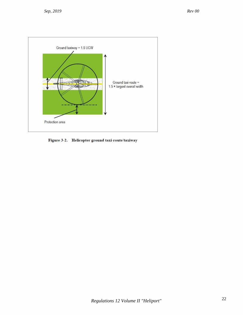
Helicopter ground taxiways and helicopter ground taxi-routes Note 1.— A helicopter ground taxiway is intended to permit the surface movement of a wheeled helicopter under its own power. Note 2.— When a taxiway is intended for use by aeroplanes and helicopters, the provisions for taxiways for aeroplanes and helicopter ground taxiways will be taken into consideration and the more stringent requirements will be applied. 3.1.29 The width of a helicopter ground taxiway shall not be less than 1.5 times the largest width of the undercarriage (UCW) of the helicopters the helicopter ground taxiway is intended to serve. (See Figure 3-2.) 3.1.30 The longitudinal slope of a helicopter ground taxiway shall not exceed 3 per cent.
Sep, 2019 Rev 00
22 Regulations 12 Volume II "Heliport"
Sep, 2019 Rev 00
23 Regulations 12 Volume II "Heliport"
3.1.31 A helicopter ground taxiway shall be static load-bearing and be capable of withstanding the traffic of the helicopters the helicopter ground taxiway is intended to serve. 3.1.32 A helicopter ground taxiway shall be centred on a ground taxi-route. 3.1.33 A helicopter ground taxi-route shall extend symmetrically on each side of the centre line for at least 0.75 times the largest overall width of the helicopters it is intended to serve. Note.— The part of the helicopter ground taxi-route that extends symmetrically on each side of the centre line from 0.5 times the largest overall width of the helicopters it is intended to serve to the outermost limit of the helicopter ground taxi-route is its protection area. 3.1.34 No fixed object shall be permitted above the surface of the ground on a helicopter ground taxi-route, except for frangible objects, which, because of their function, must be located thereon. No mobile object shall be permitted on a ground taxi-route during helicopter movements. 3.1.35 Objects whose function requires them to be located on a helicopter ground taxi-route shall not:
a. be located at a distance of less than 50 cm from the edge of the helicopter ground taxiway; and
b. penetrate a plane originating at a height of 25 cm above the plane of the helicopter
ground taxiway, at a distance of 50 cm from the edge of the helicopter ground taxiway and sloping upwards and outwards at a gradient of 5 per cent.
3.1.36 The helicopter ground taxiway and the helicopter ground taxi-route shall provide rapid drainage but the helicopter ground taxiway transverse slope shall not exceed 2 per cent. 3.1.37 The surface of a helicopter ground taxi-route shall be resistant to the effect of rotor downwash. 3.1.38 For simultaneous operations, the helicopter ground taxi-routes shall not overlap.
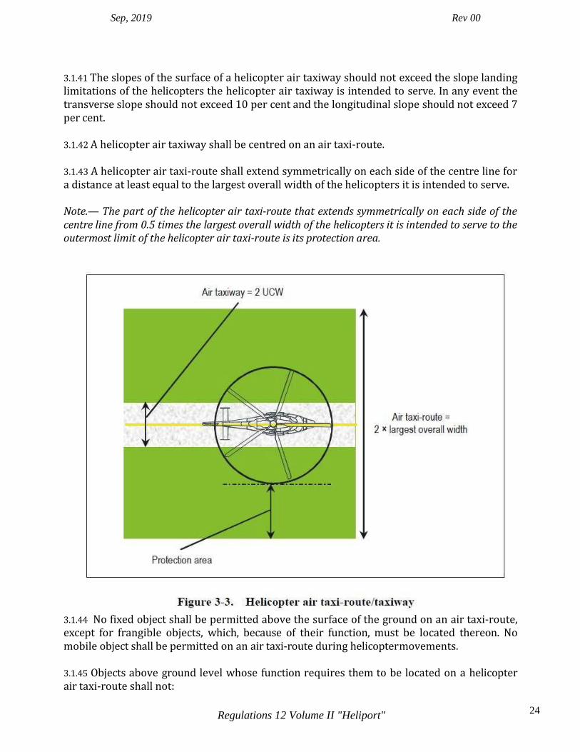
Helicopter air taxiways and helicopter air taxi-routes Note.— A helicopter air taxiway is intended to permit the movement of a helicopter above the surface at a height normally associated with ground effect and at ground speed less than 37km/h (20 kt). 3.1.39 The width of a helicopter air taxiway shall be at least two times the largest width of the undercarriage (UCW) of the helicopters that the helicopter air taxiway is intended to serve. (See Figure 3-3.) 3.1.40 The surface of a helicopter air taxiway should be static load-bearing.
Sep, 2019 Rev 00
24 Regulations 12 Volume II "Heliport"
3.1.41 The slopes of the surface of a helicopter air taxiway should not exceed the slope landing limitations of the helicopters the helicopter air taxiway is intended to serve. In any event the transverse slope should not exceed 10 per cent and the longitudinal slope should not exceed 7 per cent. 3.1.42 A helicopter air taxiway shall be centred on an air taxi-route. 3.1.43 A helicopter air taxi-route shall extend symmetrically on each side of the centre line for a distance at least equal to the largest overall width of the helicopters it is intended to serve. Note.— The part of the helicopter air taxi-route that extends symmetrically on each side of the centre line from 0.5 times the largest overall width of the helicopters it is intended to serve to the outermost limit of the helicopter air taxi-route is its protection area.
3.1.44 No fixed object shall be permitted above the surface of the ground on an air taxi-route, except for frangible objects, which, because of their function, must be located thereon. No mobile object shall be permitted on an air taxi-route during helicopter movements. 3.1.45 Objects above ground level whose function requires them to be located on a helicopter air taxi-route shall not:

Sep, 2019 Rev 00
25 Regulations 12 Volume II "Heliport"
a. be located at a distance of less than 1 m from the edge of the helicopter air taxiway; and
b. penetrate a plane originating at a height of 25 cm above the plane of the helicopter air taxiway, at a distance of 1 m from the edge of the helicopter air taxiway and sloping upwards and outwards at a gradient of 5 per cent.
3.1.46 Objects above ground level whose function requires them to be located on a helicopter air taxi-route should not:
a. be located at a distance of less than 0.5 times the largest overall width of the helicopter for which the helicopter air taxi-route is designed from the centre line of the helicopter air taxiway; and
b. penetrate a plane originating at a height of 25 cm above the plane of the helicopter
air taxiway, at a distance of 0.5 times the largest overall width of the helicopter for which the helicopter air taxi-route is designed from the centre line of the helicopter air taxiway, and sloping upwards and outwards at a gradient of 5 per cent.
3.1.47 The surface of a helicopter air taxi-route shall be resistant to the effect of rotor downwash.
3.1.48 The surface of a helicopter air taxi-route shall provide ground effect.
Sep, 2019 Rev 00
26 Regulations 12 Volume II "Heliport"
3.1.49 For simultaneous operations, the helicopter air taxi-routes shall not overlap.
Helicopter stands Note.— The provisions of this section do not specify the location for helicopter stands but allow a high degree of flexibility in the overall design of the heliport. However, it is not considered good practice to locate helicopter stands under a flight path. See the Heliport Manual (Doc 9261) for further guidance. 3.1.50 When a TLOF is collocated with a helicopter stand, the protection area of the stand shall not overlap the protection area of any other helicopter stand or associated taxi route. 3.1.51 The helicopter stand shall provide rapid drainage but the slope in any direction shall not exceed 2 per cent. Note.— The requirements on the dimensions of helicopter stands assume the helicopter will turn in a hover when operating over a stand. 3.1.52 A helicopter stand intended to be used by helicopters turning in a hover shall be of sufficient size to contain a circle of diameter of at least 1.2 D of the largest helicopter the stand is intended to serve. (See Figure 3-4.) 3.1.53 Where a helicopter stand is intended to be used for taxi-through and where the helicopter using the stand is not required to turn, the minimum width of the stand and associated protection area shall be that of the taxi-route. 3.1.54 Where a helicopter stand is intended to be used for turning, the minimum dimension of the stand and protection area shall be not less than 2 D. 3.1.55 Where a helicopter stand is intended to be used for turning, it shall be surrounded by a protection area which extends for a distance of 0.4 D from the edge of the helicopter stand. 3.1.56 For simultaneous operations, the protection areas of helicopter stands and their associated taxi-routes shall not overlap. (See Figure 3-5.) Note.— Where non-simultaneous operations are envisaged, the protection areas of helicopter stands and their associated taxi-routes may overlap. (See Figure 3-6.) 3.1.57 A helicopter stand and associated protection area intended to be used for air taxiing shall provide ground effect. 3.1.58 No fixed object shall be permitted above the surface of the ground on a helicopter stand. 3.1.59 No fixed object shall be permitted above the surface of the ground in the protection area around a helicopter stand except for frangible objects, which because of their function, must be located there.

Sep, 2019 Rev 00
27 Regulations 12 Volume II "Heliport"
3.1.60 No mobile object shall be permitted on a helicopter stand and the associated protection area during helicopter movements. 3.1.61 Objects whose function requires them to be located in the protection area shall not:
a. if located at a distance of less than 0.75 D from the centre of the helicopter stand, penetrate a plane at a height of 5 cm above the plane of the central zone; and
b. if located at a distance of 0.75 D or more from the centre of the helicopter stand,
penetrate a plane at a height of 25 cm above the plane of the central zone and sloping upwards and outwards at a gradient of 5 per cent.
3.1.62 The central zone of a helicopter stand shall be capable of withstanding the traffic of helicopters it is intended to serve and have a static load-bearing area:
a. of diameter not less than 0.83 D of the largest helicopter it is intended to serve; or
b. for a helicopter stand intended to be used for taxi-through, and where the helicopter using the stand is not required to turn, the same width as the helicopter ground taxiway.
Note.— For a helicopter stand intended to be used for turning on the ground by wheeled helicopters, the dimension of the helicopter stand, including the dimension of the central zone, would need to be significantly increased. See the Heliport Manual (Doc 9261) for further guidance. Location of a final approach and take-off area in relation to a runway or taxiway 3.1.63 Where a FATO is located near a runway or taxiway, and where simultaneous operations are planned, the separation distance between the edge of a runway or taxiway and the edge of a FATO shall not be less than the appropriate dimension in Table 3-1. 3.1.64 A FATO should not be located:
a. near taxiway intersections or holding points where jet engine efflux is likely to cause high turbulence; or
b. near areas where aeroplane vortex wake generation is likely to exist.

Sep, 2019 Rev 00
28 Regulations 12 Volume II "Heliport"

Sep, 2019 Rev 00
29 Regulations 12 Volume II "Heliport"
3.2 Elevated heliports Note 1.— The dimensions of the taxi-routes and helicopter stands include a protection area. Note 2.— Guidance on structural design for elevated heliports is given in the Heliport Manual (Doc 9261). Note 3 –Helicopters operated in performance class 1 are only allowed to operate at elevated heliports. 3.2.1 In the case of elevated heliports, design considerations of the different elements of the heliport shall take into account additional loading resulting from the presence of personnel, snow, freight, refuelling, fire fighting equipment, etc.
Final approach and take-off areas and touchdown and lift-off areas Note.— On elevated heliports it is presumed that the FATO and one TLOF will be coincidental. 3.2.2 An elevated heliport shall be provided with one FATO.
3.2.3 A FATO shall be obstacle free.
3.2.4 The dimensions of the FATO shall be:
a. where intended to be used by helicopters operated in performance class 1, as prescribed in the helicopter flight manual (HFM) except that, in the absence of width specifications, the width shall be not less than 1 D of the largest helicopter the FATO is intended to serve;
b. Skipped the number.
Sep, 2019 Rev 00
30 Regulations 12 Volume II "Heliport"
Note.— Local conditions, such as elevation and temperature, may need to be considered when determining the size of a FATO. Guidance is given in the Heliport Manual (Doc 9261).
3.2.5 Skipped the number. 3.2.6 Slopes on a FATO at an elevated heliport shall be sufficient to prevent accumulation of water on the surface of the area, but shall not exceed 2 per cent in any direction. 3.2.7 The FATO shall be dynamic load-bearing.
3.2.8 The surface of the FATO shall be:
a. resistant to the effects of rotor downwash; and
b. free of irregularities that would adversely affect the take-off or landing of helicopters. 3.2.9 The FATO should provide ground effect. Helicopter clearways 3.2.10 When a helicopter clearway is provided, it shall be located beyond the end of the rejected take-off area available. 3.2.11 The width of a helicopter clearway should not be less than that of the associated safety area. 3.2.12 When solid, the surface of the helicopter clearway should not project above a plane having an upward slope of 3 per cent, the lower limit of this plane being a horizontal line which is located on the periphery of the FATO. 3.2.13 An object situated on a helicopter clearway which may endanger helicopters in the air should be regarded as an obstacle and should be removed.
Touchdown and lift-off areas 3.2.14 One TLOF shall be coincidental with the FATO. Note.— Additional TLOFs may be collocated with helicopter stands. 3.2.15 For a TLOF coincidental with the FATO, the dimensions and the characteristics of the TLOF shall be the same as those of the FATO. 3.2.16 When the TLOF is collocated with a helicopter stand, the TLOF shall be of sufficient size to contain a circle of diameter of at least 0.83 D of the largest helicopter the area is intended to serve.
Sep, 2019 Rev 00
31 Regulations 12 Volume II "Heliport"
3.2.17 Slopes on a TLOF collocated with a helicopter stand shall be sufficient to prevent accumulation of water on the surface of the area, but shall not exceed 2 per cent in any direction. 3.2.18 When the TLOF is collocated with a helicopter stand and intended to be used by ground taxiing helicopters only, the TLOF shall at least be static load-bearing and be capable of withstanding the traffic of the helicopters the area is intended to serve. 3.2.19 When the TLOF is collocated with a helicopter stand and intended to be used by air taxiing helicopters, the TLOF shall have a dynamic load-bearing area. Safety areas 3.2.20 The FATO shall be surrounded by a safety area which need not be solid. 3.2.21 A safety area surrounding a FATO intended to be used by helicopters operated in performance class 1 in visual meteorological conditions (VMC) shall extend outwards from the periphery of the FATO for a distance of at least 3 m or 0.25 D, whichever is greater, of the largest helicopter the FATO is intended to serve and:
a. each external side of the safety area shall be at least 2 D where the FATO is quadrilateral; or
b. the outer diameter of the safety area shall be at least 2 D where the FATO is circular.
3.2.22 Skipped the number. 3.2.23 There shall be a protected side slope rising at 45 degrees from the edge of the safety area to a distance of 10 m, whose surface shall not be penetrated by obstacles, except that when obstacles are located to one side of the FATO only, they may be permitted to penetrate the side slope surface. 3.2.24 No fixed object shall be permitted on a safety area, except for frangible objects, which, because of their function, must be located on the area. No mobile object shall be permitted on a safety area during helicopter operations. 3.2.25 Objects whose function require them to be located on the safety area shall not exceed a height of 25 cm when located along the edge of the FATO nor penetrate a plane originating at a height of 25 cm above the edge of the FATO and sloping upwards and outwards from the edge of the FATO at a gradient of 5 per cent. 3.2.26 In the case of a FATO of diameter less than 1 D, the maximum height of the objects whose functions require them to be located on the safety area should not exceed a height of 5 cm. 3.2.27 The surface of the safety area, when solid, shall not exceed an upward slope of 4 per cent outwards from the edge of the FATO.

Sep, 2019 Rev 00
32 Regulations 12 Volume II "Heliport"
3.2.28 Where applicable, the surface of the safety area shall be prepared in a manner to prevent flying debris caused by rotor downwash. 3.2.29 The surface of the safety area abutting the FATO shall be continuous with the FATO. Helicopter ground taxiways and ground taxi-routes Note.— The following specifications are intended for the safety of simultaneous operations during the manoeuvring of helicopters. However, the wind velocity induced by the rotor downwash might have to be considered. 3.2.30 The width of a helicopter ground taxiway shall not be less than 2 times the largest width of the undercarriage (UCW) of the helicopters the ground taxiway is intended to serve. 3.2.31 The longitudinal slope of a helicopter ground taxiway shall not exceed 3 per cent. 3.2.32 A helicopter ground taxiway shall be static load-bearing and be capable of withstanding the traffic of the helicopters the helicopter ground taxiway is intended to serve. 3.2.33 A helicopter ground taxiway shall be centred on a ground taxi-route. 3.2.34 A helicopter ground taxi-route shall extend symmetrically on each side of the centre line to a distance not less than the largest overall width of the helicopters it is intended to serve. 3.2.35 No objects shall be permitted on a helicopter ground taxi-route, except for frangible objects, which, because of their function, must be located there. 3.2.36 The helicopter ground taxiway and the ground taxi-route shall provide rapid drainage but the helicopter ground taxiway transverse slope shall not exceed 2 per cent. 3.2.37 The surface of a helicopter ground taxi-route shall be resistant to the effect of rotor downwash. Helicopter air taxiways and air taxi-routes Note.— A helicopter air taxiway is intended to permit the movement of a helicopter above the surface at a height normally associated with ground effect and at ground speed less than 37 km/h (20 kt). 3.2.38 The width of a helicopter air taxiway shall be at least three times the largest width of the undercarriage (UCW) of the helicopters the air taxiway is intended to serve. 3.2.39 The surface of a helicopter air taxiway shall be dynamic load-bearing. 3.2.40 The transverse slope of the surface of a helicopter air taxiway shall not exceed 2 per cent and the longitudinal slope shall not exceed 7 per cent. In any event, the slopes shall not exceed the slope landing limitations of the helicopters the air taxiway is intended to serve.
Sep, 2019 Rev 00
33 Regulations 12 Volume II "Heliport"
3.2.41 A helicopter air taxiway shall be centred on an air taxi-route. 3.2.42 A helicopter air taxi-route shall extend symmetrically on each side of the centre line to a distance not less than the largest overall width of the helicopters it is intended to serve. 3.2.43 No objects shall be permitted on an air taxi-route, except for frangible objects, which, because of their function, must be located thereon. 3.2.44 The surface of an air taxi-route shall be resistant to the effect of rotor downwash.
3.2.45 The surface of an air taxi-route shall provide ground effect.
Aprons 3.2.46 The slope in any direction on a helicopter stand shall not exceed 2 per cent. 3.2.47 A helicopter stand shall be of sufficient size to contain a circle of diameter of at least
1.2 D of the largest helicopters the stand is intended to serve. 3.2.48 If a helicopter stand is used for taxi-through, the minimum width of the stand and associated protection area shall be that of the taxi-route. 3.2.49 When a helicopter stand is used for turning, the minimum dimension of the stand and protection area shall be not less than 2 D. 3.2.50 When a helicopter stand is used for turning, it shall be surrounded by a protection area which extends for a distance of 0.4 D from the edge of the helicopter stand. 3.2.51 For simultaneous operations, the protection area of helicopter stands and their associated taxi-routes shall not overlap. Note.— Where non-simultaneous operations are envisaged, the protection area of helicopter stands and their associated taxi-routes may overlap. 3.2.52 When intended to be used for ground taxi operations by wheeled helicopters, the dimensions of a helicopter stand shall take into account the minimum turn radius of the wheeled helicopters the stand is intended to serve. 3.2.53 A helicopter stand and associated protection area intended to be used for air taxiing shall provide ground effect. 3.2.54 No fixed objects shall be permitted on a helicopter stand and the associated protection area. 3.2.55 The central zone of the helicopter stand shall be capable of withstanding the traffic of the helicopters it is intended to serve and have a load-bearing area:
a. of diameter not less than 0.83 D of the largest helicopter it is intended to serve; or
Sep, 2019 Rev 00
34 Regulations 12 Volume II "Heliport"
b. for a helicopter stand intended to be used for ground taxi-through, the same width as the ground taxiway.
3.2.56 The central zone of a helicopter stand intended to be used for ground taxiing only shall be static load-bearing. 3.2.57 The central zone of a helicopter stand intended to be used for air taxiing shall be dynamic load-bearing. Note.— For a helicopter stand intended to be used for turning on the ground, the dimension of the central zone might have to be increased.
3.3 Helidecks Note.— The following specifications are for helidecks located on structures engaged in such activities as mineral exploitation, research or construction. See 3.4 for shipboard heliport provisions.
Final approach and take-off areas and touchdown and lift-off areas Note 1.— For helidecks that have a 1 D or larger FATO it is presumed that the FATO and the TLOF will always occupy the same space and have the same load bearing characteristics so as to be coincidental. For helidecks that are less than 1 D, the reduction in size is only applied to the TLOF which is a load bearing area. In this case, the FATO remains at 1 D but the portion extending beyond the TLOF perimeter need not be load bearing for helicopters. The TLOF and the FATO may be assumed to be collocated. Note 2.— Guidance on the effects of airflow direction and turbulence, prevailing wind velocity and high temperatures from gas turbine exhausts or flare-radiated heat on the location of the FATO is given in the Heliport Manual (Doc 9261). Note 3.— Guidance on the design and markings for helideck parking areas is given in the Heliport Manual (Doc 9261). 3.3.1 The specifications in paragraphs 3.3.14 and 3.3.15 shall be applicable for helidecks completed on or after 1 January 2012. 3.3.2 A helideck shall be provided with one FATO and one coincident or collocated TLOF. 3.3.3 A FATO may be any shape but shall be of sufficient size to contain an area within which can be accommodated a circle of diameter of not less than 1 D of the largest helicopter the helideck is intended to serve. 3.3.4 A TLOF may be any shape but shall be of sufficient size to contain:
Sep, 2019 Rev 00
35 Regulations 12 Volume II "Heliport"
a. for helicopters with an MTOM of more than 3 175 kg, an area within which can be accommodated a circle of diameter not less than 1 D of the largest helicopter the helideck is intended to serve; and
b. for helicopters with an MTOM of 3 175 kg or less, an area within which can be
accommodated a circle of diameter not less than 0.83 D of the largest helicopter the helideck is intended to serve.
3.3.5 For helicopters with a MTOM of 3175 kg or less, the TLOF should be of sufficient size to contain an area within which can be accommodated a circle of diameter of not less than 1 D of the largest helicopter the helideck is intended to serve. 3.3.6 A helideck shall be arranged to ensure that a sufficient and unobstructed air-gap is provided which encompasses the full dimensions of the FATO. Note.— Specific guidance on the characteristics of an air-gap is given in the Heliport Manual (Doc 9261). As a general rule, except for shallow superstructures of three stories or less, a sufficient air- gap will be at least 3 m. 3.3.7 The FATO should be located so as to avoid, as far as is practicable, the influence of environmental effects, including turbulence, over the FATO, which could have an adverse impact on helicopter operations. 3.3.8 The TLOF shall be dynamic load-bearing.
3.3.9 The TLOF shall provide ground effect.
3.3.10 No fixed object shall be permitted around the edge of the TLOF except for frangible objects, which, because of their function, must be located thereon. 3.3.11 For any TLOF 1D or greater and any TLOF designed for use by helicopters having a D-value of greater than 16.0 m, objects installed in the obstacle- free sector whose function requires them to be located on the edge of the TLOF shall not exceed a height of 25 cm. 3.3.12 For any TLOF 1 D or greater and any TLOF designed for use by helicopters having a D-value of greater than 16.0 m, objects installed in the obstacle-free sector whose function requires them to be located on the edge of the TLOF should be as low as possible and in any case not exceed a height of 15 cm. 3.3.13 For any TLOF designed for use by helicopters having a D-value of 16.0 m or less, and any TLOF having dimensions of less than 1D, objects installed in the obstacle-free sector whose function requires them to be located on the edge of the TLOF, shall not exceed a height of 5 cm. Note.— Lighting that is mounted at a height of less than 25 cm is typically assessed for adequacy of visual cues before and after installation.
Sep, 2019 Rev 00
36 Regulations 12 Volume II "Heliport"
3.3.14 Objects whose function requires them to be located within the TLOF (such as lighting or nets) shall not exceed a height of 2.5 cm. Such objects shall only be present if they do not represent a hazard to helicopters. Note.— Examples of potential hazards include nets or raised fittings on the deck that might induce dynamic rollover for helicopters equipped with skids. 3.3.15 Safety devices such as safety nets or safety shelves shall be located around the edge of a helideck but shall not exceed the height of the TLOF. 3.3.16 The surface of the TLOF shall be skid-resistant to both helicopters and persons and be sloped to prevent pooling of water. Note.— Guidance on rendering the surface of the TLOF skid-resistant is contained in the Heliport Manual (Doc 9261).
3.4 Shipboard heliports 3.4.1 The specifications in paragraph 3.4.16 and 3.4.17 shall be applicable to shipboard heliports completed on or after 1 January 2012 AND 1 January 2015, respectively. 3.4.2 When helicopter operating areas are provided in the bow or stern of a ship or are purpose-built above the ship’s structure, they shall be regarded as purpose-built shipboard heliports.
Final approach and take-off areas and touchdown and lift-off areas Note.— Except for the arrangement described in 3.4.8 b), for shipboard heliports it is presumed that the FATO and the TLOF will be coincidental. Guidance on the effects of airflow direction and turbulence, prevailing wind velocity and high temperature from gas turbine exhausts or flare- radiated heat on the location of the FATO is given in the Heliport Manual (Doc 9261). 3.4.3 A shipboard heliport shall be provided with one FATO and one coincidental or collocated TLOF. 3.4.4 A FATO may be any shape but shall be of sufficient size to contain an area within which can be accommodated a circle of diameter of not less than 1 D of the largest helicopter the heliport is intended to serve. 3.4.5 The TLOF of a shipboard heliport shall be dynamic load-bearing.
3.4.6 The TLOF of a shipboard heliport shall provide ground effect.
Sep, 2019 Rev 00
37 Regulations 12 Volume II "Heliport"
3.4.7 For purpose-built shipboard heliports provided in a location other than the bow or stern, the TLOF shall be of sufficient size to contain a circle with a diameter not less than 1 D of the largest helicopter the heliport is intended to serve. 3.4.8 For purpose-built shipboard heliports provided in the bow or stern of a ship, the TLOF shall be of sufficient size to:
a. contain a circle with a diameter not less than 1 D of the largest helicopter the heliport is intended to serve; or
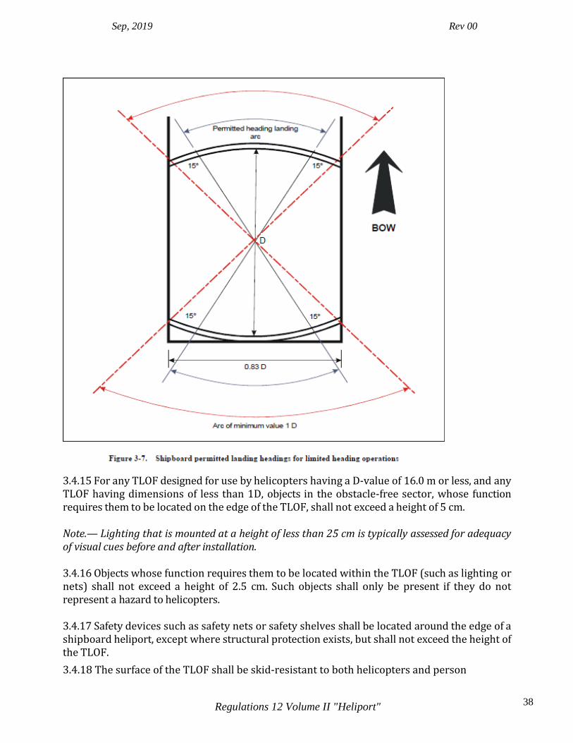
b. for operations with limited touchdown directions, contain an area within which can
be accommodated two opposing arcs of a circle with a diameter of not less than 1 D in the helicopter’s longitudinal direction. The minimum width of the heliport shall be not less than0.83 D. (See Figure 3-7.)
Note 1.— The ship will need to be manoeuvred to ensure that the relative wind is appropriate to the direction of the helicopter touchdown heading. Note 2.— The touchdown heading of the helicopter is limited to the angular distance subtended by the 1 D arc headings, minus the angular distance which corresponds to 15 degrees at each end of the arc. 3.4.9 For non-purpose-built shipboard heliports, the TLOF shall be of sufficient size to contain a circle with a diameter not less than 1 D of the largest helicopter the heliport is intended to serve. 3.4.10 A shipboard heliport shall be arranged to ensure that a sufficient and unobstructed air- gap is provided which encompasses the full dimensions of the FATO. Note.— Specific guidance on the characteristics of an air-gap is given in the Heliport Manual (Doc 9261). As a general rule, except for shallow superstructures of three stories or less, a sufficient air- gap will be at least 3 m. 3.4.11 The FATO should be located so as to avoid, as far as is practicable, the influence of environmental effects, including turbulence, over the FATO, which could have an adverse impact on helicopter operations. 3.4.12 No fixed object shall be permitted around the edge of the TLOF except for frangible objects, which, because of their function, must be located thereon. 3.4.13 For any TLOF 1 D or greater and any TLOF designed for use by helicopters having a D-value of greater than 16.0 m, objects installed in the obstacle- free sector whose function requires them to be located on the edge of the TLOF shall not exceed a height of 25 cm. 3.4.14 For any TLOF 1D or greater and any TLOF designed for use by helicopters having a D-value of greater than 16.0 m, objects installed in the obstacle-free sector whose function requires them to be located on the edge of the TLOF should be as low as possible and in any case not exceed a height of 15 cm.
Sep, 2019 Rev 00
38 Regulations 12 Volume II "Heliport"
3.4.15 For any TLOF designed for use by helicopters having a D-value of 16.0 m or less, and any TLOF having dimensions of less than 1D, objects in the obstacle-free sector, whose function requires them to be located on the edge of the TLOF, shall not exceed a height of 5 cm. Note.— Lighting that is mounted at a height of less than 25 cm is typically assessed for adequacy of visual cues before and after installation. 3.4.16 Objects whose function requires them to be located within the TLOF (such as lighting or nets) shall not exceed a height of 2.5 cm. Such objects shall only be present if they do not represent a hazard to helicopters. 3.4.17 Safety devices such as safety nets or safety shelves shall be located around the edge of a shipboard heliport, except where structural protection exists, but shall not exceed the height of the TLOF.
3.4.18 The surface of the TLOF shall be skid-resistant to both helicopters and person

Sep, 2019 Rev 00
39 Regulations 12 Volume II "Heliport"
CHAPTER 4. OBSTACLE ENVIRONMENT Note.— The objectives of the specifications in this chapter are to describe the airspace around heliports so as to permit intended helicopter operations to be conducted safely and to prevent, where appropriate State controls exist, heliports from becoming unusable by the growth of obstacles around them. This is achieved by establishing a series of obstacle limitation surfaces that define the limits to which objects may project into the airspace. 4.1 Obstacle limitation surfaces and sectors
Approach surface
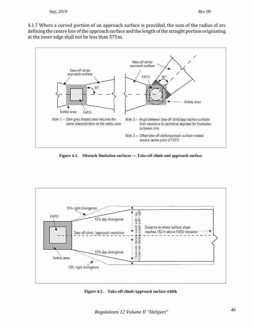
4.1.1 Description: An inclined plane or a combination of planes or, when a turn is involved, a complex surface sloping upwards from the end of the safety area and centred on a line passing through the centre of the FATO. Note.— See Figures 4-1, 4-2, 4-3 and 4-4 for depiction of surfaces. See Table 4-1 for dimensions and slopes of surfaces. 4.1.2 Characteristics: The limits of an approach surface shall comprise:
a. an inner edge horizontal and equal in length to the minimum specified width/diameter of the FATO plus the safety area, perpendicular to the centre line of the approach surface and located at the outer edge of the safety area;
b. two side edges originating at the ends of the inner edge diverging uniformly at a
specified rate from the vertical plane containing the centre line of the FATO; and:
c. an outer edge horizontal and perpendicular to the centre line of the approach surface and at a specified height of 152 m (500 ft) above the elevation of the FATO.
4.1.3 The elevation of the inner edge shall be the elevation of the FATO at the point on the inner edge that is intersected by the centre line of the approach surface. For heliports intended to be used by helicopters operated in performance class 1 and when approved by the Director General of Civil Aviation, the origin of the inclined plane may be raised directly above the FATO. 4.1.4 The slope(s) of the approach surface shall be measured in the vertical plane containing the centre line of the surface. 4.1.5 In the case of an approach surface involving a turn, the surface shall be a complex surface containing the horizontal normals to its centre line and the slope of the centre line shall be the same as that for a straight approach surface. Note.— See Figure 4-5. 4.1.6 In the case of an approach surface involving a turn, the surface shall not contain more than one curved portion.
Sep, 2019 Rev 00
40 Regulations 12 Volume II "Heliport"
4.1.7 Where a curved portion of an approach surface is provided, the sum of the radius of arc defining the centre line of the approach surface and the length of the straight portion originating at the inner edge shall not be less than 575 m.

Sep, 2019 Rev 00
41 Regulations 12 Volume II "Heliport"
Note 1.— This example diagram does not represent any specific profile, technique or helicopter type and is intended to show a generic example. An approach profile and a back-up procedure for departure profile are depicted. Specific manufacturers operations in performance class 1 may be represented differently in the specific Helicopter Flight Manual. Annex 6, Part 3, Attachment A provides back-up procedures that may be useful for operations in performance class 1. Note 2.— The approach/landing profile may not be the reverse of the take-off profile.
Sep, 2019 Rev 00
42 Regulations 12 Volume II "Heliport"
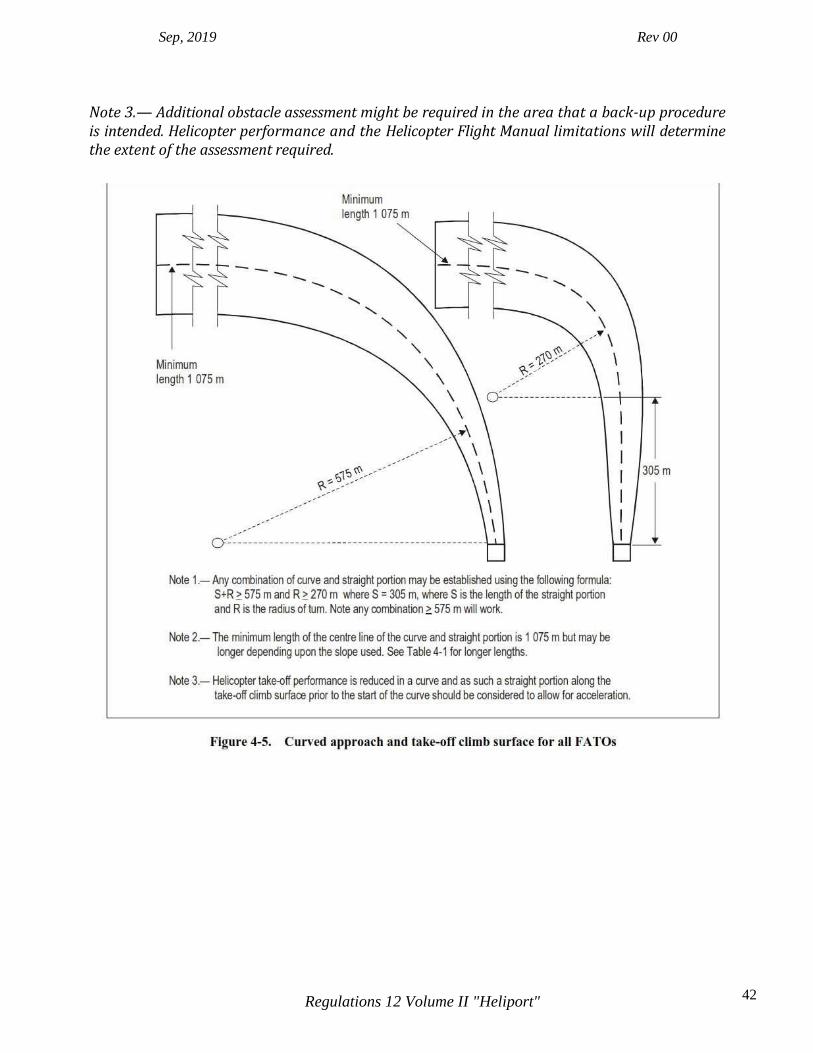
Note 3.— Additional obstacle assessment might be required in the area that a back-up procedure is intended. Helicopter performance and the Helicopter Flight Manual limitations will determine the extent of the assessment required.

Sep, 2019 Rev 00
43 Regulations 12 Volume II "Heliport"
i. The approach and take-off climb surface lengths of 3 386 m, 1 075 m and 1 220 m associated with the respective slopes, brings the helicopter to 152 m (500 ft) above FATO elevation.
ii. Seven rotor diameters overall width for day operations or 10 rotor diameters overall width
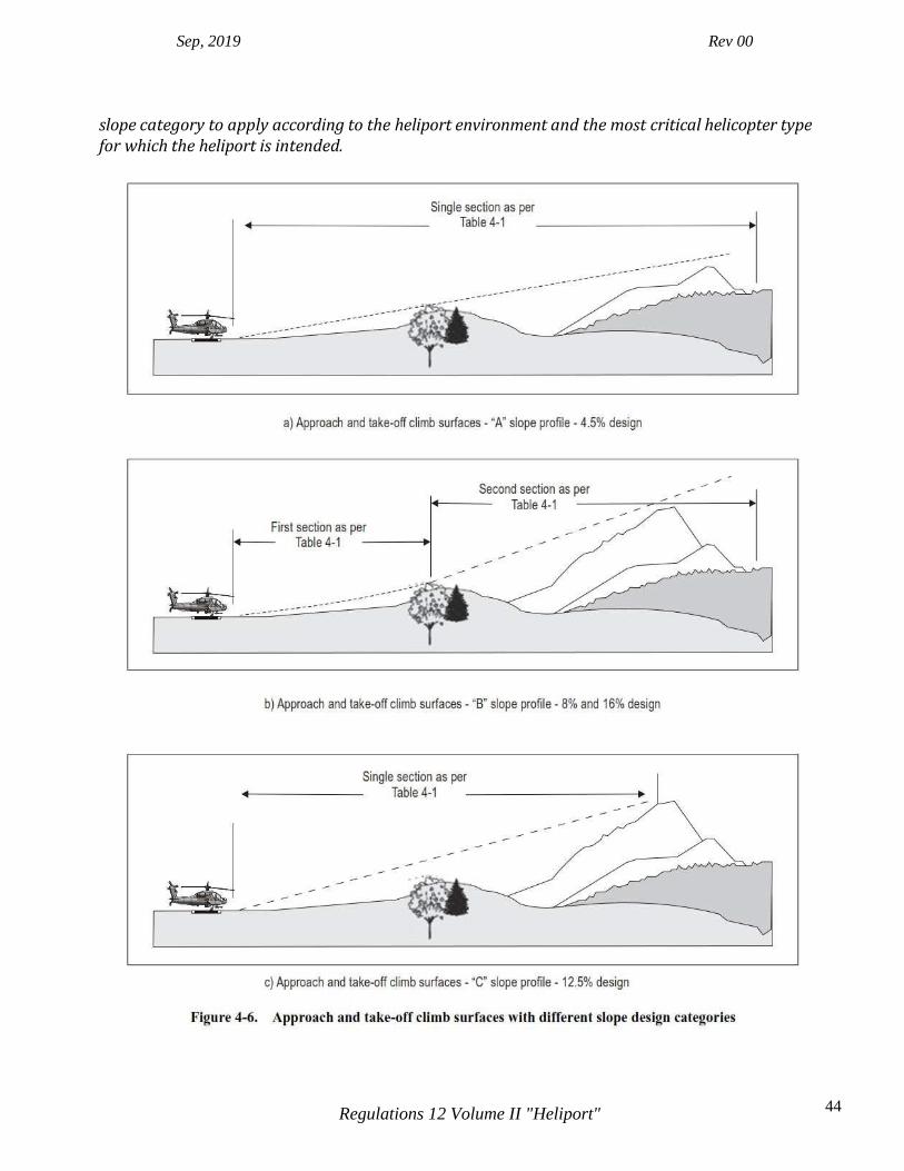
for night operations. Note.— The slope design categories in Table 4-1 may not be restricted to a specific performance class of operation and may be applicable to more than one performance class of operation. The slope design categories depicted in Table 4-1 represent minimum design slope angles and not operational slopes. Slope category “A” generally corresponds with helicopters operated in performance class 1; slope category “B” generally corresponds with helicopters operated in performance class 3; and slope category “C” generally corresponds with helicopters operated in performance class 2. Consultation with helicopter operators will help to determine the appropriate
Sep, 2019 Rev 00
44 Regulations 12 Volume II "Heliport"
slope category to apply according to the heliport environment and the most critical helicopter type for which the heliport is intended.

Sep, 2019 Rev 00
45 Regulations 12 Volume II "Heliport"
4.1.8 Any variation in the direction of the centre line of an approach surface shall be designed so as not to necessitate a turn radius less than 270 m. Note.— For heliports intended to be used by helicopters operated in performance class 2 and 3, it is good practice for the approach paths to be selected so as to permit safe forced landing or one- engine-inoperative landings such that, as a minimum requirement, injury to persons on the ground or water or damage to property are minimized. The most critical helicopter type for which the heliport is intended and the ambient conditions may be factors in determining the suitability of such areas.
Transitional surface Note.— For a FATO at a heliport without a PinS approach incorporating a visual segment surface (VSS) there is no requirement to provide transitional surfaces. 4.1.9 Description. A complex surface along the side of the safety area and part of the side of the approach/take-off climb surface, that slopes upwards and outwards to a predetermined height of 45 m (150 ft). Note.— See Figure 4-3. See Table 4-1 for dimensions and slopes of surfaces. 4.1.10 Characteristics. The limits of a transitional surface shall comprise:
a. a lower edge beginning at a point on the side of the approach/take-off climb surface at a specified height above the lower edge extending down the side of the approach/take-off climb surface to the inner edge of the approach/take- off climb surface and from there along the length of the side of the safety area parallel to the centre line of the FATO; and
b. an upper edge located at a specified height above the lower edge as set out in Table 4-1.
4.1.11 The elevation of a point on the lower edge shall be:
a. along the side of the approach/take-off climb surface — equal to the elevation of the approach/take-off climb surface at that point; and
b. along the safety area — equal to the elevation of the inner edge of the
approach/take-off climb surface. Note 1.— If the origin of the inclined plane of the approach/take-off climb surface is raised as approved by an appropriate authority, the elevation of the origin of the transitional surface will be raised accordingly. Note 2.— As a result of b) the transitional surface along the safety area will be curved if the profile of the FATO is curved, or a plane if the profile is a straight line. 4.1.12 The slope of the transitional surface shall be measured in a vertical plane at right angles to the centre line of the FATO.
Sep, 2019 Rev 00
46 Regulations 12 Volume II "Heliport"
Take-off climb surface 4.1.13 Description. An inclined plane, a combination of planes or, when a turn is involved, a complex surface sloping upwards from the end of the safety area and centred on a line passing through the centre of the FATO. Note.— See Figures 4-1, 4-2, 4-3 and 4-4 for depiction of surfaces. See Table 4-1 for dimensions and slopes of surfaces. 4.1.14 Characteristics. The limits of a take-off climb surface shall comprise:
a. an inner edge horizontal and equal in length to the minimum specified width/diameter of the FATO plus the safety area, perpendicular to the centre line of the take-off climb surface and located at the outer edge of the safety area;
b. two side edges originating at the ends of the inner edge and diverging uniformly at a
specified rate from the vertical plane containing the centre line of the FATO; and
c. an outer edge horizontal and perpendicular to the centre line of the take-off climb surface and at a specified height of 152 m (500 ft) above the elevation of the FATO.
4.1.15 The elevation of the inner edge shall be the elevation of the FATO at the point on the inner edge that is intersected by the centre line of the take-off climb surface. For heliports intended to be used by helicopters operated in performance class 1 and when approved by an appropriate authority, the origin of the inclined plane may be raised directly above the FATO. 4.1.16 Where a clearway is provided the elevation of the inner edge of the take-off climb surface shall be located at the outer edge of the clearway at the highest point on the ground based on the centre line of the clearway. 4.1.17 In the case of a straight take-off climb surface, the slope shall be measured in the vertical plane containing the centre line of the surface. 4.1.18 In the case of a take-off climb surface involving a turn, the surface shall be a complex surface containing the horizontal normals to its centre line and the slope of the centre line shall be the same as that for a straight take-off climb surface. Note.— See Figure 4-5. 4.1.19 In the case of a take-off climb surface involving a turn, the surface shall not contain more than one curved portion. 4.1.20 Where a curved portion of a take-off climb surface is provided the sum of the radius of arc defining the centre line of the take-off climb surface and the length of the straight portion originating at the inner edge shall not be less than 575 m.
Sep, 2019 Rev 00
47 Regulations 12 Volume II "Heliport"
4.1.21 Any variation in the direction of the centre line of a take-off climb surface shall be designed so as not to necessitate a turn of radius less than 270 m. Note 1.— Helicopter take-off performance is reduced in a curve and as such a straight portion along the take-off climb surface prior to the start of the curve allows for acceleration. Note 2.— For heliports intended to be used by helicopters operated in performance class 2 and 3 it is good practice for the departure paths to be selected so as to permit safe forced landings or one- engine-inoperative landings such that, as a minimum requirement, injury to persons on the ground or water or damage to property are minimized. The most critical helicopter type for which the heliport is intended and the ambient conditions may be factors in determining the suitability of such areas. Obstacle-free sector/surface — helidecks 4.1.22 Description. A complex surface originating at and extending from, a reference point on the edge of the FATO of a helideck. In the case of a TLOF of less than 1 D, the reference point shall be located not less than 0.5 D from the centre of the TLOF. 4.1.23 Characteristics. An obstacle-free sector/surface shall subtend an arc of specified angle. 4.1.24 A helideck obstacle-free sector shall comprise of two components, one above and one below helideck level: Note.— See Figure 4-7.
a. Above helideck level. The surface shall be a horizontal plane level with the elevation of the helideck surface that subtends an arc of at least 210 degrees with the apex located on the periphery of the D circle extending outwards to a distance that will allow for an unobstructed departure path appropriate to the helicopter the helideck is intended to serve.
b. Below helideck level. Within the (minimum) 210-degree arc, the surface shall
additionally extend downward from the edge of the FATO below the elevation of the helideck to water level for an arc of not less than 180 degrees that passes through the centre of the FATO and outwards to a distance that will allow for safe clearance from the obstacles below the helideck in the event of an engine failure for the type of helicopter the helideck is intended to serve.
Note.— For both the above obstacle-free sectors for helicopters operated in performance class 1 or 2, the horizontal extent of these distances from the helideck will be compatible with the one- engine-inoperative capability of the helicopter type to be used.
Limited obstacle sector/surface — helidecks Note.— Where obstacles are necessarily located on the structure, a helideck may have a limited obstacle sector (LOS).

Sep, 2019 Rev 00
48 Regulations 12 Volume II "Heliport"
4.1.25 Description. A complex surface originating at the reference point for the obstacle-free sector and extending over the arc not covered by the obstacle-free sector within which the height of obstacles above the level of the TLOF will be prescribed. 4.1.26 Characteristics. A limited obstacle sector shall not subtend an arc greater than 150 degrees. Its dimensions and location shall be as indicated in Figure 4-8 for a 1 D FATO with coincidental TLOF and Figure 4-9 for a 0.83 D TLOF. 4.2 Obstacle limitation requirements Note 1.— The requirements for obstacle limitation surfaces are specified on the basis of the intended use of a FATO, i.e. approach manoeuvre to hover or landing, or take-off manoeuvre and type of approach, and are intended to be applied when such use is made of the FATO. In cases where operations are conducted to or from both directions of a FATO, then the function of certain surfaces may be nullified because of more stringent requirements of another lower surface. Note 2.— If a visual approach slope indicator (VASI) is installed, there are additional obstacle protection surfaces, detailed in Chapter 5, that need to be considered and may be more demanding than the obstacle limitation surfaces prescribed in Table 4-1.
Surface-level heliports 4.2.1 The following obstacle limitation surfaces shall be established for a FATO at heliports with a PinS approach procedure utilizing a visual segment surface:
a. take-off climb surface;
b. approach surface; and
c. transitional surfaces. Note 1.— See Figure 4-3. Note 2.— The Procedures for Air Navigation Services — Aircraft Operations, (PANS-OPS, Doc 8168), Volume II, Part IV — Helicopters, details procedure design criteria. 4.2.2 The following obstacle limitation surfaces shall be established for a FATO at heliports, other than specified in 4.2.1, including heliports with a PinS approach procedure where a visual segment surface is not provided:
a. take-off climb surface;
b. approach surface.

Sep, 2019 Rev 00
49 Regulations 12 Volume II "Heliport"
4.2.3 The slopes of the obstacle limitation surfaces shall not be greater than, and their other dimensions not less than, those specified in Table 4-1 and shall be located as shown in Figures 4-1, 4-2 and 4-6. 4.2.4 For heliports that have an approach/take-off climb surface with a 4.5 per cent slope design, objects shall be permitted to penetrate the obstacle limitation surface, if the results of an aeronautical study approved by an appropriate authority have reviewed the associated risks and mitigation measures. Note 1.— The identified objects may limit the heliport operation. Note 2.— Annex 6, Part 3, provides procedures that may be useful in determining the extent of obstacle penetration. 4.2.5 New objects or extensions of existing objects shall not be permitted above any of the surfaces in 4.2.1 and 4.2.2 except when shielded by an existing immovable object or after an aeronautical study approved by an appropriate authority determines that the object will not adversely affect the safety or significantly affect the regularity of operations of helicopters. Note.— Circumstances in which the shielding principle may reasonably be applied are described in the Airport Services Manual (Doc 9137), Part 6. 4.2.6 Existing objects above any of the surfaces in 4.2.1 and 4.2.2 should, as far as practicable, be removed except when the object is shielded by an existing immovable object or after an aeronautical study approved by an appropriate authority determines that the object will not adversely affect the safety or significantly affect the regularity of operations of helicopters. Note.— The application of curved approach or take-off climb surfaces as specified in 4.1.5 or 4.1.18 may alleviate the problems created by objects infringing these surfaces. 4.2.7 A surface-level heliport shall have at least one approach and take-off climb surface. An aeronautical study shall be undertaken by an appropriate authority when only a single approach and take-off climb surface is provided considering as a minimum, the following factors:
a. the area/terrain over which the flight is being conducted; b. the obstacle environment surrounding the heliport; c. the performance and operating limitations of helicopters intending to use the heliport;
and d. the local meteorological conditions including the prevailing winds.
4.2.8 A surface-level heliport should have at least two approach and take-off climb surfaces to avoid downwind conditions, minimize crosswind conditions and permit for a balked landing. Note.— See the Heliport Manual (Doc 9261) for guidance.
Sep, 2019 Rev 00
50 Regulations 12 Volume II "Heliport"
Elevated heliports 4.2.9 The obstacle limitation surfaces for elevated heliports shall conform to the requirements for surface-level heliports specified in 4.2.1 to 4.2.6. 4.2.10 An elevated heliport shall have at least one approach and take-off climb surface. An aeronautical study shall be undertaken by an appropriate authority when only a single approach and take-off climb surface is provided considering as a minimum, the following factors:
a. the area/terrain over which the flight is being conducted;
b. the obstacle environment surrounding the heliport;

Sep, 2019 Rev 00
51 Regulations 12 Volume II "Heliport"

Sep, 2019 Rev 00
52 Regulations 12 Volume II "Heliport"
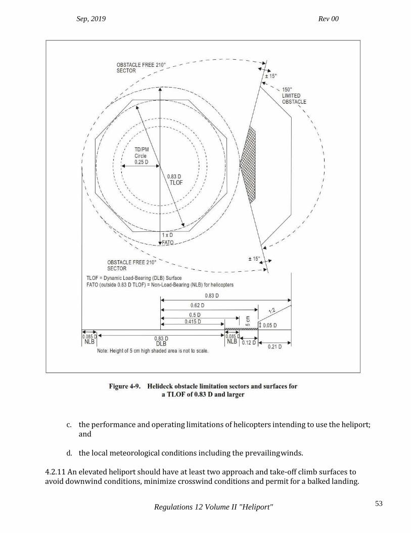
Sep, 2019 Rev 00
53 Regulations 12 Volume II "Heliport"
c. the performance and operating limitations of helicopters intending to use the heliport; and
d. the local meteorological conditions including the prevailing winds.
4.2.11 An elevated heliport should have at least two approach and take-off climb surfaces to avoid downwind conditions, minimize crosswind conditions and permit for a balked landing.

Sep, 2019 Rev 00
54 Regulations 12 Volume II "Heliport"
Note.— See the Heliport Manual (Doc 9261) for guidance. Helidecks 4.2.12 A helideck shall have an obstacle-free sector. Note.— A helideck may have a LOS (see 4.1.26). 4.2.13 There shall be no fixed obstacles within the obstacle-free sector above the obstacle- free surface. 4.2.14 In the immediate vicinity of the helideck, obstacle protection for helicopters shall be provided below the helideck level. This protection shall extend over an arc of at least 180 degrees with the origin at the centre of the FATO, with a descending gradient having a ratio of one unit horizontally to five units vertically from the edges of the FATO within the 180-degree sector. This descending gradient may be reduced to a ratio of one unit horizontally to three units vertically within the 180-degree sector for multi-engine helicopters operated in performance class 1 or 2. (See Figure 4-7.) Note.— Where there is a requirement to position, at sea surface level, one or more offshore support vessel(s) (e.g. a Standby Vessel) essential to the operation of a fixed or floating offshore facility, but located within the proximity of the fixed or floating offshore facility, any offshore support vessel(s) would need to be positioned so as not to compromise the safety of helicopter operations during take-off departure and/or approach to landing. 4.2.15 For a TLOF of 1 D and larger, within the 150-degree limited obstacle surface/sector out to a distance of 0.12 D measured from the point of origin of the limited obstacle sector, objects shall not exceed a height of 25 cm above the TLOF. Beyond that arc, out to an overall distance of a further 0.21 D measured from the end of the first sector, the limited obstacle surface rises at a rate of one unit vertically for each two units horizontally originating at a height 0.05 D above the level of the TLOF. (See Figure 4-8.) Note.— Where the area enclosed by the TLOF perimeter marking is a shape other than circular, the extent of the LOS segments are represented as lines parallel to the perimeter of the TLOF rather than arcs. Figure 4-8 has been constructed on the assumption that an octagonal helideck arrangement is provided. Further guidance for square (quadrilateral) and circular FATO and TLOF arrangements is given in the Heliport Manual (Doc 9261). 4.2.16 For a TLOF less than 1 D within the 150-degree limited obstacle surface/sector out to a distance of 0.62 D and commencing from a distance 0.5 D, both measured from the centre of the TLOF, objects shall not exceed a height of 5 cm above the TLOF. Beyond that arc, out to an overall distance of 0.83 D from the centre of the TLOF, the limited obstacle surface rises at a rate of one unit vertically for each two units horizontally originating at a height 0.05 D above the level of the TLOF. (See Figure 4-9.) Note.— Where the area enclosed by the TLOF perimeter marking is a shape other than circular, the extent of the LOS segments are represented as lines parallel to the perimeter of the TLOF rather than arcs. Figure 4-9 has been constructed on the assumption that an octagonal helideck
Sep, 2019 Rev 00
55 Regulations 12 Volume II "Heliport"
arrangement is provided. Further guidance for square (quadrilateral) and circular FATO and TLOF arrangements is given in the Heliport Manual (Doc 9261).
Shipboard heliports 4.2.17 The specifications in 4.2.20 and 4.2.22 shall be applicable for shipboard heliports completed on or after 1 January 2012. Purpose-built heliports located forward or aft 4.2.18 When helicopter operating areas are provided in the bow or stern of a ship they shall apply the obstacle criteria for helidecks. Amidships location — purpose-built and non-purpose-built 4.2.19 Forward and aft of a TLOF of 1 D and larger shall be two symmetrically located sectors, each covering an arc of 150 degrees, with their apexes on the periphery of the TLOF. Within the area enclosed by these two sectors, there shall be no objects rising above the level of the TLOF, except those aids essential for the safe operation of a helicopter and then only up to a maximum height of 25 cm. 4.2.20 Objects whose function requires them to be located within the TLOF (such as lighting or nets) shall not exceed a height of 2.5 cm. Such objects shall only be present if they do not represent a hazard to helicopters. Note.— Examples of potential hazards include nets or raised fittings on the deck that might induce dynamic rollover for helicopters equipped with skids.
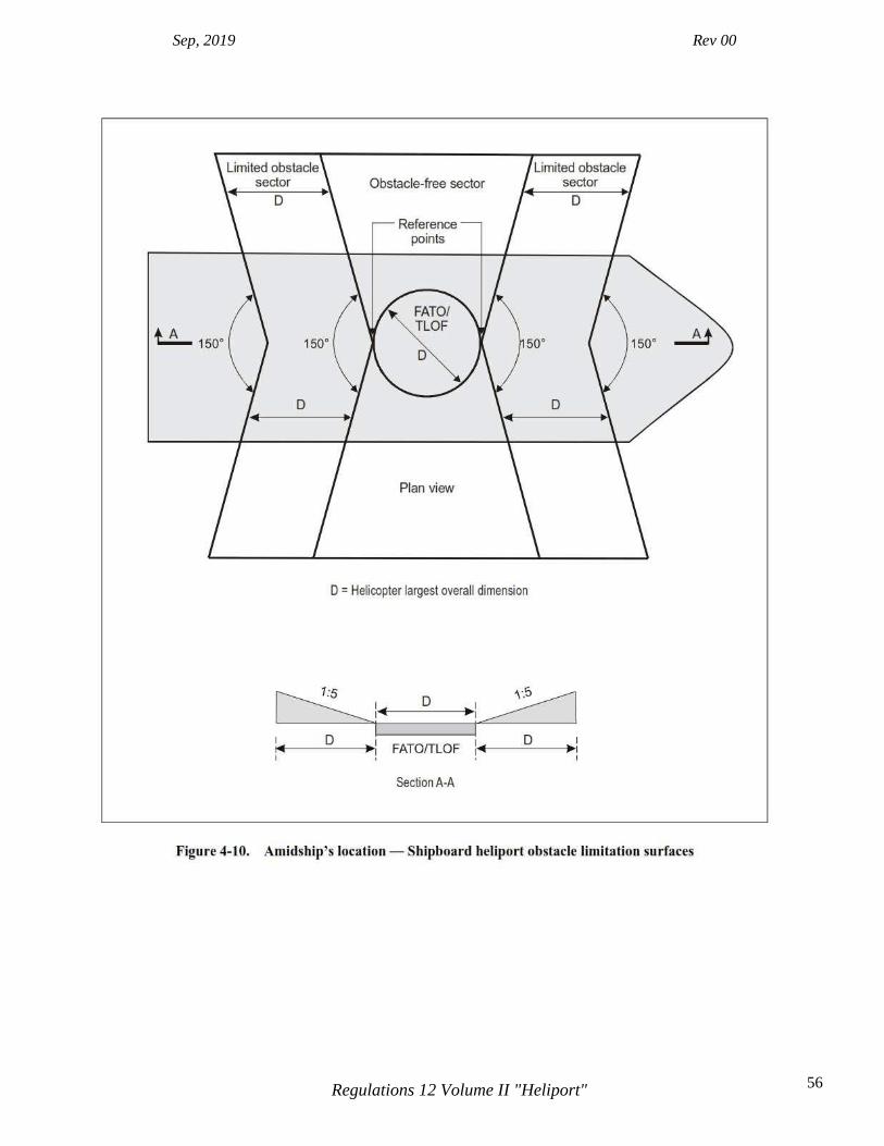
Sep, 2019 Rev 00
56 Regulations 12 Volume II "Heliport"

Sep, 2019 Rev 00
57 Regulations 12 Volume II "Heliport"
4.2.21 To provide further protection from obstacles fore and aft of the TLOF, rising surfaces with gradients of one unit vertically to five units horizontally shall extend from the entire length of the edges of the two 150-degree sectors. These surfaces shall extend for a horizontal distance equal to at least 1 D of the largest helicopter the TLOF is intended to serve and shall not be penetrated by any obstacle. (See Figure 4-10.) Non-purpose-built heliports
Ship’s side location
4.2.22 No objects shall be located within the TLOF except those aids essential for the safe operation of a helicopter (such as nets or lighting) and then only up to a maximum height of 2.5 cm. Such objects shall only be present if they do not represent a hazard to helicopters. 4.2.23 From the fore and aft mid-points of the D circle in two segments outside the circle, limited obstacle areas shall extend to the ship’s rail to a fore and aft distance of 1.5 times the fore- to-aft-dimension of the TLOF, located symmetrically about the athwartships bisector of the D circle.

Sep, 2019 Rev 00
58 Regulations 12 Volume II "Heliport"
Within these areas there shall be no objects rising above a maximum height of 25 cm above the level of the TLOF. (See Figure 4-11.) Such objects shall only be present if they do not represent a hazard to helicopters. 4.2.24 A limited obstacle sector horizontal surface shall be provided, at least 0.25 D beyond the diameter of the D circle, which shall surround the inboard sides of the TLOF to the fore and aft mid-points of the D circle The limited obstacle sector shall continue to the ship’s rail to a fore and aft distance of 2.0 times the fore-to-aft dimension of the TLOF, located symmetrically about the athwartships bisector of the D circle. Within this sector there shall be no objects rising above a maximum height of 25 cm above the level of the TLOF. Note.— Any objects located within the areas described in 4.2.23 and 4.2.24 that exceed the height of the TLOF are notified to the helicopter operator using a ship’s helicopter landing area plan. For notification purposes it may be necessary to consider immoveable objects beyond the limit of the surface prescribed in 4.2.24 particularly if objects are significantly higher than 25 cm and in close proximity to the boundary of the LOS. See the Heliport Manual (Doc 9261) for guidance.
Winching areas 4.2.25 An area designated for winching on-board ships shall be comprised of a circular clear zone of diameter 5m and extending from the perimeter of the clear zone, a concentric manoeuvring zone of diameter 2 D. (See Figure 4-12.) 4.2.26 The manoeuvring zone shall be comprised of two areas:
a. the inner manoeuvring zone extending from the perimeter of the clear zone and of a circle of diameter not less than 1.5 D; and
b. the outer manoeuvring zone extending from the perimeter of the inner
manoeuvring zone and of a circle of diameter not less than 2 D. 4.2.27 Within the clear zone of a designated winching area, no objects shall be located above the level of its surface. 4.2.28 Objects located within the inner manoeuvring zone of a designated winching area shall not exceed a height of 3m. 4.2.29 Objects located within the outer manoeuvring zone of a designated winching area shall not exceed a height of 6m. Note.— See the Heliport Manual (Doc 9261) for guidance.
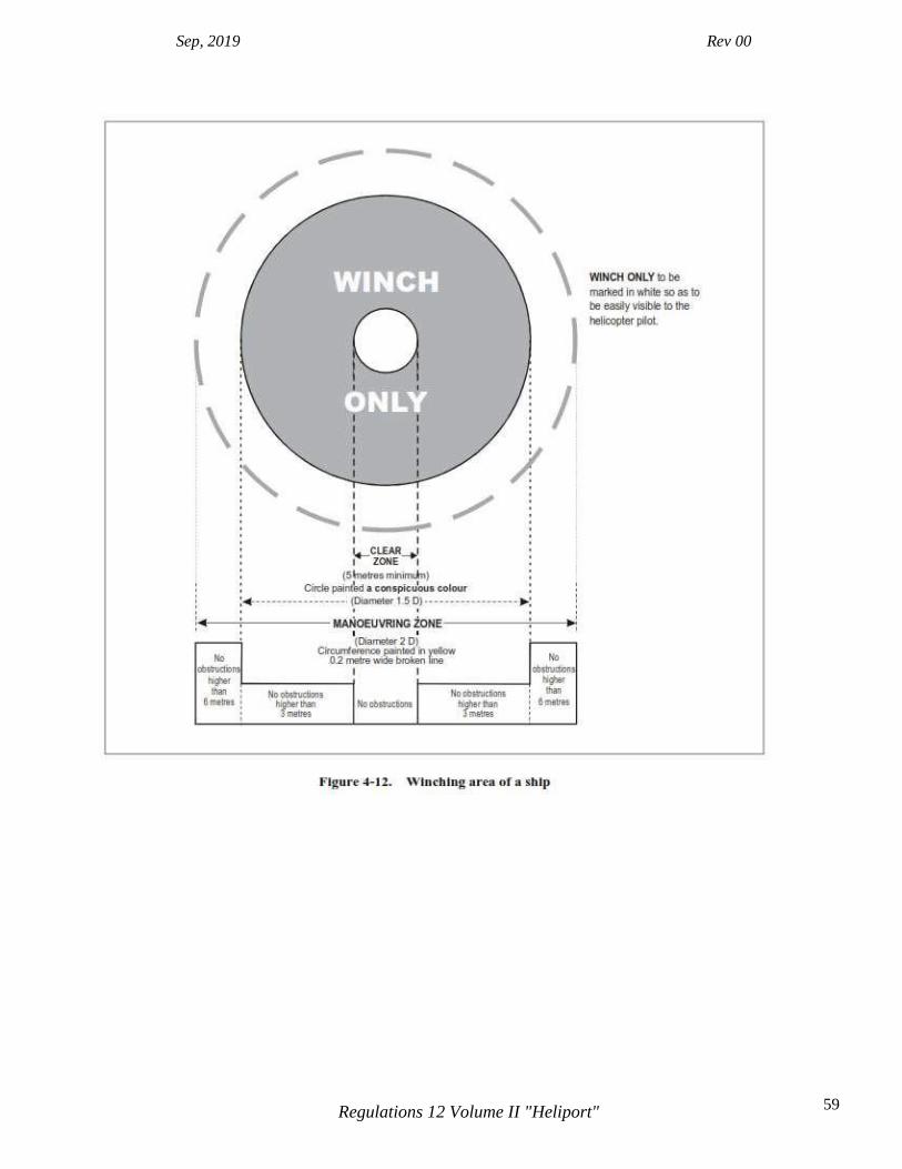
Sep, 2019 Rev 00
59 Regulations 12 Volume II "Heliport"
Sep, 2019 Rev 00
60 Regulations 12 Volume II "Heliport"
CHAPTER 5. VISUAL AIDS Note 1.— The procedures used by some helicopters require that they utilize a FATO having characteristics similar in shape to a runway for fixed wing aircraft. For the purpose of this chapter a FATO having characteristics similar in shape to a runway is considered as satisfying the concept for a “runway-type FATO”. For such arrangements it is sometimes necessary to provide specific markings to enable a pilot to distinguish a runway-type FATO during an approach. Appropriate markings are contained within sub-sections entitled “Runway-type FATOs”. The requirements applicable to all other types of FATOs are given within sub-sections entitled “All FATOs except runway-type FATOs”. Note 2.— It has been found that, on surfaces of light colour, the conspicuity of white and yellow markings can be improved by outlining them in black. Note 3.— Guidance is given in the Heliport Manual (Doc 9261) on marking the maximum allowable mass (5.2.3), the D-value (5.2.4) and, if required, the actual FATO dimension(s) (5.2.5) on the heliport surface to avoid confusion between markings where metric units are used and markings where imperial units are used. Note 4.— For a non-purpose-built heliport located on a ship’s side the surface colour of the main deck can vary from ship to ship and therefore some discretion may need to be exercised in the colour selection of heliport paint schemes; the objective being to ensure that the markings are conspicuous against the surface of the ship and the operating background.
5.1 Indicators 5.1.1 Wind direction indicators
Application 5.1.1.1 A heliport shall be equipped with at least one wind direction indicator.
Location 5.1.1.2 A wind direction indicator shall be located so as to indicate the wind conditions over the FATO and TLOF and in such a way as to be free from the effects of airflow disturbances caused by nearby objects or rotor downwash. It shall be visible from a helicopter in flight, in a hover or on the movement area. 5.1.1.3 Where a TLOF and/or FATO may be subject to a disturbed airflow, then additional wind direction indicators located close to the area should be provided to indicate the surface wind on the area. Note.— Guidance on the location of wind direction indicators is given in the Heliport Manual (Doc 9261).
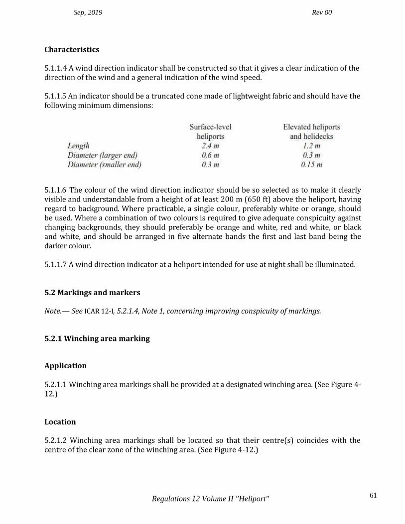
Sep, 2019 Rev 00
61 Regulations 12 Volume II "Heliport"
Characteristics 5.1.1.4 A wind direction indicator shall be constructed so that it gives a clear indication of the direction of the wind and a general indication of the wind speed. 5.1.1.5 An indicator should be a truncated cone made of lightweight fabric and should have the following minimum dimensions:
5.1.1.6 The colour of the wind direction indicator should be so selected as to make it clearly visible and understandable from a height of at least 200 m (650 ft) above the heliport, having regard to background. Where practicable, a single colour, preferably white or orange, should be used. Where a combination of two colours is required to give adequate conspicuity against changing backgrounds, they should preferably be orange and white, red and white, or black and white, and should be arranged in five alternate bands the first and last band being the darker colour. 5.1.1.7 A wind direction indicator at a heliport intended for use at night shall be illuminated.
5.2 Markings and markers Note.— See ICAR 12-I, 5.2.1.4, Note 1, concerning improving conspicuity of markings.
5.2.1 Winching area marking
Application 5.2.1.1 Winching area markings shall be provided at a designated winching area. (See Figure 4-12.)
Location 5.2.1.2 Winching area markings shall be located so that their centre(s) coincides with the centre of the clear zone of the winching area. (See Figure 4-12.)

Sep, 2019 Rev 00
62 Regulations 12 Volume II "Heliport"
Characteristics
5.2.1.3 Winching area markings shall comprise a winching area clear zone marking and a winching area manoeuvring zone marking. 5.2.1.4 A winching area clear zone marking shall consist of a solid circle of diameter not less than 5 m and of a conspicuous colour. 5.2.1.5 A winching area manoeuvring zone marking shall consist of a broken circle line of 30 cm in width and of a diameter not less than 2 D and be marked in a conspicuous colour. Within it “WINCH ONLY” shall be marked to be easily visible to the pilot.
5.2.2 Heliport identification marking
Application 5.2.2.1 Heliport identification markings shall be provided at a heliport.
Location — All FATOs except runway-type FATOs 5.2.2.2 A heliport identification marking shall be located at or near the centre of the FATO. Note 1.— If the touchdown/positioning marking is offset on a helideck, the heliport identification marking is established in the centre of the touchdown/positioning marking. Note 2.— On a FATO, which does not contain a TLOF and which is marked with an aiming point marking (see 5.2.8), except for a heliport at a hospital, the heliport identification marking is established in the centre of the aiming point marking as shown in Figure 5-1. 5.2.2.3 On a FATO which contains a TLOF, a heliport identification marking shall be located in the FATO so the position of it coincides with the centre of the TLOF.
Location — Runway-type FATOs 5.2.2.4 A heliport identification marking shall be located in the FATO and when used in conjunction with FATO designation markings, shall be displayed at each end of the FATO as shown in Figure 5-2.
Characteristics 5.2.2.5 A heliport identification marking, except for a heliport at a hospital, shall consist of a letter H, white in colour. The dimensions of the H marking shall be no less than those shown in Figure 5-3 and where the marking is used for a runway-type FATO, its dimensions shall be increased by a factor of 3 as shown in Figure 5-2.
Sep, 2019 Rev 00
63 Regulations 12 Volume II "Heliport"
5.2.2.6 A heliport identification marking for a heliport at a hospital shall consist of a letter H, red in color, on a white cross made of squares adjacent to each of the sides of a square containing the H as shown in Figure 5-3. 5.2.2.7 A heliport identification marking shall be oriented with the cross arm of the H at right angles to the preferred final approach direction. For a helideck the cross arm shall be on or parallel to the bisector of the obstacle-free sector. For a non-purpose-built shipboard heliport located on a ship’s side, the cross arm shall be parallel with the side of the ship. 5.2.2.8 On a helideck or a shipboard heliport where the D value is 16.0 m or larger, the size of the heliport identification H marking should have a height of 4 m with an overall width not exceeding 3 m and a stroke width not exceeding 0.75 m. Where the D value is less than 16.0 m, the size of the heliport identification H marking should have a height of 3 m with an overall width not exceeding 2.25 m and a stroke width not exceeding 0.5 m.
5.2.3 Maximum allowable mass marking
Application 5.2.3.1 A maximum allowable mass marking shall be displayed at an elevated heliport, a helideck and a shipboard heliport. Note: The aiming point, heliport identification and FATO perimeter markings are white and may be edged with a 10 cm black border to improve contrast 5.2.3.2 A maximum allowable mass marking should be displayed at a surface-level heliport.
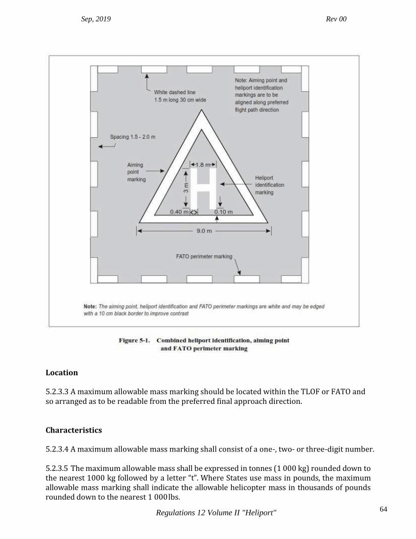
Sep, 2019 Rev 00
64 Regulations 12 Volume II "Heliport"
Location 5.2.3.3 A maximum allowable mass marking should be located within the TLOF or FATO and so arranged as to be readable from the preferred final approach direction.
Characteristics 5.2.3.4 A maximum allowable mass marking shall consist of a one-, two- or three-digit number. 5.2.3.5 The maximum allowable mass shall be expressed in tonnes (1 000 kg) rounded down to the nearest 1000 kg followed by a letter “t”. Where States use mass in pounds, the maximum allowable mass marking shall indicate the allowable helicopter mass in thousands of pounds rounded down to the nearest 1 000 lbs.

Sep, 2019 Rev 00
65 Regulations 12 Volume II "Heliport"
Note.— Where States express the maximum allowable mass in pounds, it is not appropriate to suffix with the letter “t” which is used only to indicate metric tonnes. Guidance on markings where States use imperial units is given in the Heliport Manual (Doc 9261).
5.2.3.6 The maximum allowable mass should be expressed to the nearest 100 kg. The marking should be presented to one decimal place and rounded to the nearest 100 kg followed by

Sep, 2019 Rev 00
66 Regulations 12 Volume II "Heliport"
the letter “t”. Where States use mass in pounds, the maximum allowable mass marking should indicate the allowable helicopter mass in hundreds of pounds rounded to the nearest 100 lb. 5.2.3.7 When the maximum allowable mass is expressed to 100 kg, the decimal place should be preceded with a decimal point marked with a 30 cm square.
All FATOs except runway-type FATOs 5.2.3.8 The numbers and the letter of the marking should have a colour contrasting with the background and should be in the form and proportion shown in Figure 5-4 for a FATO with a dimension of more than 30 m. For a FATO with a dimension of between 15 m to 30 m the height of the numbers and the letter of the marking should be a minimum of 90 cm, and for a FATO with a dimension of less than 15 m the height of the numbers and the letter of the marking should be a minimum of 60 cm, each with a proportional reduction in width and thickness. Runway-type FATOs 5.2.3.9 The numbers and the letter of the marking should have a colour contrasting with the background and should be in the form and proportion shown in Figure 5-4. 5.2.4 D-value marking Application
All FATOs except runway-type FATOs
5.2.4.1 The D-value marking shall be displayed at a helideck and at a shipboard heliport. Runway-type FATOs Note.—The D-value is not required to be marked on a heliport with a runway-type FATO. 5.2.4.2 The D-value marking should be displayed at surface-level and elevated heliports designed for helicopters operated in Performance Class 2 or 3. Location 5.2.4.3 A D-value marking shall be located within the TLOF or FATO and so arranged as to be readable from the preferred final approach direction. 5.2.4.4 Where there is more than one approach direction, additional D-value markings should be provided such that at least one D-value marking is readable from the final approach directions. For a non-purpose-built heliport located on a ship’s side, D-value markings should be provided on the perimeter of the D circle at the 2 o’clock, 10 o’clock and 12 o’clock positions when viewed from the side of the ship facing towards the centre line.
Sep, 2019 Rev 00
67 Regulations 12 Volume II "Heliport"
Characteristics 5.2.4.5 The D-value marking shall be white. The D-value marking shall be rounded to the nearest whole metre or foot with 0.5 rounded down. 5.2.4.6 The numbers of the marking should have a colour contrasting with the background and should be in the form and proportion shown in Figure 5-4 for a FATO with a dimension of more than 30 m. For a FATO with a dimension of between 15 m to 30 m the height of the numbers of the marking should be a minimum of 90 cm, and for a FATO with a dimension of less than 15 m the height of the numbers of the marking should be a minimum of 60 cm, each with a proportional reduction in width and thickness.

Sep, 2019 Rev 00
68 Regulations 12 Volume II "Heliport"
5.2.5 Final approach and take-off area dimension(s) marking
Application 5.2.5.1 The actual dimension(s) of the FATO intended to be used by helicopters operated in performance class 1 should be marked on the FATO. 5.2.5.2 If the actual dimension(s) of the FATO to be used by helicopters operated in performance class 2 or 3 is less than 1 D, the dimension(s) should be marked on the FATO.
Sep, 2019 Rev 00
69 Regulations 12 Volume II "Heliport"
Location 5.2.5.3 A FATO dimension marking shall be located within the FATO and so arranged as to be readable from the preferred final approach direction. Characteristics 5.2.5.4 The dimension(s) shall be rounded to the nearest metre or foot. Note.— If the FATO is rectangular both the length and width of the FATO relative to the preferred final approach direction is indicated.
All FATOs except runway-type FATOs 5.2.5.5 The numbers of the marking should have a colour contrasting with the background and should be in the form and proportion shown in Figure 5-4 for a FATO with a dimension of more than 30 m. For a FATO with a dimension between 15 m to 30 m the height of the numbers of the marking should be a minimum of 90 cm, and for a FATO with a dimension of less than 15 m the height of the numbers of the marking should be a minimum of 60 cm, each with a proportional reduction in width and thickness.
Runway-type FATOs 5.2.5.6 The numbers of the marking should have a colour contrasting with the background and should be in the form and proportion shown in Figure 5-4.
5.2.6 Final approach and take-off area perimeter marking or markers for surface-level heliports
Application 5.2.6.1 FATO perimeter marking or markers shall be provided at a surface-level heliport where the extent of the FATO is not self-evident. Location 5.2.6.2 The FATO perimeter marking or markers shall be located on the edge of the FATO.

Sep, 2019 Rev 00
70 Regulations 12 Volume II "Heliport"
Characteristics — Runway-type FATOs 5.2.6.3 The perimeter of the FATO shall be defined with markings or markers spaced at equal intervals of not more than 50 m with at least three markings or markers on each side including a marking or marker at each corner. 5.2.6.4 A FATO perimeter marking shall be a rectangular stripe with a length of 9 m or one- fifth of the side of the FATO which it defines and a width of 1 m. 5.2.6.5 FATO perimeter markings shall be white. 5.2.6.6 A FATO perimeter marker shall have dimensional characteristics as shown in Figure 5-5. 5.2.6.7 FATO perimeter markers shall be of colour(s) that contrast effectively against the operating background. 5.2.6.8 FATO perimeter markers should be a single colour, orange or red, or two contrasting colours, orange and white or, alternatively, red and white should be used except where such colours would merge with the background. Characteristics — All FATOs except runway-type FATOs 5.2.6.9 For an unpaved FATO the perimeter shall be defined with flush in-ground markers. The FATO perimeter markers shall be 30 cm in width, 1.5 m in length, and with end-to-end spacing of not less than 1.5 m and not more than 2 m. The corners of a square or rectangular FATO shall be defined. 5.2.6.10 For a paved FATO the perimeter shall be defined with a dashed line. The FATO perimeter marking segments shall be 30 cm in width, 1.5 m in length, and with end-to-end spacing of not less than 1.5 m and not more than 2 m. The corners of the square or rectangular FATO shall be defined. 5.2.6.11 FATO perimeter markings and flush in-ground markers shall be white.

Sep, 2019 Rev 00
71 Regulations 12 Volume II "Heliport"
5.2.7 Final approach and take-off area designation markings for runway-type FATOs
Application 5.2.7.1 A FATO designation marking should be provided at a heliport where it is necessary to designate the FATO to the pilot.
Location 5.2.7.2 A FATO designation marking shall be located at the beginning of the FATO as shown in Figure 5-2. Characteristics 5.2.7.3 A FATO designation marking shall consist of a two-digit number. The two-digit number shall be the whole number nearest the one-tenth of the magnetic North when viewed from the direction of approach. When the above rule would give a single digit number, it shall be preceded by a zero. The marking as shown in Figure 5-2, shall be supplemented by the heliport identification marking. 5.2.8 Aiming point marking Application 5.2.8.1 An aiming point marking should be provided at a heliport where it is necessary for a pilot to make an approach to a particular point above a FATO before proceeding to a TLOF.

Sep, 2019 Rev 00
72 Regulations 12 Volume II "Heliport"
Location — Runway-type FATOs 5.2.8.2 The aiming point marking shall be located within the FATO. Location — All FATOs except runway-type FATOs 5.2.8.3 The aiming point marking shall be located at the centre of the FATO as shown in Figure 5-1.
Characteristics 5.2.8.4 The aiming point marking shall be an equilateral triangle with the bisector of one of the angles aligned with the preferred approach direction. The marking shall consist of continuous white lines, and the dimensions of the marking shall conform to those shown in Figure 5-6.
Sep, 2019 Rev 00
73 Regulations 12 Volume II "Heliport"
5.2.9 Touchdown and lift-off area perimeter marking.
Application 5.2.9.1 A TLOF perimeter marking shall be displayed on a TLOF located in a FATO at a surface-level heliport if the perimeter of the TLOF is not self-evident. 5.2.9.2 A TLOF perimeter marking shall be displayed on an elevated heliport, a helideck and a shipboard heliport. 5.2.9.3 A TLOF perimeter marking should be provided on each TLOF collocated with a helicopter stand at a surface-level heliport.
Location 5.2.9.4 The TLOF perimeter marking shall be located along the edge of the TLOF.
Characteristics 5.2.9.5 A TLOF perimeter marking shall consist of a continuous white line with a width of at least 30 cm.
5.2.10 Touchdown/positioning marking
Application 5.2.10.1 A touchdown/positioning marking shall be provided where it is necessary for a helicopter to touch down and/or be accurately positioned by the pilot. A touchdown/positioning marking shall be provided on a helicopter stand designed for turning.
Location 5.2.10.2 A touchdown/positioning marking shall be located so that when the pilot’s seat is over the marking, the whole of the undercarriage will be within the TLOF and all parts of the helicopter will be clear of any obstacle by a safe margin. 5.2.10.3 On a heliport the centre of the touchdown/positioning marking shall be located at the centre of the TLOF, except the centre of the touchdown/positioning marking may be offset away from the centre of the TLOF where an aeronautical study indicates such offsetting to be necessary and providing that a marking so offset would not adversely affect safety. For a helicopter stand designed for hover turning, the touchdown/positioning marking shall be located in the centre of the central zone. (See Figure 3-4.) 5.2.10.4 On a helideck the centre of the touchdown marking shall be located at the centre of the FATO, except that the marking may be offset away from the origin of the obstacle-free sector
Sep, 2019 Rev 00
74 Regulations 12 Volume II "Heliport"
by no more than 0.1 D where an aeronautical study indicates such offsetting to be necessary and that a marking so offset would not adversely affect the safety. Note.— See the Heliport Manual (Doc 9261) for guidance.
Characteristics 5.2.10.5 A touchdown/positioning marking shall be a yellow circle and have a line width of at least 0.5 m. For a helideck and a purpose-built shipboard heliport with a D value of 16.0m or larger, the line width shall be at least 1 m. 5.2.10.6 The inner diameter of the touchdown/positioning marking shall be 0.5 D of the largest helicopter the TLOF and/or the helicopter stand is intended to serve.
5.2.11 Heliport name marking Application 5.2.11.1 A heliport name marking should be provided at a heliport and helideck where there is insufficient alternative means of visual identification.
Location 5.2.11.2 The heliport name marking should be displayed on the heliport so as to be visible, as far as practicable, at all angles above the horizontal. Where an obstacle sector exists on a helideck the marking should be located on the obstacle side of the heliport identification marking. For a non- purpose-built heliport located on a ship’s side the marking should be located on the inboard side of the heliport identification marking in the area between the TLOF perimeter marking and the boundary of the LOS.
Characteristics 5.2.11.3 A heliport name marking shall consist of the name or the alphanumeric designator of the heliport as used in the radio (R/T) communications. 5.2.11.4 A heliport name marking intended for use at night or during conditions of poor visibility should be illuminated, either internally or externally. Runway-type FATOs

Sep, 2019 Rev 00
75 Regulations 12 Volume II "Heliport"
5.2.11.5 The characters of the marking should be not less than 3 m in height.
All FATOs except runway-type FATOs. 5.2.11.6 The characters of the marking should be not less than 1.5 m in height at surface- level heliports and not less than 1.2 m on elevated heliports, helidecks and shipboard heliports. The colour of the marking should contrast with the background and preferably be white.
5.2.12 Helideck obstacle-free sector (chevron) marking
Application 5.2.12.1 A helideck with adjacent obstacles that penetrate above the level of the helideck shall have an obstacle-free sector marking. Location 5.2.12.2 A helideck obstacle-free sector marking shall be located, where practicable, at a distance from the centre of the TLOF equal to the radius of the largest circle that can be drawn in the TLOF or 0.5 D, whichever is greater. Note.— Where the Point of Origin is outside the TLOF, and it is not practicable to physically paint the chevron, the chevron is relocated to the TLOF perimeter on the bisector of the OFS. In this case the distance and direction of displacement, along with the attention getting “WARNING DISPLACED CHEVRON”, with the distance and direction of displacement, is marked in a box beneath the chevron in black characters not less than 10 cm high — an example Figure is given in the Heliport Manual (Doc 9261). Characteristics 5.2.12.3 The helideck obstacle-free sector marking shall indicate the location of the obstacle- free sector and the directions of the limits of the sector. Note.— Example figures are given in the Heliport Manual (Doc 9261).
5.2.12.4 The height of the chevron shall not be less than 30 cm.
5.2.12.5 The chevron shall be marked in a conspicuous colour.
5.2.12.6 The colour of the chevron should be black.
Sep, 2019 Rev 00
76 Regulations 12 Volume II "Heliport"
5.2.13 Helideck and shipboard heliport surface marking
Application 5.2.13.1 A surface marking should be provided to assist the pilot to identify the location of the helideck or shipboard heliport during an approach by day. Location 5.2.13.2 A surface marking should be applied to the dynamic load bearing area bounded by the TLOF perimeter marking.
Characteristics 5.2.13.3 The helideck or shipboard heliport surface bounded by the TLOF perimeter marking should be of dark green using a high friction coating. Note.— Where the application of a surface coating may have a degrading effect on friction qualities the surface might not be painted. In such cases the best operating practice to enhance the conspicuity of markings is to outline deck markings with a contrasting colour.
5.2.14 Helideck prohibited landing sector markings
Application 5.2.14.1 Helideck prohibited landing sector markings should be provided where it is necessary to prevent the helicopter from landing within specified headings.
Location 5.2.14.2 The prohibited landing sector markings shall be located on the touchdown/positioning marking to the edge of the TLOF, within the relevant headings.
Characteristics

Sep, 2019 Rev 00
77 Regulations 12 Volume II "Heliport"
5.2.14.3 The prohibited landing sector markings shall be indicated by white and red hatched markings as shown in Figure 5-7. Note.— Prohibited landing sector markings, where deemed necessary, are applied to indicate a range of helicopter headings that are not to be used by a helicopter when landing. This is to ensure that the nose of the helicopter is kept clear of the hatched markings during the manoeuvre to land.
5.2.15 Helicopter ground taxiway markings and markers Note 1.— The specifications for taxi-holding position markings in Annex 14, Volume I, 5.2.10 are equally applicable to taxiways intended for ground taxiing of helicopters. Note 2.— Ground taxi-routes are not required to be marked.

Sep, 2019 Rev 00
78 Regulations 12 Volume II "Heliport"
Application 5.2.15.1 The centre line of a helicopter ground taxiway should be identified with a marking, and the edges of a helicopter ground taxiway, if not self-evident, should be identified with markers or markings.
Location 5.2.15.2 Helicopter ground taxiway markings shall be along the centre line and, if required, along the edges of a helicopter ground taxiway. 5.2.15.3 Helicopter ground taxiway edge markers shall be located at a distance of 0.5 m to 3 m beyond the edge of the helicopter ground taxiway. 5.2.15.4 Helicopter ground taxiway edge markers, where provided, shall be spaced at intervals of not more than 15 m on each side of straight sections and 7.5 m on each side of curved sections with a minimum of four equally spaced markers per section.
Characteristics 5.2.15.5 A helicopter ground taxiway centre line marking shall be a continuous yellow line 15 cm in width. 5.2.15.6 Helicopter ground taxiway edge markings shall be a continuous double yellow line, each 15 cm in width, and spaced 15 cm apart (nearest edge to nearest edge). Note.— Signage may be required on an aerodrome where it is necessary to indicate that a helicopter ground taxiway is suitable only for the use of helicopters. 5.2.15.7 A helicopter ground taxiway edge marker shall be frangible. 5.2.15.8 A helicopter ground taxiway edge marker shall not exceed a plane originating at a height of 25 cm above the plane of the helicopter ground taxiway, at a distance of 0.5 m from the edge of the helicopter ground taxiway and sloping upwards and outwards at a gradient of 5 per cent to a distance of 3 m beyond the edge of the helicopter ground taxiway. 5.2.15.9 A helicopter ground taxiway edge marker shall be blue. Note 1.— Guidance on suitable edge markers is given in the Heliport Manual (Doc 9261). Note 2.— If blue markers are used on an aerodrome, signage may be required to indicate that the helicopter ground taxiway is suitable only for helicopters. 5.2.15.10 If the helicopter ground taxiway is to be used at night, the edge markers shall be internally illuminated or retro-reflective.
Sep, 2019 Rev 00
79 Regulations 12 Volume II "Heliport"
5.2.16 Helicopter air taxiway markings and markers Note.— Air taxi-routes are not required to be marked.
Application 5.2.16.1 The centre line of a helicopter air taxiway or, if not self-evident, the edges of a helicopter air taxiway should be identified with markers or markings.
Location 5.2.16.2 A helicopter air taxiway centre line marking or flush in-ground centre line marker shall be located along the centre line of the helicopter air taxiway. 5.2.16.3 Helicopter air taxiway edge markings shall be located along the edges of a helicopter air taxiway. 5.2.16.4 Helicopter air taxiway edge markers shall be located at a distance of 1 m to 3 m beyond the edge of the helicopter air taxiway. 5.2.16.5 Helicopter air taxiway edge markers should not be located at a distance of less than
0.5 times the largest overall width of the helicopter for which it is designed from the centre line of the helicopter air taxiway.
Characteristics 5.2.16.6 A helicopter air taxiway centre line, when on a paved surface, shall be marked with a continuous yellow line 15 cm in width. 5.2.16.7 The edges of a helicopter air taxiway, when on a paved surface, shall be marked with continuous double yellow lines each 15 cm in width, and spaced 15 cm apart (nearest edge to nearest edge). Note.— Where there is potential for a helicopter air taxiway to be confused with a helicopter ground taxiway, signage may be required to indicate the mode of taxi operations that are permitted. 5.2.16.8 A helicopter air taxiway centre line, when on an unpaved surface that will not accommodate painted markings, shall be marked with flush in-ground 15 cm wide and approximately 1.5 m in length yellow markers, spaced at intervals of not more than 30 m on straight sections and not more than 15 m on curves, with a minimum of four equally spaced markers per section.
Sep, 2019 Rev 00
80 Regulations 12 Volume II "Heliport"
5.2.16.9 Helicopter air taxiway edge markers, where provided, shall be spaced at intervals of not more than 30 m on each side of straight sections and not more than 15 m on each side of curves, with a minimum of four equally spaced markers per section. 5.2.16.10 Helicopter air taxiway edge markers shall be frangible. 5.2.16.11 Helicopter air taxiway edge markers shall not penetrate a plane originating at a height of 25 cm above the plane of the helicopter air taxiway, at a distance of 1 m from the edge of the helicopter air taxiway and sloping upwards and outwards at a gradient of 5 per cent to a distance of 3 m beyond the edge of the helicopter air taxiway. 5.2.16.12 Helicopter air taxiway edge markers should not penetrate a plane originating at a height of 25 cm above the plane of the helicopter air taxiway, at a distance of 0.5 times the largest overall width of the helicopter for which it is designed from the centre line of the helicopter air taxiway, and sloping upwards and outwards at a gradient of 5 per cent. 5.2.16.13 A helicopter air taxiway edge marker shall be of colour(s) that contrast effectively against the operating background. The colour red shall not be used for markers. Note.— Guidance for suitable edge markers is given in the Heliport Manual (Doc 9261). 5.2.16.14 If the helicopter air taxiway is to be used at night, helicopter air taxiway edge markers shall be either internally illuminated or retro-reflective.
5.2.17 Helicopter stand markings
Application 5.2.17.1 A helicopter stand perimeter marking shall be provided on a helicopter stand designed for turning. If a helicopter stand perimeter marking is not practicable, a central zone perimeter marking shall be provided instead if the perimeter of the central zone is not self-evident. 5.2.17.2 For a helicopter stand intended to be used for taxi-through and which does not allow the helicopter to turn, a stop line shall be provided. 5.2.17.3 Alignment lines and lead-in/lead-out lines should be provided on a helicopter stand. Note 1.— See Figure 5-8. Note 2.— Helicopter stand identification markings may be provided where there is a need to identify individual stands.

Sep, 2019 Rev 00
81 Regulations 12 Volume II "Heliport"
Note 3.— Additional markings relating to stand size may be provided. See the Heliport Manual (Doc 9261).
Location
5.2.17.4 A helicopter stand perimeter marking on a helicopter stand designed for turning or, a central zone perimeter marking, shall be concentric with the central zone of the stand. 5.2.17.5 For a helicopter stand intended to be used for taxi-through and which does not allow the helicopter to turn, a stop line shall be located on the helicopter ground taxiway axis at right angles to the centre line. 5.2.17.6 Alignment lines and lead-in/lead-out lines shall be located as shown in Figure 5-8.

Sep, 2019 Rev 00
82 Regulations 12 Volume II "Heliport"
Characteristics 5.2.17.7 A helicopter stand perimeter marking shall be a yellow circle and have a line width of 15 cm. 5.2.17.8 A central zone perimeter marking shall be a yellow circle and have a line width of 15 cm, except when the TLOF is collocated with a helicopter stand, the characteristics of the TLOF perimeter markings shall apply. 5.2.17.9 For a helicopter stand intended to be used for taxi-through and which does not allow the helicopter to turn, a yellow stop line shall not be less than the width of the helicopter ground taxiway and have a line thickness of 50 cm. 5.2.17.10 Alignment lines and lead-in/lead-out lines shall be continuous yellow lines and have a width of 15 cm. 5.2.17.11 Curved portions of alignment lines and lead-in/lead-out lines shall have radii appropriate to the most demanding helicopter type the helicopter stand is intended to serve. 5.2.17.12 Stand identification markings shall be marked in a contrasting colour so as to be easily readable. Note 1.— Where it is intended that helicopters proceed in one direction only, arrows indicating the direction to be followed may be added as part of the alignment lines. Note 2.— The characteristics of markings related to the stand size and alignment and lead- in/lead-out lines are illustrated in Figure 5-8.
5.2.18 Flight path alignment guidance marking
Application 5.2.18.1 Flight path alignment guidance marking(s) should be provided at a heliport where it is desirable and practicable to indicate available approach and/or departure path direction(s). Note.— The flight path alignment guidance marking can be combined with a flight path alignment guidance lighting system described in 5.3.4.
Location 5.2.18.2 The flight path alignment guidance marking shall be located in a straight line along the direction of approach and/or departure path on one or more of the TLOF, FATO, safety area or any suitable surface in the immediate vicinity of the FATO or safety area.

Sep, 2019 Rev 00
83 Regulations 12 Volume II "Heliport"
Characteristics 5.2.18.3 A flight path alignment guidance marking shall consist of one or more arrows marked on the TLOF, FATO and/or safety area surface as shown in Figure 5-9. The stroke of the arrow(s) shall be 50 cm in width and at least 3 m in length. When combined with a flight path alignment guidance lighting system it shall take the form shown in Figure 5-9 which includes the scheme for marking ‘heads of the arrows’ which are constant regardless of stroke length. Note.— In the case of a flight path limited to a single approach direction or single departure direction, the arrow marking may be unidirectional. In the case of a heliport with only a single approach/departure path available, one bidirectional arrow is marked. 5.2.18.4 The markings should be in a colour which provides good contrast against the background colour of the surface on which they are marked, preferably white.
5.3 Lights
5.3.1 General
Note 1.— See Annex 14, Volume I, 5.3.1, concerning specifications on screening of non- aeronautical ground lights, and design of elevated and inset lights.
Sep, 2019 Rev 00
84 Regulations 12 Volume II "Heliport"
Note 2.— In the case of helidecks and heliports located near navigable waters, consideration needs to be given to ensuring that aeronautical ground lights do not cause confusion to mariners. Note 3.— As helicopters will generally come very close to extraneous light sources, it is particularly important to ensure that, unless such lights are navigation lights exhibited in accordance with international regulations, they are screened or located so as to avoid direct and reflected glare. Note 4.— Specifications in sections 5.3.4, 5.3.6, 5.3.7, and 5.3.8 are designed to provide effective lighting systems based on night conditions. Where lights are to be used in conditions other than night (i.e. day or twilight) it may be necessary to increase the intensity of the lighting to maintain effective visual cues by use of a suitable brilliancy control. Guidance is provided in the Aerodrome Design Manual (Doc 9157), Part 4 — Visual Aids.
5.3.2 Heliport beacon
Application
5.3.2.1 A heliport beacon should be provided at a heliport where:
a. long-range visual guidance is considered necessary and is not provided by other visual means; or
b. identification of the heliport is difficult due to surrounding lights.
Location 5.3.2.2 The heliport beacon shall be located on or adjacent to the heliport preferably at an elevated position and so that it does not dazzle a pilot at short range. Note.— Where a heliport beacon is likely to dazzle pilots at short range, it may be switched off during the final stages of the approach and landing.
Characteristics 5.3.2.3 The heliport beacon shall emit repeated series of equispaced short duration white flashes in the format in Figure 5-10. 5.3.2.4 The light from the beacon shall show at all angles of azimuth. 5.3.2.5 The effective light intensity distribution of each flash should be as shown in Figure 5-11, Illustration 1.

Sep, 2019 Rev 00
85 Regulations 12 Volume II "Heliport"
Note.— Where brilliancy control is desired, settings of 10 per cent and 3 per cent have been found to be satisfactory. In addition, shielding may be necessary to ensure that pilots are not dazzled during the final stages of the approach and landing.
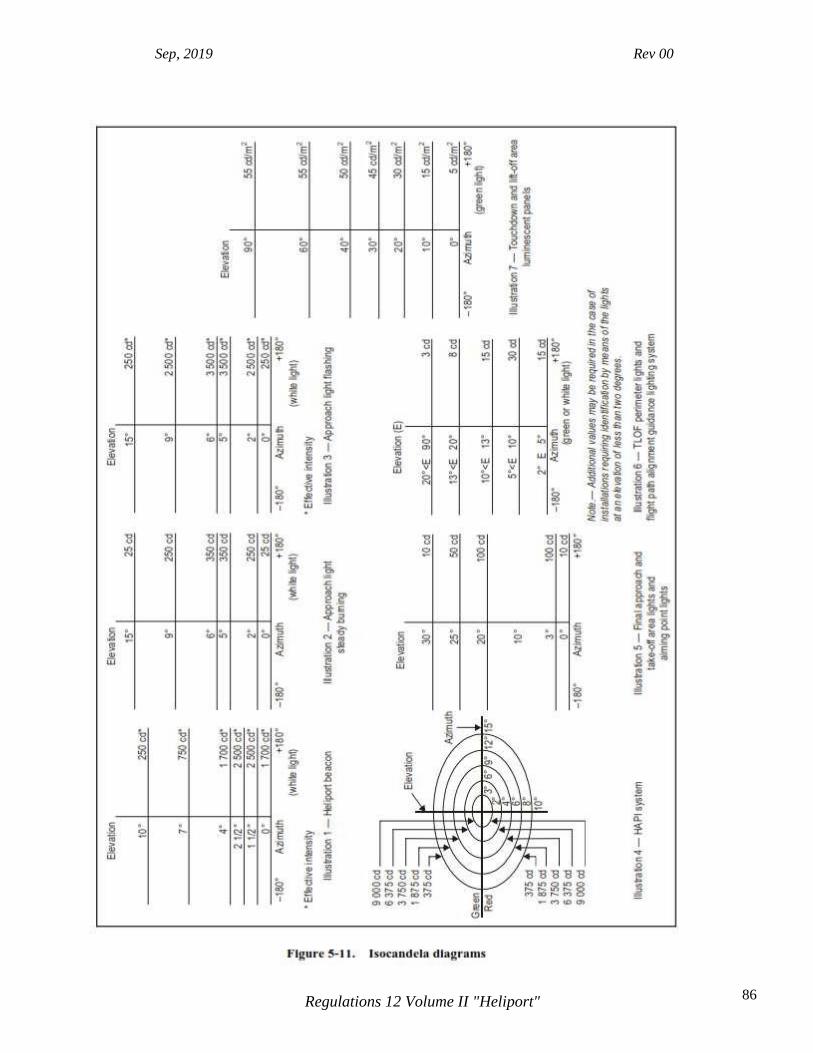
Sep, 2019 Rev 00
86 Regulations 12 Volume II "Heliport"

Sep, 2019 Rev 00
87 Regulations 12 Volume II "Heliport"
5.3.3 Approach lighting system
Application 5.3.3.1 An approach lighting system should be provided at a heliport where it is desirable and practicable to indicate a preferred approach direction. Location 5.3.3.2 The approach lighting system shall be located in a straight line along the preferred direction of approach.
Characteristics 5.3.3.3 An approach lighting system should consist of a row of three lights spaced uniformly at 30 m intervals and of a crossbar 18 m in length at a distance of 90 m from the perimeter of the FATO as shown in Figure 5-12. The lights forming the crossbar should be as nearly as practicable in a horizontal straight line at right angles to, and bisected by, the line of the centre line lights and spaced at 4.5 m intervals. Where there is the need to make the final approach course more conspicuous, additional lights spaced uniformly at 30 m intervals should be added beyond the crossbar. The lights beyond the crossbar may be steady or sequenced flashing, depending upon the environment. Note.— Sequenced flashing lights may be useful where identification of the approach lighting system is difficult due to surrounding lights. 5.3.3.4 The steady lights shall be omnidirectional white lights. 5.3.3.5 Sequenced flashing lights shall be omnidirectional white lights. 5.3.3.6 The flashing lights should have a flash frequency of one per second and their light distribution should be as shown in Figure 5-11, Illustration 3. The flash sequence should commence from the outermost light and progress towards the crossbar.
Sep, 2019 Rev 00
88 Regulations 12 Volume II "Heliport"
5.3.3.7 A suitable brilliancy control should be incorporated to allow for adjustment of light intensity to meet the prevailing conditions. Note.— The following intensity settings have been found suitable: a) steady lights — 100 per cent, 30 per cent and 10 per cent; and b) flashing lights — 100 per cent, 10 per cent and 3 per cent.
5.3.4 Flight path alignment guidance lighting system
Application 5.3.4.1 Flight path alignment guidance lighting system(s) should be provided at a heliport where it is desirable and practicable to indicate available approach and/or departure path direction(s). Note.— The flight path alignment guidance lighting can be combined with a flight path alignment guidance marking(s) described in 5.2.18.
Location 5.3.4.2 The flight path alignment guidance lighting system shall be in a straight line along the direction(s) of approach and/or departure path on one or more of the TLOF, FATO, safety area or any suitable surface in the immediate vicinity of the FATO, TLOF or safety area. 5.3.4.3 If combined with a flight path alignment guidance marking, as far as is practicable the lights should be located inside the “arrow” markings. Characteristics 5.3.4.4 A flight path alignment guidance lighting system should consist of a row of three or more lights spaced uniformly a total minimum distance of 6 m. Intervals between lights should not be less than 1.5 m and should not exceed 3 m. Where space permits there should be 5 lights. (See Figure 5-9.) Note.— The number of lights and spacing between these lights may be adjusted to reflect the space available. If more than one flight path alignment system is used to indicate available approach and/or departure path direction(s), the characteristics for each system are typically kept the same. (See Figure 5-9.) 5.3.4.5 The lights shall be steady omnidirectional inset white lights. 5.3.4.6 The distribution of the lights should be as indicated in Figure 5-11, Illustration 6.
Sep, 2019 Rev 00
89 Regulations 12 Volume II "Heliport"
5.3.4.7 A suitable control should be incorporated to allow for adjustment of light intensity to meet the prevailing conditions and to balance the flight path alignment guidance lighting system with other heliport lights and general lighting that may be present around the heliport.
5.3.5 Visual alignment guidance system
Application 5.3.5.1 A visual alignment guidance system should be provided to serve the approach to a heliport where one or more of the following conditions exist especially at night:
a. obstacle clearance, noise abatement or traffic control procedures require a particular direction to be flown;
b. the environment of the heliport provides few visual surface cues; and
c. it is physically impracticable to install an approach lighting system.
Location 5.3.5.2 The visual alignment guidance system shall be located such that a helicopter is guided along the prescribed track towards the FATO. 5.3.5.3 The system should be located at the downwind edge of the FATO and aligned along the preferred approach direction. 5.3.5.4 The light units shall be frangible and mounted as low as possible. 5.3.5.5 Where the lights of the system need to be seen as discrete sources, light units shall be located such that at the extremes of system coverage the angle subtended between units as seen by the pilot shall not be less than 3 minutes of arc. 5.3.5.6 The angles subtended between light units of the system and other units of comparable or greater intensities shall also be not less than 3 minutes of arc. Note.— Requirements of 5.3.5.5 and 5.3.5.6 can be met for lights on a line normal to the line of sight if the light units are separated by 1 m for every kilometre of viewing range.
Signal format

Sep, 2019 Rev 00
90 Regulations 12 Volume II "Heliport"
5.3.5.7 The signal format of the alignment guidance system shall include a minimum of three discrete signal sectors providing “offset to the right”, “on track” and “offset to the left” signals. 5.3.5.8 The divergence of the “on track” sector of the system shall be as shown in Figure 5- 13. 5.3.5.9 The signal format shall be such that there is no possibility of confusion between the system and any associated visual approach slope indicator or other visual aids. 5.3.5.10 The system shall avoid the use of the same coding as any associated visual approach slope indicator. 5.3.5.11 The signal format shall be such that the system is unique and conspicuous in all operational environments. 5.3.5.12 The system shall not significantly increase the pilot workload.
Light distribution 5.3.5.13 The usable coverage of the visual alignment guidance system shall be equal to or better than that of the visual approach slope indicator system with which it is associated. 5.3.5.14 A suitable intensity control shall be provided so as to allow adjustment to meet the prevailing conditions and to avoid dazzling the pilot during approach and landing.
Approach track and azimuth setting 5.3.5.15 A visual alignment guidance system shall be capable of adjustment in azimuth to within ±5 minutes of arc of the desired approach path. 5.3.5.16 The angle of the azimuth guidance system shall be such that during an approach the pilot of a helicopter at the boundary of the “on track” signal will clear all objects in the approach area by a safe margin. 5.3.5.17 The characteristics of the obstacle protection surface specified in 5.3.6.23, Table 5-1 and Figure 5-14 shall equally apply to the system.

Sep, 2019 Rev 00
91 Regulations 12 Volume II "Heliport"
Characteristics of the visual alignment guidance system 5.3.5.18 In the event of the failure of any component affecting the signal format the system shall be automatically switched off. 5.3.5.19 The light units shall be so designed that deposits of condensation, ice, dirt, etc., on optically transmitting or reflecting surfaces will interfere to the least possible extent with the light signal and will not cause spurious or false signals to be generated.

Sep, 2019 Rev 00
92 Regulations 12 Volume II "Heliport"
5.3.6 Visual approach slope indicator Application 5.3.6.1 A visual approach slope indicator should be provided to serve the approach to a heliport, whether or not the heliport is served by other visual approach aids or by non-visual aids, where one or more of the following conditions exist especially at night:
a. obstacle clearance, noise abatement or traffic control procedures require a particular slope to be flown;
b. the environment of the heliport provides few visual surface cues; and
c. the characteristics of the helicopter require a stabilized approach.
5.3.6.2 The standard visual approach slope indicator systems for helicopter operations shall consist of the following:

Sep, 2019 Rev 00
93 Regulations 12 Volume II "Heliport"
a. PAPI and APAPI systems conforming to the specifications contained in Annex 14, Volume I, 5.3.5.23 to 5.3.5.40 inclusive, except that the angular size of the on-slope sector of the systems shall be increased to 45 minutes; or
b. helicopter approach path indicator (HAPI) system conforming to the specifications in
5.3.6.6 to 5.3.6.21 inclusive. Location 5.3.6.3 A visual approach slope indicator shall be located such that a helicopter is guided to the desired position within the FATO and so as to avoid dazzling the pilot during final approach and landing. 5.3.6.4 A visual approach slope indicator should be located adjacent to the nominal aiming point and aligned in azimuth with the preferred approach direction. 5.3.6.5 The light unit(s) shall be frangible and mounted as low as possible.
HAPI signal format 5.3.6.6 The signal format of the HAPI shall include four discrete signal sectors, providing an “above slope”, an “on slope”, a “slightly below” and a “below slope” signal. 5.3.6.7 The signal format of the HAPI shall be as shown in Figure 5-15, Illustrations A and B. Note.— Care is required in the design of the unit to minimize spurious signals between the signal sectors and at the azimuth coverage limits. 5.3.6.8 The signal repetition rate of the flashing sector of the HAPI shall be at least 2 Hz. 5.3.6.9 The on-to-off ratio of pulsing signals of the HAPI should be 1 to 1, and the modulation depth should be at least 80 per cent. 5.3.6.10 The angular size of the “on-slope” sector of the HAPI shall be 45 minutes.
5.3.6.11 The angular size of the “slightly below” sector of the HAPI shall be 15 minutes.
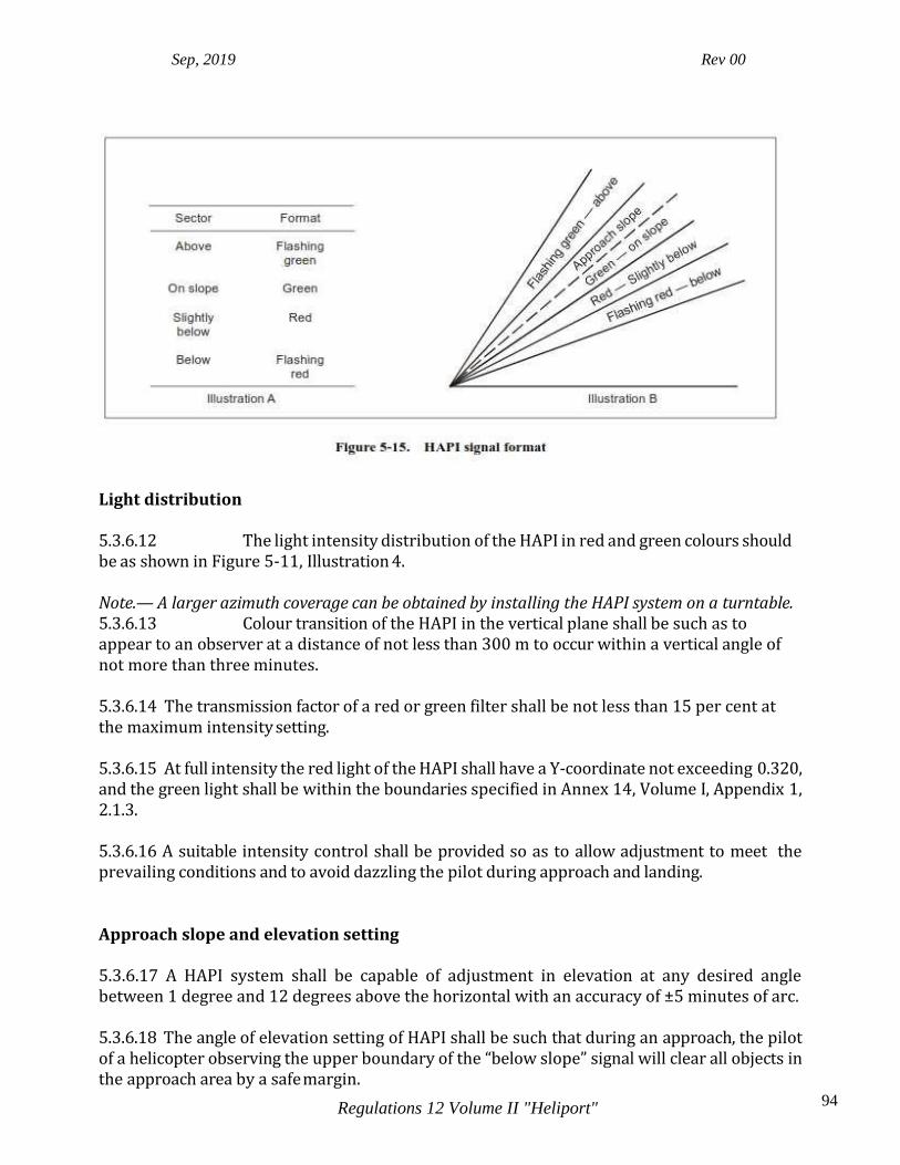
Sep, 2019 Rev 00
94 Regulations 12 Volume II "Heliport"
Light distribution 5.3.6.12 The light intensity distribution of the HAPI in red and green colours should be as shown in Figure 5-11, Illustration 4. Note.— A larger azimuth coverage can be obtained by installing the HAPI system on a turntable. 5.3.6.13 Colour transition of the HAPI in the vertical plane shall be such as to appear to an observer at a distance of not less than 300 m to occur within a vertical angle of not more than three minutes. 5.3.6.14 The transmission factor of a red or green filter shall be not less than 15 per cent at the maximum intensity setting. 5.3.6.15 At full intensity the red light of the HAPI shall have a Y-coordinate not exceeding 0.320, and the green light shall be within the boundaries specified in Annex 14, Volume I, Appendix 1, 2.1.3. 5.3.6.16 A suitable intensity control shall be provided so as to allow adjustment to meet the prevailing conditions and to avoid dazzling the pilot during approach and landing.
Approach slope and elevation setting 5.3.6.17 A HAPI system shall be capable of adjustment in elevation at any desired angle between 1 degree and 12 degrees above the horizontal with an accuracy of ±5 minutes of arc. 5.3.6.18 The angle of elevation setting of HAPI shall be such that during an approach, the pilot of a helicopter observing the upper boundary of the “below slope” signal will clear all objects in the approach area by a safe margin.

Sep, 2019 Rev 00
95 Regulations 12 Volume II "Heliport"
Characteristics of the light unit 5.3.6.19 The system shall be so designed that:
a. in the event the vertical misalignment of a unit exceeds ±0.5 degrees (±30 minutes), the system will switch off automatically; and
b. if the flashing mechanism fails, no light will be emitted in the failed flashing sector(s).
5.3.6.20 The light unit of the HAPI shall be so designed that deposits of condensation, ice, dirt, etc., on optically transmitting or reflecting surfaces will interfere to the least possible extent with the light signal and will not cause spurious or false signals to be generated. 5.3.6.21 A HAPI system intended for installation on a floating helideck should afford a stabilization of the beam to an accuracy of ± 1/4 degree within ± 3-degree pitch and roll movement of the heliport. Obstacle protection surface Note.— The following specifications apply to PAPI, APAPI and HAPI. 5.3.6.22 An obstacle protection surface shall be established when it is intended to provide a visual approach slope indicator system. 5.3.6.23 The characteristics of the obstacle protection surface, i.e. origin, divergence, length and slope, shall correspond to those specified in the relevant column of Table 5-1 and in Figure 5-14. 5.3.6.24 New objects or extensions of existing objects shall not be permitted above an obstacle protection surface except when, in the opinion of the appropriate authority, the new object or extension would be shielded by an existing immovable object. Note.— Circumstances in which the shielding principle may reasonably be applied are described in the Airport Services Manual, Part 6 (Doc 9137). 5.3.6.25 Existing objects above an obstacle protection surface shall be removed except when, in the opinion of the appropriate authority, the object is shielded by an existing immovable object, or after aeronautical study it is determined that the object would not adversely affect the safety of operations of helicopters. 5.3.6.26 Where an aeronautical study indicates that an existing object extending above an obstacle protection surface could adversely affect the safety of operations of helicopters, one or more of the following measures shall be taken:
a. suitably raise the approach slope of the system;
Sep, 2019 Rev 00
96 Regulations 12 Volume II "Heliport"
b. reduce the azimuth spread of the system so that the object is outside the confines of the beam;
c. displace the axis of the system and its associated obstacle protection surface by no
more than 5 degrees;
d. suitably displace the FATO; and
e. install a visual alignment guidance system specified in 5.3.5. Note.— Guidance on this issue is contained in the Heliport Manual (Doc 9261).
5.3.7 Final approach and take-off area lighting systems for surface-level heliports
Application 5.3.7.1 Where a FATO is established at a surface-level heliport on ground intended for use at night, FATO lights shall be provided except that they may be omitted where the FATO and the TLOF are nearly coincidental or the extent of the FATO is self-evident.
Location 5.3.7.2 FATO lights shall be placed along the edges of the FATO. The lights shall be uniformly spaced as follows:
a. for an area in the form of a square or rectangle, at intervals of not more than 50 m with a minimum of four lights on each side including a light at each corner; and
b. for any other shaped area, including a circular area, at intervals of not more than 5 m
with a minimum of ten lights.
Characteristics 5.3.7.3 FATO lights shall be fixed omnidirectional lights showing white. Where the intensity of the lights is to be varied the lights shall show variable white. 5.3.7.4 The light distribution of FATO lights should be as shown in Figure 5-11, Illustration 5. 5.3.7.5 The lights should not exceed a height of 25 cm and should be inset when a light extending above the surface would endanger helicopter operations. Where a FATO is not meant for lift-off or touchdown, the lights should not exceed a height of 25 cm above ground or snow level.
Sep, 2019 Rev 00
97 Regulations 12 Volume II "Heliport"
5.3.8 Aiming point lights
Application
5.3.8.1 Where an aiming point marking is provided at a heliport intended for use at night, aiming point lights should be provided. Location 5.3.8.2 Aiming point lights shall be collocated with the aiming point marking.
Characteristics 5.3.8.3 Aiming point lights shall form a pattern of at least six omnidirectional white lights as shown in Figure 5-6. The lights shall be inset when a light extending above the surface could endanger helicopter operations. 5.3.8.4 The light distribution of aiming point lights should be as shown in Figure 5- 11, Illustration 5.
5.3.9 Touchdown and lift-off area lighting system Application 5.3.9.1 A TLOF lighting system shall be provided at a heliport intended for use at night. 5.3.9.2 The TLOF lighting system for a surface-level heliport shall consist of one or more of the following:
a. perimeter lights; or
b. floodlighting; or
c. arrays of segmented point source lighting (ASPSL) or luminescent panel (LP) lighting to identify the TLOF when a) and b) are not practicable and FATO lights are available.
5.3.9.3 The TLOF lighting system for an elevated heliport or helideck shall consist of:
a. perimeter lights; and
b. ASPSL and/or LPs to identify the touchdown marking where it is provided and/or floodlighting to illuminate the TLOF.

Sep, 2019 Rev 00
98 Regulations 12 Volume II "Heliport"
Note.— At elevated heliports and helidecks, surface texture cues within the TLOF are essential for helicopter positioning during the final approach and landing. Such cues can be provided using various forms of lighting (ASPSL, LP, floodlights or a combination of these lights, etc.) in addition to perimeter lights. Best results have been demonstrated by the combination of perimeter lights and ASPSL in the form of encapsulated strips of light emitting diodes (LEDs) to identify the touchdown and heliport identification markings. 5.3.9.4 TLOF ASPSL and/or LPs to identify the touchdown marking and/ or floodlighting should be provided at a surface-level heliport intended for use at night when enhanced surface texture cues are required.
Location 5.3.9.5 TLOF perimeter lights shall be placed along the edge of the area designated for use as the TLOF or within a distance of 1.5 m from the edge. Where the TLOF is a circle the lights shall be:
a. located on straight lines in a pattern which will provide information to pilots on drift displacement; and
b. where a) is not practicable, evenly spaced around the perimeter of the TLOF at the
appropriate interval, except that over a sector of 45 degrees the lights shall be spaced at half spacing.
5.3.9.6 TLOF perimeter lights shall be uniformly spaced at intervals of not more than 3 m for elevated heliports and helidecks and not more than 5 m for surface-level heliports. There shall be a minimum number of four lights on each side including a light at each corner. For a circular TLOF, where lights are installed in accordance with 5.3.9.5 b) there shall be a minimum of fourteen lights. Note.— Guidance on this issue is contained in the Heliport Manual (Doc 9261). 5.3.9.7 The TLOF perimeter lights shall be installed at an elevated heliport or fixed helideck such that the pattern cannot be seen by the pilot from below the elevation of the TLOF. 5.3.9.8 The TLOF perimeter lights shall be installed at a floating helideck, such that the pattern cannot be seen by the pilot from below the elevation of the TLOF when the helideck is level. 5.3.9.9 On surface-level heliports, ASPSL or LPs, if provided to identify the TLOF, shall be placed along the marking designating the edge of the TLOF. Where the TLOF is a circle, they shall be located on straight lines circumscribing the area. 5.3.9.10 On surface-level heliports the minimum number of LPs on a TLOF shall be nine. The total length of LPs in a pattern shall not be less than 50 per cent of the length of the pattern. There shall be an odd number with a minimum number of three panels on each side of the TLOF

Sep, 2019 Rev 00
99 Regulations 12 Volume II "Heliport"
including a panel at each corner. LPs shall be uniformly spaced with a distance between adjacent panel ends of not more than 5 m on each side of the TLOF. 5.3.9.11 When LPs are used on an elevated heliport or helideck to enhance surface texture cues, the panels should not be placed adjacent to the perimeter lights. They should be placed around a touchdown marking where it is provided or coincident with heliport identification marking. 5.3.9.12 TLOF floodlights shall be located so as to avoid glare to pilots in flight or to personnel working on the area. The arrangement and aiming of floodlights shall be such that shadows are kept to a minimum. Note.— ASPSL and LPs used to designate the touchdown and/or heliport identification marking have been shown to provide enhanced surface texture cues when compared to low-level floodlights. Due to the risk of misalignment, if floodlights are used, there will be a need for them to be checked periodically to ensure they remain within the specifications contained within 5.3.9.
Characteristics 5.3.9.13 The TLOF perimeter lights shall be fixed omnidirectional lights showing green. 5.3.9.14 At a surface-level heliport, ASPSL or LPs shall emit green light when used to define the perimeter of the TLOF. 5.3.9.15 The chromaticity and luminance of colours of LPs should conform to Annex 14, Volume I, Appendix 1, 3.4. 5.3.9.16 An LP shall have a minimum width of 6 cm. The panel housing shall be the same colour as the marking it defines. 5.3.9.17 The perimeter lights should not exceed a height of 25 cm and should be inset when a light extending above the surface could endanger helicopter operations. 5.3.9.18 When located within the safety area of a heliport or within the obstacle-free sector of a helideck, the TLOF floodlights should not exceed a height of 25 cm. 5.3.9.19 The LPs shall not extend above the surface by more than 2.5 cm. 5.3.9.20 The light distribution of the perimeter lights should be as shown in Figure 5-11, Illustration 6. 5.3.9.21 The light distribution of the LPs should be as shown in Figure 5-11, Illustration 7. 5.3.9.22 The spectral distribution of TLOF area floodlights shall be such that the surface and obstacle marking can be correctly identified. 5.3.9.23 The average horizontal illuminance of the floodlighting should be at least 10 lux, with a uniformity ratio (average to minimum) of not more than 8:1 measured on the surface of the TLOF.
Sep, 2019 Rev 00
100 Regulations 12 Volume II "Heliport"
5.3.9.24 Lighting used to identify the touchdown marking should comprise a segmented circle of omnidirectional ASPSL strips showing yellow. The segments should consist of ASPSL strips, and the total length of the ASPSL strips should not be less than 50 per cent of the circumference of the circle. 5.3.9.25 If utilized, the heliport identification marking lighting should be omnidirectional showing green.
5.3.10 Winching area floodlighting
Application 5.3.10.1 Winching area floodlighting shall be provided at a winching area intended for use at night. Location 5.3.10.2 Winching area floodlights shall be located so as to avoid glare to pilots in flight or to personnel working on the area. The arrangement and aiming of floodlights shall be such that shadows are kept to a minimum.
Characteristics 5.3.10.3 The spectral distribution of winching area floodlights shall be such that the surface and obstacle markings can be correctly identified. 5.3.10.4 The average horizontal illuminance should be at least 10 lux, measured on the surface of the winching area.
5.3.11 Taxiway lights
Note.— The specifications for taxiway centre line lights and taxiway edge lights in Annex 14, Volume I, 5.3.17 and 5.3.18, are equally applicable to taxiways intended for ground taxiing of helicopters. 5.3.12 Visual aids for denoting obstacles Note.— The specifications for marking and lighting of obstacles included in Annex 14, Volume I, Chapter 6, are equally applicable to heliports and winching areas.

Sep, 2019 Rev 00
101 Regulations 12 Volume II "Heliport"
5.3.13 Floodlighting of obstacles
Application
5.3.13.1 At a heliport intended for use at night, obstacles shall be floodlighted if it is not possible to display obstacle lights on them.
Location 5.3.13.2 Obstacle floodlights shall be arranged so as to illuminate the entire obstacle and as far as practicable in a manner so as not to dazzle the helicopter pilots. Characteristics 5.3.13.3 Obstacle floodlighting should be such as to produce a luminance of at least 10 cd/m2.

Sep, 2019 Rev 00
102 Regulations 12 Volume II "Heliport"
CHAPTER 6. HELIPORT EMERGENCY RESPONSE 6.1 Heliport emergency planning.
General.
Introductory Note.— Heliport emergency planning is the process of preparing a heliport to cope with an emergency that takes place at the heliport or in its vicinity. Examples of emergencies include crashes on or off the heliport, medical emergencies, dangerous goods occurrences, fires and natural disasters. The purpose of heliport emergency planning is to minimize the impact of an emergency by saving lives and maintaining helicopter operations. The heliport emergency plan sets out the procedures for coordinating the response of heliport agencies or services (air traffic services unit, firefighting services, heliport administration, medical and ambulance services, aircraft operators, security services and police) and the response of agencies in the surrounding community (fire departments, police, medical and ambulance services, hospitals, military, and harbour patrol or coast guard) that could be of assistance in responding to the emergency. 6.1.1 A heliport emergency plan shall be established commensurate with the helicopter operations and other activities conducted at the heliport. 6.1.2 The plan shall identify agencies which could be of assistance in responding to an emergency at the heliport or in its vicinity. 6.1.3 The heliport emergency plan should provide for the coordination of the actions to be taken in the event of an emergency occurring at a heliport or in its vicinity. 6.1.4 Where an approach/departure path at a heliport is located over water, the plan should identify which agency is responsible for coordinating rescue in the event of a helicopter ditching and indicate how to contact that agency. 6.1.5 The plan should include, as a minimum, the following information:
a. the types of emergencies planned for;
b. how to initiate the plan for each emergency specified;
c. the name of agencies on and off the heliport to contact for each type of emergency with telephone numbers or other contact information;
d. the role of each agency for each type of emergency;
e. a list of pertinent on-heliport services available with telephone numbers or other
contact information;

Sep, 2019 Rev 00
103 Regulations 12 Volume II "Heliport"
f. copies of any written agreements with other agencies for mutual aid and the provision of emergency services; and
g. a grid map of the heliport and its immediate vicinity.
6.1.6 All agencies identified in the plan should be consulted about their role in the plan. 6.1.7 The plan should be reviewed and the information in it updated at least yearly or, if deemed necessary, after an actual emergency, so as to correct any deficiency found during actual emergency. 6.1.8 A test of the emergency plan should be carried out at least once every three years. 6.2 Rescue and firefighting General Introductory Note.— These specifications apply to surface-level heliports and elevated heliports only. The specifications complement those in ICAR 12-I, 9.2, concerning rescue and fire fighting requirements at aerodromes. The principal objective of a rescue and fire fighting service is to save lives. For this reason, the provision of means of dealing with a helicopter accident or incident occurring at or in the immediate vicinity of a heliport assumes primary importance because it is within this area that there are the greatest opportunities for saving lives. This must assume at all times the possibility of, and need for, extinguishing a fire which may occur either immediately following a helicopter accident or incident or at any time during rescue operations. The most important factors bearing on effective rescue in a survivable helicopter accident are the training received, the effectiveness of the equipment and the speed with which personnel and equipment designated for rescue and fire fighting purposes can be put into use. For an elevated heliport, requirements to protect any building or structure on which the heliport is located are not taken into account. Rescue and fire fighting requirements for helidecks may be found in the Heliport Manual (Doc 9261).
Level of protection to be provided 6.2.1 The level of protection to be provided for rescue and fire fighting should be based on the overall length of the longest helicopter normally using the heliport and in accordance with the heliport fire fighting category determined from Table 6-1, except at an unattended heliport with a low movement rate.

Sep, 2019 Rev 00
104 Regulations 12 Volume II "Heliport"
Note.— Guidance to assist the appropriate authority in providing rescue and fire fighting equipment and services at surface-level and elevated heliports is given in the Heliport Manual (Doc 9261). 6.2.2 During anticipated periods of operations by smaller helicopters, the heliport fire fighting category may be reduced to that of the highest category of helicopter planned to use the heliport during that time.
Extinguishing agents 6.2.3 The principal extinguishing agent should be a foam meeting the minimum performance level B.
Note.— Information on the required physical properties and fire extinguishing performance criteria needed for a foam to achieve an acceptable performance level B rating is given in the Airport Services Manual, Part 1 (Doc 9137). 6.2.4 The amounts of water for foam production and the complementary agents to be provided should be in accordance with the heliport fire fighting category determined under 6.1.1 and Table 6-2 or Table 6-3, as appropriate. Note.— The amounts of water specified for elevated heliports do not have to be stored on or adjacent to the heliport if there is a suitable adjacent pressurized water main system capable of sustaining the required discharge rate.
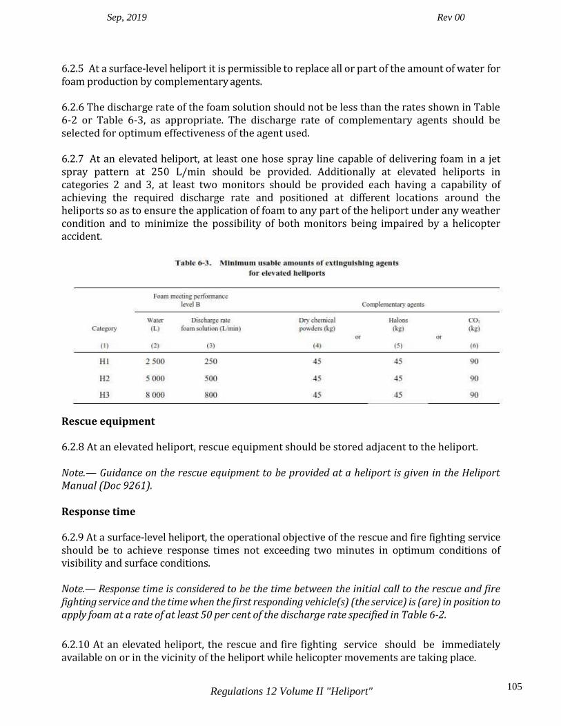
Sep, 2019 Rev 00
105 Regulations 12 Volume II "Heliport"
6.2.5 At a surface-level heliport it is permissible to replace all or part of the amount of water for foam production by complementary agents. 6.2.6 The discharge rate of the foam solution should not be less than the rates shown in Table 6-2 or Table 6-3, as appropriate. The discharge rate of complementary agents should be selected for optimum effectiveness of the agent used. 6.2.7 At an elevated heliport, at least one hose spray line capable of delivering foam in a jet spray pattern at 250 L/min should be provided. Additionally at elevated heliports in categories 2 and 3, at least two monitors should be provided each having a capability of achieving the required discharge rate and positioned at different locations around the heliports so as to ensure the application of foam to any part of the heliport under any weather condition and to minimize the possibility of both monitors being impaired by a helicopter accident.
Rescue equipment 6.2.8 At an elevated heliport, rescue equipment should be stored adjacent to the heliport. Note.— Guidance on the rescue equipment to be provided at a heliport is given in the Heliport Manual (Doc 9261). Response time 6.2.9 At a surface-level heliport, the operational objective of the rescue and fire fighting service should be to achieve response times not exceeding two minutes in optimum conditions of visibility and surface conditions. Note.— Response time is considered to be the time between the initial call to the rescue and fire fighting service and the time when the first responding vehicle(s) (the service) is (are) in position to apply foam at a rate of at least 50 per cent of the discharge rate specified in Table 6-2.
6.2.10 At an elevated heliport, the rescue and fire fighting service should be immediately available on or in the vicinity of the heliport while helicopter movements are taking place.

Sep, 2019 Rev 00
106 Regulations 12 Volume II "Heliport"
APPENDIX 1. AERONAUTICAL DATA QUALITY REQUIREMENTS
Note 1.— See Annex 15, Appendix 8, for graphical illustrations of obstacle data collection surfaces and criteria used to identify obstacles in the defined areas. Note 2.— Implementation of Annex 15, provisions 10.1.4 and 10.1.6, concerning the availability, as of 12 November 2015, of obstacle data according to Area 2 and Area 3 specifications would be facilitated by appropriate advance planning for the collection and processing of such data.

Sep, 2019 Rev 00
107 Regulations 12 Volume II "Heliport"
Note 1.— See Annex 15, Appendix 8, for graphical illustrations of obstacle data collection surfaces and criteria used to identify obstacles in the defined areas. Note 2.— Implementation of Annex 15, provisions 10.1.4 and 10.1.6, concerning the availability, as of 12 November 2015, of obstacle data according to Area 2 and Area 3 specifications would be facilitated by appropriate advance planning for the collection and processing of such data.
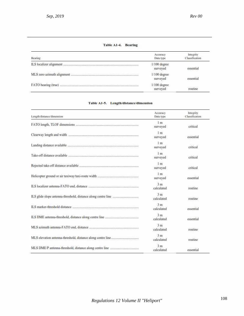
Sep, 2019 Rev 00
108 Regulations 12 Volume II "Heliport"
Sep, 2019 Rev 00
109 Regulations 12 Volume II "Heliport"
APPENDIX 2. INTERNATIONAL STANDARDS AND RECOMMENDED PRACTICES FOR INSTRUMENT HELIPORTS WITH NON-PRECISION AND/OR PRECISION APPROACHES AND INSTRUMENT DEPARTURES App 2-1 GENERAL Introductory Note 1.— ICAR 12 Volume II, contains Standards and Recommended Practices (specifications) that prescribe the physical characteristics and obstacle limitation surfaces to be provided for at heliports, and certain facilities and technical services normally provided at a heliport. It is not intended that these specifications limit or regulate the operation of an aircraft. Introductory Note 2.— The specifications in this appendix describe additional conditions beyond those found in the main sections of ICAR 12 Volume II, that apply to instrument heliports with non-precision and/or precision approaches. All specifications contained within the main chapters of ICAR 12 Volume II, are equally applicable to instrument heliports, but with reference to further provisions described in this Appendix.
App 2-2 HELIPORT DATA
App 2-5.1 Heliport elevation. The elevation of the TLOF and/or the elevation and geoid undulation of each threshold of the FATO (where appropriate) shall be measured and reported to the aeronautical information services authority to the accuracy of:
a. one-half metre or foot for non-precision approaches; and
b. one-quarter metre or foot for precision approaches. Note.— Geoid undulation must be measured in accordance with the appropriate system of coordinates. App 2-5.2 Heliport dimensions and related information The following additional data shall be measured or described, as appropriate, for each facility provided on an instrument heliport: a) distances to the nearest metre or foot of localizer and glide path elements comprising an instrument landing system (ILS) or azimuth and elevation antenna of a microwave landing system (MLS) in relation to the associated TLOF or FATO extremities.
App 2-3 PHYSICAL CHARACTERISTICS

Sep, 2019 Rev 00
110 Regulations 12 Volume II "Heliport"
App 2-3.1 Surface-level and elevate heliports Safety areas.
A safety area surrounding an instrument FATO shall extend:
a. laterally to a distance of at least 45 m on each side of the centre line; and
b. longitudinally to a distance of at least 60 m beyond the ends of the FATO. Note.— See Figure A2-1.
App 2-4 OBSTACLE ENVIRONMENT
App 2-4.1 Obstacle limitation surfaces and
sectors Approach surface
Characteristics. The limits of an approach surface shall comprise:
a) an inner edge horizontal and equal in length to the minimum specified width of the FATO plus the safety area, perpendicular to the centre line of the approach surface and located at the outer edge of the safety area;
b) two side edges originating at the ends of the inner edge;
i. for an instrument FATO with a non-precision approach, diverging uniformly at a
specified rate from the vertical plane containing the centre line of the FATO;
ii. for an instrument FATO with a precision approach, diverging uniformly at a specified rate from the vertical plane containing the centre line of the FATO, to a specified height above FATO, and then diverging uniformly at a specified rate to a specified final width and continuing thereafter at that width for the remaining length of the approach surface; and
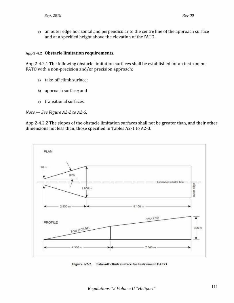
Sep, 2019 Rev 00
111 Regulations 12 Volume II "Heliport"
c) an outer edge horizontal and perpendicular to the centre line of the approach surface and at a specified height above the elevation of the FATO.
App 2-4.2 Obstacle limitation requirements. App 2-4.2.1 The following obstacle limitation surfaces shall be established for an instrument FATO with a non-precision and/or precision approach:
a) take-off climb surface;
b) approach surface; and
c) transitional surfaces. Note.— See Figure A2-2 to A2-5. App 2-4.2.2 The slopes of the obstacle limitation surfaces shall not be greater than, and their other dimensions not less than, those specified in Tables A2-1 to A2-3.
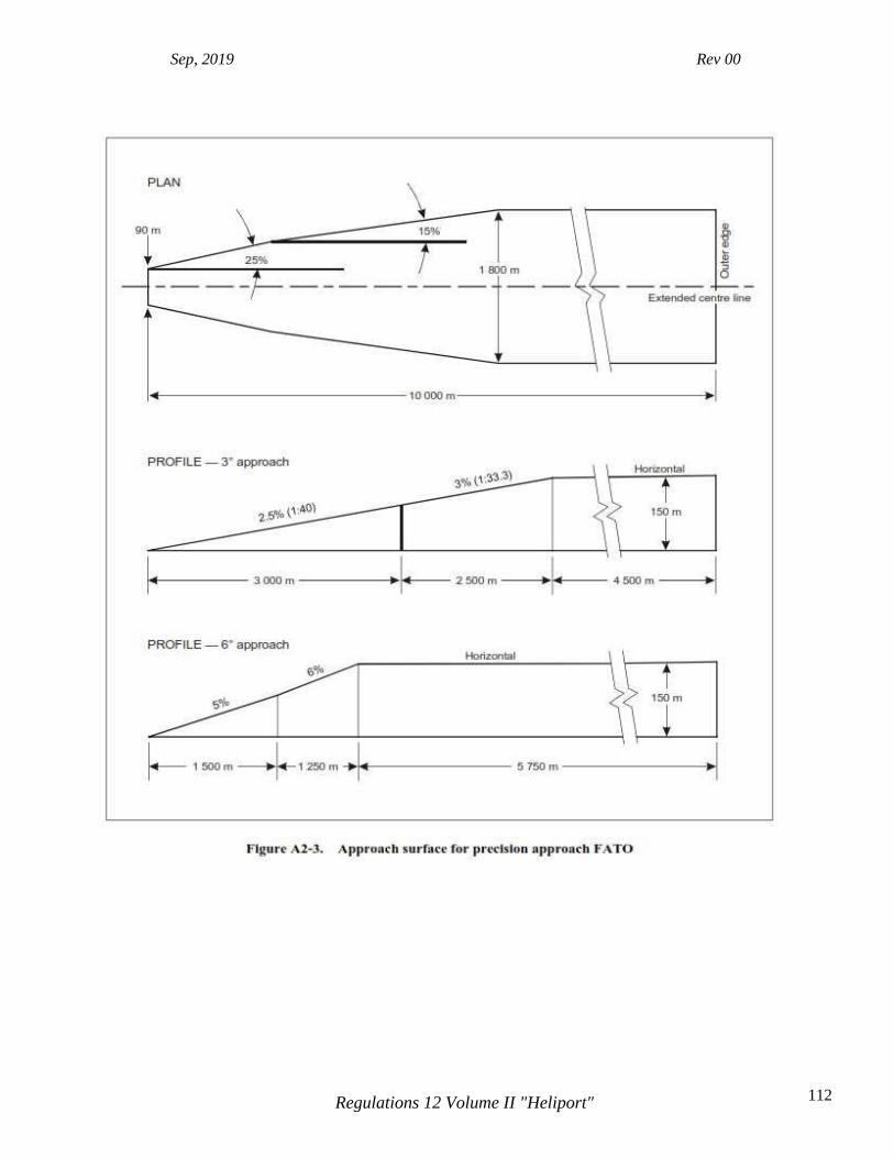
Sep, 2019 Rev 00
112 Regulations 12 Volume II "Heliport"
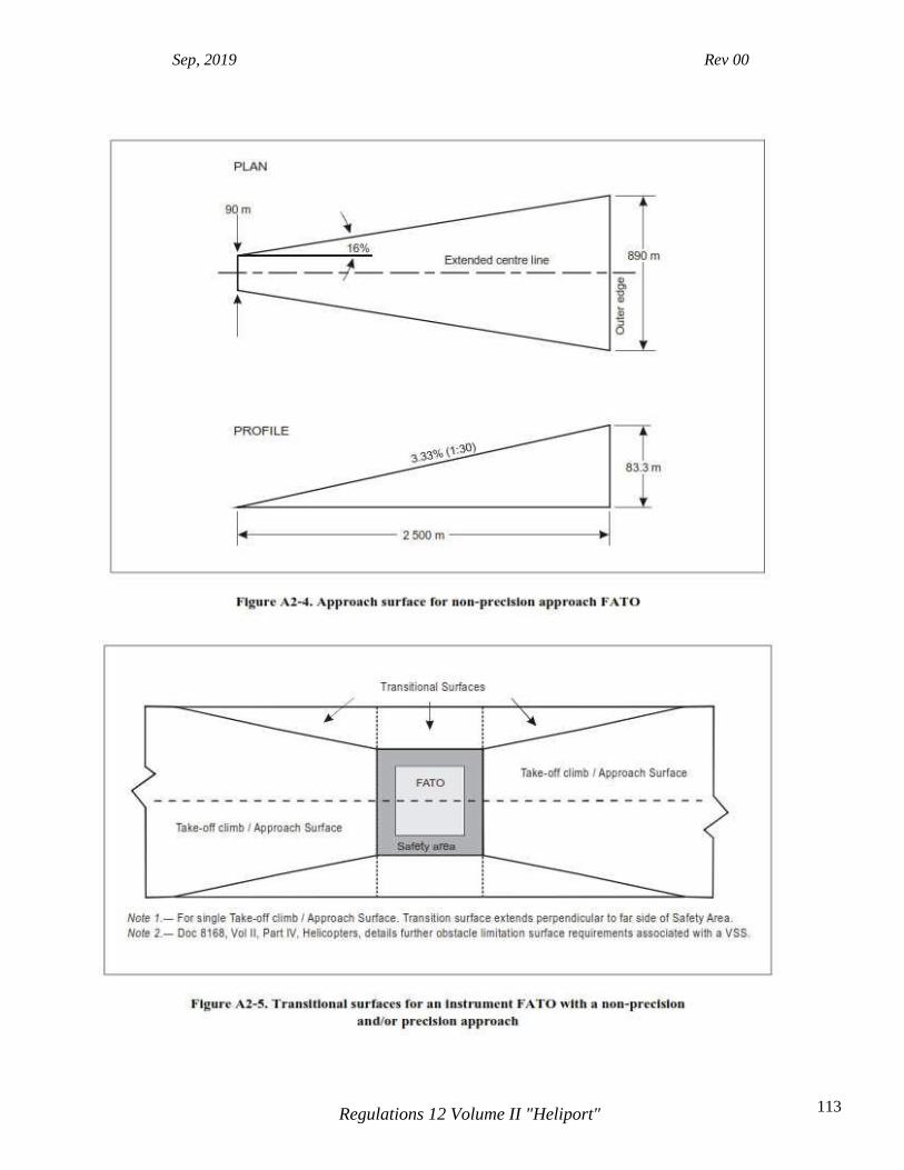
Sep, 2019 Rev 00
113 Regulations 12 Volume II "Heliport"
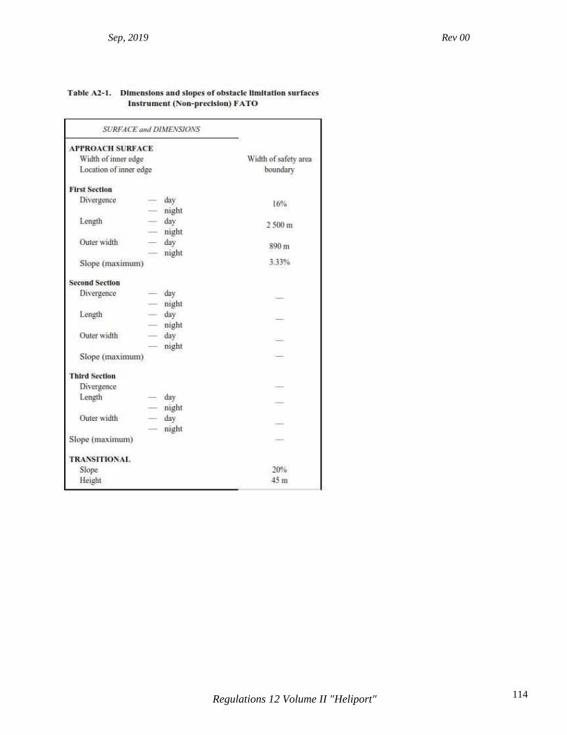
Sep, 2019 Rev 00
114 Regulations 12 Volume II "Heliport"

Sep, 2019 Rev 00
115 Regulations 12 Volume II "Heliport"

Sep, 2019 Rev 00
116 Regulations 12 Volume II "Heliport"

Sep, 2019 Rev 00
117 Regulations 12 Volume II "Heliport"
App 2-5 VISUAL AIDS
App 2-5.1 Lights Approach
Lighting Systems App 2-5.1.1 Where an approach lighting system is provided for a non-precision FATO, the system should not be less than 210 m in length. App 2-5.1.2 The light distribution of steady lights should be as indicated in Figure 5-11, Illustration 2 except that the intensity should be increased by a factor of three for a non-precision FATO.