Embed Size (px)
Citation preview

Page 1
Durability of Reinforced Concrete
By Chris Shaw CEng FICE FIET MIStructE MCMI Consultant, and Chairman, British Standard 7973 committee
Introduction. Reinforced concrete is the most widely used structural material worldwide. However, its ability to perform as designed is dependent on it being properly constructed. As a result of the CARES system it is very rare for there to be quality problems with the steel reinforcement in the UK. Most of the concrete itself now comes from quality assured ready mixed concrete suppliers, and quality problems are rare. The biggest problem with the use of reinforced concrete is the failure to position the reinforcement with the correct cover of concrete, and the durability suffers as a result. An example is shown in Figure 1. In 1999 the Building Research Establishment estimated that this type of failure costs £550 million each year in the UK alone, (more than £1.5million a day), and it is a worldwide problem. This Paper examines the problem, and covers the inspection of existing structures, and the requirements for the design of new ones. It focuses on the achievement of the cover because this is the area of greatest risk to the durability of reinforced concrete. It is essential to the durability of reinforced concrete structures that the specified cover to the reinforcement is achieved. For many years there was no published national guidance in the UK on how to achieve the specified cover correctly first time, every time. It was often left to the contractor to achieve the specified cover, or not as was frequently the case. The positioning of the steel reinforcement, either bar or welded fabric, is crucial in achieving the design performance of the structure.
Figure 1. Example of corroded reinforcement resulting from the failure to achieve the specified cover.
Background. The type and location of the spacers and chairs used to position the steel reinforcement are important for three reasons:-

Durability of Reinforced Concrete By Chris Shaw CEng FICE FIET MIStructE MCMI
Page 2
1. Structural If the reinforcement is not in the position where it was designed to be, the strength (and
safety) of the structure can be seriously affected. This is crucially important for cantilevers where the reinforcement is designed to be near the top of the concrete, but sometimes ends up in the middle or at the bottom due to inadequate support before or during concreting. Collapses can occur as a result.
2. Durability When the specified cover is not achieved the durability of the reinforced concrete is greatly reduced. The steel reinforcement starts to corrode, spalling off the face of the concrete and weakening the structure. As an example, for external concrete sheltered from the rain 30mm of cover will give 135 years of protection to the reinforcement, but 10mm of cover will give only 10 years of life. In marine locations any deficiency in the specified cover can greatly reduce the life of the structure in this demanding environment.
3. Fire In a fire the time before the heat reaches the reinforcement is dependent on the cover. When the reinforcement heats up, the steel softens and can no longer take the stresses for which it was designed. The structure can collapse, possibly with the firefighters and / or the occupants still inside a building.
Currently some buildings do not achieve their intended design lives due to deficiencies in the cover achieved. Some have had to be demolished prematurely, or have undergone extensive repairs, both of which can adversely affect their value. A key part of sustainable construction is the prudent use of resources. Structures can be built with the specified cover achieved, and this will ensure that they achieve their design life and do not fail prematurely from this cause. Examples of the lack of cover or misplaced reinforcement include spalling of the concrete face, wall reinforcement with too little or too much cover, reinforcement outside the concrete itself („negative cover‟), cantilever reinforcement in the bottom of a slab, and reinforcement laid on the ground with no cover to the bottom of the slab. These are only a small selection of the problems that continue to be found, even on current projects. There is another reason why this is important. Many buildings such as offices, warehouses etc. are used by pension funds, building societies and banks as investments. The value of the investment and the income from it is based on the building being properly constructed for its purpose. If the specified cover has not been achieved then the building may fail prematurely, the investment value is greatly reduced, and the income can be lost. Sometimes the building has to be demolished so the investment becomes worthless, and possibly a liability. The consequential losses in such cases are sometimes far more than the original building costs. When something goes wrong with a building the owners look for someone to blame. This can be the designer, the contractor, or both. In the UK, clients and their designers have a direct responsibility under the Construction (Design and Management), {CDM}, Regulations and Health & Safety legislation for the design, construction, maintenance and demolition of a building or structure. Designers also have a duty of care, a duty to use Standards and Codes of Practice where they exist, and to comply with their respective Institution‟s Code of Professional Conduct. Not achieving the specified cover can lead to spalling of the concrete, and pieces falling to the ground with possible injuries to people underneath. If the reinforcement is not in the correct position demolition contractors could face unnecessary hazards as they would have no way of knowing that the strength or behaviour of a structure during demolition was not what they would have expected from the design drawings. The correct use of spacers and chairs reduces the potential liability of this aspect of the construction.

Durability of Reinforced Concrete By Chris Shaw CEng FICE FIET MIStructE MCMI
Page 3
Inspecting existing buildings. Before 1989 there was no published national guidance on how to achieve the specified cover. Reinforcement was positioned using site made mortar blocks, pieces of brick, tile, wood, or other materials, if anything at all. Some published literature suggested placing the reinforcement into the wet concrete after it had been poured. It is therefore very likely that reinforced concrete in buildings built before 1989 will not have the specified cover to the reinforcement. They should be carefully inspected for signs of spalling, cracking, and / or excessive deflection. Checking with a cover meter can determine the actual cover achieved, although in areas of congested reinforcement this can be difficult. Radiography can also be used to „see‟ the position of the reinforcement (and other defects) in the concrete. Physical investigation by drilling and measuring is a useful but semi-destructive method of locating the reinforcement. For buildings built between 1989 and 2001 the question “Was the reinforcement positioned in accordance with Concrete Society report CS101?” should be asked. Usually there will be no response, often because the construction records are no longer available. In the absence of a positive confirmation it may be presumed that the building was not constructed in accordance with the requirements of CS101. If a positive reply is received then the question “What specific spacers and chairs were used?” should be asked. In the absence of a positive reply caution should be exercised. If a positive reply is received then the details should be checked to determine whether the products used were compliant with the requirements of, and used in accordance with, CS101. Site record photographs are useful for this. Often, inferior products were used. For buildings built from 2001 onwards the question “Was the reinforcement positioned in accordance with the requirements of British Standard 7973 „Spacers and chairs for steel reinforcement and their specification‟?” should be asked. The Standard was published in 2001 and is the result of over 30 years of research, development, and application of the requirements in actual structures. Usually there will be no response to the question, sometimes because the construction records are no longer available. In the absence of a positive confirmation it may be presumed that the building was not constructed in accordance with the requirements of BS 7973. If a positive reply is received then the question “What specific spacers and chairs were used?” should be asked. The recipient should be asked for details of the products used, their reference numbers, the manufacturer / supplier‟s details, and copies of the Specification, a typical reinforced concrete drawing, and / or record photographs of the work under construction. In the absence of a positive reply caution should be exercised. If a positive reply is received then the details should be checked to determine whether the products used were compliant with BS 7973 -1:2001, and used in accordance with BS 7973 -2:2001. Often, non-compliant products are used, and used incorrectly, even on current projects. The use of the questions reflects the importance of this aspect of the construction on the safety and value of the building. Additional questions relating to other aspects of the concrete work, such as the types of cement and aggregates used, may also need to be asked. Design of new buildings. Reinforced concrete, both in-situ and pre-cast, for new buildings should comply with British Standard 8110, (BS 8110), the „Structural Use of Concrete‟, at least until such time as it is replaced by Eurocode 2 and its National Annexe. BS 7973 is a freestanding Standard and will not be affected by the introduction of the Eurocode. Compliance with BS 8110 is often quoted in support an application under Part A of The Building Regulations. BS 7973 is incorporated by reference in Section 7.3 of BS 8110, so compliance with BS 8110 requires compliance with BS 7973 as well in order to be valid.

Durability of Reinforced Concrete By Chris Shaw CEng FICE FIET MIStructE MCMI
Page 4
However, it is possible to achieve the specified cover to the reinforcement, first time, every time, through the application of the requirements of British Standard 7973 “Spacers and chairs for steel reinforcement and their specification”. The Standard consists of two parts. Part 1 gives the requirements for the products i.e. the spacers and chairs, and Part 2 shows how they need to be used in order to achieve the specified cover. It is also necessary to inspect the reinforcement prior to concreting to ensure that the specified requirements have been met. Too often non-compliant products are used, and in a non-compliant manner. The process chain. So why does it go wrong? The construction process involves many people. Observation has shown that there are still many structures where reinforced concrete is being used but the specified cover is not being achieved. The participants of a study generally agreed that the defects could be roughly equally divided between operatives (53%) which included steel fixers, formwork fixers, and placing and compaction operatives; and management (47%) which included architects, consulting engineers, designers, contractor‟s management, reinforcement suppliers, and site engineers. The process chain is a long one and the omission can occur at any one or more of the stages for the following reasons:
The client is probably not aware of the problem, and assumes that their consultants will design and the contractor will build the structure in accordance with all of the Standards.
The project manager takes an overview of the project and does not usually get involved in the actual design.
The designer concentrates on the calculations, and passes these to the detailer who may be some distance away in another office, organisation or country.
Having not received instructions on the spacers and chairs to use the detailer does not include them on the reinforcement drawings.
The contractor‟s estimator does not see anything about spacers or chairs specified on the drawings or in the Specification, so does not include for them in the price for the work.
The contractor often sub-contracts the fixing of the steel reinforcement entirely to another contractor, who receives no instructions regarding the spacers and chairs from the drawings, Specification, or contractor. Research has shown that steel reinforcement sub-contracting fixing companies are sometimes not even aware of the requirements in the British Standards.
The end result is that all too often the reinforcement does not end up in the correct position, or in accordance with the Standards. This can be remedied by:-
The requirement to comply with BS 7973 being specifically written in to the Specification.
Including on the reinforced concrete drawings „The specified cover shall be achieved by the application of BS 7973 “Spacers and chairs for steel reinforcement and their specification”‟.
Raising awareness of the problem and the solution, throughout the process chain. This is becoming increasingly important for clients with the current revisions to the CDM Regulations.
Some designers and contractors are known to be using this approach, and benefiting from the commercial advantage that results from its use. Consultants and designers specifying and using the Standard have reduced their potential liability for Professional Indemnity Insurance (PII) claims being made against them. Such claims, successful or otherwise, are inevitably costly and best avoided whenever possible. Contractors using the Standard benefit from getting the work right first time every time. They do not then need to become involved in disputes regarding the actual cover achieved, costly remedial works and delays whilst the matter is sorted out, or, in the worst case, demolition and rebuilding of the affected work.

Durability of Reinforced Concrete By Chris Shaw CEng FICE FIET MIStructE MCMI
Page 5
Development of the British Standard. The publication of British Standard 7973 in October 2001 was a landmark towards achieving the specified cover. It was the result of many years of research into the problem and the development of measures to overcome it. The author‟s recognition of the problem started in 1968 and by 1979 a system had been devised and tested on actual construction projects for the first time. The first comprehensive nationally published guidance was the Concrete Society Report CS101 in 1989. Other publications followed and it was then decided that this proven system warranted its own British Standard which was published as BS 7973 in 2001. A Paper on cover was presented at the 6th International Congress on Concrete in Dundee in 2005 and the author is now recognised worldwide as the leading authority on this subject. The products. Spacers provide the specified cover between the reinforcement nearest to the surface of the concrete and the surface itself. The surface may be horizontal (e.g. slabs), vertical (e.g. walls), or inclined. Chairs are used to support the top (usually horizontal) reinforcement from the bottom reinforcement or to separate layers of vertical reinforcement in walls. Historically, spacers and chairs have been the poor relation of the concrete industry. Pieces of wood, brick, broken concrete, tile and slate have all been seen used as spacers, even on recent projects. At one time site made sand / cement blocks with pieces of tying wire cast in them were a preferred option. Factory made spacers have now replaced site made ones, which are excluded in British Standard 8110-1 the “Structural Use of Concrete”. BS 7973 contains the performance requirements for both plastic and cementitious spacers, and steel wire chairs. These have been developed to carry the normal construction loads associated with their particular applications. The selection of the relevant category partly depends on the size of the reinforcement to which they are to be fixed. Although spacers and chairs complying with BS 7973 are available there are also many non-compliant products on the market. Spacer and chair types. There are three types of spacers and chairs included in the Standard. 1. Plastics spacers. 2. Cementitious spacers 3. Wire chairs. Each has its correct use. Most buildings and structures can be built using a total of about four types of spacer and chair. Many of the designs of spacer and chair currently on the market do not comply with the requirements of the Standard, and have been observed to fail in practice in various ways. Spacers manufactured to provide a single cover value should always be used. Spacers with more than one cover value are often placed with the incorrect cover. For example, triple cover cementitious spacers have been found placed in any one of four cover positions, so there is only a 25% likelihood that the correct cover position will be used. These spacers are also prone to fracture under load. Spacer and chair categories and applications.

Durability of Reinforced Concrete By Chris Shaw CEng FICE FIET MIStructE MCMI
Page 6
Three categories of spacers and one of chairs are included in the Standard, and the applications are specified in Table 1 of BS 7973 -1. The categories for spacers are light, normal and heavy. Light category Light category spacers provide the cover in vertical members to the reinforcement nearest to the surface of the concrete, or to horizontal reinforcement in small sections not subject to foot traffic, e.g. pre-cast concrete products. They are used on reinforcement up and including 16mm in size. Normal category Normal category spacers are used for most in-situ concrete work and can be used for larger pre-cast products. They provide the cover where the size of the reinforcement to which they are fixed is 20mm or less. Heavy category Heavy category spacers provide the cover where the size of the reinforcement is greater than 20mm. This is typically in bridge decks and heavily reinforced foundations. Chairs Chairs are used to support the top reinforcement from the bottom reinforcement in slabs to provide the required top cover. They are also used to separate layers of reinforcement e.g. between the reinforcement in opposite faces of a wall. They are manufactured as continuous, individual, or circular. Continuous chairs are widely used for separating layers of reinforcement. Individual chairs with protective tips can be used to support the top reinforcement in slabs where there is no bottom reinforcement provided e.g. cantilevers. Plastic spacers. Single cover „A‟ spacer
This is a plastic „A‟ spacer. It is „state of the art‟ in plastic spacers, and the result of many years of development and use on actual projects. It is used for most purposes in building including foundations, columns, beams, slabs, and walls. It is designed for use with conventional formwork and 8mm up to 20mm size reinforcement. The spacer clips on to the reinforcement and overall is the most cost effective option because it does not need tying on with wire. The labour used in tying is expensive. It is manufactured for covers of 20, 25, 30, 40, 50, and 90mm.
Soft substrate „A‟ spacer
Where a plastic „A‟ spacer has to rest on a soft substrate (i.e. not on conventional formwork) such as thermal insulation a spreader base is used. This clips to the base of the „A‟ spacer and spreads the load carried by the spacer into the insulation. The spreader base can also be used in vertical applications such as basement walls where, for example, a reinforced concrete wall is cast against a waterproof membrane, such as „Sheetseal‟ or „Bituthene‟.
End Spacers

Durability of Reinforced Concrete By Chris Shaw CEng FICE FIET MIStructE MCMI
Page 7
End spacers are used at the ends of the wires of welded steel fabric and reinforcing bars to ensure the correct end cover. The left hand one shown in the picture is for the wires of the smaller sizes of welded steel fabric. The right hand one is for the wires of larger size welded steel fabric and for the smaller sizes of reinforcing bars. End spacers for the larger sizes of reinforcing bar are not currently available. In this situation the ends of the bars need to be bent through 90o and an „A‟ spacer fixed to the short straight section at the end of the bar. End spacers also act as an „anti-hazard‟ device until the concrete is poured.
Circular Spacers
Circular (or „wheel‟) spacers have been used in the past, mainly on vertical concrete members such as walls and columns. However, they contain more plastic than is necessary for a single cover spacer and are therefore not a good use of resources. The „A‟ spacer provides the same cover more efficiently, so circular spacers are normally no longer needed.
Pile Cage Former for CFA and Bored Piles
The pile cage former is used for continuous flight auger (CFA) and bored piles. It combines the functions of the spacer with two plastic rings to position the longitudinal reinforcement for the pile. The rings have pre-formed scallop shaped recesses on the inside edge for locating the main reinforcement, which can be up to 25mm in size. The cover to the reinforcement provided by the spacers and rings is 50, 75 or 100mm. The spacer is used for piles from 250mm to 525mm in diameter.
Cementitious spacers. Single cover cementitious spacer
Cementitious spacers, such as the one shown on the left, are used where the surface of the concrete may be subject to abrasion, e.g. in the seaward side of a sea wall. They require to be wired on to the reinforcement. The wire is traditionally 16 or 18 gauge soft iron wire but in marine environments stainless steel tying wire should be used. They are also used to provide cover to reinforcement of 25mm size and above. This would include the end cover to the reinforcement at the edge of a slab or beam which should be bent at 90o to its longitudinal axis. Spacers made on site are not permitted in the Standard.
Cementitious line spacer
Durability of Reinforced Concrete By Chris Shaw CEng FICE FIET MIStructE MCMI
Page 8
The spacer shown on the left is a cementitious line spacer. It is used to support reinforcement of 25mm size and above. It is mainly used for bridge decks and heavily reinforced foundations. They are manufactured in 1m lengths and in sizes from 25mm up to 60mm. They should be used in short lengths not exceeding about 350mm, and the lengths should be staggered in plan on the formwork as shown in Figure 1(a) of BS 7973 -2:2001.
Wire chairs. Lattice type continuous wire chair
There are two types of continuous wire chairs. One type is the lattice chair as shown on the left. The other type, the goalpost, is shown below. The Standard requires this type of continuous chair to be manufactured from three longitudinal steel or stainless steel wires of the same size in order to carry the design load. In practice, for a lattice support wire spacing of 200mm the top wire needs to be of 5mm size. Beware of non-compliant chairs with wires of a significantly lesser size. The chairs are manufactured in heights from 50mm to 200mm. Greater heights are also available upon request to the manufacturers.
Goalpost type continuous wire chair
On the left is shown a goalpost type continuous wire chair. The Standard requires this type of continuous chair to be manufactured from three longitudinal steel or stainless steel wires of the same size in order to carry the design load. In practice, for a goalpost support wire spacing of 100mm the top wire needs to be of 3.5mm size. Beware of non-compliant chairs with wires of a significantly lesser size. The chairs are manufactured in heights from 30mm to 200mm (standard duty) and up to 400mm (heavy duty). Greater heights, and tapering chairs, are also available upon request to the manufacturers.
Individual wire chair
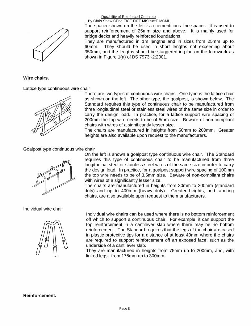
Individual wire chairs can be used where there is no bottom reinforcement off which to support a continuous chair. For example, it can support the top reinforcement in a cantilever slab where there may be no bottom reinforcement. The Standard requires that the legs of the chair are cased in plastic protective tips for a distance of at least 40mm where the chairs are required to support reinforcement off an exposed face, such as the underside of a cantilever slab. They are manufactured in heights from 75mm up to 200mm, and, with linked legs, from 175mm up to 300mm.
Reinforcement.

Durability of Reinforced Concrete By Chris Shaw CEng FICE FIET MIStructE MCMI
Page 9
The detailing of the reinforcement is particularly important and the Standard Method of Detailing Structural Concrete, (Third Edition), published by The Institution of Structural Engineers, 11 Upper Belgrave Street, London, SW1X 8BH should be used. Tel: 020 7235 4535. ISBN 0 901297 41 0. Flexible detailing of reinforcement should always be used, and single bars extending the full length between fixed faces of the concrete should be avoided because this can reduce the specified cover significantly. In addition, reinforcement at right angles to the edge of a slab should be fixed by locating the bar with the specified end cover and tying it from that end inward. Tolerances in the formwork dimensions can also reduce the cover, but „flexibly‟ detailed reinforcement can overcome this problem. Correct detailing and tying of the reinforcement, together with the selection and use of the correct spacers and chairs can ensure that that the specified cover is achieved. When scheduling reinforcement such as links (shape code 51 in BS 8666:2005) in beams and columns an additional 5mm should be deducted from dimensions A and B to allow for tolerances in the reinforcement and formwork and reduce the possibility of the specified cover not being achieved. Reinforcing bars wired together and welded steel fabric to BS 4483 behave differently when subject to construction loads. Welded steel fabric reinforcement to BS 4483 is produced in four ranges of preferred types; A, B, C, and D. BS 7973 is applicable to types A393 to A142, B1131 to B283, and C785 to C385. Fabric types A98, B196, C283, D49 and D98 are not suitable for supporting foot traffic. Tying of reinforcement. Reinforcement needs to be tied together to prevent displacement of the bars before or during concreting. Sheets of welded steel fabric may also require tying together. The spacing of ties for slabs, beams, columns foundations and walls is given in BS 7973 -2. Slash ties are recommended for tying the reinforcement in slabs; ring slash and crown ties in walls; and crown or hairpin ties in beams and columns. The tying forms an integral part of the system to achieve the correct positioning of the reinforcement. The Standard contains requirements for the tying and the types of ties shown in Figure 2 should be specified and used for the correct application.
Note: The ends of the tying wire should not encroach into the concrete cover.
Figure 2. Six types of ties.
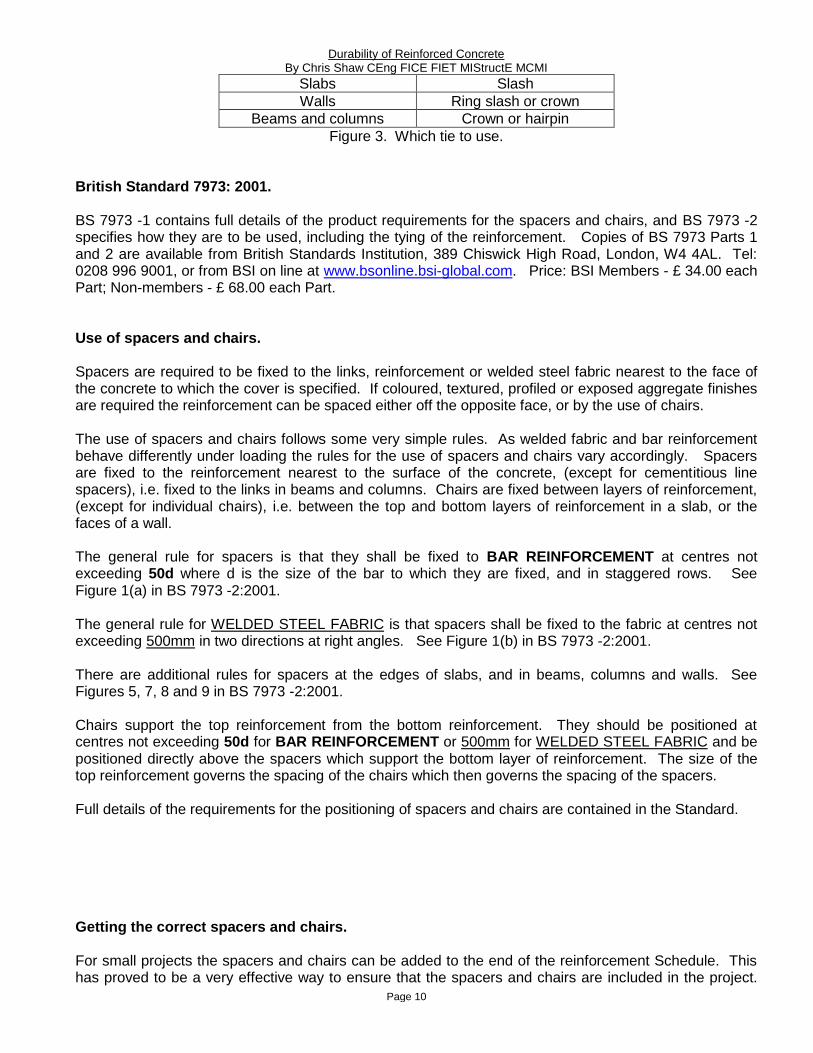
The ties are used for different applications in concrete members as shown in Figure 3.
MEMBER TYPE OF TIE TO BE USED
Durability of Reinforced Concrete By Chris Shaw CEng FICE FIET MIStructE MCMI
Page 10
Slabs Slash
Walls Ring slash or crown
Beams and columns Crown or hairpin
Figure 3. Which tie to use.
British Standard 7973: 2001. BS 7973 -1 contains full details of the product requirements for the spacers and chairs, and BS 7973 -2 specifies how they are to be used, including the tying of the reinforcement. Copies of BS 7973 Parts 1 and 2 are available from British Standards Institution, 389 Chiswick High Road, London, W4 4AL. Tel: 0208 996 9001, or from BSI on line at www.bsonline.bsi-global.com. Price: BSI Members - £ 34.00 each Part; Non-members - £ 68.00 each Part. Use of spacers and chairs. Spacers are required to be fixed to the links, reinforcement or welded steel fabric nearest to the face of the concrete to which the cover is specified. If coloured, textured, profiled or exposed aggregate finishes are required the reinforcement can be spaced either off the opposite face, or by the use of chairs. The use of spacers and chairs follows some very simple rules. As welded fabric and bar reinforcement behave differently under loading the rules for the use of spacers and chairs vary accordingly. Spacers are fixed to the reinforcement nearest to the surface of the concrete, (except for cementitious line spacers), i.e. fixed to the links in beams and columns. Chairs are fixed between layers of reinforcement, (except for individual chairs), i.e. between the top and bottom layers of reinforcement in a slab, or the faces of a wall. The general rule for spacers is that they shall be fixed to BAR REINFORCEMENT at centres not exceeding 50d where d is the size of the bar to which they are fixed, and in staggered rows. See Figure 1(a) in BS 7973 -2:2001. The general rule for WELDED STEEL FABRIC is that spacers shall be fixed to the fabric at centres not exceeding 500mm in two directions at right angles. See Figure 1(b) in BS 7973 -2:2001. There are additional rules for spacers at the edges of slabs, and in beams, columns and walls. See Figures 5, 7, 8 and 9 in BS 7973 -2:2001. Chairs support the top reinforcement from the bottom reinforcement. They should be positioned at centres not exceeding 50d for BAR REINFORCEMENT or 500mm for WELDED STEEL FABRIC and be positioned directly above the spacers which support the bottom layer of reinforcement. The size of the top reinforcement governs the spacing of the chairs which then governs the spacing of the spacers. Full details of the requirements for the positioning of spacers and chairs are contained in the Standard. Getting the correct spacers and chairs. For small projects the spacers and chairs can be added to the end of the reinforcement Schedule. This has proved to be a very effective way to ensure that the spacers and chairs are included in the project.

Durability of Reinforced Concrete By Chris Shaw CEng FICE FIET MIStructE MCMI
Page 11
An example is attached as Appendix A to this Paper. The inclusion of the quantity of spacers in addition to the specification of the types is optional, but has been found to greatly assist builders working on smaller projects. For larger projects it is also possible to produce a Schedule of the spacers and chairs required for the various elements of the structure, or to add the requirements into the Notes on the drawing. For example:-
For beams; 25mm cover to bottom, sides and top; AN 1290 „A‟ spacers to BS 7973 –2:2001.
For ground slabs with insulation below them; 40mm bottom cover; AN 1296 „A‟ spacers to BS 7973 -2
:2001 with B1394 bases.
For suspended slabs with top and bottom reinforcement; 25mm bottom cover; AN 1290 „A‟ spacers to BS 7973 -2:2001,and 100mm high continuous wire chairs to BS 7973 -2:2001.
Figure 4. Spacers being fixed in accordance with BS 7973.
Using BS 7973. The provisions in the Standard have been developed over more than 30 years and used in actual structures for more than 25 years. The application of the requirements of BS 7973 is the cheapest and most sustainable way to ensure that the design life of the specified cover is achieved. Their use will ensure that the specified cover to the reinforcement will be achieved first time, every time. The provisions of BS 7973 have world-wide applications wherever reinforced concrete is used. The requirements of BS 7973 can easily be implemented by:-

Durability of Reinforced Concrete By Chris Shaw CEng FICE FIET MIStructE MCMI
Page 12
In the Specification add the text “Spacers and chairs shall comply with the requirements of British
Standard 7973 -1: 2001, and be fixed in accordance with BS 7973 -2: 2001”. On each reinforced concrete drawing include the text “Spacers and chairs shall comply with the
requirements of British Standard 7973 -1: 2001, and be fixed in accordance with BS 7973 -2: 2001, in particular Figures 1 to 9”.
Select the correct type of spacers and chairs for the reinforcement and the intended use at the design stage.
Either show the spacers and chairs on the drawings (for small projects) or use standard drawings based on the Figures in BS 7973 -2: 2001 (for larger projects), or specific reference can be made to the Figures in BS 7973 -2: 2001. For example, “Spacers for beams shall be positioned in accordance with Figure 7 of BS 7973 -2: 2001”. Similar text can be used for columns, slabs and walls.
Check that the spacers and chairs that are supplied are as specified and in accordance with the requirements of BS 7973 -1:2001. Be aware that there are many non-compliant products on the market. A site visit is the best way to check this. Where a visit is not possible a risk assessment base approach is much better than nothing at all. The following requirements can be incorporated into the Specification so that the contractor is aware of them at the time of tender.
Whether or not you will be able to inspect the reinforcement on site before concreting check:-
Before construction starts: Ask the contractor to confirm in writing the specific spacers and chairs
that he proposes to use. Ask for the manufacturer(s) details and the product reference numbers. Check what is proposed from the manufacturer(s) catalogues; and;
During construction: Ask the contractor for a sample of each of the spacer and chair types that he is using to be delivered to your office. Check what is sent. Ask for digital photographs of the reinforcement, spacers and chairs before concreting. These can be sent by email.
If the concrete has already been poured: After concreting: Ask the contractor for samples of the spacers and chairs that were used and / or
copies of the delivery notes / purchase receipts for the spacers and chairs. There are usually some samlpes left over after concreting. Look at record photographs of the work.
Summary. The publication of BS 7973 is a major step forward to the achievement of the specified cover to the reinforcement in reinforced concrete structures. The provisions of BS 7973 have world-wide applications wherever reinforced concrete is used. It enables the specified cover to be achieved first time, every time. It is the cheapest and most sustainable way to ensure that the cover is achieved. This will ensure that the structural, durability and fire performance of buildings in respect of the cover to the reinforcement.
-oOo- Worked examples of spacers and chairs for the design of new work. 1) Beam.

Durability of Reinforced Concrete By Chris Shaw CEng FICE FIET MIStructE MCMI
Page 13
Consider a beam 500mm deep by 300mm wide. This is a „Normal‟ beam to BS 7973 – 2, Figure 7(c). It has 30mm cover to the sides and soffit. The main reinforcement is 25mm size and the links are 12mm size at 200mm centres. The spacers required would be „A‟ spacers, reference AN1292 in groups of four, fixed to the LINKS in the positions shown in BS 7973 –2, Figure 7(c). The spacing of the groups along the links would be at centres not exceeding 1000mm, (see BS 7973 –2, Figure 7(a)); therefore not exceeding every fifth link as the links are at 200mm centres along the beam. 2) Column. Consider a 400mm square column 4.5m high. This is a „Small‟ column to BS 7973 –2, Figure 8(b). It has 30mm cover to the links. The main reinforcement is 25mm size and the links are 12mm size at 200mm centres. The spacers would be „A‟ spacers, reference AN1292 in groups of six, arranged as shown in BS 7973 –2, Figure 8(b). The spacing of the groups of spacers up the height of the column is governed by the size of the MAIN reinforcement. The groups of spacers should be located at the top, middle and bottom of the column and at centres up the column not exceeding 100 D where D is the size of the MAIN reinforcement. In this case the centres up the column would be 100 x 25 = 2500mm which means that groups of spacers fixed to the LINKS at the top, middle and bottom of the column are sufficient to comply with the Standard. This is usually the case for most columns. 3) Wall. Consider a wall 250mm thick with 25mm cover to the reinforcement on each face. The reinforcement is A393 standard welded steel fabric comprising 10mm wires at 200m centres in each direction, with the outer wires being vertical on each face of the wall. The size of the chairs to be fixed between the welded steel fabric would therefore be 250 – (2 x 25) – (4 x 10) = 160mm. Therefore for vertical continuous chairs 150mm high ones would be selected. Chairs can be used horizontally along the length of a wall positioned between the OUTER layers of reinforcement. In this case the chairs would be 250 – (2 x 25) – (2 x 10) = 180mm, which is exactly a standard size. Therefore the designer has a choice of using 150mm high chairs used vertically or 180mm high chairs used horizontally. The preferred choice is to use the chairs vertically because this assists the placing of the concrete in the wall. The 10mm difference between the 160mm calculated size and the 150mm manufactured size gives 10mm of tolerance and ensures that the 25mm cover can be achieved for both faces of the wall. The spacers would be 25mm „A‟ spacers, reference AN 1290, fixed at 400mm centres horizontally (i.e. every other vertical wire) and at centres not exceeding 500mm vertically up the wires. The spacers and chairs should line up when viewed in elevation as shown in BS 7973 –2, Figure 9. 4) Suspended slab with top and bottom reinforcement – Example 1. Slabs can have either bottom or top reinforcement only or have both top and bottom reinforcement. Slabs with bottom reinforcement only are illustrated in BS 7973 –2, Figure 1, and slabs with top reinforcement only are illustrated in BS 7973 -2, Figure 3. Slabs with both top and bottom reinforcement require both spacers and chairs. Consider a slab 250mm thick with 25mm cover to the reinforcement at the top and bottom faces. The reinforcement is 12mm size bar at 200mm centres each way in the bottom and 10mm size bar at 200mm centres each way in the top. The height of the chairs supporting the top reinforcement would be 250 – 25 – 25 - (2 x 12) – (2 x 10) = 156mm. Therefore use 150mm high continuous lattice or goalpost type chairs at centres not exceeding 50 x 10 = 500mm, in parallel rows. The spacers would be 25mm „A‟ spacers, reference AN1290, at centres not exceeding 50 x 12 = 600 mm along the bars. Across the bars the 600mm centres would need to be reduced to match the centres of the chairs i.e. 500mm, but the reinforcement is at 200mm centres so the spacers would need to be fixed
Durability of Reinforced Concrete By Chris Shaw CEng FICE FIET MIStructE MCMI
Page 14
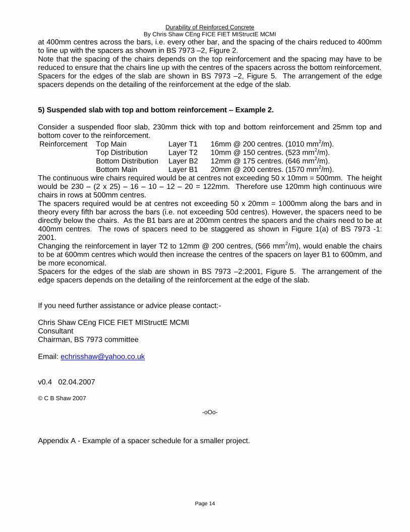
at 400mm centres across the bars, i.e. every other bar, and the spacing of the chairs reduced to 400mm to line up with the spacers as shown in BS 7973 –2, Figure 2. Note that the spacing of the chairs depends on the top reinforcement and the spacing may have to be reduced to ensure that the chairs line up with the centres of the spacers across the bottom reinforcement. Spacers for the edges of the slab are shown in BS 7973 –2, Figure 5. The arrangement of the edge spacers depends on the detailing of the reinforcement at the edge of the slab. 5) Suspended slab with top and bottom reinforcement – Example 2. Consider a suspended floor slab, 230mm thick with top and bottom reinforcement and 25mm top and bottom cover to the reinforcement. Reinforcement Top Main Layer T1 16mm @ 200 centres. (1010 mm2/m).
Top Distribution Layer T2 10mm @ 150 centres. (523 mm2/m). Bottom Distribution Layer B2 12mm @ 175 centres. (646 mm2/m). Bottom Main Layer B1 20mm @ 200 centres. (1570 mm2/m).
The continuous wire chairs required would be at centres not exceeding 50 x 10mm = 500mm. The height would be 230 – (2 x 25) – 16 – 10 – 12 – 20 = 122mm. Therefore use 120mm high continuous wire chairs in rows at 500mm centres. The spacers required would be at centres not exceeding 50 x 20mm = 1000mm along the bars and in theory every fifth bar across the bars (i.e. not exceeding 50d centres). However, the spacers need to be directly below the chairs. As the B1 bars are at 200mm centres the spacers and the chairs need to be at 400mm centres. The rows of spacers need to be staggered as shown in Figure 1(a) of BS 7973 -1: 2001. Changing the reinforcement in layer T2 to 12mm @ 200 centres, (566 mm2/m), would enable the chairs to be at 600mm centres which would then increase the centres of the spacers on layer B1 to 600mm, and be more economical. Spacers for the edges of the slab are shown in BS 7973 –2:2001, Figure 5. The arrangement of the edge spacers depends on the detailing of the reinforcement at the edge of the slab. If you need further assistance or advice please contact:- Chris Shaw CEng FICE FIET MIStructE MCMI Consultant Chairman, BS 7973 committee Email: [email protected] v0.4 02.04.2007 © C B Shaw 2007
-oOo-
Appendix A - Example of a spacer schedule for a smaller project.

Durability of Reinforced Concrete By Chris Shaw CEng FICE FIET MIStructE MCMI
Page 15