Embed Size (px)
Citation preview
8/14/2019 Behavior and Design of Reinforced Concrete.pdf
http://slidepdf.com/reader/full/behavior-and-design-of-reinforced-concretepdf 1/27
Behavior and Design of Reinforced Concrete,
Steel, and Steel-Concrete Coupling Beams
Kent A. Harries1, M.EERI, Bingnian Gong2, and Bahram M. Shahrooz3
Corresponding (first) author: Kent A. Harries
Mailing address: USC-Civil Engineering, 300 Main Street, Columbia, SC 29208
Phone: 803 777 0671
Fax: 803 777 0670
E-mail address: [email protected]
Submission date for review copies: February 7, 2000
Submission date for camera-ready copy: June 21, 2000
(KAH) Dept. of Civil and Environmental Engineering, University of South Carolina, Columbia, SC 29208(BG) CBM Engineers, Inc., 1700 W. Loop So., Suite 830, Houston, TX 77027(BMS) Dept. of Civil and Environmental Engineering, University of Cincinnati, Cincinnati, OH 45221-0071
8/14/2019 Behavior and Design of Reinforced Concrete.pdf
http://slidepdf.com/reader/full/behavior-and-design-of-reinforced-concretepdf 2/27
Behavior and Design of Reinforced Concrete,
Steel, and Steel-Concrete Coupling Beams
Kent A. Harries4, M.EERI, Bingnian Gong5, and Bahram M. Shahrooz6
The efficiency of coupled wall systems to resist lateral loads is wellknown. In order for the desired behavior of the coupled wall system to be
attained, the coupling beams must be sufficiently strong and stiff. The
coupling beams, however, must also yield before the wall piers, behave in aductile manner, and exhibit significant energy absorbing characteristics. This
paper reviews the current state of the art for the design of conventional
reinforced concrete, diagonally reinforced concrete, steel and composite steel-concrete coupling beams. Although not exhaustive, critical aspects of the
design of these systems are presented.
INTRODUCTION
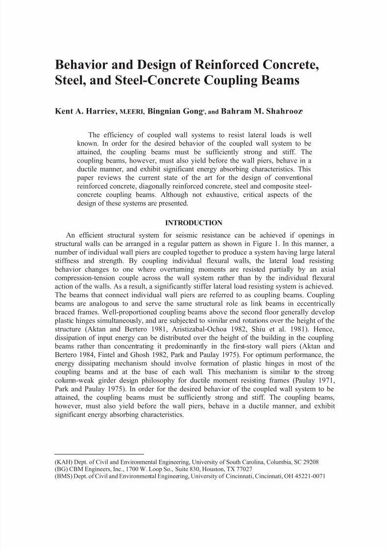
An efficient structural system for seismic resistance can be achieved if openings in
structural walls can be arranged in a regular pattern as shown in Figure 1. In this manner, a
number of individual wall piers are coupled together to produce a system having large lateralstiffness and strength. By coupling individual flexural walls, the lateral load resisting
behavior changes to one where overturning moments are resisted partially by an axial
compression-tension couple across the wall system rather than by the individual flexural
action of the walls. As a result, a significantly stiffer lateral load resisting system is achieved.The beams that connect individual wall piers are referred to as coupling beams. Coupling
beams are analogous to and serve the same structural role as link beams in eccentrically
braced frames. Well-proportioned coupling beams above the second floor generally develop plastic hinges simultaneously, and are subjected to similar end rotations over the height of the
structure (Aktan and Bertero 1981, Aristizabal-Ochoa 1982, Shiu et al. 1981). Hence,
dissipation of input energy can be distributed over the height of the building in the coupling beams rather than concentrating it predominantly in the first-story wall piers (Aktan and
Bertero 1984, Fintel and Ghosh 1982, Park and Paulay 1975). For optimum performance, the
energy dissipating mechanism should involve formation of plastic hinges in most of thecoupling beams and at the base of each wall. This mechanism is similar to the strong
column-weak girder design philosophy for ductile moment resisting frames (Paulay 1971,Park and Paulay 1975). In order for the desired behavior of the coupled wall system to beattained, the coupling beams must be sufficiently strong and stiff. The coupling beams,
however, must also yield before the wall piers, behave in a ductile manner, and exhibit
significant energy absorbing characteristics.
(KAH) Dept. of Civil and Environmental Engineering, University of South Carolina, Columbia, SC 29208(BG) CBM Engineers, Inc., 1700 W. Loop So., Suite 830, Houston, TX 77027(BMS) Dept. of Civil and Environmental Engineering, University of Cincinnati, Cincinnati, OH 45221-0071
8/14/2019 Behavior and Design of Reinforced Concrete.pdf
http://slidepdf.com/reader/full/behavior-and-design-of-reinforced-concretepdf 3/27
CouplingBeams
(a) (b) (c)
Figure 1. Examples of coupled wall geometry.
The degree of coupling of a coupled wall system is defined as the ratio of the total
overturning moment resisted by the coupling action (i.e., the axial load couple formed in the
walls) to the total overturning moment. The coupling action between wall piers is developedthrough shears in the coupling beams. The hysteretic characteristics of coupling beams,
therefore, may substantially affect the overall response of a coupled wall system particularly
for structures having a high degree of coupling (Aktan and Bertero 1981, Harries 1999,
Paulay 1986, Paulay and Taylor 1981, Paulay 1980). Coupling beams should be designed toavoid over coupling, which causes the system to act as a single pierced wall with little frame
action. Similarly, light coupling should also be avoided as it causes the system to behave like
two isolated walls (Aktan and Bertero 1987, 1984, 1981, Aristizabal-Ochoa 1987, 1982,Aristizabal-Ochoa et al. 1979, Lybas and Sozen 1977, Shiu et al. 1981, 1984).
Reinforced concrete coupling beams may have conventional longitudinal reinforcement,
diagonal reinforcement or a hybrid reinforcing steel arrangement. Coupling beams may also
be fabricated from rolled or built-up steel shapes, or have a composite steel-concrete design.Additionally, recent investigations have proposed alternative hybrid designs.
REINFORCED CONCRETE COUPLING BEAMS
BEHAVIOR
It has been shown that the ductility capacity of a coupled wall system increases withincreasing degrees of coupling (Harries 1998). The degree of coupling is a function of the
relative stiffness and strength of the beams and walls. Saatcioglu et al. (1987) showed that
coupling beams must be capable of developing displacement ductilities in excess of 6 forsystem ductilities of about 4 to be achieved.
Several researchers have investigated novel approaches for improving the ductility andenergy absorption capacity of reinforced concrete coupling beams. For span-to-depth ratios
less than about 2, a system using specially detailed diagonal reinforcement, developed byPaulay (e.g., Paulay and Binney 1974), has been shown to significantly improve the reversed
cyclic loading response. Shiu et al. (1978) confirmed the improved behavior of diagonally
reinforced beams over conventionally reinforced beams. However, these tests alsodemonstrated that for larger span to depth ratios (2.5 and 5) the diagonal reinforcement was
not as efficient due to its lower angle of inclination and hence its reduced contribution in
resisting shear.
The stiffness required of "efficient" coupling beams usually results in moment arm toeffective depth ratios (a/d ratio) of less than 2 (Aktan and Bertero 1981). Indeed, a/d ratios of

8/14/2019 Behavior and Design of Reinforced Concrete.pdf
http://slidepdf.com/reader/full/behavior-and-design-of-reinforced-concretepdf 4/27
1 or less are common (Aktan and Bertero 1981, Bertero 1980, Bertero et al. 1974, Paulay
1977, Paulay and Binney 1974, Paulay 1971). As the a/d ratio decreases, arching actioncontributes more significantly to shear strength than flexural behavior (Aktan and Bertero
1981, Paulay 1977, Paulay and Binney 1974, Paulay 1971). In conventionally reinforced
coupling beams, both top and bottom reinforcement may simultaneously undergo tension as aresult of diagonal cracking. Thus, it is recommended that the increased ductility due to
compression bars not be accounted for (Park and Paulay 1975, Paulay 1971). Coupling
beams require special detailing particularly if 'f 5.0v cu > ( 'f 6v cu > in psi units) and
a/d<3.0.
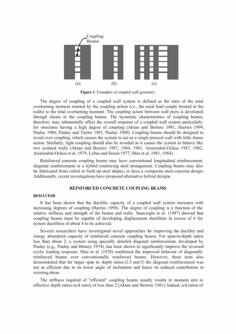
Figure 2. Examples of reinforced concrete coupling beams (Harries et al. 1998).
Conventional reinforcement, i.e., longitudinal bars with transverse steel (see Figure 2a),
performs satisfactorily at nominal shear stresses of 'f 25.0 c ( 'f 3 c ) or less when the
flexural mode controls the failure mechanism (Aktan and Bertero 1981, Aristizabal-Ochoa1987). Sliding shear at the face of the wall begins to affect the response of the beams in the
range of 'f 3.0 c ( 'f 5.3 c ) to 'f 5.0 c ( 'f 6 c ). By providing intermediate midheight
longitudinal bars, the hysteretic response is improved and strength deterioration due to shear
is delayed (Aktan and Bertero 1984, Scriber and Wight 1978, Tassios et al. 1996). Beams
with intermediate bars do not perform well when the shear stress is greater than 'f 5.0 c
( 'f 6 c ). Providing cranked diagonal reinforcement near the beam ends has been shown to
improve the hysteretic behavior by preventing sliding shear, and by spreading the hinging
regions away from the wall face (Paparoni 1972, Aristizabal-Ochoa 1987). This detail,
however, poses construction difficulties and results in extra cost.
8 - No 25
8 - No 25
2 - No 15
midside 7 0 0 m m
400 mm
No 10 hoops@ 90 mm
4 - No 30 in No 10 hoops@ 100 mm
4 - No 30 in No 10 hoops@ 100 mm
7
0 0 m m
400 mm
No 10 hoops@ 300 mm
(a) Conventionally reinforced coupling beam
(b) Diagonally reinforced coupling beam
3000 mm 1.3l =1200 mm
d
1200 mm
1.3l = 1450 mmd
wall steelnot shown
wall steelnot shown
8/14/2019 Behavior and Design of Reinforced Concrete.pdf
http://slidepdf.com/reader/full/behavior-and-design-of-reinforced-concretepdf 5/27
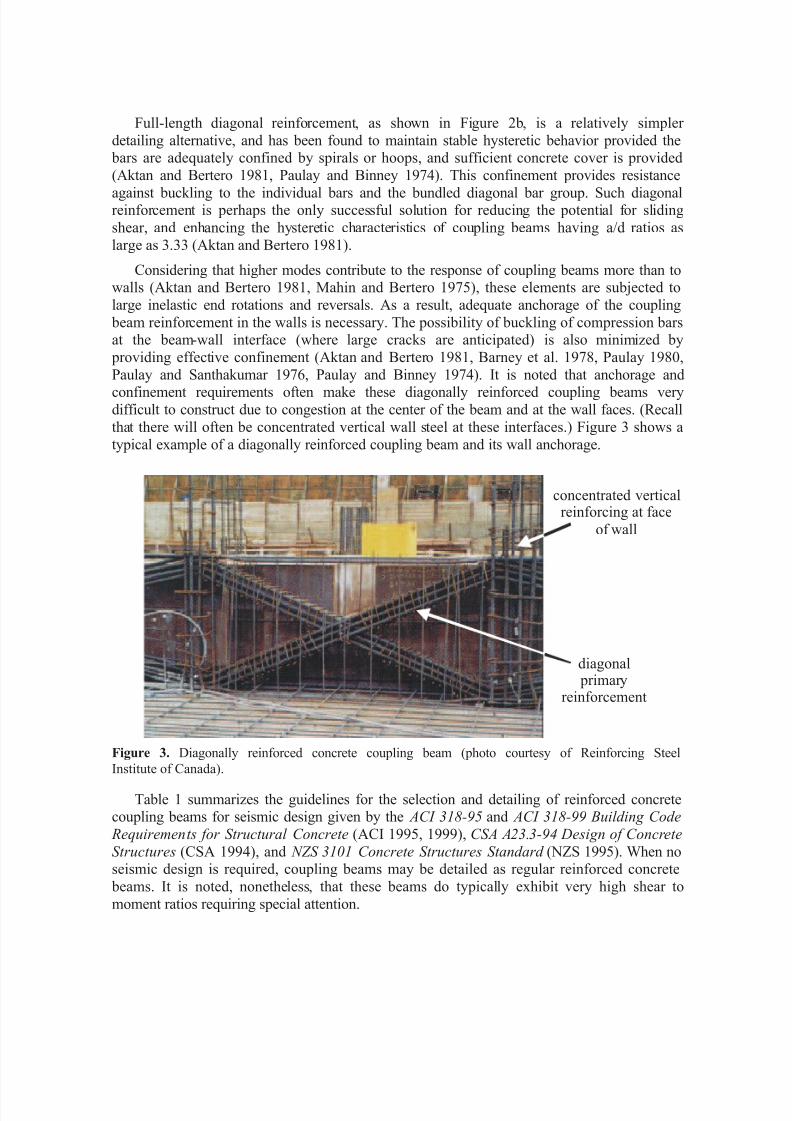
Full-length diagonal reinforcement, as shown in Figure 2b, is a relatively simpler
detailing alternative, and has been found to maintain stable hysteretic behavior provided the bars are adequately confined by spirals or hoops, and sufficient concrete cover is provided
(Aktan and Bertero 1981, Paulay and Binney 1974). This confinement provides resistance
against buckling to the individual bars and the bundled diagonal bar group. Such diagonalreinforcement is perhaps the only successful solution for reducing the potential for sliding
shear, and enhancing the hysteretic characteristics of coupling beams having a/d ratios as
large as 3.33 (Aktan and Bertero 1981).
Considering that higher modes contribute to the response of coupling beams more than towalls (Aktan and Bertero 1981, Mahin and Bertero 1975), these elements are subjected to
large inelastic end rotations and reversals. As a result, adequate anchorage of the coupling
beam reinforcement in the walls is necessary. The possibility of buckling of compression barsat the beam-wall interface (where large cracks are anticipated) is also minimized by
providing effective confinement (Aktan and Bertero 1981, Barney et al. 1978, Paulay 1980,
Paulay and Santhakumar 1976, Paulay and Binney 1974). It is noted that anchorage andconfinement requirements often make these diagonally reinforced coupling beams very
difficult to construct due to congestion at the center of the beam and at the wall faces. (Recall
that there will often be concentrated vertical wall steel at these interfaces.) Figure 3 shows a
typical example of a diagonally reinforced coupling beam and its wall anchorage.
Figure 3. Diagonally reinforced concrete coupling beam (photo courtesy of Reinforcing Steel
Institute of Canada).
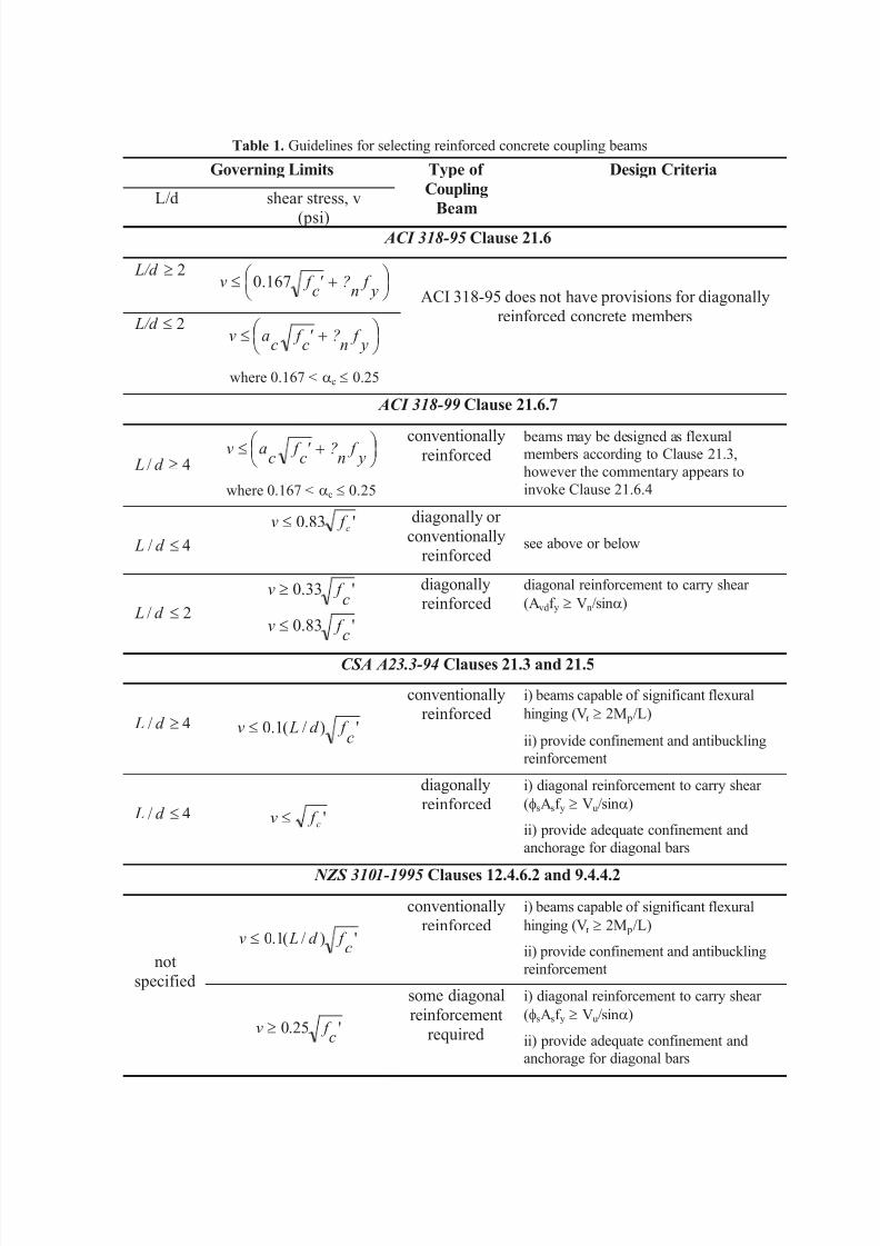
Table 1 summarizes the guidelines for the selection and detailing of reinforced concretecoupling beams for seismic design given by the ACI 318-95 and ACI 318-99 Building Code
Requirements for Structural Concrete (ACI 1995, 1999), CSA A23.3-94 Design of Concrete
Structures (CSA 1994), and NZS 3101 Concrete Structures Standard (NZS 1995). When noseismic design is required, coupling beams may be detailed as regular reinforced concrete
beams. It is noted, nonetheless, that these beams do typically exhibit very high shear to
moment ratios requiring special attention.
concentrated verticalreinforcing at face
of wall
diagonal primary
reinforcement
8/14/2019 Behavior and Design of Reinforced Concrete.pdf
http://slidepdf.com/reader/full/behavior-and-design-of-reinforced-concretepdf 6/27
Table 1. Guidelines for selecting reinforced concrete coupling beams
Governing Limits
L/d shear stress, v
(psi)
Type of
Coupling
Beam
Design Criteria
ACI 318-95 Clause 21.6
2³ L/d ÷ ø öç
è æ +£
y f
n?'
c f v 167.0
2£ L/d ÷ ø öç
è æ +£
y f
n?'
c f
cav
where 0.167 < ac £ 0.25
ACI 318-95 does not have provisions for diagonally
reinforced concrete members
ACI 318-99 Clause 21.6.7
4/ ³d L÷ ø öç
è æ +£
y f
n?'
c f
cav
where 0.167 < ac £ 0.25
conventionally
reinforced beams may be designed as flexural
members according to Clause 21.3,
however the commentary appears to
invoke Clause 21.6.4
4/ £d L
'83.0 c f v £ diagonally or
conventionallyreinforced
see above or below
2/ £d L'83.0
'33.0
c f v
c f v
£
³ diagonallyreinforced
diagonal reinforcement to carry shear
(Avdf y ³ Vn/sina)
CSA A23.3-94 Clauses 21.3 and 21.5
4/ ³d L ')/(1.0c
f d Lv £
conventionallyreinforced
i) beams capable of significant flexural
hinging (Vr ³ 2M p/L)
ii) provide confinement and antibuckling
reinforcement
4/ £d L 'c f v £
diagonally
reinforced
i) diagonal reinforcement to carry shear
(fsAsf y ³ Vu/sina)
ii) provide adequate confinement and
anchorage for diagonal bars
NZS 3101-1995 Clauses 12.4.6.2 and 9.4.4.2
')/(1.0c
f d Lv £
conventionallyreinforced
i) beams capable of significant flexural
hinging (Vr ³ 2M p/L)
ii) provide confinement and antibuckling
reinforcementnot
specified
'25.0c
f v ³
some diagonal
reinforcement
required
i) diagonal reinforcement to carry shear
(fsAsf y ³ Vu/sina)
ii) provide adequate confinement and
anchorage for diagonal bars
8/14/2019 Behavior and Design of Reinforced Concrete.pdf
http://slidepdf.com/reader/full/behavior-and-design-of-reinforced-concretepdf 7/27
The ACI 318-95 seismic provisions do not specifically address details for coupling
beams. Clause 21.6.5.7 limits the nominal shear strength of a “horizontal wall segment” to
'ccp f 0.83A ( '
ccp f 10A ). The accompanying commentary states that the coupling beam is
“in effect, a pier rotated through 90 deg.” Applying this interpretation allows the nominalshear strength of a coupling beam to be determined from Clauses 21.6.5.2 or 21.6.5.3,
depending on the span-to-depth ratio of the beam. If this interpretation is applied, Clause21.6.5.3 permits the shear stress in a very short coupling beam (L/d < 2.0) to be greater than
that in a longer beam. From the previous discussion of coupling beam behavior, it is clear
that this interpretation runs counter to observed beam behavior. ACI 318-95 does not addressdiagonally reinforced concrete beams in any way.
ACI 318-99 has adopted specific provisions for coupling beams. For beams having span-
to-depth ratios, L/d, greater than 4.0, coupling beams are designed as flexural members
satisfying the requirements of Clause 21.3. It is noted, however, that Clause 21.6.4.5(formerly 21.6.5.7 in 318-95) and the accompanying commentary continues to suggest that
“horizontal wall segments” may be treated as “pier[s] rotated through 90 deg.” as discussedabove. For coupling beams having span-to-depth ratios between 2 and 4, Clause 21.6.7.2allows the use of diagonal or conventional reinforcement. For beams having span-to-depth
ratios less than 2 and a factored shear force exceeding 'cf 0.33 ( '
cf 4 ), diagonal
reinforcement is required.
In Table 1, it is noted that the Canadian standard CSA A23.3 provides the clearest
direction as to the use of diagonal reinforcement: diagonal reinforcement requirements are
triggered by both span-to-depth ratios and shear stresses in the beam. The New Zealand
standard NZS 3101, on the other hand, combines these triggers into one: shear stress,normalized by the span-to-depth ratio. NZS 3101 does, however, require diagonal
reinforcement if the shear stress exceeds an absolute threshold value of 'cf 0.25 ( '
cf 3 ).
Furthermore, NZS 3101 Commentary Clause C9.4.4.2 appears to permit shear to be resisted
by a combination of diagonal and conventional reinforcement providing that the contributionof the conventional reinforcement remains below the threshold value. For seismic design, the
New Zealand Standard does recommend, however, that 100% of the shear forces be carried
by diagonal reinforcement in any case where diagonal reinforcement is required. The designand detailing requirements for diagonally reinforced concrete coupling beams are essentially
identical in both the Canadian and New Zealand standards.
ANALYSIS OF WALLS COUPLED WITH REINFORCED CONCRETE COUPLING
BEAMS
Geometric Modeling
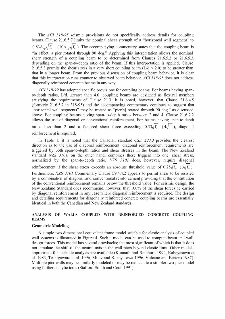
A simple two-dimensional equivalent frame model suitable for elastic analysis of coupled
wall systems is illustrated in Figure 4. Such a model can be used to compute beam and wall
design forces. This model has several drawbacks; the most significant of which is that it doesnot simulate the shift of the neutral axis in the wall piers beyond elastic limit. Other models
appropriate for inelastic analysis are available (Kunnath and Reinhorn 1994, Kabeyasawa et
al. 1983, Teshigawara et al. 1996, Milev and Kabeyasawa 1996, Vulcano and Bertero 1987).Multiple pier walls may be similarly modeled or may be reduced to a simpler two-pier model
using further analytic tools (Stafford-Smith and Coull 1991).
8/14/2019 Behavior and Design of Reinforced Concrete.pdf
http://slidepdf.com/reader/full/behavior-and-design-of-reinforced-concretepdf 8/27
RigidElements
FrameElements
L
Figure 4. Two dimensional equivalent frame model of coupled wall system.
Modeling Beam and Wall Properties
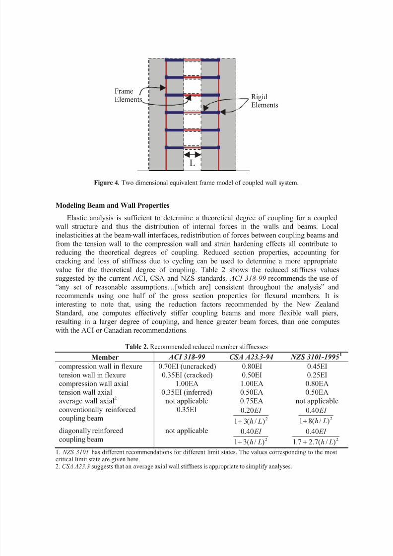
Elastic analysis is sufficient to determine a theoretical degree of coupling for a coupledwall structure and thus the distribution of internal forces in the walls and beams. Local
inelasticities at the beam-wall interfaces, redistribution of forces between coupling beams and
from the tension wall to the compression wall and strain hardening effects all contribute toreducing the theoretical degrees of coupling. Reduced section properties, accounting for
cracking and loss of stiffness due to cycling can be used to determine a more appropriate
value for the theoretical degree of coupling. Table 2 shows the reduced stiffness valuessuggested by the current ACI, CSA and NZS standards. ACI 318-99 recommends the use of
“any set of reasonable assumptions…[which are] consistent throughout the analysis” andrecommends using one half of the gross section properties for flexural members. It isinteresting to note that, using the reduction factors recommended by the New Zealand
Standard, one computes effectively stiffer coupling beams and more flexible wall piers,
resulting in a larger degree of coupling, and hence greater beam forces, than one computes
with the ACI or Canadian recommendations.
Table 2. Recommended reduced member stiffnesses
Member ACI 318-99 CSA A23.3-94 NZS 3101-1995 1
compression wall in flexure 0.70EI (uncracked) 0.80EI 0.45EI
tension wall in flexure 0.35EI (cracked) 0.50EI 0.25EI
compression wall axial 1.00EA 1.00EA 0.80EAtension wall axial 0.35EI (inferred) 0.50EA 0.50EA
average wall axial2
not applicable 0.75EA not applicableconventionally reinforced
coupling beam
0.35EI2)/(31
20.0
Lh
EI
+ 2)/(81
40.0
Lh
EI
+diagonally reinforced
coupling beam
not applicable2
)/(31
40.0
Lh
EI
+ 2)/(7.27.1
40.0
Lh
EI
+1. NZS 3101 has different recommendations for different limit states. The values corresponding to the mostcritical limit state are given here.2. CSA A23.3 suggests that an average axial wall stiffness is appropriate to simplify analyses.
8/14/2019 Behavior and Design of Reinforced Concrete.pdf
http://slidepdf.com/reader/full/behavior-and-design-of-reinforced-concretepdf 9/27
Design
As shown in Table 1, depending on the shear span, coupling beams are designeddifferently.
Flexural Failure Mode
Coupling beams are designed and detailed as standard beams if both L/d ³ 4 and
d b'f 0.33V wcu £ ( d b'f 4V wcu £ ). If the structure is located in high seismic regions (UBC
Zone 4, NEHRP Seismic Design Category D or E), provisions from ACI 318-99 Section 21.3
are used. ACI 318-99 Section 21.9 is followed for structures in moderate seismic regions
(UBC Zone 3, NEHRP Seismic Design Category C). It is noted that ACI 318-99 provisionsfor minimum beam width (Clauses 21.3.1.3 and 21.3.1.4) may be waived if rational analysis
shows that lateral stability of the beam is adequate, or lateral stability is provided by
alternative means. Often the provision of an integral slab will be sufficient to provide lateralstability.
The longitudinal flexural bars in the beam should be anchored adequately in the wall
piers. For high seismic regions (UBC Zone 4, NEHRP Seismic Design Category D or E),
development length requirements in ACI 318-99 Clause 21.5.4 must be met in addition tothose in ACI 318-99 Chapter 12. For moderate seismic regions (UBC Zone 3, NEHRP
Seismic Design Category C), development lengths for the longitudinal bars based on ACI
318-99 Chapter 12 are considered sufficient.
Shear Failure Mode
If L/d < 4 and d b'f 0.33V wcu > ( d b'f 4V wcu > ), two intersecting groups of diagonal
bars are to be used to reinforce coupling beams. Although it is preferable for eachintersecting group to contain the same number and size of reinforcing bar, this is often not practical. Where this is the case, it is necessary to ensure that the amount of steel provided in
each diagonal is the same. If L/d < 4 and d b'f 0.33V wcu < ( d b'f 4V wcu < ), diagonal
reinforcement may also be used. Each group of diagonal bars must have a minimum of four bars placed in a core with a minimum depth and width equal to the greater of bw/5 in the
plane of the diagonal bars or bw/2 in the plane of the beam ( ACI 318-99 Clause 21.6.7.4 (a)).
The diagonal bars must be confined according to ACI 318-99 clauses 21.4.4.1 through21.4.4.3. The required area of one leg of the diagonal reinforcement, Avd is ( ACI 318-99
Clause 21.6.7.4):
d b f f AV wc yvd n '83.0sin2 £= α (1)
Although the diagonal reinforcement is intended to prevent sliding shear, the value of
coupling beam shear is limited to d b f wc '83.0 ( d b f wc '10 ). Minimum horizontal and
vertical reinforcement requirements for deep beams ( ACI 318-99 clauses 11.8.9 and 11.8.10)
must also be respected.
Considering the importance of adequate anchorage for the diagonal bars, it has been
recommended that the development length, calculated based on Chapter 21 of ACI 318-99,inside the wall piers be increased by as much as 50%, if possible (Paulay 1986). Although
there are no provisions in the Standards for increasing the development length, it is
recommended that these bars be considered as “top cast” bars and that appropriate factors be
8/14/2019 Behavior and Design of Reinforced Concrete.pdf
http://slidepdf.com/reader/full/behavior-and-design-of-reinforced-concretepdf 10/27
applied as shown in Figure 2 (Harries et al. 1998). Often geometric constraints within the
wall will require that these bars be provided with bent or hooked anchorages (see Figure 3).As previously stated, this detail may be very difficult to construct.
STEEL OR STEEL-CONCRETE COMPOSITE COUPLING BEAMS
Structural steel members provide a viable alternative to reinforced concrete coupling beams. Furthermore, a steel member may be encased with varying levels of longitudinal and
transverse reinforcement. The resulting steel-concrete coupling beams are referred to as
composite coupling beams herein. The advantages of steel or composite coupling beams become particularly apparent in cases where height restrictions do not permit the use of deep
reinforced concrete beams, or where the required capacities and stiffness cannot be
developed economically by a concrete beam.
Similar to reinforced concrete coupling beams, energy dissipation characteristics of steelor composite coupling beams play an important role in the overall performance. Depending
on the coupling beam length, steel coupling beams may be detailed to dissipate a major portion of the input energy by flexure or by shear. For most coupling beams, however, it ismore advantageous to design the coupling beams as “shear critical,” or shear yielding
members since such members exhibit a more desirable mode of energy dissipation. Such a
choice is not possible for reinforced concrete members.
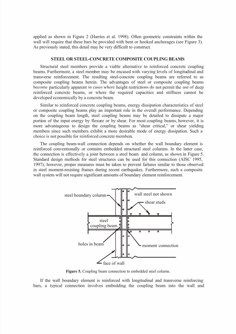
The coupling beam-wall connection depends on whether the wall boundary element isreinforced conventionally or contains embedded structural steel columns. In the latter case,
the connection is effectively a joint between a steel beam and column, as shown in Figure 5.
Standard design methods for steel structures can be used for this connection (AISC 1995,1997); however, proper measures must be taken to prevent failures similar to those observed
in steel moment-resisting frames during recent earthquakes. Furthermore, such a composite
wall system will not require significant amounts of boundary element reinforcement.
steel boundary column
shear studs
moment connection
face of wall
steelcoupling beam
holes in beam
wall steel not shown
Figure 5. Coupling beam connection to embedded steel column.
If the wall boundary element is reinforced with longitudinal and transverse reinforcing
bars, a typical connection involves embedding the coupling beam into the wall and
8/14/2019 Behavior and Design of Reinforced Concrete.pdf
http://slidepdf.com/reader/full/behavior-and-design-of-reinforced-concretepdf 11/27
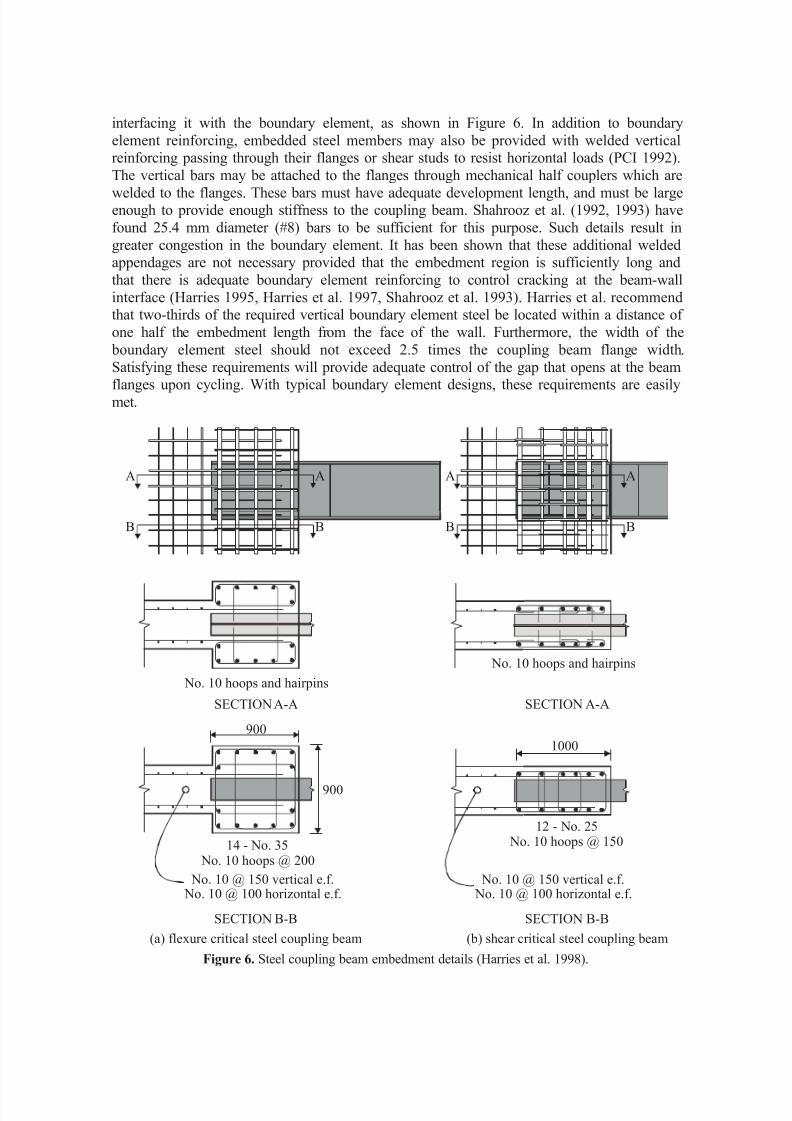
interfacing it with the boundary element, as shown in Figure 6. In addition to boundary
element reinforcing, embedded steel members may also be provided with welded verticalreinforcing passing through their flanges or shear studs to resist horizontal loads (PCI 1992).
The vertical bars may be attached to the flanges through mechanical half couplers which are
welded to the flanges. These bars must have adequate development length, and must be largeenough to provide enough stiffness to the coupling beam. Shahrooz et al. (1992, 1993) have
found 25.4 mm diameter (#8) bars to be sufficient for this purpose. Such details result in
greater congestion in the boundary element. It has been shown that these additional weldedappendages are not necessary provided that the embedment region is sufficiently long and
that there is adequate boundary element reinforcing to control cracking at the beam-wall
interface (Harries 1995, Harries et al. 1997, Shahrooz et al. 1993). Harries et al. recommendthat two-thirds of the required vertical boundary element steel be located within a distance of
one half the embedment length from the face of the wall. Furthermore, the width of the
boundary element steel should not exceed 2.5 times the coupling beam flange width.
Satisfying these requirements will provide adequate control of the gap that opens at the beam
flanges upon cycling. With typical boundary element designs, these requirements are easilymet.
Figure 6. Steel coupling beam embedment details (Harries et al. 1998).
No. 10 hoops and hairpins
No. 10 hoops and hairpins
SECTION A-A
SECTION B-B
SECTION A-A
SECTION B-B
A A
B B
A A
B B
(a) flexure critical steel coupling beam (b) shear critical steel coupling beam
900
900
1000
14 - No. 35 No. 10 hoops @ 200
12 - No. 25 No. 10 hoops @ 150
No. 10 @ 150 vertical e.f. No. 10 @ 100 horizontal e.f.
No. 10 @ 150 vertical e.f. No. 10 @ 100 horizontal e.f.
8/14/2019 Behavior and Design of Reinforced Concrete.pdf
http://slidepdf.com/reader/full/behavior-and-design-of-reinforced-concretepdf 12/27
As is illustrated in Figure 6a, lighter “flexure critical” coupling beams require more
boundary element steel in the wall since a greater proportion of the overturning moment iscarried by the wall. This may also result in the need to provide “barbells” at the toes of the
walls, further complicating construction.
It is not necessary, nor is it practical, to pass boundary element reinforcing through the
web of the embedded coupling beam. It is however necessary to provide good confinement inthe region of the embedded web. This may be accomplished using hairpins and cross ties
parallel to the web as shown in Figure 6 (section A-A). Additionally, vertical boundary
element reinforcement in this region may also be relied upon to provide significantconfinement to the embedded region (Harries et al. 1997).
STEEL-CONCRETE COMPOSITE COUPLING BEAMS
The selection of the embedded steel beam in a composite coupling beam typicallyneglects the contribution of the encasing concrete. The contribution of the encasing concrete,
however, must be accounted for in subsequent stiffness and embedment length calculations.The presence of the encasing concrete does permit the detailing requirements of theembedded member to be relaxed. Gong and Shahrooz (1998) have shown that stiffeners are
not required in the case of a composite coupling beam. The surrounding concrete is sufficient
to provide adequate stability and thus ductility to the embedded steel beam.
ANALYSIS OF WALLS COUPLED WITH STEEL OR STEEL-CONCRETE COMPOSITE
COUPLING BEAMS
Stiffness
For steel coupling beams, standard methods are used to calculate the stiffness. The
stiffness of steel-concrete composite coupling beams needs to account for the increasedstiffness due to encasement. Stiffness based on gross transformed sections should be used to
calculate the upper bound values of demands in the walls, most notably wall axial force. The
cracked transformed section moment of inertia may be used when deflection limits or coupling beam shear angles are checked. A previous study indicates that the additional
stiffness due to the presence of a composite floor slab is lost shortly after coupling beams
undergo small deformations (Shahrooz and Gong 1998). Until additional experimental data become available, it is recommended to include the participation of the floor slab when the
stiffness of steel-concrete composite coupling beams are computed. Effective flange width
for T beams as specified in ACI 8.10.2 may be used for this purpose. Deflection limits should
be checked neglecting the contribution of the floor slab.
Geometric Modeling
Previous studies (Shahrooz et al. 1992, 1993, Gong et al. 1997, 1998, Harries et al. 1997)suggest that steel or steel-concrete composite coupling beams are not fixed at the face of the
wall. As part of design calculations, the additional flexibility needs to be taken into account
to ensure that wall forces and lateral deflections are computed with reasonable accuracy.
Based on experimental data (Shahrooz et al. 1992, 1993, Gong et al. 1997, 1998), the“effective fixed point” of steel or steel-concrete composite coupling beams may be taken as
approximately one-third of the embedment length from the face of the wall. Thus, the
effective clear span, L of the frame element representing the coupling beam in the modelshown in Figure 4 is:
8/14/2019 Behavior and Design of Reinforced Concrete.pdf
http://slidepdf.com/reader/full/behavior-and-design-of-reinforced-concretepdf 13/27
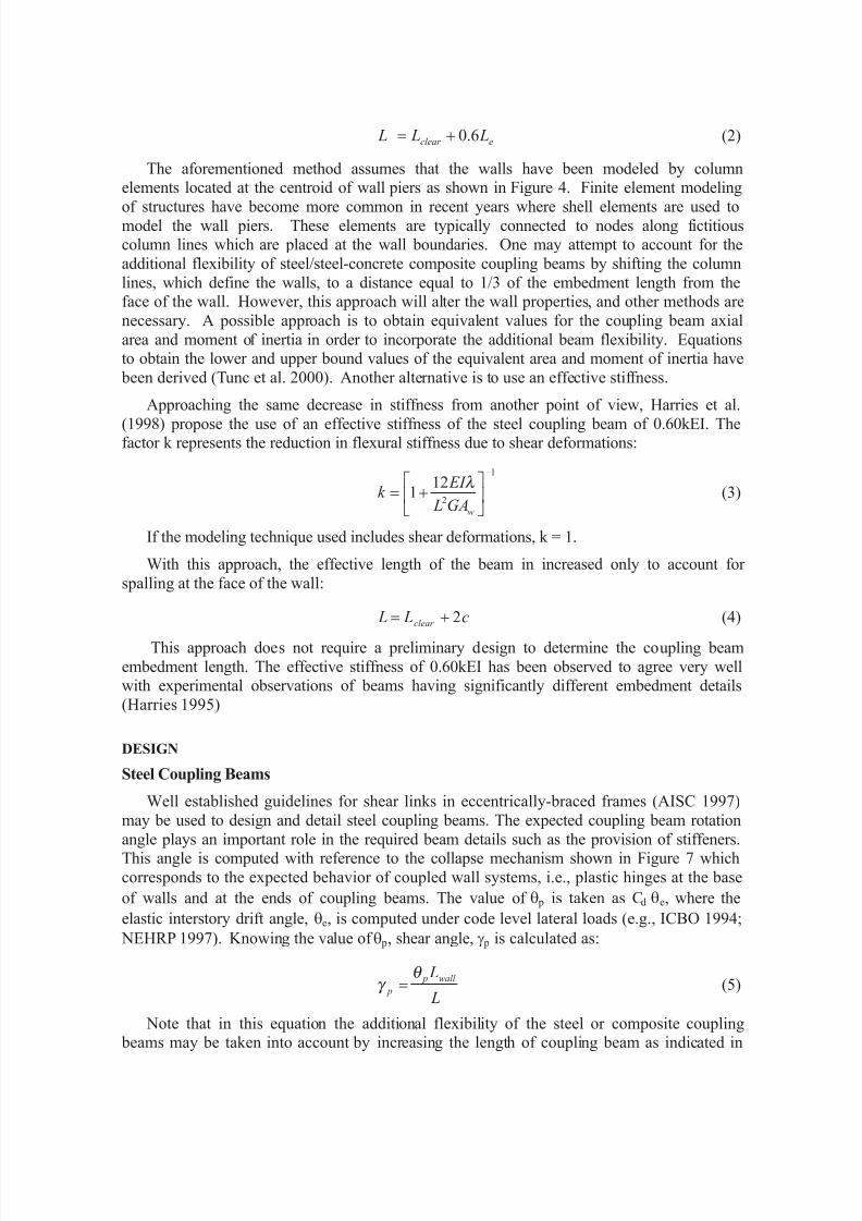
eclear L L L 6.0+= (2)
The aforementioned method assumes that the walls have been modeled by columnelements located at the centroid of wall piers as shown in Figure 4. Finite element modeling
of structures have become more common in recent years where shell elements are used tomodel the wall piers. These elements are typically connected to nodes along fictitiouscolumn lines which are placed at the wall boundaries. One may attempt to account for the
additional flexibility of steel/steel-concrete composite coupling beams by shifting the column
lines, which define the walls, to a distance equal to 1/3 of the embedment length from theface of the wall. However, this approach will alter the wall properties, and other methods are
necessary. A possible approach is to obtain equivalent values for the coupling beam axial
area and moment of inertia in order to incorporate the additional beam flexibility. Equationsto obtain the lower and upper bound values of the equivalent area and moment of inertia have
been derived (Tunc et al. 2000). Another alternative is to use an effective stiffness.
Approaching the same decrease in stiffness from another point of view, Harries et al.
(1998) propose the use of an effective stiffness of the steel coupling beam of 0.60kEI. Thefactor k represents the reduction in flexural stiffness due to shear deformations:
1
2
121
-
úû
ùêë
é+=
wGA L
EI k
λ (3)
If the modeling technique used includes shear deformations, k = 1.
With this approach, the effective length of the beam in increased only to account for
spalling at the face of the wall:
c L L clear 2+= (4)
This approach does not require a preliminary design to determine the coupling beam
embedment length. The effective stiffness of 0.60kEI has been observed to agree very wellwith experimental observations of beams having significantly different embedment details
(Harries 1995)
DESIGN
Steel Coupling Beams
Well established guidelines for shear links in eccentrically-braced frames (AISC 1997)
may be used to design and detail steel coupling beams. The expected coupling beam rotation
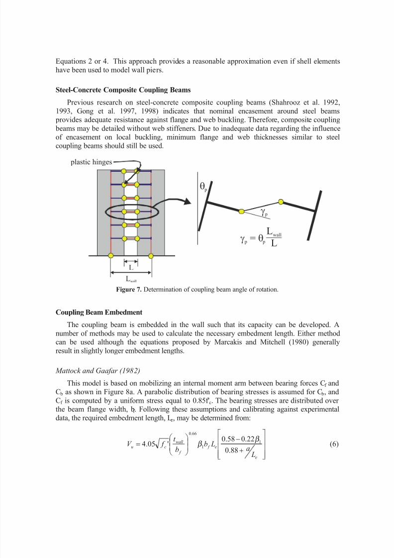
angle plays an important role in the required beam details such as the provision of stiffeners.This angle is computed with reference to the collapse mechanism shown in Figure 7 which
corresponds to the expected behavior of coupled wall systems, i.e., plastic hinges at the base
of walls and at the ends of coupling beams. The value of q p is taken as Cd qe, where the
elastic interstory drift angle, qe, is computed under code level lateral loads (e.g., ICBO 1994;
NEHRP 1997). Knowing the value of q p, shear angle, g p is calculated as:
L
Lwall p
p
θ γ = (5)
Note that in this equation the additional flexibility of the steel or composite coupling beams may be taken into account by increasing the length of coupling beam as indicated in
8/14/2019 Behavior and Design of Reinforced Concrete.pdf
http://slidepdf.com/reader/full/behavior-and-design-of-reinforced-concretepdf 14/27
Equations 2 or 4. This approach provides a reasonable approximation even if shell elements
have been used to model wall piers.
Steel-Concrete Composite Coupling Beams
Previous research on steel-concrete composite coupling beams (Shahrooz et al. 1992,
1993, Gong et al. 1997, 1998) indicates that nominal encasement around steel beams provides adequate resistance against flange and web buckling. Therefore, composite coupling
beams may be detailed without web stiffeners. Due to inadequate data regarding the influence
of encasement on local buckling, minimum flange and web thicknesses similar to steelcoupling beams should still be used.
Figure 7. Determination of coupling beam angle of rotation.
Coupling Beam Embedment
The coupling beam is embedded in the wall such that its capacity can be developed. A
number of methods may be used to calculate the necessary embedment length. Either methodcan be used although the equations proposed by Marcakis and Mitchell (1980) generally
result in slightly longer embedment lengths.
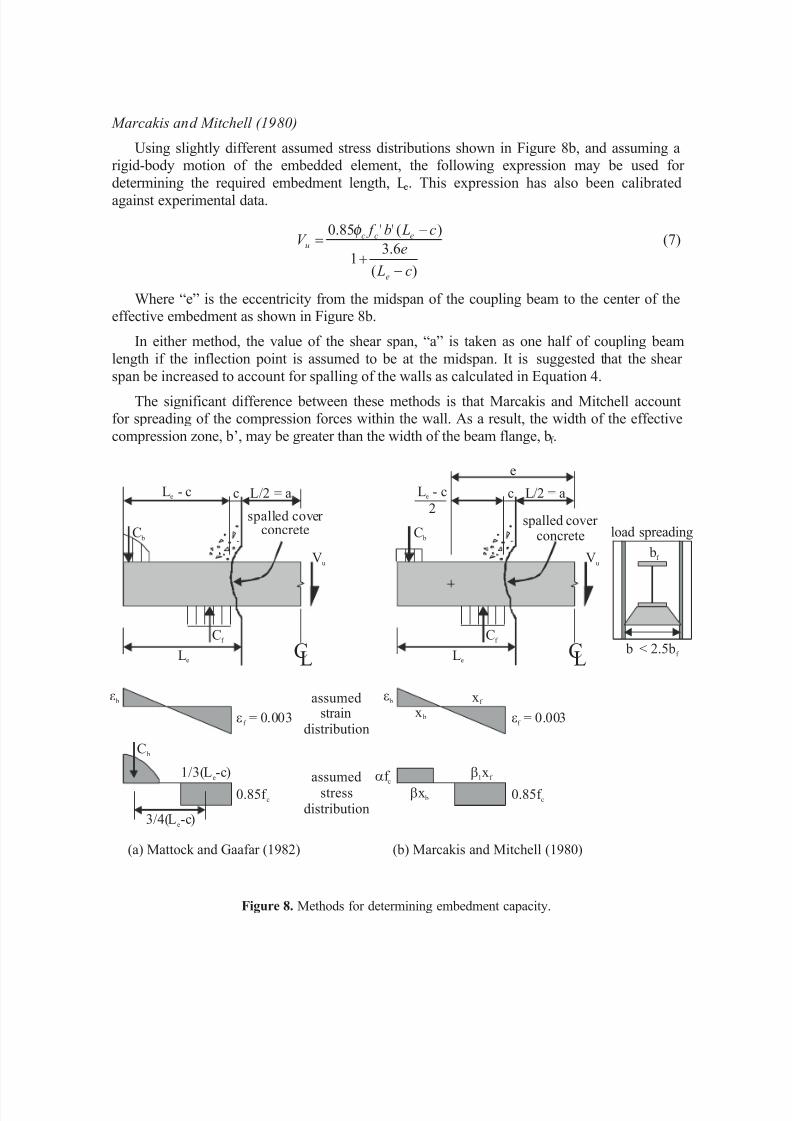
Mattock and Gaafar (1982)
This model is based on mobilizing an internal moment arm between bearing forces Cf andC b as shown in Figure 8a. A parabolic distribution of bearing stresses is assumed for C b, and
Cf is computed by a uniform stress equal to 0.85f'c. The bearing stresses are distributed overthe beam flange width, bf . Following these assumptions and calibrating against experimental
data, the required embedment length, Le, may be determined from:
úúú
û
ù
êêê
ë
é
+
-÷÷ ø
öççè
æ =
e
e f
f
wall cu
La
Lbb
t f V
88.0
22.058.0'05.4 1
1
66.0
β β (6)
L
Lwall
g p
q p
g q p p=L
Lwall
plastic hinges
8/14/2019 Behavior and Design of Reinforced Concrete.pdf
http://slidepdf.com/reader/full/behavior-and-design-of-reinforced-concretepdf 15/27
Marcakis and Mitchell (1980)
Using slightly different assumed stress distributions shown in Figure 8b, and assuming arigid-body motion of the embedded element, the following expression may be used for
determining the required embedment length, Le. This expression has also been calibrated
against experimental data.
)(
6.31
)(''85.0
c L
e
c Lb f V
e
eccu
-+
-=
φ (7)
Where “e” is the eccentricity from the midspan of the coupling beam to the center of theeffective embedment as shown in Figure 8b.
In either method, the value of the shear span, “a” is taken as one half of coupling beam
length if the inflection point is assumed to be at the midspan. It is suggested that the shear
span be increased to account for spalling of the walls as calculated in Equation 4.
The significant difference between these methods is that Marcakis and Mitchell accountfor spreading of the compression forces within the wall. As a result, the width of the effective
compression zone, b’, may be greater than the width of the beam flange, bf .
Figure 8. Methods for determining embedment capacity.
cc L/2 = aL/2 = a
e
VuVu
spalled cover concrete
CC LL
L - c
2eL - ce
LeLe
C bC b
Cf Cf
ef = 0.003ef = 0.003
e be b xf
b1xf 1/3(L -c)e
x b
bx b 0.85f c0.85f c
af c
b < 2.5bf
bf
C b
3/4(L -c)e
assumedstrain
distribution
assumedstress
distribution
(a) Mattock and Gaafar (1982) (b) Marcakis and Mitchell (1980)
spalled cover concrete load spreading
8/14/2019 Behavior and Design of Reinforced Concrete.pdf
http://slidepdf.com/reader/full/behavior-and-design-of-reinforced-concretepdf 16/27
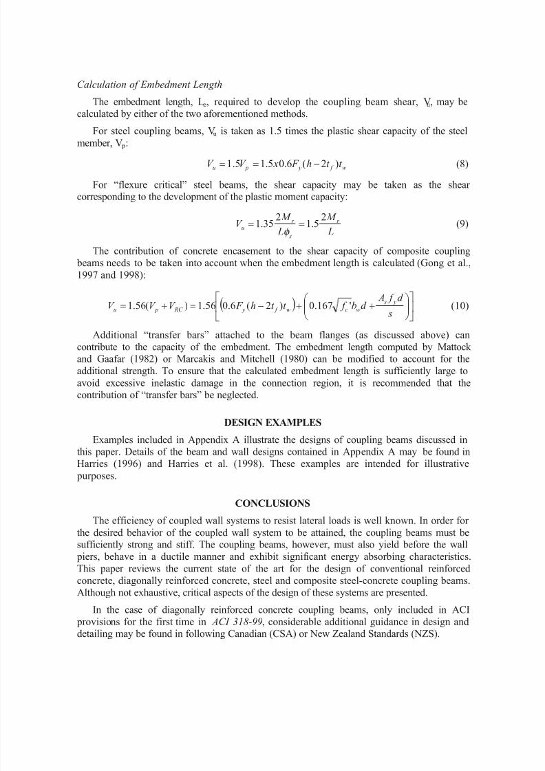
Calculation of Embedment Length
The embedment length, Le, required to develop the coupling beam shear, Vu, may becalculated by either of the two aforementioned methods.
For steel coupling beams, Vu is taken as 1.5 times the plastic shear capacity of the steelmember, V p:
w f y pu t t h F xV V )2(6.05.15.1 -== (8)
For “flexure critical” steel beams, the shear capacity may be taken as the shear corresponding to the development of the plastic moment capacity:
L
M
L
M V r
s
r u
25.1
235.1 ==
φ (9)
The contribution of concrete encasement to the shear capacity of composite coupling
beams needs to be taken into account when the embedment length is calculated (Gong et al.,1997 and 1998):
( ) úû
ùêë
é÷÷ ø
öççè
æ ++-=+=
s
d f Ad b f t t h F V V V
y s
wcw f y RC pu '167.0)2(6.056.1)(56.1 (10)
Additional “transfer bars” attached to the beam flanges (as discussed above) can
contribute to the capacity of the embedment. The embedment length computed by Mattock and Gaafar (1982) or Marcakis and Mitchell (1980) can be modified to account for the
additional strength. To ensure that the calculated embedment length is sufficiently large to
avoid excessive inelastic damage in the connection region, it is recommended that the
contribution of “transfer bars” be neglected.
DESIGN EXAMPLES
Examples included in Appendix A illustrate the designs of coupling beams discussed inthis paper. Details of the beam and wall designs contained in Appendix A may be found in
Harries (1996) and Harries et al. (1998). These examples are intended for illustrative
purposes.
CONCLUSIONS
The efficiency of coupled wall systems to resist lateral loads is well known. In order for
the desired behavior of the coupled wall system to be attained, the coupling beams must besufficiently strong and stiff. The coupling beams, however, must also yield before the wall
piers, behave in a ductile manner and exhibit significant energy absorbing characteristics.
This paper reviews the current state of the art for the design of conventional reinforced
concrete, diagonally reinforced concrete, steel and composite steel-concrete coupling beams.Although not exhaustive, critical aspects of the design of these systems are presented.
In the case of diagonally reinforced concrete coupling beams, only included in ACI
provisions for the first time in ACI 318-99, considerable additional guidance in design anddetailing may be found in following Canadian (CSA) or New Zealand Standards (NZS).

8/14/2019 Behavior and Design of Reinforced Concrete.pdf
http://slidepdf.com/reader/full/behavior-and-design-of-reinforced-concretepdf 17/27
Steel coupling beams may be efficiently designed and detailed as link beams in
eccentrically braced frames. When encased in concrete, considerable stability is imparted tothe beam allowing simplified details to be used.
The proper design of any coupled system must ensure the desired hierarchy of hinging. In
addition it is critical that hinges in the coupling beam remain in their clear span and do not
propagate into the walls. As such proper design of the embedment region is critical. There area number of methods of determining the required embedment length and details of steel or
composite coupling beams. All of these methods are based on an assumed rigid body rotation
of the embedment region of the coupling beam.
8/14/2019 Behavior and Design of Reinforced Concrete.pdf
http://slidepdf.com/reader/full/behavior-and-design-of-reinforced-concretepdf 18/27
APPENDIX A – COUPLING BEAM DESIGN EXAMPLES
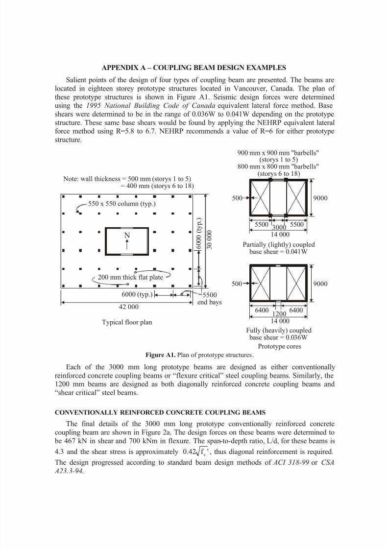
Salient points of the design of four types of coupling beam are presented. The beams are
located in eighteen storey prototype structures located in Vancouver, Canada. The plan of
these prototype structures is shown in Figure A1. Seismic design forces were determinedusing the 1995 National Building Code of Canada equivalent lateral force method. Base
shears were determined to be in the range of 0.036W to 0.041W depending on the prototype
structure. These same base shears would be found by applying the NEHRP equivalent lateralforce method using R=5.8 to 6.7. NEHRP recommends a value of R=6 for either prototype
structure.
Figure A1. Plan of prototype structures.
Each of the 3000 mm long prototype beams are designed as either conventionally
reinforced concrete coupling beams or “flexure critical” steel coupling beams. Similarly, the1200 mm beams are designed as both diagonally reinforced concrete coupling beams and
“shear critical” steel beams.
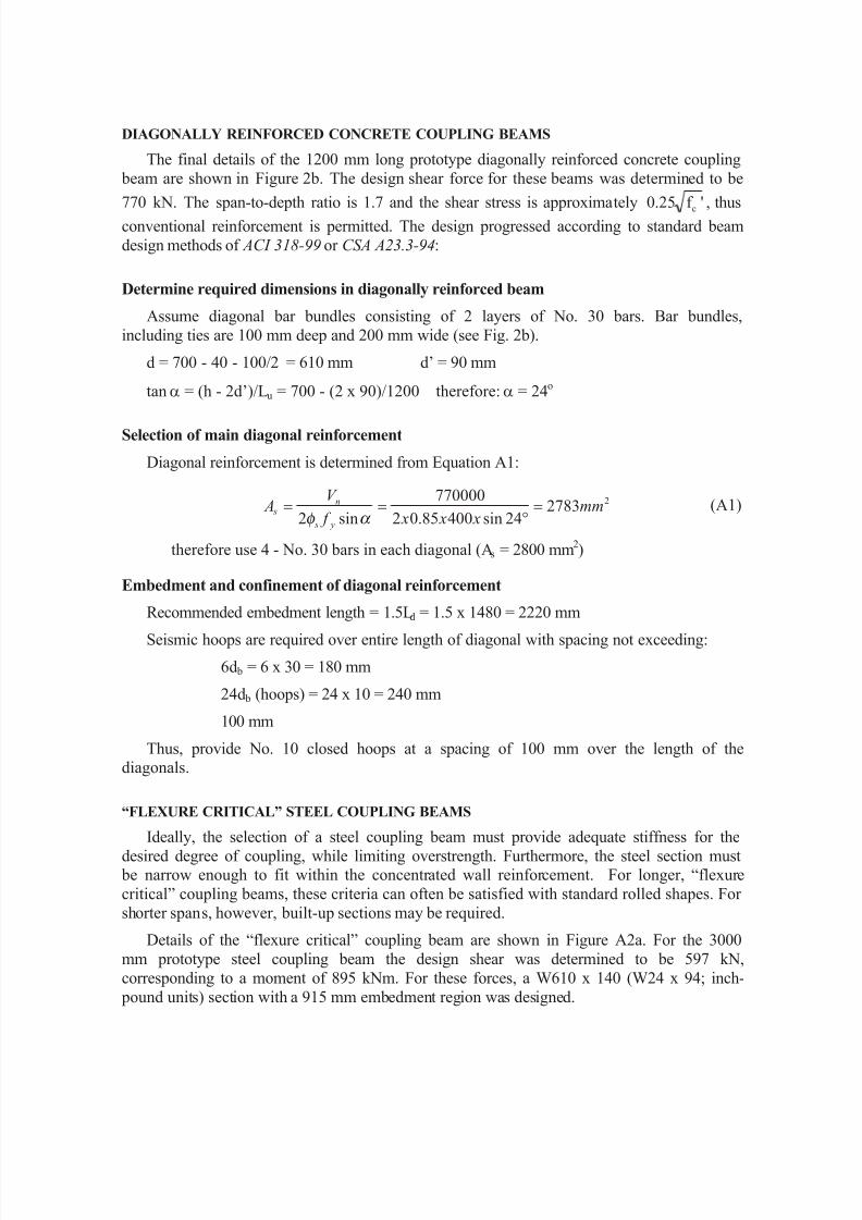
CONVENTIONALLY REINFORCED CONCRETE COUPLING BEAMS
The final details of the 3000 mm long prototype conventionally reinforced concrete
coupling beam are shown in Figure 2a. The design forces on these beams were determined to
be 467 kN in shear and 700 kNm in flexure. The span-to-depth ratio, L/d, for these beams is
4.3 and the shear stress is approximately 'f 42.0 c , thus diagonal reinforcement is required.
The design progressed according to standard beam design methods of ACI 318-99 or CSA
A23.3-94.
Typical floor plan
9000
14 0001200
64006400
500
Fully (heavily) coupled base shear = 0.036W
Prototype cores
Note: wall thickness = 500 mm (storys 1 to 5)
= 400 mm (storys 6 to 18)9000
14 0003000 55005500
500
Partially (lightly) coupled base shear = 0.041W
900 mm x 900 mm "barbells"(storys 1 to 5)
800 mm x 800 mm "barbells"(storys 6 to 18)
42 000
6000 (typ.)
3 0 0 0 0
6 0 0 0 ( t y p . )
550 x 550 column (typ.)
200 mm thick flat plate
N
5500end bays
8/14/2019 Behavior and Design of Reinforced Concrete.pdf
http://slidepdf.com/reader/full/behavior-and-design-of-reinforced-concretepdf 19/27
DIAGONALLY REINFORCED CONCRETE COUPLING BEAMS
The final details of the 1200 mm long prototype diagonally reinforced concrete coupling
beam are shown in Figure 2b. The design shear force for these beams was determined to be
770 kN. The span-to-depth ratio is 1.7 and the shear stress is approximately 'f 25.0 c , thusconventional reinforcement is permitted. The design progressed according to standard beam
design methods of ACI 318-99 or CSA A23.3-94:
Determine required dimensions in diagonally reinforced beam
Assume diagonal bar bundles consisting of 2 layers of No. 30 bars. Bar bundles,
including ties are 100 mm deep and 200 mm wide (see Fig. 2b).
d = 700 - 40 - 100/2 = 610 mm d’ = 90 mm
tan a = (h - 2d’)/Lu = 700 - (2 x 90)/1200 therefore: a = 24o
Selection of main diagonal reinforcement
Diagonal reinforcement is determined from Equation A1:
2278324sin40085.02
770000
sin2mm
x x x f
V A
y s
n s =
°==
α φ (A1)
therefore use 4 - No. 30 bars in each diagonal (As = 2800 mm2)
Embedment and confinement of diagonal reinforcement
Recommended embedment length = 1.5Ld = 1.5 x 1480 = 2220 mm
Seismic hoops are required over entire length of diagonal with spacing not exceeding:
6d b = 6 x 30 = 180 mm
24d b (hoops) = 24 x 10 = 240 mm
100 mm
Thus, provide No. 10 closed hoops at a spacing of 100 mm over the length of thediagonals.
“FLEXURE CRITICAL” STEEL COUPLING BEAMS
Ideally, the selection of a steel coupling beam must provide adequate stiffness for thedesired degree of coupling, while limiting overstrength. Furthermore, the steel section must be narrow enough to fit within the concentrated wall reinforcement. For longer, “flexure
critical” coupling beams, these criteria can often be satisfied with standard rolled shapes. For
shorter spans, however, built-up sections may be required.
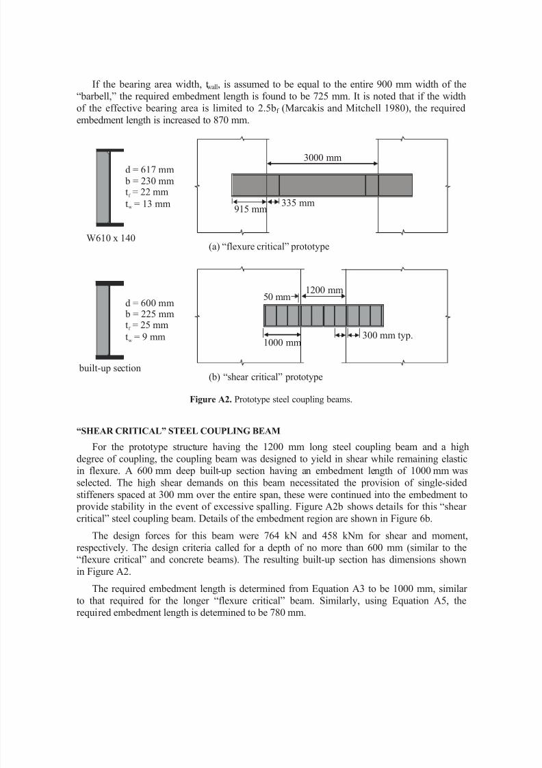
Details of the “flexure critical” coupling beam are shown in Figure A2a. For the 3000
mm prototype steel coupling beam the design shear was determined to be 597 kN,
corresponding to a moment of 895 kNm. For these forces, a W610 x 140 (W24 x 94; inch-
pound units) section with a 915 mm embedment region was designed.
8/14/2019 Behavior and Design of Reinforced Concrete.pdf
http://slidepdf.com/reader/full/behavior-and-design-of-reinforced-concretepdf 20/27
At this point, it is important to verify that the section will indeed behave as expected. In
this case, that it is “flexure critical.” The factored shear capacity is determined to be 1340 kNwhile the shear corresponding to the unfactored probable moment capacity is:
kN x x x x
c L Z F x
c L M y p 734
402300025103005.12
25.12
22 =
+=
+=
+ (A2)
Thus the beam is “flexure critical.”
Required embedment length
The required embedment length is determined from the following relation, (based on
Marcakis and Mitchell, 1980), where the factored shear resistance of the embedment, Vu, is
taken as 1.35Mr /2Lfs = 1.35 x 727 / 0.9 = 1090 kN (see Figure 8b).
)(6.31
)(''85.0
c Le
c Lb f V
e
ecc
u
-+
-=
φ (A3)
Because of the presence of a “barbell” at the wall toe, b’ may be taken as 2.5b =
2.5 x 230 = 575 mm. Taking b’ = 575 mm, e = (3000 + Le + 40) / 2, and c = 40 mm. Solving
Equation A3 yields: Le = 915 mm.
It is necessary to ensure that there is adequate concentrated boundary elementreinforcement, Asc, to develop Ve:
2320640085.0
1090000mm
x f
V A
y s
e sc ===
φ (A4)
This requirement is essentially satisfied, as this steel represents a small portion of what is
required in the region of concentrated reinforcement, and there will typically be someoverstrength provided. Details of the embedment region of this prototype are shown in Figure
6a.
At the beam-wall interface, double-sided stiffeners are provided to simplify the formwork
and to aid in the force transfer between the steel beam and the concrete wall. Due to the highmoment to shear ratio and the need to ensure lateral stability, single-sided stiffeners are
located 335 mm from the face of the wall.
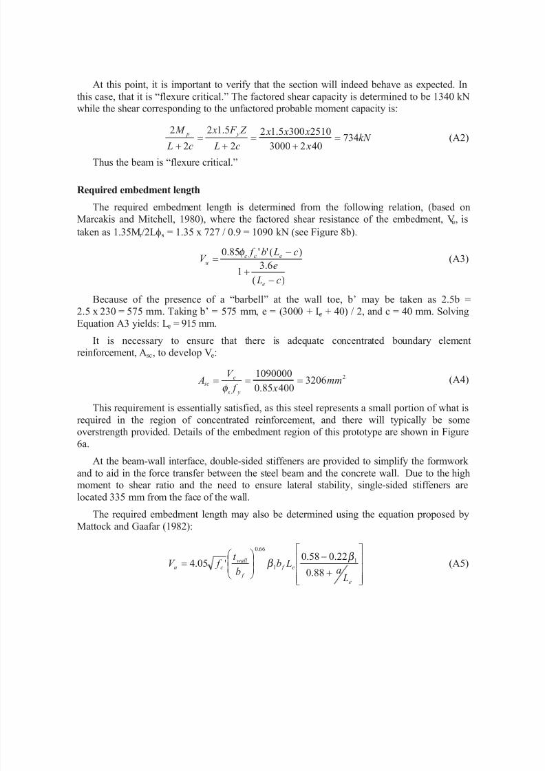
The required embedment length may also be determined using the equation proposed by
Mattock and Gaafar (1982):
úúú
û
ù
êêê
ë
é
+
-÷÷ ø
öççè
æ =
e
e f
f
wall cu
La
Lbb
t f V
88.0
22.058.0'05.4 1
1
66.0
β β (A5)
8/14/2019 Behavior and Design of Reinforced Concrete.pdf
http://slidepdf.com/reader/full/behavior-and-design-of-reinforced-concretepdf 21/27
If the bearing area width, twall, is assumed to be equal to the entire 900 mm width of the
“barbell,” the required embedment length is found to be 725 mm. It is noted that if the widthof the effective bearing area is limited to 2.5b f (Marcakis and Mitchell 1980), the required
embedment length is increased to 870 mm.
Figure A2. Prototype steel coupling beams.
“SHEAR CRITICAL” STEEL COUPLING BEAM
For the prototype structure having the 1200 mm long steel coupling beam and a high
degree of coupling, the coupling beam was designed to yield in shear while remaining elasticin flexure. A 600 mm deep built-up section having an embedment length of 1000 mm was
selected. The high shear demands on this beam necessitated the provision of single-sided
stiffeners spaced at 300 mm over the entire span, these were continued into the embedment to provide stability in the event of excessive spalling. Figure A2b shows details for this “shear
critical” steel coupling beam. Details of the embedment region are shown in Figure 6b.
The design forces for this beam were 764 kN and 458 kNm for shear and moment,
respectively. The design criteria called for a depth of no more than 600 mm (similar to the“flexure critical” and concrete beams). The resulting built-up section has dimensions shown
in Figure A2.
The required embedment length is determined from Equation A3 to be 1000 mm, similar
to that required for the longer “flexure critical” beam. Similarly, using Equation A5, therequired embedment length is determined to be 780 mm.
3000 mm
335 mm915 mm
1200 mm50 mm
1000 mm300 mm typ.
(a) “flexure critical” prototype
(b) “shear critical” prototype
W610 x 140
built-up section
d = 617 mm b = 230 mmt = 22 mm
t = 13 mmf
w
d = 600 mm b = 225 mmt = 25 mm
t = 9 mmf
w
8/14/2019 Behavior and Design of Reinforced Concrete.pdf
http://slidepdf.com/reader/full/behavior-and-design-of-reinforced-concretepdf 22/27
COMPOSITE COUPLING BEAMS
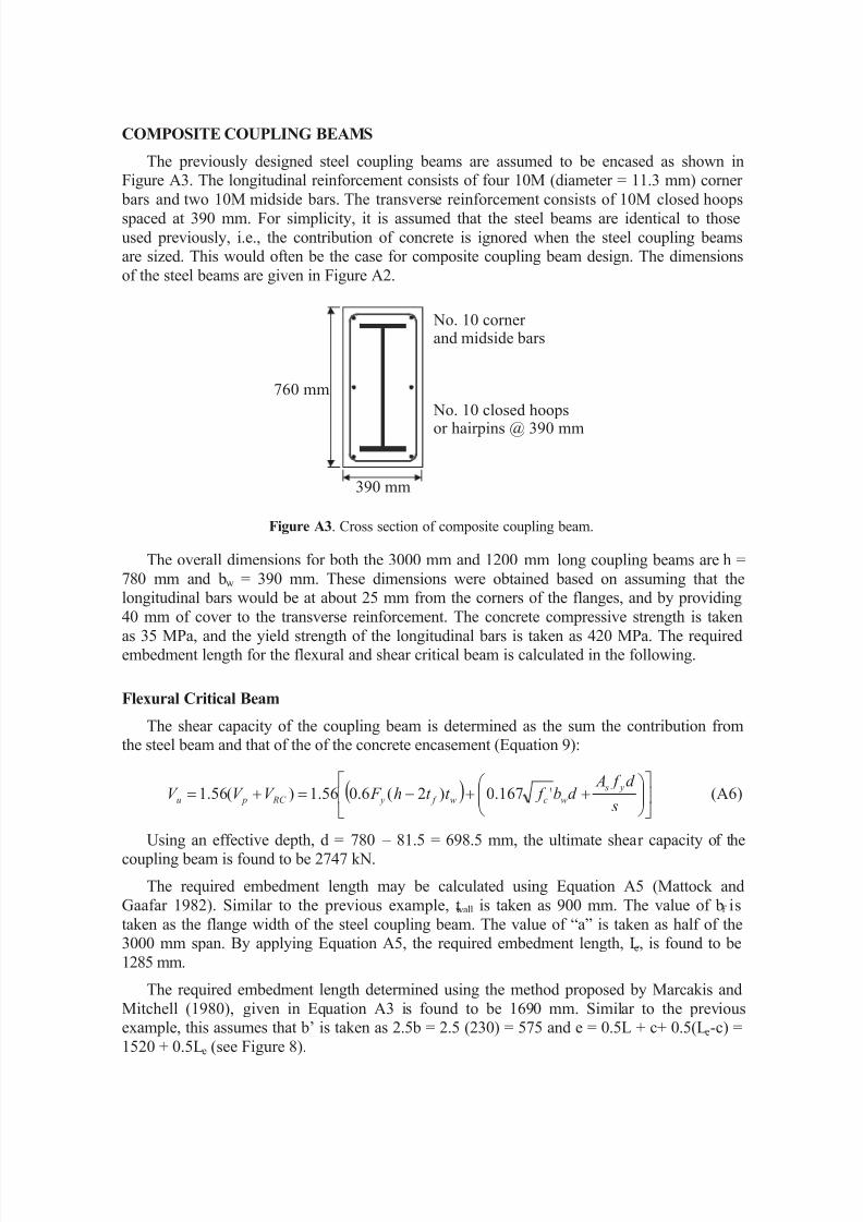
The previously designed steel coupling beams are assumed to be encased as shown inFigure A3. The longitudinal reinforcement consists of four 10M (diameter = 11.3 mm) corner
bars and two 10M midside bars. The transverse reinforcement consists of 10M closed hoops
spaced at 390 mm. For simplicity, it is assumed that the steel beams are identical to those
used previously, i.e., the contribution of concrete is ignored when the steel coupling beamsare sized. This would often be the case for composite coupling beam design. The dimensions
of the steel beams are given in Figure A2.
Figure A3. Cross section of composite coupling beam.
The overall dimensions for both the 3000 mm and 1200 mm long coupling beams are h =
780 mm and bw = 390 mm. These dimensions were obtained based on assuming that thelongitudinal bars would be at about 25 mm from the corners of the flanges, and by providing
40 mm of cover to the transverse reinforcement. The concrete compressive strength is taken
as 35 MPa, and the yield strength of the longitudinal bars is taken as 420 MPa. The requiredembedment length for the flexural and shear critical beam is calculated in the following.
Flexural Critical Beam
The shear capacity of the coupling beam is determined as the sum the contribution fromthe steel beam and that of the of the concrete encasement (Equation 9):
( ) úû
ùêë
é÷÷ ø
öççè
æ ++-=+=
s
d f Ad b f t t h F V V V
y s
wcw f y RC pu '167.0)2(6.056.1)(56.1 (A6)
Using an effective depth, d = 780 – 81.5 = 698.5 mm, the ultimate shear capacity of thecoupling beam is found to be 2747 kN.
The required embedment length may be calculated using Equation A5 (Mattock and
Gaafar 1982). Similar to the previous example, twall is taken as 900 mm. The value of bf is
taken as the flange width of the steel coupling beam. The value of “a” is taken as half of the3000 mm span. By applying Equation A5, the required embedment length, Le, is found to be
1285 mm.
The required embedment length determined using the method proposed by Marcakis and
Mitchell (1980), given in Equation A3 is found to be 1690 mm. Similar to the previousexample, this assumes that b’ is taken as 2.5b = 2.5 (230) = 575 and e = 0.5L + c+ 0.5(L e-c) =
1520 + 0.5Le (see Figure 8).
760 mm
No. 10 corner and midside bars
No. 10 closed hoopsor hairpins @ 390 mm
390 mm

8/14/2019 Behavior and Design of Reinforced Concrete.pdf
http://slidepdf.com/reader/full/behavior-and-design-of-reinforced-concretepdf 23/27
It is suggested that since the beam is “flexure critical” the value of V p may be replaced
with the value of the shear required to achieve the ultimate flexural capacity of the beam,
shown above to be equal to 1.35 x 2Mr /Lfs = 1.35 x 727 / 0.9 = 1090 kN. In this case, therequired shear capacity of the embedment becomes:
÷÷ ø
öççè
æ ++=+=
s
d f Ad b f
L
M V
L
M V
y s
wcr
RC
s
r u '167.056.1
25.156.1
235.1
φ (A7)
For the “flexure critical” beam designed above, the required shear capacity of theembedment region is Vu = 1090 + 1.56(420) = 1745 kN. The require embedment length is
found to be 970 mm (Equation A5) or 1280 mm (Equation A3).
Shear Critical Beam
For the “shear critical” beam, the method is identical to that used for the “flexural
critical” composite beam although only Equation A6 is considered. The design shear forcefor the embedment, Vu is 2,026 kN. Based on Mattock and Gaafar’s model (Equation A5),setting twall = 500 mm, the necessary embedment length is 1025 mm. When using the model
proposed by Marcakis and Mitchell (Equation A3), the value of b’ is approximately 400 mm,
limited by the width of the confining steel (see Figure 8b), and e = 620 + 0.5Le. Based on thismethod, the value of Le is 1350 mm.
The preceding calculations demonstrate the effect of including the capacity of the
concrete encasement. Although the embedments are longer, it has been shown that encased
steel coupling beams do not require the significant stiffener details (see Figure A2) in orderto ensure adequate ductility and stability.
DESIGN OF WALL PIERS
The design of the wall piers is then carried out for flexure using axial loads resulting fromfull plastification of all coupling beams. Figure 6 gives some indication as to the resulting
boundary element reinforcement required for these prototype structures.
ACKNOWLEDGEMENTS
The authors would like to gratefully acknowledge the input and support of members of
American Concrete Institute (ACI) Committee 335 – Composite and Hybrid Structures andProfessor Denis Mitchell of McGill University. The design methods and recommendations
are based on several projects funded by the U.S. National Science Foundation (Grants No.
BCS-8922777 and BCS-9319838 with Dr. Shih Chi Liu as the program director) and the
Natural Science and Engineering Research Council of Canada. Any opinions, findings, andconclusions or recommendations expressed in this paper are those of the authors and do not
necessarily reflect the views of the sponsors.
NOTATION
a = shear span of coupling beam, typically taken as L/2
A = cross sectional area of wall pier
As = area of transverse reinforcement in concrete encasementAsc = area of concentrated reinforcement in boundary element of wall pier
Avd = area of reinforcement in each group of diagonal bars
8/14/2019 Behavior and Design of Reinforced Concrete.pdf
http://slidepdf.com/reader/full/behavior-and-design-of-reinforced-concretepdf 24/27
Aw = area of web of steel beam
b'
= effective width of the concrete compression block bf = coupling beam flange width, also the bearing width of the embedment
bw = web width of concrete beam or concrete encasement
c = depth of concrete cover Cd = deflection amplification factor defined by NEHRP (BSSC 1997)
Cf = resultant bearing (compressive) force in embedment
d = distance from the extreme compression fiber to centroid of longitudinal tensionreinforcement in concrete section
e = eccentricity from midspan of beam to center of embedment
E = Young’s modulus of coupling beam or wall pier f c’ = specified concrete compressive strength
f y = yield strength of reinforcing steel
Fy = yield strength of steel beam
G = shear modulus
h = overall depth of coupling beamI = moment of inertia of coupling beam or wall pier
k = stiffness factor accounting for shear deformations in flexural membersL = effective length of coupling beam
Lclear = length of coupling beam measured from face of wall piers
Le = embedment length of the steel coupling beams inside the wall piersLwall = distance between centroidal axes of the wall piers
Mr = moment capacity of steel beam
s = spacing of transverse reinforcementtf = flange thickness of steel beam
tw = web thickness of steel beam
twall = thickness of wall pier v = shear stressvu = factored shear stress
Vc = factored shear force resisted by concrete
Vn = nominal shear capacity of coupling beamV p = plastic shear capacity of coupling beam
Vr = factored shear capacity of coupling beam
VRC = shear force resisted by reinforced concrete encasementVu = factored shear force on section
x b = length of compression block at back of embedment
xf = length of compression block at front of embedment
a = angle of inclination between diagonal reinforcement and longitudinal reinforcementac = coefficient defining relative contribution of concrete strength to wall strength
b or b1= ratio of the average concrete compressive strength to the maximum stress
g p = shear angle
l = shape factor
q p = plastic interstory drift angle
qe = elastic interstory drift angle computed under code level lateral loads
rn = ratio of area of distributed reinforcement parallel to plane of shear resistance to the
concrete area perpendicular to that plane
fc = material resistance factor for concrete = 0.60
fs = strength reduction factor for steel = 0.90
8/14/2019 Behavior and Design of Reinforced Concrete.pdf
http://slidepdf.com/reader/full/behavior-and-design-of-reinforced-concretepdf 25/27
REFERENCES CITED
American Concrete Institute (ACI) Committee 318, 1995, Building Code Requirements for
Reinforced Concrete and Commentary (ACI 318-95/ACI 318R-95), Farmington Hills, MI, 353 pp.
American Concrete Institute (ACI) Committee 318, 1999, Building Code Requirements for
Reinforced Concrete and Commentary (ACI 318-99/ACI 318R-99), Farmington Hills, MI.
American Institute of Steel Construction (AISC), 1995, Manual of Steel Construction, Load and
Resistance Factor Design, Chicago, IL.
American Institute of Steel Construction (AISC), 1997, Seismic Provisions for Structural Steel
Buildings, Chicago, IL.
Aktan, A. E. and Bertero, V. V., 1981, The seismic resistant design of R/C coupled structural walls,
Report No. UCB/EERC-81/07 , Earthquake Engineering Research Center, University of
California, Berkeley.
Aktan, A. E. and Bertero, V. V., 1984, Seismic response of R/C frame-wall structures, ASCE Journal
of the Structural Division, 110 (ST 8), 1803-1821.
Aktan, A. E. and Bertero, V. V., 1987, Evaluation of seismic response of RC building loaded to
failure, ASCE Journal of the Structural Division, 113 (ST 5), 1092- 1108.
Aristizabal-Ochoa, J. D., 1982, Dynamic response of coupled wall systems, ASCE Journal of the
Structural Division, 108 (ST 8), 1846-1857.
Aristizabal-Ochoa, J. D., 1987, Seismic behavior of slender coupled wall systems, ASCE Journal of
the Structural Division, 113 (ST 10), 2221-2234.
Barney, G. B. et al., 1978, Earthquake Resistant Structural Walls - Test of Coupling Beams, Report to
NSF, submitted by Portland Cement Association, Research and Development, Skokie, IL.
Bertero, V. V., 1980, Seismic behavior of R/C structural walls, Proceedings of the Seventh World
Conference of Earthquake Engineering , Istanbul, Turkey, 1980.
Bertero, V. V., et al., 1974, Hysteretic behavior of reinforced concrete flexural members with webreinforcement, Report No. UCB/EERC 74-9, Earthquake Engineering Research Center,
University of California, Berkeley.
Building Seismic Safety Council (BSSC) 1998, NEHRP Recommended Provisions for Seismic
Regulations for New Buildings and Other Structures (FEMA 302) and Commentary (FEMA 303),
1997 edition, Washington, DC.
Canadian Standards Association (CSA), 1994, CSA A23.3-94 Design of Concrete Structures, Rexdale,
Canada.
Fintel, M. and Ghosh, S. K., 1982, Case study of aseismic design of a 16-story coupled wall using
inelastic dynamic analysis, ACI Journal , 79 (3), 171-179.
Gong B., Shahrooz B. M., 1998, Seismic behavior and design of composite coupled wall systems,
Report No. UC-CII 98/01, Cincinnati Infrastructure Institute, Cincinnati, OH.
Gong B. Shahrooz B. M., and Gillum A. J., 1997, Seismic behavior and design of composite coupling
beams, Composite Construction in Steel and Concrete III , ASCE, New York, 258-271.
Gong B., Shahrooz B. M., and Gillum A. J., 1998, Cyclic response of composite coupling beams, ACI
Special Publication 174 – Hybrid and Composite Structures, Farmington Hills, MI, 89-112.
Harries, K. A., 1995, Seismic Design and Retrofit of Coupled Walls Using Structural Steel , Ph.D.
Thesis, McGill University, 229 pp.
Harries, K. A., 1996, Design and analysis of four prototype eighteen storey coupled wall structures,
McGill University Department of Civil Engineering and Applied Mechanics Structural
Engineering Series Report No. 96-01, 122 pp.
8/14/2019 Behavior and Design of Reinforced Concrete.pdf
http://slidepdf.com/reader/full/behavior-and-design-of-reinforced-concretepdf 26/27
Harries, K. A., 1998, Ductility and deformability of coupling beams in reinforced concrete coupled
walls, Proceedings of the Eighth Canadian Conference on Earthquake Engineering , Vancouver,
June 1999, 475-481.
Harries, K. A., Mitchell, D., Redwood, R. G. and Cook, W. D., 1997, Seismic design of coupling
beams - A case for mixed construction, Canadian Journal of Civil Engineering , 24(3), 448-459.Harries, K. A., Mitchell, D., Redwood, R. G. and Cook, W. D., 1998, Seismic design and analysis of
prototype coupled wall structures, Canadian Journal of Civil Engineering , 25 (5), 808-818.
International Council of Building Officials (ICBO), 1994, Uniform Building Code, Volume 2,
Structural Engineering Design Provisions, Whitier, CA.
Kabeyasawa T., Shiohara H., Otani S., and Aoyama H., 1983, Analysis of the full-scale seven-story
reinforced concrete test structure, Journal of the Faculty of Engineering , University of Tokyo,
XXXVII (2), 431-478.
Kunnath, S. K. and Reinhorn, A. M., 1994, IDARC-2D Version 3.1: Inelastic Damage Analysis of
Reinforced Concrete Building Structures, State University of New York at Buffalo.
Lybas, J. M. and Sozen, M. A., 1977, Effect of beam strength and stiffness on dynamic behavior of
reinforced concrete walls, SRS No. 444, University of Illinois, Urbana-Champaign.Mahin, S. A. and Bertero, V. V., 1975, An evaluation of some methods for predicting seismic
behavior of reinforced concrete buildings, Report No. UCB/EERC 75-15, Earthquake Engineering
Research Center, University of California, Berkeley.
Marcakis K. and Mitchell D., 1980, Precast concrete connections with embedded steel members.
Prestressed Concrete Institute Journal , 25 (4), 88-116.
Mattock A. H. and Gaafar G. H., 1982, Strength of embedded steel sections as brackets. ACI Journal ,
79 (2).
Milev J. I. and Kabeyasawa T., 1996, Modeling of reinforced concrete shear walls in RC frame-wall
structures, personal communication, Tokyo.
New Zealand Standards Association (NZS), 1995, NZS 3101:1995 Concrete Structures Standard .
Paparoni, M., 1972, Model studies of coupling beams, Proceedings of the International Conference
on Tall Concrete and Masonry Buildings, 3, 671-681.
Park, R. and Paulay, T., 1975 Reinforced Concrete Structures, John Wiley and Sons, Inc., New York.
Paulay, T., 1971, Coupling beams of reinforced concrete shear walls, ASCE Journal of the Structural
Division, 97 (ST 3), 843-862.
Paulay, T., 1977, Coupling beams of reinforced concrete shear walls, Proceeding of a Workshop on
Earthquake-Resistant Reinforced Concrete Building Construction, University of California,
Berkeley, July 11-15, 1977, 1452-1462.
Paulay, T., 1980, Earthquake resisting shear walls - New Zealand design trends, ACI Journal , 77 (3),
144-152.
Paulay, T., 1986, The design of ductile reinforced concrete structural walls for earthquake resistance,
Earthquake Spectra, 2 (4), 783-823.
Paulay, T. and Binney, J. R., 1974, Diagonally reinforced concrete beams for shear walls, ACI Special
Publication SP 42 - Shear in Reinforced Concrete, 579-598.
Paulay, T. and Santhakumar, A. R., 1976 Ductile behavior of coupled shear walls, ASCE Journal of
the Structural Division, 102 (ST 1), 93-108.
Paulay, T. and Taylor, R. G., 1981, Slab coupling of earthquake-resisting shear walls, ACI Journal ,
78 (2), 130-140.
Precast/Prestressed Concrete Institute (PCI), 1992, PCI Design Handbook , fourth edition.
Saatcioglu, M., Derecho, A. T. and Corley, W. G., 1987, Parametric study of earthquake-resistant
coupled walls, ASCE Journal of the Structural Division, 113 (1), 141-157.
8/14/2019 Behavior and Design of Reinforced Concrete.pdf
http://slidepdf.com/reader/full/behavior-and-design-of-reinforced-concretepdf 27/27
Scriber, C. F. and Wight, J. K., 1978, Delaying shear strength decay in reinforced concrete flexural
members under large load reversals, Report UMEE 78 R2, Department of Civil Engineering,
University of Michigan.
Shahrooz B. M. and Gong, B., 1998, Steel-concrete coupling beams: a critical overview of design
guidelines, Structural Engineers World Wide 1998, paper T186-3.Shahrooz B. M., Remmetter M. A. and Qin F., 1992, Seismic response of composite coupled walls,
Composite Construction in Steel and Concrete II , ASCE, 429-441.
Shahrooz B. M., Remmetter M. A. and Qin F., 1993, Seismic design and performance of composite
coupled walls, ASCE Journal of the Structural Division, 119 (11), 3291-3309.
Shiu, N. K., Barney, G. B., Fiorato, A. E. and Corley, W. G., 1978, Reversed load tests of reinforced
concrete coupling beams, Proceedings of the Central American Conference on Earthquake
Engineering , El Salvador, 239-249.
Shiu, N. K., Barney, G. B., Fiorato, A. E. and Corley, W. G., 1981, Earthquake Resistant Walls -
Coupled Wall Test , Report to NSF submitted by Portland Cement Association, Research and
Development, Skokie, Illinois.
Shiu, N. K., Takayangi, T. and Corley, W.G., 1984, Seismic behavior of coupled wall systems, ASCE Journal of the Structural Division, 110 (ST 5), 1051-1066.
Stafford-Smith, B. and Coull, A., 1991, Tall Building Structures, Wiley Interscience.
Tassios, T. P., Moretti, M., and Bezas, A., 1996, On the coupling behavior and ductility of reinforced
concrete coupling beams of shear walls, ACI Structural Journal 93 (6), 711-720.
Teshigawara M., Kato M., Sugaya K.I., 1996, Seismic test on 12-story T-shaped coupled shear wall,
Proceedings of the Third Joint Technical Coordinating Committee Meeting , Hong Kong,
December 12-14, 1996.
Tunc G., Deason J., and Shahrooz B. M., 2000, Seismic response of R.C. core wall-steel frame hybrid
structures, Report No. UC-CII 00/01, Cincinnati Infrastructure Institute, Cincinnati, OH.
Vulcano A. and Bertero V. V., 1987, Analytical models for predicting the lateral response of RC
shear walls, Report No. UCB/EERC-87/19, Earthquake Engineering Research Center, Universityof California, Berkeley.