Embed Size (px)
Citation preview
15th International Brick and Block
Masonry Conference
Florianópolis – Brazil – 2012
REINFORCED MASONRY IN EUROPE – STATE OF THE ART:
MASONRY UNDER COMPRESSION AND SHEAR
Kubica, Jan1; Mojsilović, Nebojša
2
1 PhD, DSc, Professor, Silesian University of Technology, Dept of Structural Engineering, [email protected]
2 PhD, Senior Scientist, Institute of Structural Engineering, ETH Zurich, [email protected]
The behaviour of reinforced masonry structures, especially where reinforcement is provided
to enhance the strength or resistance of the masonry is still not completely investigated. The
first task of the recently set Working Group (WG5) – Reinforced and Prestressed Masonry
(of CIB W023 Commission) is to produce a State of the Art document covering reinforced
masonry applications, mainly in Europe, in order to identify the topics for future research and
development. Based on the available test results, the behaviour of reinforced masonry
structures is discussed in the present paper. Masonry structures reinforced with bed joint
reinforcement only and with both bed joint and vertical reinforcement and subjected to
vertical and shear loading are investigated. Finally, the design of reinforced masonry
according to Eurocode 6 (EN 1996) and other regulations and national standards is discussed.
Keywords: Load test; reinforced masonry; standards; state-of-the art; structural behaviour.
INTRODUCTION
The behaviour of reinforced masonry structures, especially where reinforcement is provided
to enhance the strength or resistance of the masonry is still not completely investigated.
Recently, the Commission W023 – Wall Structures of the International Council for Building
Research Studies and Documentation (CIB) set up a Working Group (WG5) – Reinforced and
Prestressed Masonry, which of the authors are convenors. The first task of the WG5 is to
produce a State of the Art document covering reinforced masonry applications, especially in
Europe, in order to identify the topics for future research and development. This process is
now underway and this paper presents the work done so far.
Firstly, a description of reinforcing steel used in masonry structures is given. Different types
of steel reinforcement are presented and relevant standardisation is discussed. Note that this
paper does not deal with the usage of non-metallic (bed joint) reinforcement. Secondly, based
on the test results, the behaviour of reinforced masonry structures is discussed. The influence
of two different types of reinforcement on the structural behaviour is investigated: masonry
structures reinforced with bed joint reinforcement (consistent with EN 845-3:2003) only and
with both the bed joint and vertical reinforcement. Due to the limited paper volume, the
loading types considered here comprise vertical and shear loading. Furthermore, only the
static loading is investigated. Finally, the design of reinforced masonry according to different
regulations and national standards is discussed, with the emphasis on the provisions of the
European Structural Masonry Code, EN 1996. A set of conclusions together with pertinent
recommendations for future actions closes the paper.
15th International Brick and Block
Masonry Conference
Florianópolis – Brazil – 2012
REINFORCEMENT TYPES USED IN MASONRY
Generally, in European countries several different types of steel reinforcement for masonry
structures (placed into the bed joints or in vertical voids or pockets) are in use:
steel wires – with diameter from = 3 mm to = 6 mm;
steel reinforcing bars (smooth or rebar) with diameter = 4.5 mm to = 8 mm
(usually placed in the bed joints) and = 8 mm to = 36 mm (used mainly as vertical
reinforcement placed in vertical voids of masonry or in concrete sections of mixed
masonry-concrete structures);
flat steel profiles (used as reinforcement for masonry lintels).
The European standard EN 845-3:2003 specifies requirements for steel reinforcement,
especially bed joint reinforcement, intended for use in masonry structures. According to this
code there are four types of prefabricated bed joint reinforcement: truss type, ladder type,
woven wire meshwork and expanded metal meshwork.
The European Structural Masonry Code EN 1996-1-1:2005 specifies that prefabricated bed
joint reinforcement shall be in accordance with EN 845-3:2003 and protected according to
requirements specified in EN 1996-2:2006.
MASONRY WALLS AND COLUMNS SUBJECTED TO COMPRESSION
In Europe, especially in West European countries, the bed joint reinforcement application for
masonry load-bearing structures mainly subjected to vertical compressive loads (walls and
columns) is very limited in design practice. In addition, this topic was not investigated
experimentally extensively. Several research projects dealt with this topic, though: in
Germany by Ohler & Göpfert (1982), Haardt & Hilsdorf (1991), Floher & Hilsdorf, (1980,
1982) and Ernst (1995), as well as in Greece by Vintzileou (1999).
At the University of Kaiserslautern Ohler & Göpfert (1982) investigated compressed masonry
columns with rectangular cross-section 240 mm 240 mm and a height of 1750 mm, which
were reinforced in each bed joint with three different types of bed joint reinforcement:
rectangular stirrups (wires with a diameter = 3 mm), circular stirrups (wires with a diameter
= 6 mm) and rectangular mesh (opening dimensions 75 mm 75 mm). The positive effect
of reinforcement on load-bearing capacity was observed for specimens reinforced with mesh
and circular stirrups. The ultimate load could be increased between 13% and 24% depending
on the type of the masonry units used. Specimens reinforced with rectangular stirrups had not
shown an increase of load bearing capacity of the columns.
Haardt & Hilsdorf (1991) tested also masonry columns reinforced with steel meshes in bed
joints and built of hollow clay blocks, calcium-silicate blocks and light aggregate concrete
blocks. Two types of steel reinforcing meshes were used with a reinforcement ratio of
= 0.05%. Test specimens had rectangular cross-section 240 mm 240 mm, were 1140 mm
high and were compressed eccentrically or centrically by an axial load. In all tests an increase
of the ultimate load was observed. Reinforced specimens had an increase in load-bearing
capacity of ca. 30% to 47% (depending on the type of masonry units and load eccentricity)
compared to the unreinforced elements. Somewhat different results were obtained from tests
on the compressed masonry columns presented in Vintzileou (1999). Four specimens built of
hollow clay bricks and cement-lime mortar with cross-section dimensions 490 mm 320 mm
and a height of 1050 mm were reinforced with steel meshes ( = 5 mm diameter and opening
dimensions 100 mm 100 mm) in bed joints. All reinforced specimens showed a decrease in
15th International Brick and Block
Masonry Conference
Florianópolis – Brazil – 2012
load-bearing capacity compared to the unreinforced ones. It seems that the reinforcement ratio
was too low to produce a positive effect.
Investigations on masonry walls with different types of bed joint reinforcement were carried
out by Floher & Hilsdorf (1980, 1982) at Karlsruhe University. Six types of masonry units
and 8 types of bed joint reinforcement were tested. The main test parameters included
reinforcement diameters, which ranged from 0,55 mm to 5 mm, and mesh opening
dimensions, which ranged from 5 mm 5 mm to 50 mm 50 mm. Also, in some tests a glass
fibres reinforcement and truss type prefabricated bed joint reinforcement were applied.
Summing up the test results it can be said that, the influence of truss type prefabricated
reinforcement (for reinforcement ratio = 0.05%) on load-bearing capacity was not observed.
Better results were obtained for all types of mesh type reinforcement. It was possible to
increase the load-bearing capacity for 2% to 20% (for the same reinforcement ratio).
Ernst (1995) performed tests on 13 masonry wall specimens built of hollow clay blocks in
Darmstadt: 5 of them were unreinforced, 3 with grout-filled vertical voids, 3 with bed joint
reinforcement and 2 with bed joint and vertical reinforcement. All specimens had same shape
and were 560 mm long, 300 mm wide and 985 mm high. Masonry walls with filled vertical
voids had 15%-20% greater load-bearing capacity than unreinforced walls. Bed joint
reinforcement application resulted in a similar capacity enhancement, whereas introduction of
additional vertical reinforcement resulted in ca. 50% increase of ultimate load.
Further research was performed at the Department of Building Structures of the Silesian
University of Technology by Drobiec et al. (2002). Within this project the influence of
different types and reinforcement ratios of bed joint reinforcement on the behaviour and
failure mode of in-plane loaded masonry walls was investigated. All tested specimens
(masonry wallettes) were built using solid clay bricks and cement-lime mortar and had a
rectangular shape with dimensions 1415 mm 1290 mm and were 250 mm thick. Five
different types of the bed joint reinforcement were tested: two unconnected longitudinal bars
with diameter 6 mm, two unconnected longitudinal spiral rods with diameter 6 mm, woven
mesh with diameter 4 mm and opening size of 4040 mm, welded mesh with diameter 1.2
mm and opening size of 12 12 mm and finally truss type prefabricated bed joint
reinforcement with bar diameter of 5 mm. Furthermore, two different reinforcement ratios
were investigated, = 0.05% and = 0.1%. As a reference, a series of unreinforced
specimens were also tested. At the cracking load, as well as at the failure the application of
two unconnected reinforcing bars showed, especially for reinforcement ratio = 0.1%, an
unsatisfactory performance. Much better results were observed in the case of mesh type
reinforcement and prefabricated truss type bed joint reinforcement which influenced
positively both structural behaviour and ultimate resistance of specimens, especially for
welded and woven meshes. In case of specimens reinforced by meshes the load capacity was
ca. 25% and ca. 40% higher than for unreinforced elements. For the specimens with
prefabricated truss type reinforcement, for reinforcement ratio of 0.05%, load capacity was
practically same as for unreinforced walls, but for = 0.1% it was 25% higher. No
differences between failure modes of unreinforced specimens and those reinforced with mesh
and truss type prefabricated reinforcement were observed. However, the failure mode of
specimens reinforced by two unconnected longitudinal steel bars was different – at failure,
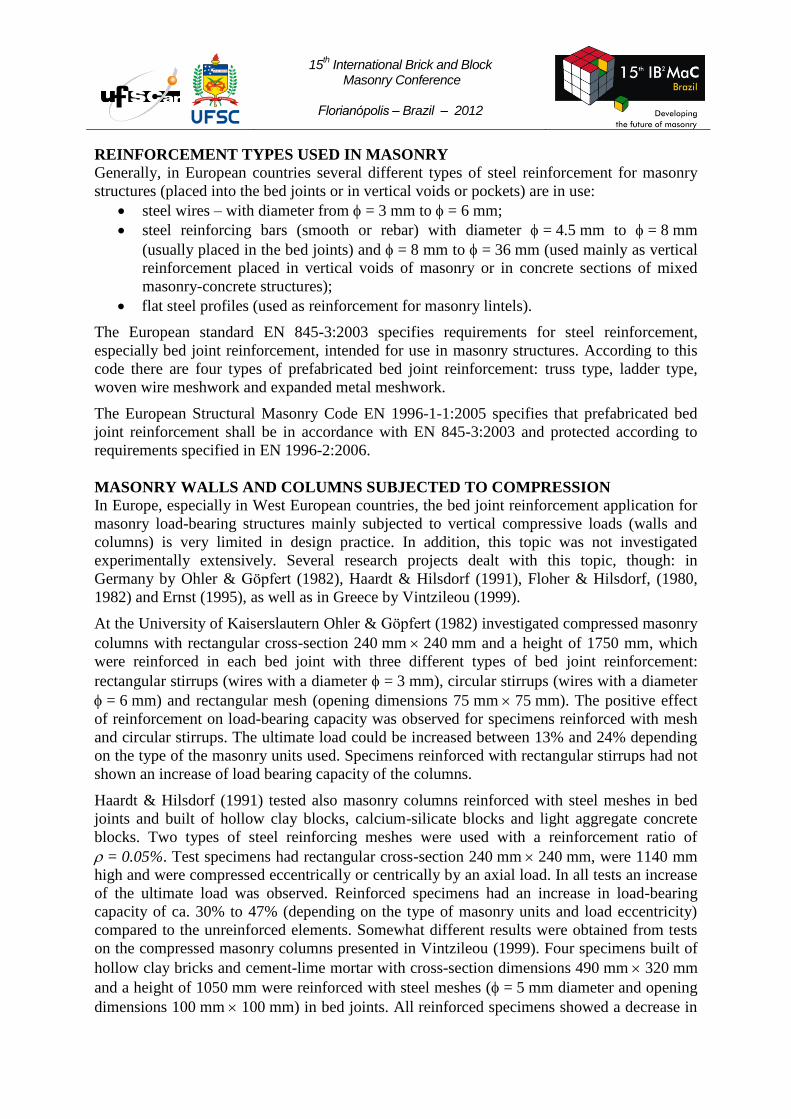
walls were vertically separated into two parts (see Figure 1).
15th International Brick and Block
Masonry Conference
Florianópolis – Brazil – 2012
a)
b)
c)
Figure 1: Failure of unreinforced masonry wallettes by internal longitudinal crack:
a) scheme of the crack pattern; b) failure of masonry wallette half brick thick;
c) failure of masonry wallette brick length thick
Design Method – masonry columns
West European national masonry standards (including EN 1996) do not contain a design rules
for reinforced masonry columns and walls under compression, especially for those reinforced
with bed joint reinforcement. On the other hand, most of the former national standards in
Central and East European countries, as well as Russian Code SNiP II-22-81 (2000) and
Chinese GBJ3-88 (1998) incorporated the design procedures for such reinforced masonry
structures, see also Dajun (1997). These design procedures have been thoroughly discussed in
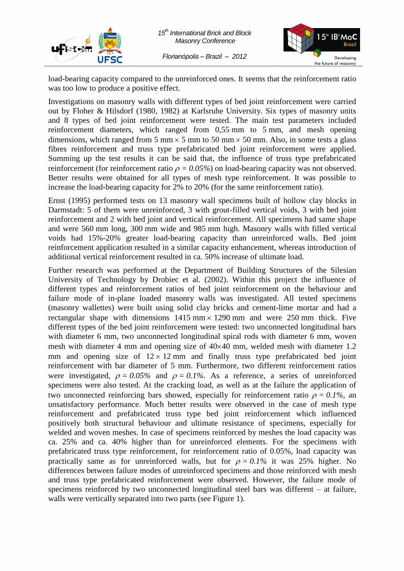
Drobiec & Kubica (2008). The load capacity of axially compressed masonry columns with
bed joint reinforcement as shown in Figure 2, fdr, (made of masonry units group 1 – according
to EN 1996-1-1:2005 classification) can be calculated as, fd being the design value of
compressive strength of masonry:
dydmddrf
y
efρff 2212
(1)
where: m – volume reinforcement ratio,
;
21
21
saa
aaAρ
sa
m
Asa – cross-sectional area of one wire of mesh or loop;
a1, a2 – dimensions of mesh openings or loops; measured as in Figure 2;
s – vertical spacing between reinforced bed joints (Figure 2a); distance
between bed joints with this same direction of the reinforcement in the
case of loop type reinforcement (Figure 2b);
e – design value of total eccentricity;
y – distance between centre of area of masonry cross-section and more
compressed edge of the section.
Formula (1) can be used for the design of masonry columns of square cross-section (when
t = b). For columns with rectangular cross-section (t b), equation (1) has modified form:
dydmddr aabt
atabf
y
efρff 2212
21
12
(2)
15th International Brick and Block
Masonry Conference
Florianópolis – Brazil – 2012
where is the Poisson’s ratio for masonry (usually taken as = 0,25); dimensions t and b – as
shown in Figure 2. Equation (2) should be used only for masonry columns whose cross-
section dimensions fulfil the relationship: 0,5 ≤ b/t ≤ 2. Moreover, the vertical spacing s
between bed joints covering reinforcement should not exceed 500 mm and s ≤ min (t;b).
a)
b)
Figure 2: Masonry columns with bed joint reinforcement (acc. to Polish Masonry Code
PN-B-03002:2007): a) mesh type reinforcement; b) loop type reinforcement
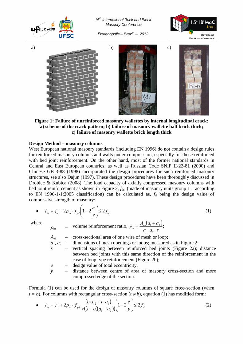
Figure 3 shows the ratios fdr/fd, with fdr calculated from (1) or (2) and fd obtained from test
data, for different values of reinforcement ratio. It is clear from the figure that calculated
values of fdr are on the safe side, for some tests even too conservative.
Figure 3: The fdr/fd ratio for different reinforcement ratios
Proposed Design Method – masonry walls
Using the above-mentioned and discussed formulae (1) and (2) for determination of the
compressive strength fdr of masonry walls with bed joint reinforcement (i.e. when length of
the masonry structural element b exceeds 1.0 m or the 0,5 ≤ b/t ≤ 2 relationship is not
fulfilled) is not correct. In such cases, different types of the bed joint reinforcement
(compared to those shown in Figure 2) are used. According to requirements specified in EN
1996-2:2006 and EN 845-3:2003, in the case of masonry walls prefabricated steel bed joint
fdr/fd
15th International Brick and Block
Masonry Conference
Florianópolis – Brazil – 2012
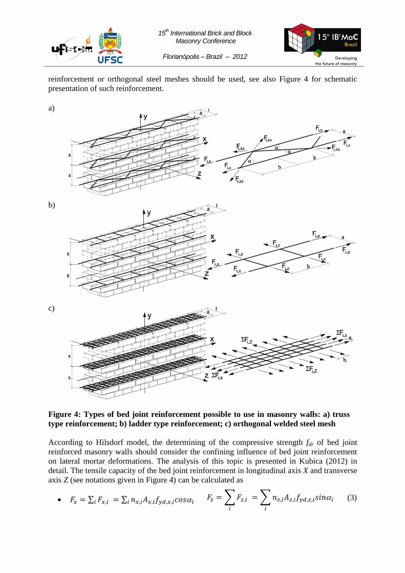
reinforcement or orthogonal steel meshes should be used, see also Figure 4 for schematic
presentation of such reinforcement.
a)
b)
c)
Figure 4: Types of bed joint reinforcement possible to use in masonry walls: a) truss
type reinforcement; b) ladder type reinforcement; c) orthogonal welded steel mesh
According to Hilsdorf model, the determining of the compressive strength fdr of bed joint
reinforced masonry walls should consider the confining influence of bed joint reinforcement
on lateral mortar deformations. The analysis of this topic is presented in Kubica (2012) in
detail. The tensile capacity of the bed joint reinforcement in longitudinal axis X and transverse
axis Z (see notations given in Figure 4) can be calculated as
(3)
15th International Brick and Block
Masonry Conference
Florianópolis – Brazil – 2012
where: nx,i and nz,i – number of bars in corresponding axis direction; Ax,i and Az,i – cross-
section area of single reinforcing bar; fyd,x,i and fyd,z,i – yield strength of reinforcing bars steel;
i – the angle between reinforcing bar axis and longitudinal axis of the wall (X axis).
Based on the analytical analysis carried out in accordance with earlier presented, for masonry
columns, the fdr strength may be determined as the sum of compressive strength of
unreinforced masonry fd and lesser value (min (y,z;y,z)) of reinforcement capacity in
directions of X and Z axis:
(4)
where E is the elastic orthotropy coefficient, calculated as
and is the mean value
of Poisson’s ratio for unreinforced masonry. This formula was compared with results of test
carried out in Poland by Drobiec (2002), see Kubica (2012) for more details. Generally, the
relationship (3) for determining of fdr may be used only for masonry walls with orthogonal
bed joint reinforcement – like prefabricated ladder type reinforcement (see Figure 4b) or steel
welded mesh presented in Figure 4c. In the case of the walls with prefabricated steel truss
type bed joint reinforcement (like the one shown in Figure 4a) somewhat different results
have been found. Values of fdr calculated using formula (3) were significantly lower than
those obtained from tests. The confining influence of the strong longitudinal bars is enhancing
the reinforcement capacity also in direction perpendicular to the wall. As the result, the
limitation of tensile strains in zigzag connecting bars is observed. Such phenomenon may be
taking into consideration by introducing reinforcement confining factor xz determined from
the total reinforcement capacity for both directions (X and Z) and reinforcing wires capacity in
direction of Z axis:
(5)
where a is the distance between both longitudinal bars and b is the length of the projection of
the zigzag wire between welding points on longitudinal axis X, see Figure 4a. Modified
formula for fdr strength determination in the case of using truss type bed joint reinforcement
can be expressed as follows:
(6)
and fits well, see also Kubica (2012), to results from tests carried out by Drobiec (2002) for
masonry walls made of clay solid bricks and cement-lime mortar when reinforcing percentage
0,05% and 0,1%.
MASONRY WALLS SUBJECTED TO SHEAR
Walls Subjected to Horizontal Shear Force
One of the first and well documented experimental investigations on reinforced shear
masonry walls with horizontal and mixed horizontal and vertical reinforcement was carried
out in USA by Scrivener (1969). The test program covered 12 masonry specimens built of
hollow concrete blocks. All specimens had the same dimensions and were 2400 mm long and
15th International Brick and Block
Masonry Conference
Florianópolis – Brazil – 2012
2600 mm high and were subjected to diagonal shearing. Reinforcement enhanced the
structural behaviour of walls significantly. For example for the walls with reinforcement only
in bed joints an increase in load bearing capacity of 70% was observed.
Ančić & Steinman (1984) carried out tests on masonry walls reinforced in bed joint and
subjected to a horizontal load. Total of 46 masonry walls were tested according to RILEM
LUMB 6 recommendations. 17 walls were built with solid clay bricks and had dimensions of
1050 mm 1050 mm 125 mm and were reinforced using two reinforcement ratios
= 0.15% and = 0.27%. Additional 29 walls were built with hollow clay blocks and had
dimensions of 1050 mm 1050 mm 190 mm and were reinforced using reinforcement
ratios which ranged from = 0.11% to = 0.30%. For solid clay bricks masonry walls a
positive influence of bed joint reinforcement on load capacity was observed for both
reinforcement ratios. Different results were observed for hollow clay blocks masonry. The
enhancement in load capacity was observed for reinforcement ratios higher than = 0.17%.
Sanpaelsi & Cieni (1984) tested solid clay bricks masonry walls which had bed joint
reinforcement in form of two longitudinal bars with diameter = 4 mm Wall dimensions were
1000 mm 1000 mm 125 mm and the walls were subjected to compression force along the
specimen’s diagonal. The increase of the ultimate shear stresses of reinforced specimens
compared to unreinforced ones was about 5% for reinforcement ratio = 0.19%.
The investigations presented above treated masonry wall specimens subjected to shear in
typical diagonal tests (compression along diagonal axis). Somewhat different approach was
chosen in large-scale tests carried out in Poland by Jasinski (2002). Masonry walls were
subjected to horizontal (parallel to bed joints) shear – with and without pre-compression.
Total of 51 clay brick masonry wallettes with dimensions 1680 mm 1415 mm 250 mm
(length height thickness) were tested. 11 specimens were unreinforced as reference
members and 40 specimens were reinforced using two types of bed joint reinforcement: truss
type prefabricated reinforcement and two, not connected to each other, longitudinal steel
smooth bars. Two different reinforcement ratios were used, namely = 0.05% and = 0.1%.
Generally, both types of used reinforcement resulted in better behaviour and a higher shear
stresses levels corresponding to first diagonal crack appearance and to failure, especially for
walls subjected to shear without pre-compression and reinforced with prefabricated bed joint
truss type reinforcement, could be reached. Walls with a reinforcement ratio = 0.1%
showed only a slight increase in the above mentioned shear stresses compared to those
reinforced with = 0.05%. Furthermore, the ultimate shear stresses increased with increasing
level of pre-compression. For truss type prefabricated reinforcement, at the failure, for
= 0.1% the ultimate shear stresses were ca. 50% higher than those obtained for unreinforced
walls with a pre-compression of 1.0 N/mm2. For higher levels of pre-compression, i.e.
for 1.5 N/mm2 the application of the truss type reinforcement resulted in an ultimate shear
stress which was higher for about 30%. Failure modes in tests with reinforced specimens were
practically identical with those observed for unreinforced walls and significantly depended on
level of the pre-compression, and not on the type of reinforcement used.
Design Method
According to EN 1996-1-1:2005, for the case of masonry shear walls containing vertical
reinforcement and subjected to horizontal shear, if the horizontal shear reinforcement is
provided, a shear load at ultimate can be calculated as:
15th International Brick and Block
Masonry Conference
Florianópolis – Brazil – 2012
ydswvdRd fAtlfV 9.0 (7)
where: fvd – design shear strength of masonry;
l – length of the wall;
t – thickness of the wall;
Asw – total area of the horizontal shear reinforcement over the part of the wall
being considered;
fyd – design yield strength of the reinforcing steel.
Additionally, the following condition must be satisfied:
2N/mm 0.29.0
tl
fAtlf ydwsvd (8)
For the shear walls not containing vertical reinforcement, the contribution of the bed joint
reinforcement on load-bearing capacity must be neglected.
Internationally, there are some other proposals (Brunner & Shing (1996), Shing et al. (1990))
but a unique design method has not yet been established.
Walls Subjected to Vertical Shear Force
In the case of masonry walls subjected to loads which result in vertical shear (e.g. masonry
shear walls of buildings subjected to irregular foundation settlements) the calculation of
ultimate shear load for reinforced masonry is still not enough investigated, both theoretically
and experimentally. A series of tests were carried out by Cook et al (1995). The 5 m long
portion of clay brick masonry wall spanned between two window openings (with span
1.45 m) was subjected to vertical shear forces. As the first step, the unreinforced wall was
loaded up to the cracking load. Afterwards, the specimen was strengthened either with
= 6 mm longitudinal bars, spiral rods or flat profiles with dimensions 30 mm 5 mm which
were placed into bed joints. After strengthening, the ultimate load reached was ca. 2.5 times
larger than cracking load.
Within two other research projects Drysdale & Hamid (1979) tested small
(803 mm 803 mm) and Mojsilović & Marti (1994) full-scale (1290 mm 1300 mm)
reinforced wall specimens subjected to axial compression in the direction inclined to the bed
joints, thus simulating combined actions. Wall specimens were built with hollow clay blocks
and cement mortar. At an inclination angle of 450 to bed joints, no differences in ultimate
loads between unreinforced and reinforced specimens were observed in both projects. In the
Swiss investigation, on the specimen with an angle of inclination of 300
the ultimate load
could be increased 13% compared to unreinforced one. Moreover, the reinforced specimens
exhibited much better deformation behaviour and were characterised by less brittle failure.
A broader investigation of the behaviour of bed joint reinforced masonry walls were carried
out in Poland by Kubica & Piekarczyk (2004). Masonry walls were subjected to vertical shear
and several different levels of pre-compression. Totally, 40 clay brick masonry wall
specimens (10 unreinforced as reference and 30 with bed joint reinforcement) with
dimensions 1290 mm 1415 mm 250 mm were tested. Two types of bed joint reinforcement
(longitudinal unconnected bars = 6 mm and truss type prefabricated reinforcement with
= 5 mm ) and two reinforcement ratios were used: = 0.05% and = 0.1%. From the test
results a conclusion can be drawn, that for both types of reinforcement a positive influence of
the reinforcement on the structural behaviour and on the both stress levels at crack opening
15th International Brick and Block
Masonry Conference
Florianópolis – Brazil – 2012
and at ultimate could be observed. For all pre-compressed walls the increase in failure load
was larger for reinforcement ratio = 0.1% than for = 0.05%. On the other hand, for the
walls without pre-compression the opposite was observed, i.e. the increase was larger for
smaller value of . The failure modes and crack patterns of all reinforced walls were similar
to those obtained for unreinforced elements (diagonal cracks across whole specimen) and
depended strongly on the levels of pre-compression, and not on the type of the used
reinforcement. For specimens with rather low level of pre-compression (up to 0.6 N/mm2) the
failure manifested through one diagonal crack, whereas for higher levels of pre-compression
several cracks parallel to diagonal were observed. Discussion of these results, from the
designer point of view, was presented in Kubica & Timperman (2004).
Design Method
Unfortunately, up to now there are no reliable design or calculating procedures for reinforced
masonry walls subjected to vertical shear. This is also not handled in the masonry codes
throughout Europe, including EN 1996-1-1:2005. Such procedure need to be developed and
implemented, especially having in mind numerous cases of masonry walls subjected to such
loading (settlement of foundations, spandrel beam elements in masonry frames, etc.).
CONCLUSIONS AND REMARKS
The behaviour of reinforced masonry structures, especially where reinforcement is provided
to enhance the strength or resistance of the masonry is important but not yet sufficiently
investigated. As a consequence, a lack of suitable design procedures in masonry standards is
present. An improvement in this matter is only possible to achieve through thorough and
extensive theoretical and experimental research. At the moment, the knowledge level in the
field of reinforced masonry structures is still rather low, especially in case of reinforcement
placed only in bed joints. Separate group of problems present the usage of non-metallic bed
joint reinforcement – mainly in the shape of orthogonal nets of ladder type reinforcing
components made of glass or carbon fibres. Practically there are no reports on investigation of
the behaviour of such reinforced masonry structures subjected to different types of loading.
From the presented state of the art analysis of reinforced masonry structures (walls and
columns) the following conclusions can be formulated:
Nowadays, there is a clear lack of knowledge and design procedures for reinforced
masonry structures (walls and columns) subjected to compressive and shear loads.
In the case of masonry columns with bed joint reinforcement the load-bearing capacity
can be calculated using formulae (1) or (2). This procedure is being used in many
countries in Central and East Europe, as well as Russia and China, is on the safe side
and verified by numerous tests data.
Masonry walls with bed joint reinforcement may be calculated using proposed method
based on formulae (4) and (6). However, there is a need for additional verification by
test data.
Masonry walls subjected to shear stresses (in both directions) are traditionally
reinforced with disconnected bars, but more effective and safer, especially in case of
horizontal shear, is usage of the prefabricated truss type bed joint reinforcement.
Future research should concentrate on the developing of a reliable design rules and
procedures, which should be backed by experimental investigations and be suitable for use by
practicing engineers.
15th International Brick and Block
Masonry Conference
Florianópolis – Brazil – 2012
REFERENCES
Ančić D., Steinman V. “Tensile strength of masonry walls as a factor of earthquake resistance
of masonry buildings”, Proc. 3rd
International CIB Symposium Wall Structures, Warsaw
1984, Vol. II, pp.253-260.
Brunner J.D., Shing P.B. “Shear strength of reinforced masonry walls”, TMS Journal, Vol.14,
No 1, 1996, pp.65-77.
Cook D., Ring S., Fichtner W. “The effective use of masonry reinforcement for crack repair”,
Proc. 4th
IMC, Proc. No 7, Vol. 2, London 1995, pp.442-450.
Dajun D. “Studies on brick masonry under compression”, Materials and Structures/Matériaux
et Constructions, Vol.30, 1997, pp 247-252.
Drobiec Ł. Kubica J. “Influence of Some Types of Bed Joint Reinforcement on Mechanical
Properties of Masonry Under Compression”, Proc. 6th
IMC, Masonry (9), London 2002,
pp.99-104.
Drobiec L., Kubica J. “Masonry walls and columns with bed joint reinforcement subjected to
vertical loads – proposition of design method”, Proc’ 14th
IB2MaC, Sydney 2008, Book of
abstracts p.79, (paper No 117 on CD).
Drysdale R.G., Hamid A.A., Heidebrecht A.C. “Tensile strength of concrete masonry”,
Journal of the Structural Division, Vol. 105, No 7, 1979, pp.1261-1276.
EN 1996-1-1:2005. Eurocode 6 – Design of masonry structures – Part 1-1: General rules for
reinforced and unreinforced masonry structures.
EN 1996-2:2006. Eurocode 6 – Design of masonry structures – Part 2: Design considerations,
selection of materials and execution of masonry.
EN 845-3:2003 Specification for ancillary components for masonry – Part 3: Bed joint
reinforcement of steel meshwork.
Ernst M. “Tests of reinforced masonry walls subjected to in-plane loading”, Darmstadt
concrete, No 10, 1995, pp.131-143.
Ernst M. “Compressive strength of reinforced perforated clay block masonry”, Darmstadt
concrete, No 10, 1995, pp.145-161.
Flohrer C., Hilsdorf H.K. “Festigkeits- und Verformungsverhalten von faserbewehrtem
Mauerwerk”, Schlussbericht zum Forschungsauftrag BII-800 176 42. Der Bundesminister für
Raumordnung Bauwesen und Städtebau, April 1980.
Flohrer C., Hilsdorf H.K. “Enhanced ductility of masonry loaded in compression”, Proc. 6th
International Brick/Block Masonry Conference, Rome 1982, pp.1129-1141.

15th International Brick and Block
Masonry Conference
Florianópolis – Brazil – 2012
GBJ3-88 Design Code for Masonry Structures (in Chinese), China Building Industry Press,
Beijing, 1988, 69 p.
Haardt P., Hilsdorf H.K. “Tragfähigkeistuntersuchungen an exzentrisch belasteten bewehrten
Mauerpfeilern”, Proc. 9th
International Brick/Block Masonry Conference, Berlin 1991,
pp.421-431.
Jasinski R., Kubica J. “Investigation of the Influence of Bed Joint Reinforcement on the
Strength and Deformation Characteristics of Clay Brick Masonry under Horizontal Shear”,
Proc. 6th
IMC, Masonry (9), London 2002, pp.236-241.
Kubica J. “Masonry walls with bed joint reinforcement – a trial of description of the problem
with first proposition of design method”, Proc. 15th
IBMaC, Florianópolis 2012, ibidem.
Kubica J., Timperman P. “Metselwerk onderhevig aan differentiële zettingen”, Cement, No 5,
2004, pp.72-74.
Kubica J., Piekarczyk A. “Tests of vertically sheared clay brick masonry walls with and
without bed joint reinforcement”, Proc. 13th
IB2MaC, Amsterdam 2004, pp.191-200.
Mojsilović N., Marti P. Versuche an kombiniert beanspruchten Mauerwerkswänden. Institut
für Baustatik und Konstruktion, ETH Zürich, Bericht Nr. 203, Birkhäuser Verlag, 1994.
Ohler A., Göpfert N. “The effect of lateral joint reinforcement on the strength and
deformation of brickwork piers”, Proc. 6th
International Brick/Block Masonry Conference,
Rome 1982, pp.667-687.
PN-B-03002:2007 Design of masonry structures. Calculations and design.
RILEM LUMB 6 Diagonal tensile strength tests of small wall specimens.
Sanpaelsi L., Cieni P. “Experimental analysis of a reinforced masonry typology under static
and cyclic loadings to be used in seismic areas”, Proc. 3rd
International CIB Symposium Wall
Structures, Warsaw 1984, Vol. II, pp.232-330.
Scrivener J.C. “Static racking tests on concrete masonry walls”, International Conference on
Masonry Structural System. Texas, Austin 1969, pp.185-191.
Shing P.B., Schuller M., Hoskere V.S. “In-plane resistance of reinforced masonry walls”,
Journal of Structural Engineering ASCE, Vol.116, No 3, 1990, pp.619-640.
SNiP II-22-81. Czast 2. Gława 2. Kamiennyje i armokamiennyje konstrukcji.
Gossudarstwiennyj Komitet CCCP po Diełam Stroitielstwa, Moskva, 2000.
Vintzileou E. “Improvement of ductility characteristic of plain masonry by means of local
horizontal reinforcement”, Masonry International, vol.13, no 1, 1999, pp.27-31.