Embed Size (px)
Citation preview

143
R E I N F O R C E D M A S O N R Y - S E I S M I C B E H A V I O U R A N D D E S I G N
J. C. Scrivener*
1. INTRODUCTION
It is interesting to recall I. L. Holmes* comment from the Seminar on Seismic Problems in Structural Engineering 1 9 6 8 ( 1 / - "reinforced masonry can be designed by the same rules as reinforced concrete". This is really the theme of this paper. What Holmes said in 1 9 ^ 8 , on scant evidence, has been shown in the testing which has been conducted since then to be completely correct.
We are exceedingly fortunate in New Zealand in that the quality of materials of construction in masonry are uniformly high and the standard of our construction is good too. Very often we forget these important points and we are only made aware of them on visiting other countries and sometimes by reading the articles explaining the practices which occur outside New Zealand. A recent issue of "Build International"'^)is one such example. The term masonry implies unreinforced masonry in most countries. But a New Zealand structural designer's use of the word masonry almost automatically means reinforced masonry - he only accepts masonry which is reinforced as being seismic resistant. Polyakov(2a) writes of seismic resistant structures in USSR and after discussing long term problems he concludes with " , , , . one should not forget that for some time to come, traditional methods of construction and materials will be used, for instance brick and masonry. The acquired experience of earthquakes indicates that up to now the problem of economic seismic resistant construction of buildings with load bearing brick and masonry walls has not been fully solved. Now this problem should be given the most serious attent ion."
The Chief of the Vibration Section of the Building Research Institute in Tokyo, Izumi(^b) writes "From bitter experience of the collapse of brick masonry structures, no masonry structures are allowed to be built in Japan unless heavily reinforced .... Very severe structural regulations are imposed even for reinforced brick masonry structures in Japan and economically they cannot cope with other structural methods like RC and RC - block structures. The only masonry frequently used is RC block structures though these are also subject to many structural regulations. The strength of RC block structures depends on the construction control and it is very difficult to estimate the strength after completion of the construction." Apparently the Japanese consider brick and concrete block quite separately - perhaps because their
* Reader in Civil Engineering, University of Canterbury, Christchurch.
Bulletin of N.Z. Society for Earthquake Engineering, Vol 5, No.4. December
bricks are not hollow or capable of being reinforced. In this paper, brick and concrete block are considered together as there is no evidence in their behaviour of large differences in seismic performance - masonry will mean either brick or concrete block.
2. MASONRY MATERIAL BEHAVIOUR
The designer in areas where earthquakes are not viewed to be significant enough to warrant consideration in design are fortunate (doubly!) in that much relevant information is available on material properties and structural element behaviour of masonry. Of course his interest is mainly in "elastic" behaviour and perhaps in failure loads, A recent book by Sahlin^' summarises this considerable information and he gives comments and extensive references to topics such as masonry unit strength, modulus of elasticity, mortars and various structural elements including concentrically and eccentrically loaded walls (compressive loading) and unreinforced walls laterally loaded. Although one chapter is headed 'Reinforced Masonry* it is largely concerned with reinforced beams and columns and is of little use to the aseismic designer. Unfortunately, the information available from any source on masonry under seismic conditions is very much less extensive.
Holraes^ a^ at an international conference in 1 9 6 7 said of New Zealand masonry construction that "difficulty is still experienced in maintaining a good quality laying mortar. This is because the sources of supply of the sand are not well controlled." The position has improved decidedly since then not only due to control of sand but also due to better supervision and improved education of the brick or block layer who has been made to realise the importance of reliable mortar and grout strength and good workmanship. Generally, our New Zealand standards are specific enough in the requirements of minimum strengths - it is the control exercised to ensure that these standards are achieved that has improved.
In his report on the damage suffered in the San Fernando earthquake, Shephe rd<5) men t ion s some poorly constructed masonry structures which failed. The San Fernando juvenile hall which he illustrated (Fig. 1 6 , P6 1) is a clear example of the weakness of stack bonded construction without horizontal bond beams where there is a continuous vertical line of weakness at each vertical joint. This is not obtained with stretcher or running bond normally used in New Zealand.
2.1 Compressive Strength
A good explanation of the behaviour of

144
bt r* bt
+ a f!
where f• = average masonry compressive stress at failure
f£ » uniaxial compressive strength of brick
f *. = uniaxial compressive strength of ^ mortar
f £ t = strength of brick under biaxial tension, ef = & x z
a = i d - b j « joint thickness b = brick height U = non-uniformity coefficient at fail
ure " ratio of maximum to average uniaxial
stress
This expression satisfies known relationships between compressive strength of masonry and various parameters: masonry strength increases with increasing compressive strength of brick and mortar, with increasing tensile strength of bricks and with decreasing ratio of joint thickness to brick height.
An obstacle which, at present, prevents a comparison of the theoretical f^ with test results is the lack of values for f J t n e
strength of brick under biaxial tension. Sahlin ' 3 ) suggests approximate safe ratios of tensile to compressive strength of 1 : 20 for uncored and 1 : 30 for cored bricks on the basis of a number of tests of various workers. He reports tests which give values of U u between 1 . 1 and 2 . 5 with decreasing values for increasing mortar strength. One may also suspect that in a joint is different from the value of mortar strength obtained from tests on mortar cylinders but this difference is probably of minor importance.
With this rather hazy and incomplete information available at present (and it is for solid bricks and not necessarily applicable to hollow bricks or concrete blocks), it seems as if the only way of establishing f m is by test. Sahlin ( 3 ) suggests that empirical formulae may be satisfactory provided they are found by tests on the same or comparable material. For a study of the influence of a variation of geometry or a variation of brick strength, Hilsdorfs formula is well suited.
Just as with concrete, masonry tested within a compression testing machine is affected by the restraint of the platens to free lateral expansion at the specimen ends. Using concrete prisms in compression, Newman and Lachance(^) found that the apparent crushing strength decreased as the height/width ratio increased and the change became insignificant for height/width radio of 2 . 5 -Accordingly masonry prisms of three approximately cubic solid brick units mortared together were tested by Scrivener and Williams(7> 8 ) . These tests were conducted as an attempt to improve the capacity of shear walls, subjected to in-plane (seismic) loading, which had deteriorated in the wall corners largely by tensile splitting of the masonry units. It was realised that the toe load was predominantly a compressive one and as compression of the three-high prisms produced similar tensile splitting failures they were considered as simplified models of the wall toe. It was found experimentally that higher compressive loads could be carried by the prisms by delaying the crushing of the mortar which could be accomplished by raising the mortar strength directly or by reducing the mortar thickness bringing into effect greater confinement of the mortar by the masonry units. Attempts were made to restrain the mortar from large lateral expansion (the real cause of splitting of the masonry unit) by reinforcing the mortar bed with "squares" of light gauge wire. This proved to be ineffective and gave a tendency to slightly lower the compressive failure loads probably due to stress concentrations or to a lack of mortar able to be contained in the joint. However, the principle was correct as when the mortar joint was replaced by a 11 steel joint", comprising an l / 8" or 1 / 1 6 " M.S. plate bonded to the masonry units by epoxy resin, the prism strength almost achieved the strength of the masonry unit. These experimental effects are in agreement with the trends suggested by the Hilsdorf*^ b> equation.
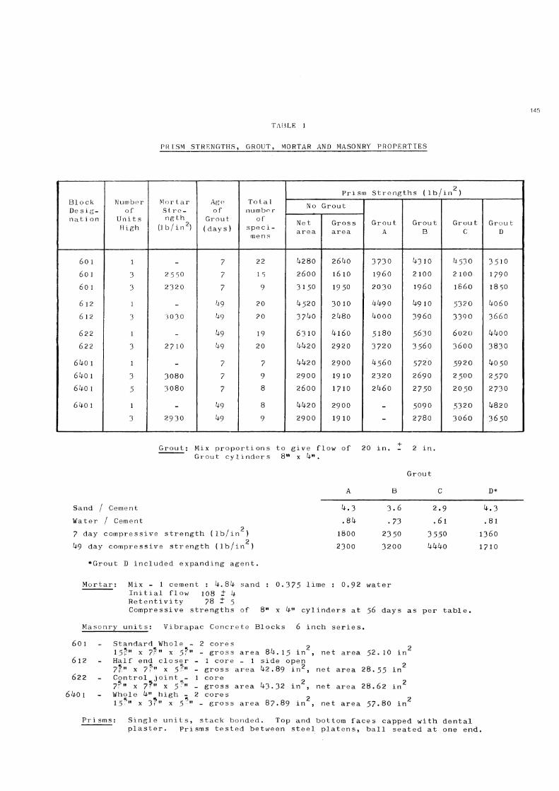
The author has recently conducted another series of compressive tests on concrete block prisms 1 , 3 and 5 units high with cores filled ] with grout of four different compressive
masonry under compressive load is given by Hilsdorf ( ̂ t>) . The development of stresses as they may occur in a single brick within a masonry element subjected to axial compression in the y direction is shown in Fig. 1 . It is assumed that the lateral tensile stresses in the x and z directions, * x and # z > are equal and they are given as a function of the local maximum stresses, & , which act in the direction of the external load. Line A is an assumed failure criterion for the triaxial strength of bricks (the actual one is not known and this assumption follows Mohr's theory of failure assuming a straight line envelope). With the masonry subjected to external uniaxial compression, the lateral tensile stresses follow the dashed line Bj until at the intersection with line A.local failure by cracking occurs causing a reduction in the lateral stresses. If the external load is already larger than the uniaxial compressive strength, then the mortar has been laterally confined. A certain minimum lateral compressive stress has had to act on the mortar and this must have been equilibrated by tensile stresses in the uncracked sections of the bricks. These minimum tensile stresses, which will increase with increasing external load, are represented by line C. When the external load is increased beyond the load causing the first crack, stresses in the uncracked section may develop along line Bg. A second crack will be formed when the stresses are such that B 2 intersects with A and again the lateral tensile stresses will fall to line C and the process continues in the same way and the brick may finally be split into small elements. Under the best conditions, the intersection of the failure criterion line A and the minimum lateral stress line C corresponds to the ultimate load of the masonry unit.
By expressing lines A and C mathematically the stress value at the point of intersection can be determined. Hilsdorf shows that:
145
PIUSM STRENGTHS, GROUT, MORTAR AND MASONRY PROPERTIES
Block De s ig-nation
Number of
Units High
Mortar Strength
(lb/ in 2)
Age of
Grout (day s)
Total numbfir
of specimens
Prism Strengths (lb/ in 2, Block De s ig-nation
Number of
Units High
Mortar Strength
(lb/ in 2)
Age of
Grout (day s)
Total numbfir
of specimens
No Grout
Grou t A
Grou t B
Grou t C
Grou t D
Block De s ig-nation
Number of
Units High
Mortar Strength
(lb/ in 2)
Age of
Grout (day s)
Total numbfir
of specimens
Net area
Gr os s area
Grou t A
Grou t B
Grou t C
Grou t D
60 1 1 _ 7 22 i*280 26^0 3 7 3 0 ^ 3 1 0 ^ 5 3 0 3 5 1 0
6 0 1 3 25 50 7 1 5 2 6 0 0 1 6 1 0 I 9 6 0 2 100 2 100 1 7 9 0
60 1 3 2 3 2 0 7 9 3 1 5 0 1 9 5 0 2 0 3 0 I 9 6 0 i 8 6 0 1 8 5 0
6 1 2 1 - 20 k$20 3 0 1 0 kk-9 0 U9 10 5 3 2 0 ko6o
6 1 2 3 3030 20 3 7 ^ 0 2^80 kooo 3 9 6 0 3 3 9 0 3 6 6 0
6 2 2 1 - k9 19 6 3 1 0 ^ 1 6 0 5 1 8 0 5 6 3 0 6 0 2 0 kkoo
6 2 2 3 2 7 1 0 k9 20 kkzo 2 9 2 0 3 7 2 0 3 5 6 0 3 6 0 0 3 8 3 0
6^0 1 1 - 7 7 kk2 0 2900 ^ 5 6 0 5 7 2 0 5 9 2 0 ^-050
6k 0 1 3 3080 7 9 2 9 0 0 19 10 2 3 2 0 2 6 9 0 2 5 0 0 2 5 7 0
6ko 1 5 3 0 8 0 7 8 2 6 0 0 1 7 1 0 2^60 2 7 5 0 2 0 5 0 2 7 3 0
6^0 1 1 _ kg 8 Zl42 0 2900 - 5 0 9 0 5 3 2 0 kS20
3 2 9 3 0 ^9 9 2 9 0 0 1 9 1 0 - 2 7 8 0 3 0 6 0 3 6 5 0
Grout: Mix proportions to give flow of 20 in. Grout cylinders 8 M x kn.
2 in.
Grout
A B C D*
Sand / Cement ^ . 3 3 . 6 2 . 9
Water / Cement . 8 ^ . 7 3 . 6 1 . 8 1
7 day compressive strength (lb/in 2) 1800 2 3 5 0 3 5 5 0 1 3 6 0
U-9 day compressive strength (lb/in 2) 2 3 0 0 3 2 0 0 kkko 1 7 1 0
•Grout D included expanding agent.
Mortar: Mix - 1 cement : ^ . 8 ^ sand : 0 . 3 7 5 lime : 0 . 9 2 wat er Initial flow 108 - k Retentivity 78 ± 5
Compressive strengths of 8" x ku cylinders at 56 days as per table.
Masonry units: Vibrapac Concrete Blocks 6 inch series. 6 0 1
6 1 2
6 2 2
6^0 1
Standard Whole 2 cores 1 5 ? " x 7 P " x 5 ? " - gross area 8 U . 1 5 in^, net area 5 2 . 1 0 in 2
Half end closer - 1 core - 1 side open 7 f " x ?f» x $?» - gross area k2.89 in 2, net area 2 8 . 5 5 in
1 core Control joint 7 ? " x 7^" x 5 Whole k" high 7 ? " x 7^" x 5 5 » - gross area ^ 3 - 3 2 in , net area 2 8 . 6 2 in
_ - 2 cores 1 5 ? " x 3 ? M x 5 5 » - gross area 8 7 . 8 9 in , net area 5 7 . 8 0 in
Pr i sms: Single units, stack bonded. Top and bottom faces capped with dental plaster. Prisms tested between steel platens, ball seated at one end.
T A B L E 1

146 seen by the steep fall off in load after the maximum stress was reached.
A further clue to the compressive behaviour of masonry is given by Fig. 7 which depicts the strain behaviour of mortar. Beyond the maximum load, there is a sharp increase in the lateral extension of mortar relative to its longitudinal contraction (for convenience this has been called Poisson's Ratio but of course the material is no longer elastic). Since the mortar is weaker in uni-axial compression than the masonry unit, the maximum mortar stress is attained before the maximum masonry stress and so the masonry unit is subjected to lateral tension from the mortar and eventually this causes the splitting failure of the masonry. The mortar is restrained by the masonry and so it is subjected to tri-axial compression and hence does not fail prematurely even if lower in uni-axial strength than the masonry. The phenomenon raises the question of the strength of masonry units in bi-axial tension - perhaps this is more important than our traditional insistence on high compressive strength units?
2 . 3 Shear Strength
See Under 3 . 3 Ultimate Strength of Walls.
3 . MASONRY SHEAR WALLS
3 . 1 Static Cyclic Test Behaviour
Scrivener and Williams^' have reported in the Bulletin on static cyclic tests on reinforced masonry walls subjected to in-plane loads applied at the top of the walls. The racking loads were cycled at constant amplitude representing a multiple (often k) of the load causing yield in the flexural steel. The wall aspect ratio, bearing loads and reinforcing were varied in turn and their effects on the ductility capabilities, stiffness degradation, load deterioration, failure mechanism and ultimate load capacity determined. They found that provided the flexural reinforcing at the wall ends and the bearing load were kept low and provided the aspect ratio (wall height to width) was high, the wall behaved in a most ductile manner as would be expected in a cantilever failing in flexure. The load deflection curves of Fig. 8 are typical of such a wall. Between the first and second cycles of loading the stiffness degraded but thereafter maintained its value and the maximum load remained reasonably constant. On reducing the aspect ratio to unity, ductile behaviour became most difficult to achieve and such walls failed in shear with typical diagonal cracking. Shear failure was also obtained when the flexural steel at the wall edges was increased as then the wall failed in shear at a load which was lower than that needed to yield the flexural steel. However, even with the brittle failure mode of shear, the load-deflect ion loops still had considerable area representing reasonable energy dissipative capacity. But they showed, with increasing number of cycles, load deterioration and stiffness degradation although at failure, where much larger deformations were required, load recovery was often exhibited -see, for example, Fig. 9 .
3 . 2 Dynamic Tests
Four walls, constructed exactly as the static test walls, were tested* 8* 1 1 ' under
strengths. The results are given in Table 1 along with details on the grout, mortar and masonry units. With the many variables in the test series, including grout and mortar strengths, and with the different combinations of variables used, it was necessary to statistically analyse the results to determine the significant differences, if any, in the means of the various sets of results. A 'one-way experimental layout' with a significance level of 5 $ was adopted ( 9 ) . A total of 2k mortar cylinders, ^8 grout cylinders and l 6 l prisms were tested with, where possible, 3 replicas of each test. Due to the limited capacity of the test machines at the University of Canterbury, both in load and in maximum distance between platens, 6 " blocks were all that could be accommodated. And even then, except for the half high blocks ( 6 ^ 0 1 ) , 3 high units were the limit and some tests had to be made at very early grout ages.
The conclusions which may be drawn from the results are;
a) 1 high prisms fail at much higher compressive loads and in a completely different manner from 3 high prisms. The effect of platen restraint causes inclined cracks and end crushing for the 1 high prisms, see Fig. 2 . But vertical splittling occurs with the 3 and 5 high prisms, see Fig. 3 , even with the squat 6^01 blocks, see Fig. k. The vertical cracks are precipitated in blocks away from the platens.
b) Although increasing the grout strength increases the single unit prism strength, it makes little difference to the compressive strength of prisms failing in the vertical splitting mode. This result and the observation that the grout and blocks separated easily at failure indicates the likelihood of bond breakdown, probably due to the shrinkage of the grout with its high water and relatively high cement content. The very limited tests with Grout D, containing an expanding agent, did not improve the situation but this is an area of development worth pursuing if higher prism strengths and hence higher wall compressive strengths are desired.
2 . 2 Stress-Strain Behaviour
As part of the investigation by Scrivener and Williams^?* 9 stress-strain curves for masonry units and for masonry prisms were determined. The results are shown in Figs. 5 and 6 indicating the same general pattern of behaviour for brickwork and concrete masonry as that already known for plain concrete. The brickwork prisms (Fig. 6 ) did tend to spall slightly at strains beyond the maximum load strain but the consequent fall in load was small and only gave rise to the "waviness" shown in the falling branch of the stress-strain curve. The slope of this part of the curve gives an indication of the material brittleness but for true comparison this slope must be related to the maximum stress obtainable for the specimen and so the slopes seen on the graphs (for different maximum stresses) are not direct measures of brittleness. For the specimens tested, the concrete masonry prisms were slightly more brittle than concrete of the same compressive strength whereas the brickwork tended to be slightly less brittle than the equivalent concrete. The brick unit itself exhibited a very brittle behaviour as can be

dynamic cyclic loading. The horizontal racking load was applied using the MTS closed loop electro-hydraulic structural loading system at N.Z. Pottery and Ceramic Research Association, Lower Hutt. The hydraulic pumping capability and servovalvo flow capacity limit the system performance so that as the cyclic frequency is increased the attainable displacement amplitudes are reduced. Accordingly for sinusoidal double amplitude frequencies of 0 . 5 " and 2 " the maximum attainable frequencies were approximately 1 hertz and 0 . 3 hertz respectively. Thus these tests were conducted at frequencies of 1 hertz or less.
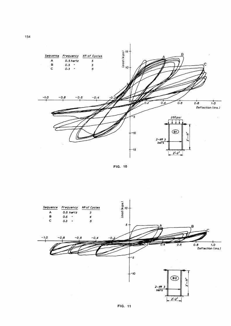
Generally the walls which showed some degree of load deterioration in the static testing behaved in a similar fashion under the dynamic conditions. Wall Bl was subjected to 5 cycles at 0 . 5 hertz and + 0 . ^ 3 " displacement in sequence A (see Fig. 1 0 ) compared with 3 cycles at t 0 . 5 0 " in the static series. In both cases the load capacity was maintained although minor stiffness degradation occurred. On increasing the displacement amplitude to 1" 0 . 6 2 " (sequence B) and 1 0 . 7 0 " in the dynamic and static situations respectively, mild deterioration occurred for both cases. Sequence C s a further 6 cycles at 0 . 3 hertz and j* 0 . 9 0 " displacement resulted in rapid deterioration, the load capacity in one direction falling from the maximum of 1 2 . 5 kip to k kip. In the static test there were no cycles at t 0 . 9 0 " displacement to allow comparison with the dynamic test.
The dynamic behaviour of wall B2, Fig. 1 1 , which according to static test results should have produced a satisfactory cyclic behaviour as the aspect ratio was relatively high, the amount of flexural steel was low and no bearing load was being carried, was surprising. Severe stiffness degradation and load deterioration were evident in the dynamic test. This wall may be compared with the most flexural situation in the static series, wall B3 (Fig. 8 ) which supported a bearing load of 1 2 5 psi and was subject to 3 cycles at a displacement of t 0 . 3 5 " , 2 cycles at + 0 . 6 5 " and 1 cycle at t 0 , 9 5 " followed by the final monotonic application of load to 3 " . For the dynamic test, sequence A of 3 cycles at a frequency of 0 . 5 hertz and a displacement of + 0 . ^ 0 " showed severe stiffness degradation whereas in the static situation only minor stiffness degradation occurred between the first and second cycle and thereafter stable behaviour prevailed. Sequence B of ^ cycles at 0 . 5 hertz and ± 0 . ? 0 " showed that further stiffness degradation took place while the load capacity reduced from k. 5 kip to 2 . 5 kip in 3 cycles. This trend was continued in sequence C, 6 cycles at 0 . 3 hertz and + 0 . 9 0 " . Overall the behaviour of B3 under static conditions was far more stable than the comparable dynamically tested wall.
Whereas a stable ductile action prevailed throughout the static test, for later cycles in the dynamic situation the wall deflect by sliding along the mortar bed above the second course. Due to the wall motion the products of material disintegration and crushing at the corner dislodged allowing buckling and bending of the reinforcing steel to occur. Thus the contribution of the compression zone and dowel action to the shear resistance became negligible. As the wall must then rely on "aggregate interlock" for shear resistance, bearing load may have been beneficial so that comparison of
these two walls may not be as favourable to the dynamic situation as at first thought.
It is suggested that effective confinement of the reaction corner material, possibly difficult to achieve, would prevent this undesirable behaviour. Also the confinement of the masonry would prevent early buckling and so retain the steel couple as an effective seismic load resisting element.
A movie film of the dynamic tests shows very graphically the pattern of wall cracking and the disintegration and dislodgement of masonry in the reaction corner.
3 . 3 Ultimate Strength of Walls
The load to cause yielding of the flexural reinforcing in a wall was able to be predicted, in the above tests, to within a few percent by equilibrating moments of all the forces acting (racking load, bearing load, yield forces in reinforcing) about the wall toe (i.e. by assuming that the centre of compression is at the wall toe and treating the wall as reinforced concrete).
For those walls in which shear determined the maximum load, the shear strength (ultimate shear stress based on the gross horizontal section) varied from 150 to 260 lb/in, 2 These values may be compared with a near constant value of lk3 lb/in^ for a wide range of walls from Schneider's tests ( 1 2 ) and an average value of 1 7 0 lb/in 2 for those concrete block walls from Scrivener's series containing the optimum 0 , 3 % reinforcing or greater. The higher values were associated with walls supporting large bearing loads.
3•^ Shear Walls with Openings
An experimental evaluation of the capacity of reinforced concrete masonry piers, functioning within the confines of a shear wall, to resist lateral load was conducted by Schneider ' ^ J , The static load was applied diagonally and the major variables were the amount of web reinforcing both vertical and horizontal and the ratio !L (where a is the distance of the point of inflection to spandrel restraint and D is trie overall pier depth). Schneider found that the shear strength (horizontal component of ultimate load over pier cross sectional area) increased with a decrease in the ^ ratio, from
2 D shear strength 100 lb/in at ^ = 1 . 5 to 280 lb/in 2 at — = 0 . 1 7 . At higher ~ values, lower shear strengths down to 50 lb/in^ were reported but as, in these cases, the failure appeared to be flexural the figures are not true shear strengths as failure occurred earlier by other than shear.
Where horizontal reinforcement was provided a significant increase, of the order of 50%, in the shear strengths was obtained. Vertical steel did not seem to be effective as web reinforcement which Schneider explains as "it does not contain the grout within the masonry as do horizontal stirrups". It should be noted that diagonal loading demands a diagonal crack type failure.
( 1 ^ 1e\
Krishna and Chandra describe some tests on model brick houses with different

148 quake without total collapse. A ductile structure fulfils this dual role very efficiently and such a condition is normally attained by ensuring a flexural type failure with tensile yielding of the steel. For ductile behaviour it is appropriate to use Code prescribed loads and design tho wall as a vertical beam by an ultimate strength method similar to that used in reinforced concrete.
If a sufficiently ductile behaviour cannot be confidently predicted (and it appears that this would usually be -the case at present) the structure must be designed to withstand forces associated with the design earthquake which may be several times the code specified values which have proved satisfactory design loads for ductile framed structures. On the other hand, code specified allowable stresses should be realistic.
k. FACE LOADING OF MASONRY WALLS
Loading perpendicular to the masonry surface (face loading), causing bending of the wall, has received much research attention overseas for unreinforced walls and combined bending and compressive loading of unreinforced walls has also been re searched' 1 ?).
Two series of face loading tests on reinforced brick walls have been conducted by Scrivener. In the first( l 8 > , monot oni c uniformly distributed face load was applied by air bag to one face of walls simply supported at their ends. A valid criticism of these tests was that since the walls were rotated to lie in the horizontal plane so that the air bag reacted against the floor, the wall dead weight was incorrectly applied. Accordingly, in the second series, the walls were kept in their natural vertical orientation and a vertical platform constructed for the air bag loading reaction. The base of the wall was mounted on roller bearings and to ensure simple support end conditions the base and top of the wall were attached to the reaction platform by horizontal hinged rods allowing free rotation of the wall ends. These rods, suitably strain gauged, were also used as load cells to check the magnitude of air bag loading. The test set-up is shown in Fig. 1 2 . A few cycles of static face load were conducted, the reverse loading being obtained by applying the air bag load to the other face of the wall. Load deflection curves were found.
The details of the walls and the yield (ultimate) loads are given in Table 2 . A typical load-deflection plot from one of the walls is recorded in Fig. 1 3 . In both test series it was found that the test yield load (ultimate load) could be predicted to within a few percent by considering the reinforced brick section as a lightly reinforced wide beam and applying ultimate moment theory as for reinforced concrete. The stress-strain curve for the brick was assumed to be the same as that for concrete in order that the concrete constant 0 . 5 9 within the Whitney equation could be used. The ultimate moment, M • is :
u M = A f (d - O . 5 9 A f / f • b) u s y ^ s y ' c
where A = cross sectional area of steel-s f = yield stress of steel
arrangements of reinforcing. They demonstrate that vertical re i nf orcemo n t in the corners and jambs increase the strength and ductility of a structure considerably. A suggestion is made for limits for the percentage of reinforcing to be used for economical and efficient performance of the walls.
3 . 5 Masonry Infill Pannls
The behaviour of masonry diaphragms framed by reinforced concrete members has received some attention by research workers largely in determining the capacity under single load application. E s t e v a ^ 1 ^ however has gone further and produced lateral load versus angular deformation curves for many cycles of load.
When the masonry wall is enclosed in a structural frame the total structure becomes a very stiff shear wall. At some critical deformation diagonal cracking of the masonry occurs very often with simultaneous cracking of the frame and the load that the structure takes decreases suddenly. Further cycling causes much damage to the masonry. It is for this reason that one New Zealand philosophy of design for frames with masonry infill panels is to isolate the panel from the frame so that the frame carries the in-plane earthquake force and the panel is only called on to carry earthquake loads perpendicular to itself and created by its own mass - for behaviour see Section U Face Loading. Some research in Portugal has shown that even with "isolation 1 1 of panel from frame, the masonry can affect the stiffness and behaviour of the frame. It is hoped to investigate this phenomenon at Canterbury shortly but in the meantime if panel isolation is desired considerable care should be taken in the detailing and construction.
3 • 6 Summary of Masonry Shear Wall Behaviour -De sign
Tests have shown that, provided the masonry in the wall reaction corners is confined, a ductile generally satisfactory post-elastic behaviour suitable for seismic resistance can be obtained under certain conditions. The shear strength of the load bearing section must exceed the ultimate flexural strength which can be predicted by equating the moment of the racking load about the wall base to the algebraic sum of the moments of the bearing loads and of the vertical reinforcing yield forces taken about the reaction corner. The shear strength over a wide range of masonry tests in New Zealand and U.S.A. has a minimum value of around 1 5 0 lb/in 2 provided that shear is the failure mode. A further condition is in the wall geometry. Walls satisfying the above conditions and with aspect ratio two (or •greater) were ductile but for walls with jaspect ratio one or less true ductile behaviour was not found. However the energy dissipating icapacity of non ductile walls may still be 1arge and these walls may not be unsatisfactory in seismic situations.
Current seismic design philosophy suggests that the energies associated with large earthquakes should preferably be dissipated by :inelastic deformations. The structure should ;be designed to withstand "moderate" earthquakes without major structural damage and should also be capable of withstanding a "severe" earth

TABLE 2
CYCLIC FACE LOADING OF REINFORCED BRICK WALLS - TEST RESULTS AND WALL DETAILS
Wall Reinf orcement Yield Loads (lb/ft 2)
Wall Reinf orcement The ore t i cal Experimental
None 32
2 -- |" diam. 31 33
3 -- 1 " diam. k6 k2
k . - |" diam. 6l 6k
3 -- |" diam. 77 8k
Bricks: McSkimmings reinforcing and lattice bricks
Walls; Brickwork 10' high x 5' wide support ed on RC beams at base and top.
Reinforcing: Vertical deformed bar s in grou ted cores, lapped with starter bars from RC beams.

d = depth to centre of gravity of steel b = beam width f• = brick crushing strength c
As the contentious figures f c and 0 . 5 9 appear only in the 2 n d term within the bracket s and thi s term only affect s re suit s by approximately 2% (since the beam is very 1ightly reinforced) the se apparently gro ss assumpt ions are justified.
With such a relatively large span in relation to the section depth and with the low reinforcing content, it is hardly surpri sing that flexure was the dominant action giving a highly ductile behaviour characterised by large inelastic deformations (and cracking). But even with deformations of 6 " and greater there was never any sign of bricks wishing to separate from the wall. The hysteresis 1 oops of the load-deflection diagram are large, if narrow gut ted due to the ineffective position of the reinforcing in the centre of the section. The yield 1oads are much in excess of code pre scribed earthquake loads ( 0 . 3 2 g f or zone A public building which is l 6 lb/ft 2 f or the se walls).
5 . CONCLUSION
Over the last few year s consi derable knowledge has been gained about the behaviour of re inforeed masonry unde r load. Monotonically increasing load give s some indicat ion of initial strength and deformation but for seismic design repeated cyclic 1oading gives more useful informat ion particularly about ductility, st if f-ne ss degradation, load deteriorat ion and energy di ssipative capacity.
The inf ormati on from stat ic tests may also be incomplete, as some dynamic tests have shown up factors hitherto unconsidered. One dynamic test has shown the need for confinement of masonry and steel in the reaction corner of masonry shear walls in order to maintain the full ductility and load capacity of ductile walls.
Both in material and in element behaviour, masonry has been shown to act similarly to the other brittle con struct ion material, concrete. Much of the knowledge gained on re inforced cone re te behaviour may be applied to reinforced masonry structures.
6. ACKNOWLEDGEMENTS
The author is most grateful to the Civil Engineering Department, University of Canterbury, McSkimming Indust ries Ltd. , N.Z. Pottery and Ceramics Re search Associat ion and Vibrapac Blocks Limited for assistance in the tests.
?. REFERENCES
1• Holmes, I.L., "Masonry Seismic Design -Seminar on Sei smic Problems in Structural Engineering", University of Canterbury, May 1 9 6 8 .
2a. Polyakov, S.V., "Seismic Resistant Structures in the USSR."
2b. Izumi, M., "Principles of Earthquake Resistant Construction" - Build International, Vol. 5 , No. 1, January/February 1 9 7 2 .
3• Sahlin, S., "Structural Masonry" - Prentice-Hall, 1 9 7 1 .
Holmes, I.L., "Masonry Building in High
Intensity Seismic Zones." kb. Hilsdorf, H.K., "Investigation into the
Failure Mechani sm of Brick Masonry Loaded in Axial Compre ss ion."
kc . Scrivener, J.C., "Static Racking Te st s on Concrete Masonry Walls" - Proceedings International Conference on Masonry Structural Sy stems, Texas, Nov. 1 9 6 7 and publi shed as "Designing, Engineering and Con struct ing with Masonry Product s" edited by Johnson, F.B., Gulf Publi shing Co., Houston, 1 9 6 9 .
5. Shepherd, R., "Some Aspe ct s of the San Fernando Earthq uake" - N.Z. Engineer ing, Vol. 2 7 , No. 2, Feb. 1 9 7 2 .
6. Newman, K. , and Lachance, L. , "The Tes ting of Brittle Materials Under Uniform Uniaxial Compressive Stress" - Proceedings American Society for Testing and Materials, Vol. 6k, 196k, pp 1 0 * 4 4 - 6 7 .
7 . Scrivener, J.C. and Williams, D., "Compressive Behaviour of Masonry Prisms" - Proceedings Third Australasian Conference on the Mechanics of Structures and Materials, Auckland, August 1 9 7 1 .
8 . Williams, D., "Seismic Behaviour of Reinforced Masonry Shear Walls" - Ph.D. Thesis, University of Canterbury 1 9 7 1 .
9 . Kreyszig, E., 11 Introductory Mathematical Statistics", Wiley 1 9 7 0 , p p 2 6 2 - 2 7 3 .
1 0 . Scrivener, J.C. and Williams, D,, "Behaviour of Reinforced Masonry Shear Walls Under Cyclic Loading" - Bulletin of N.Z. Society for Earthquake Engineering, Vol. k, No. 2 , April 1 9 7 1 .
1 1 . Williams, D. and Scrivener, J . C , "Response of Reinforced Masonry Shear Walls to Static and Dynamic Cyclic Loading" - Accepted for presentation at 5 t h World Conference on Earthquake Engineering, Rome, Italy, June 1 9 7 3 .
1 2 . Schneider, R.R., "Lateral Load Tests on Reinforced Grouted Masonry Shear Walls" - University of Southern California Engineering Centre Report No. 7 0 - 1 0 1 , September 1 9 5 9 .
1 3 . Schneider, R.R., "Shear in Concrete Masonry Piers" - Reports of Tests at California State Polytechnic College, Pomona, California 1 9 6 9 .
1^. Krishna, J. and Chandra, B., "Strengthening of Brick Buildings Against Earthquake Forces" - Proceedings 3 r d World Conference on Earth-Quake Engineering, N.Z., 1 9 6 5 , Vol. Ill pp 3 2 ^ - 3 ^ 1 .
1 5 . Krishna, J. and Chandra, B., "Strengthening of Brick Buildings in Seismic Zones" - Proceedings i*th World Conference on Earthquake Engineering, Chile, Jan. 1 9 6 9 , B6 pp 1 1 - 2 0 .
1 6 . Esteva, L., "Behaviour Under Alternating Loads of Masonry Diaphragms Framed by Reinforced Concrete Members" - International Symposium on the Effects of Repeated Loading of Materials and Structural Elements, Rilem, Mexico, September 1 9 6 6 .
1 7 . Yokel, F.Y., Mathey, R.G. and Dikkers, R.D., "Effect of Vertical Compressive Loads on the Transverse Strength of Masonry Walls" -National Bureau of Standards Report, U.S. Dept. of Commerce, Washington D.C., December 1 9 6 9 .
1 8 . Scrivener, J . C , "Face Load Tests on Reinforced Hollow Brick Non-Load-Bearing Walls" - N.Z. Engineering, July 1 9 6 9 * pp. 2 1 5 -2 2 0 .

FIG. 4

3500
£^=J28£ lb/in*
0-2 0.4 0.6 0.8 UO Strain (V.)
F I G . 5
FIG. 6

153
0.6 0-8 Strain (V,)
FIG. 7
Cycle numbers are indicated
Load maintained to 3'deflection •
FIG. 8
-0.4 -0.2'
% 36-
o 24-
12-
—^-0.1
-12~
^ S - 2 4 -
-36-
Cycle numbers are indicated
0.2 0.3 0.4 Deflection (in.)
6-N*3
6'-1"
FIG. 9
154
Sequence Frequency A/s of Cycles A 0.5 hertz 5 B 0.5 " 5 C 0.3 " 6
F I G . 1 0
Sequence
0.6 1.0 Deflection (ins)
2~m 3 bars 1
/77 7">T7'>/yf
F I G . 1 1

FIG. 13

![M-4-Paulay & Priestley [Seismic Design of Reinforced Concrete and Masonry Buildings] Ch 1&2](https://img.pdfslide.net/doc/110x75/55cf862a550346484b94e7d2/m-4-paulay-priestley-seismic-design-of-reinforced-concrete-and-masonry-buildings.jpg)