Embed Size (px)
Citation preview
7
1
Release Notes 4900 Electric Drive
4900 Electric Drive V4.0 Bundle
Release Date: 3/13/2017
Contents Released Version Numbers ........................................................................................................................... 2
1.0 New Features .......................................................................................................................................... 2
2.0 Improvements ......................................................................................................................................... 2
3.0 Known Planter Software Issues............................................................................................................... 4
3.1 Known 4900 Electric Drive V2 Seed Sensor Issues (SW Version 2.0) ................................................. 4
4.0 Approved Displays................................................................................................................................... 5
4.1 Display Improvements ........................................................................................................................ 5
4.2 Known Raven Viper 4 Issues ............................................................................................................... 6
4.3 Known John Deere 2630 Issues .......................................................................................................... 6
4.4 Known CNH Issues............................................................................................................................... 7
4.5 Known Ag Leader Issues ...................................................................................................................... 7
5.0 Approved GPS Receivers ......................................................................................................................... 8
5.1 Notes on GPS Accuracy ....................................................................................................................... 8
5.2 GPS Frequency .................................................................................................................................... 8
6.0 Notes on Section Control ........................................................................................................................ 9
6.1 Effects of GPS Accuracy on Section Control ........................................................................................ 9
6.2 Effects of Communication Timing on Section Control ........................................................................ 9
6.3 Effects of Driving Habits on Section Control ..................................................................................... 10
6.4 Effects of External Variables on Section Control .............................................................................. 10
6.5 Effects of Display Variability on Section Control ............................................................................... 11
6.6 Reasonable Expectations for Section Control Performance ............................................................. 11
7.0 How to Update ...................................................................................................................................... 12
8.0 Electronics Pre-Season Check Out ........................................................................................................ 23
9.0 Diagnostics ............................................................................................................................................ 26

7
2
Release Notes 4900 Electric Drive
4900 Electric Drive V4.0 Bundle
Release Date: 3/13/2017
Released Version Numbers
1.0 New Features
• Approved display list expanded to include Ag Leader’s InCommand 1200 display
2.0 Improvements • Down Force Alarm Generation
o High down force alarm message corrected • Down Force Pre-filling
o Changed the down force terminology “Lifted Compensation” to “Prefill Percentage” • Individual Row Singulation, Bar Graph and Alarms
o Singulation percentages for individual rows (accuracy, skips and doubles) now display with a resolution of 0.1 %
o Eliminated occasional brief disappearance of individual row on bar graph o Eliminated occasional Lost Communication alarms for individual rows
• Section Control o Manual section control buttons now function while the task controller is enabled o Improved row-to-row seed meter turn on/off consistency
• Custom Crop Setup o Default setup values added for three seed meter-related measurements o Seed sensor configuration updated when custom crop settings revised o Custom crop disc setup now supports cell counts up to 250 o Custom crop bulk fill vacuum pressure setting now saved
• Test Diagnostics o Added separate Seed, Fertilizer, and Insecticide test buttons on the Task Controller
settings page o Row numbers display correctly now with all approved displays o Manual run button works now for Fertilizer when Insecticide not installed
• Alarm History o Expired alarms are now identified and listed below active alarms within Alarm History o Population alarms no longer occur for rows set to 0 rate within the By-Row option
• Prime/Flush o Prime and Flush operations are now consistently available for all products
• Diagnostic File Export o Master Module SW version now correctly reported in diagnostic file export
• Jump Start o Improved performance during Jump Start transitions from 0 mph to GPS-based speed
Module Version Master Module 4.0 I/O Module 1.2.0 Row Module 2.4.3 Motor Drive Module 2.3.0 Seed Sensor 2.0.4

7
3
Release Notes 4900 Electric Drive
4900 Electric Drive V4.0 Bundle
Release Date: 3/13/2017
• Module Software Updates o Row Module software updates are now valid after a Master Module software update
• Diagnostic Features o If Fertilizer or Insecticide are not installed, they no longer appear in diagnostic statuses o Improved alarms and reconfiguration result associated with disconnected wing fuses
• Marker Deployment o Fixed occasional failure-to-deploy of marker when auto marker switching is enabled
7
4
Release Notes 4900 Electric Drive
4900 Electric Drive V4.0 Bundle
Release Date: 3/13/2017
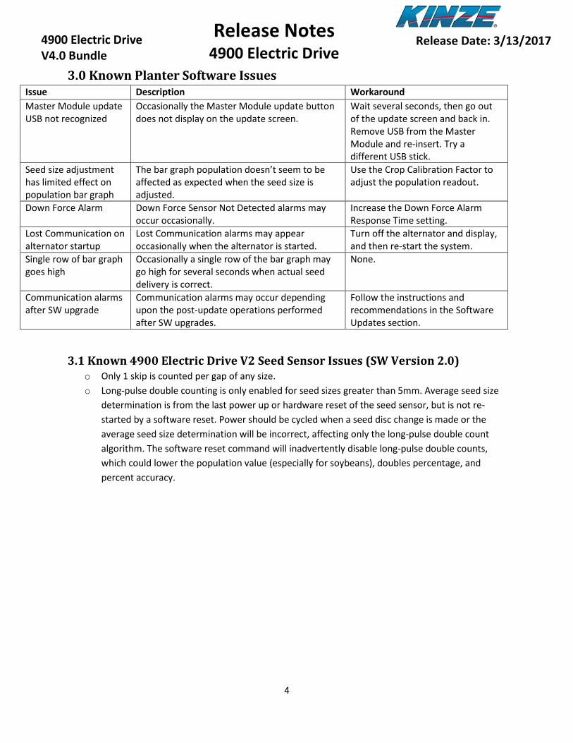
3.0 Known Planter Software Issues Issue Description Workaround Master Module update USB not recognized
Occasionally the Master Module update button does not display on the update screen.
Wait several seconds, then go out of the update screen and back in. Remove USB from the Master Module and re-insert. Try a different USB stick.
Seed size adjustment has limited effect on population bar graph
The bar graph population doesn’t seem to be affected as expected when the seed size is adjusted.
Use the Crop Calibration Factor to adjust the population readout.
Down Force Alarm Down Force Sensor Not Detected alarms may occur occasionally.
Increase the Down Force Alarm Response Time setting.
Lost Communication on alternator startup
Lost Communication alarms may appear occasionally when the alternator is started.
Turn off the alternator and display, and then re-start the system.
Single row of bar graph goes high
Occasionally a single row of the bar graph may go high for several seconds when actual seed delivery is correct.
None.
Communication alarms after SW upgrade
Communication alarms may occur depending upon the post-update operations performed after SW upgrades.
Follow the instructions and recommendations in the Software Updates section.
3.1 Known 4900 Electric Drive V2 Seed Sensor Issues (SW Version 2.0) o Only 1 skip is counted per gap of any size. o Long-pulse double counting is only enabled for seed sizes greater than 5mm. Average seed size
determination is from the last power up or hardware reset of the seed sensor, but is not re-started by a software reset. Power should be cycled when a seed disc change is made or the average seed size determination will be incorrect, affecting only the long-pulse double count algorithm. The software reset command will inadvertently disable long-pulse double counts, which could lower the population value (especially for soybeans), doubles percentage, and percent accuracy.
7
5
Release Notes 4900 Electric Drive
4900 Electric Drive V4.0 Bundle
Release Date: 3/13/2017
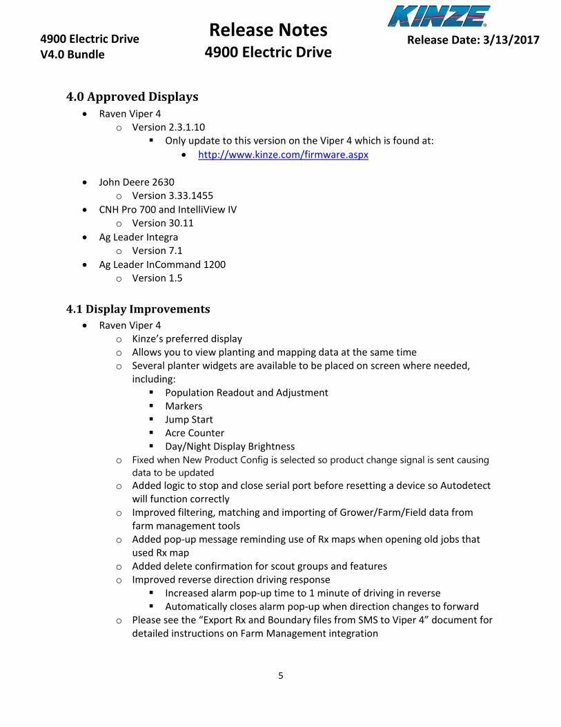
4.0 Approved Displays • Raven Viper 4
o Version 2.3.1.10 Only update to this version on the Viper 4 which is found at:
• http://www.kinze.com/firmware.aspx
• John Deere 2630 o Version 3.33.1455
• CNH Pro 700 and IntelliView IV o Version 30.11
• Ag Leader Integra o Version 7.1
• Ag Leader InCommand 1200 o Version 1.5
4.1 Display Improvements • Raven Viper 4
o Kinze’s preferred display o Allows you to view planting and mapping data at the same time o Several planter widgets are available to be placed on screen where needed,
including: Population Readout and Adjustment Markers Jump Start Acre Counter Day/Night Display Brightness
o Fixed when New Product Config is selected so product change signal is sent causing data to be updated
o Added logic to stop and close serial port before resetting a device so Autodetect will function correctly
o Improved filtering, matching and importing of Grower/Farm/Field data from farm management tools
o Added pop-up message reminding use of Rx maps when opening old jobs that used Rx map
o Added delete confirmation for scout groups and features o Improved reverse direction driving response
Increased alarm pop-up time to 1 minute of driving in reverse Automatically closes alarm pop-up when direction changes to forward
o Please see the “Export Rx and Boundary files from SMS to Viper 4” document for detailed instructions on Farm Management integration
7
6
Release Notes 4900 Electric Drive
4900 Electric Drive V4.0 Bundle
Release Date: 3/13/2017
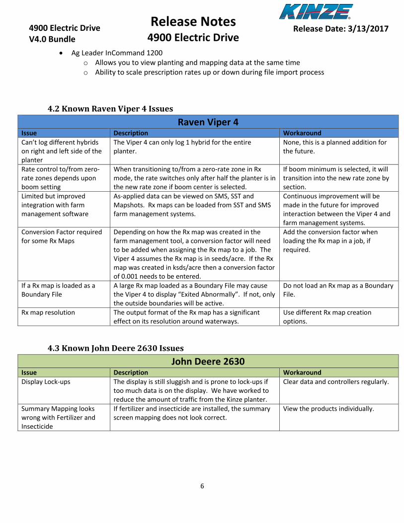
• Ag Leader InCommand 1200 o Allows you to view planting and mapping data at the same time o Ability to scale prescription rates up or down during file import process
4.2 Known Raven Viper 4 Issues
Raven Viper 4 Issue Description Workaround Can’t log different hybrids on right and left side of the planter
The Viper 4 can only log 1 hybrid for the entire planter.
None, this is a planned addition for the future.
Rate control to/from zero-rate zones depends upon boom setting
When transitioning to/from a zero-rate zone in Rx mode, the rate switches only after half the planter is in the new rate zone if boom center is selected.
If boom minimum is selected, it will transition into the new rate zone by section.
Limited but improved integration with farm management software
As-applied data can be viewed on SMS, SST and Mapshots. Rx maps can be loaded from SST and SMS farm management systems.
Continuous improvement will be made in the future for improved interaction between the Viper 4 and farm management systems.
Conversion Factor required for some Rx Maps
Depending on how the Rx map was created in the farm management tool, a conversion factor will need to be added when assigning the Rx map to a job. The Viper 4 assumes the Rx map is in seeds/acre. If the Rx map was created in ksds/acre then a conversion factor of 0.001 needs to be entered.
Add the conversion factor when loading the Rx map in a job, if required.
If a Rx map is loaded as a Boundary File
A large Rx map loaded as a Boundary File may cause the Viper 4 to display “Exited Abnormally”. If not, only the outside boundaries will be active.
Do not load an Rx map as a Boundary File.
Rx map resolution The output format of the Rx map has a significant effect on its resolution around waterways.
Use different Rx map creation options.
4.3 Known John Deere 2630 Issues
John Deere 2630 Issue Description Workaround Display Lock-ups The display is still sluggish and is prone to lock-ups if
too much data is on the display. We have worked to reduce the amount of traffic from the Kinze planter.
Clear data and controllers regularly.
Summary Mapping looks wrong with Fertilizer and Insecticide
If fertilizer and insecticide are installed, the summary screen mapping does not look correct.
View the products individually.

7
7
Release Notes 4900 Electric Drive
4900 Electric Drive V4.0 Bundle
Release Date: 3/13/2017
4.4 Known CNH Issues
Case Pro 700 Issue Description Workaround Turning Compensation hard to setup
It takes several steps to enable the GPS messages needed to make turning compensation work. Also need to have the correct harnessing on the top of the tractor near the GPS globe.
Instructions are available.
General issues with Data Card being full
If the USB and display memory gets too full, random issues will appear with the display and planter
Workaround is to clear display and USB memory often.
4.5 Known Ag Leader Issues Ag Leader Integra and InCommand
Issue Description Workaround Planter flipping in front of tractor on display
There have been multiple reports during testing that the planter will flip in front of the tractor which causes section control to work improperly. It usually isn’t detected unless the display is on the map view.
Disable Heading Direction or use the Heading Change button on the display.
7
8
Release Notes 4900 Electric Drive
4900 Electric Drive V4.0 Bundle
Release Date: 3/13/2017
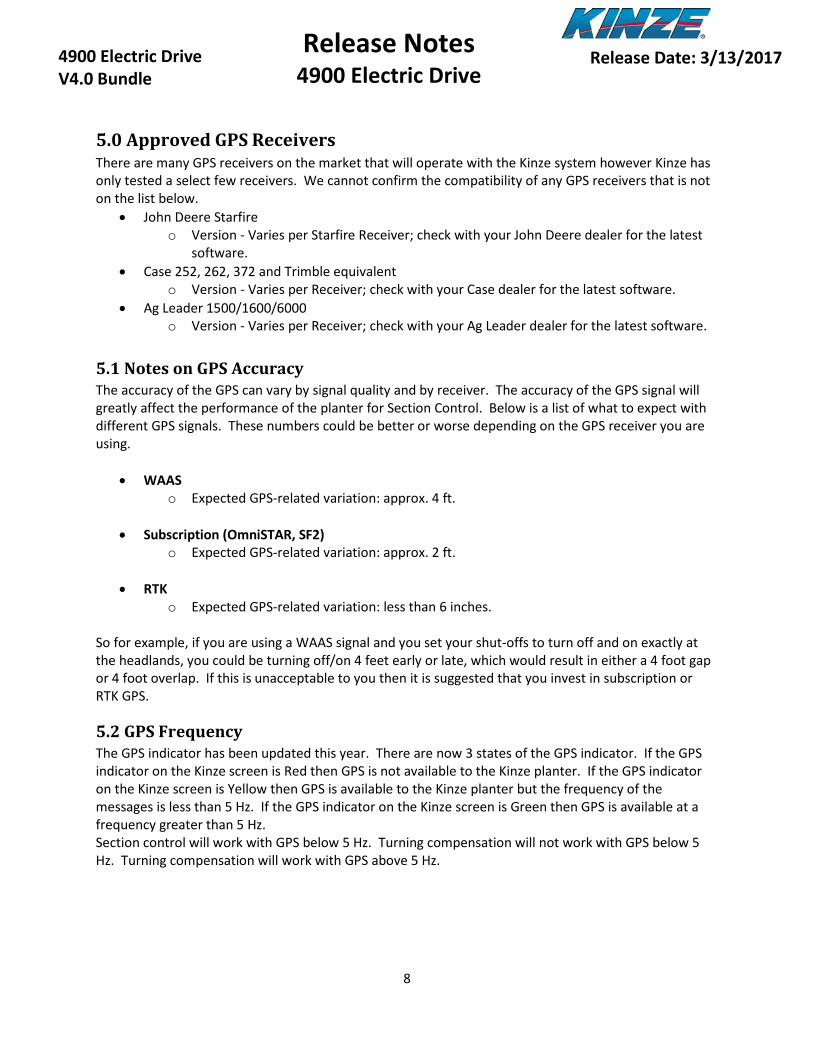
5.0 Approved GPS Receivers There are many GPS receivers on the market that will operate with the Kinze system however Kinze has only tested a select few receivers. We cannot confirm the compatibility of any GPS receivers that is not on the list below.
• John Deere Starfire o Version - Varies per Starfire Receiver; check with your John Deere dealer for the latest
software. • Case 252, 262, 372 and Trimble equivalent
o Version - Varies per Receiver; check with your Case dealer for the latest software. • Ag Leader 1500/1600/6000
o Version - Varies per Receiver; check with your Ag Leader dealer for the latest software.
5.1 Notes on GPS Accuracy The accuracy of the GPS can vary by signal quality and by receiver. The accuracy of the GPS signal will greatly affect the performance of the planter for Section Control. Below is a list of what to expect with different GPS signals. These numbers could be better or worse depending on the GPS receiver you are using.
• WAAS o Expected GPS-related variation: approx. 4 ft.
• Subscription (OmniSTAR, SF2)
o Expected GPS-related variation: approx. 2 ft.
• RTK o Expected GPS-related variation: less than 6 inches.
So for example, if you are using a WAAS signal and you set your shut-offs to turn off and on exactly at the headlands, you could be turning off/on 4 feet early or late, which would result in either a 4 foot gap or 4 foot overlap. If this is unacceptable to you then it is suggested that you invest in subscription or RTK GPS.
5.2 GPS Frequency The GPS indicator has been updated this year. There are now 3 states of the GPS indicator. If the GPS indicator on the Kinze screen is Red then GPS is not available to the Kinze planter. If the GPS indicator on the Kinze screen is Yellow then GPS is available to the Kinze planter but the frequency of the messages is less than 5 Hz. If the GPS indicator on the Kinze screen is Green then GPS is available at a frequency greater than 5 Hz. Section control will work with GPS below 5 Hz. Turning compensation will not work with GPS below 5 Hz. Turning compensation will work with GPS above 5 Hz.

7
9
Release Notes 4900 Electric Drive
4900 Electric Drive V4.0 Bundle
Release Date: 3/13/2017
6.0 Notes on Section Control Setting up section control can be a lengthy process and at times a frustrating process. In this section we will attempt to explain what error factors can impede the set-up process and what expectations should be for shut-off accuracy.
6.1 Effects of GPS Accuracy on Section Control GPS accuracy is one of the biggest factors in the accuracy of Section Control. Getting accurate shut-off performance will be impossible without a good GPS signal. This can vary by signal quality but also by receiver. Not all receivers are created equal; one brand of receiver might work better than another using the same signal.
You can use WAAS signal for Section Control, but if you do this you are accepting the fact that your turn on and offs may be +/- 4 feet for accuracy. If that is acceptable to you, then WAAS is fine; if not, a Subscription or RTK signal is required. Full lists of signal accuracies are available in Section 5.1.
6.2 Effects of Communication Timing on Section Control Many messages need to be sent back and forth between the GPS Receiver, Display, and Planter to make section control accurate. For example, below is the typical sequence of events for a shut-off.
1. GPS receiver sends a signal to the Display 2. Display processes the message and determines it needs to shut sections off 3. The Display sends a message out on the ISOBUS to the Master Module to shut rows off 4. The Master Module processes the message and sends out messages to the Row Modules
individually to shut rows off 5. The Row Modules then process the messages and send out messages to the Motor Drive
Modules to shut the motors off 6. The Motor Drive Modules process the commands and shut the motors off
As you can see there are many messages to relay, and while it only takes milliseconds to send the messages, there is inevitably variation in the time it takes to process and send messages. We have optimized this process; however, it is still possible to see roughly +/- 8 inches of pass-to-pass variability in the field if you were traveling at 6mph.

7
10
Release Notes 4900 Electric Drive
4900 Electric Drive V4.0 Bundle
Release Date: 3/13/2017
6.3 Effects of Driving Habits on Section Control Section Control is much more accurate if a few basic driving rules are followed.
1. Make sure you drive at a constant speed in and out of the headlands. Due to the communication lag and time for seed to stop falling from the meter, the display will actually send the command to turn on/off before you leave or enter the headlands. So if you are slowing down right before you come into the headland, the section control will shut off too early because it was shutting off for a faster speed.
a. If you plan to slow down for the headlands, do so 100 feet before you enter the headlands and maintain that speed until the rows have turned back on coming out of the headlands. Also make sure when you set your shut-offs that you are traveling the same speed as you will be in the field.
2. Make sure you get the planter down in time coming out of the headlands. If you do not get your planter down in time there will be gaps.
a. To avoid this, it is recommended that you get the planter in the ground at least 10 feet before you leave the headlands.
3. Make sure the planter is straight before you leave the headlands. If you are still turning as you leave your headlands, this could cause erratic performance of the shut-offs because the outside of the planter is traveling at a higher speed than the inside of the planter. This doesn’t mean you have to be 90 degrees to the headland but you need to be on the path you intend to drive before you leave the headlands.
a. To avoid this, it is recommended that the planter be on the intended path at least 10 feet before the first row leaves the headlands.
6.4 Effects of External Variables on Section Control Beside the factors listed above, there are several other variables that can affect how the section control performance looks in the ground. These are discussed below. Seed Disc Position When the seed meters turn on or off they all start out in different positions. Therefore you could have up to a seed of difference in the time it takes to turn on or off. So if your seed spacing is 6 inches you could have up to a +/-3 inch variation row to row on turn on and off. Seed Tube Bounce The bounce coming down the seed tube could vary slightly row to row and in rough conditions will vary more. In good conditions the variation due to this will be minimal, but in rougher conditions the variation could be +/-3 inches for 6 inch seed spacing. Electric Motor Start-up Electric motors are not like a clutch where you have instant starts and stops. Motors need to ramp up to avoid stalls. The ramp up takes roughly 0.25 seconds. At a seed spacing of 6 inches this will usually result in one skip at start-up. It is recommended that when setting the turn ons, you measure from where the row is up to full population and disregard the first seed that falls.

7
11
Release Notes 4900 Electric Drive
4900 Electric Drive V4.0 Bundle
Release Date: 3/13/2017
6.5 Effects of Display Variability on Section Control Each display has its own algorithms for calculating when a row should be on and off, and at times they can vary quite a bit. For example, if you are coming into your headlands at a slight angle, say 88 degrees to the headlands, some displays might choose to shut the planter all off at the same time because the time to shut the first row off compared to the last is so small. However on a 60-foot planter this would still result in a 2-foot difference from one side of the planter to the other. Alternatively, other displays may have very sensitive algorithms that try to shut all the rows off sequentially no matter how close they are to shutting off together. This can cause the same issue on a perfect 90-degree headland approach because the rows will shut off in a linear fashion even when they should shut off all together. It is hard to put a number on this variability; see your display manufacturer for their accuracy ratings.
6.6 Reasonable Expectations for Section Control Performance Now that we have discussed all the factors that go into the accuracy of section control performance, let’s see how the accuracies stack up. For this example, let’s say I am using WAAS GPS signal in No-Till conditions that are somewhat rough, and moving at 6mph. This example also assumes you are using the recommended driving habits in Section 6.3 and disregarding the first few seeds on start-up as discussed in section 6.4 on Electric Motor Start-up. Failing to do either of these will result in larger variation. As you can see below, if you add up all of the possible inaccuracies of the planter, you will get a possible pass-to-pass variation of up to +/- 12 inches. In many cases this could be better, and in other cases it could be worse based on the factors discussed in Section 6.5 (Display Variations).
Then if we add in the variation for WAAS of +/-48 inches, our variation from pass to pass could be up to 60 inches. In most cases the accuracy will be better than this; however, depending on signal quality and GPS receiver brand, it could also be worse. If we bumped up to subscription GPS our variation would go down to +/-36 inches, and if we went to RTK, we could get down to +/-18 inches. Again these are worst case scenario numbers, but they are where the expectations should start. While many find WAAS GPS signal acceptable for shut-offs, it is important to know what to expect so you do not get frustrated trying to adjust for inaccuracies that are inherent to the system and GPS signal quality.
Factor Accuracy Inches (+/-)Communication Timing 8Seed Disc Position 3Seed Bounce 1
Pass-to-Pass Accuracy 12
Planter Pass-to-Pass On/Off Accuracy
7
12
Release Notes 4900 Electric Drive
4900 Electric Drive V4.0 Bundle
Release Date: 3/13/2017
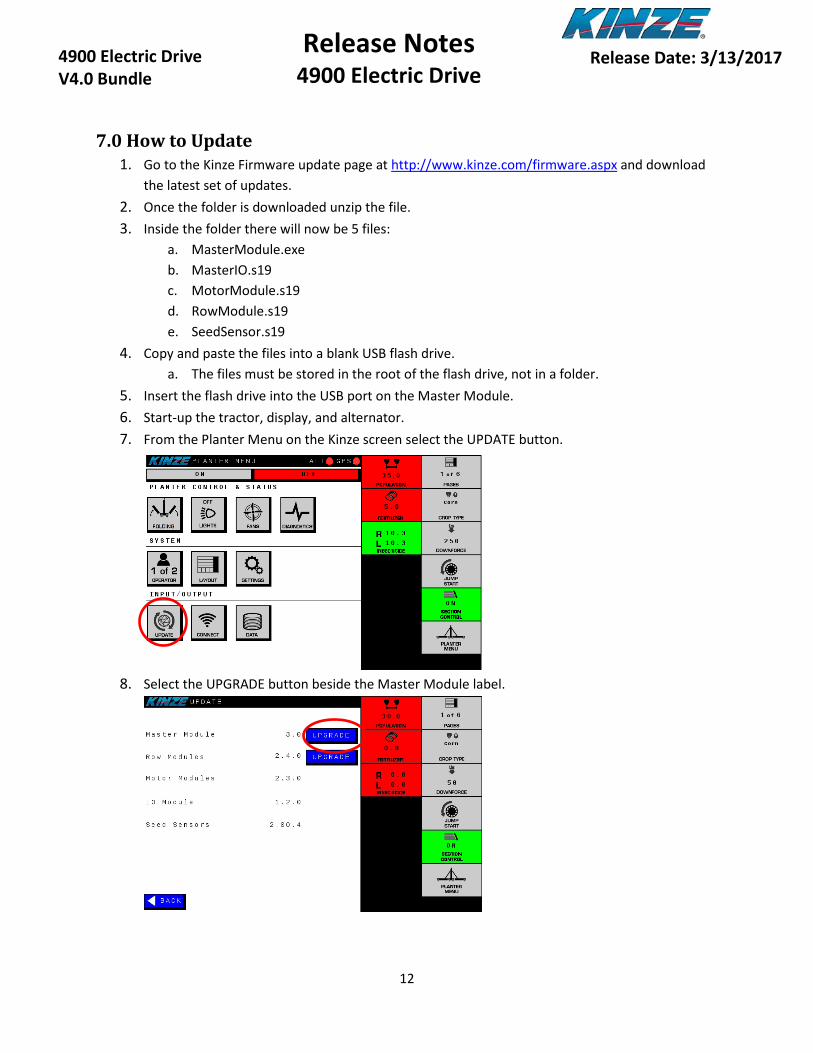
7.0 How to Update 1. Go to the Kinze Firmware update page at http://www.kinze.com/firmware.aspx and download
the latest set of updates. 2. Once the folder is downloaded unzip the file. 3. Inside the folder there will now be 5 files:
a. MasterModule.exe b. MasterIO.s19 c. MotorModule.s19 d. RowModule.s19 e. SeedSensor.s19
4. Copy and paste the files into a blank USB flash drive. a. The files must be stored in the root of the flash drive, not in a folder.
5. Insert the flash drive into the USB port on the Master Module. 6. Start-up the tractor, display, and alternator. 7. From the Planter Menu on the Kinze screen select the UPDATE button.
8. Select the UPGRADE button beside the Master Module label.
7
13
Release Notes 4900 Electric Drive
4900 Electric Drive V4.0 Bundle
Release Date: 3/13/2017
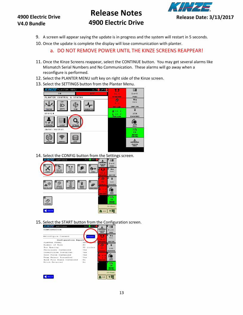
9. A screen will appear saying the update is in progress and the system will restart in 5 seconds. 10. Once the update is complete the display will lose communication with planter.
a. DO NOT REMOVE POWER UNTIL THE KINZE SCREENS REAPPEAR!
11. Once the Kinze Screens reappear, select the CONTINUE button. You may get several alarms like Mismatch Serial Numbers and No Communication. These alarms will go away when a reconfigure is performed.
12. Select the PLANTER MENU soft key on right side of the Kinze screen. 13. Select the SETTINGS button from the Planter Menu.
14. Select the CONFIG button from the Settings screen.
15. Select the START button from the Configuration screen.

7
14
Release Notes 4900 Electric Drive
4900 Electric Drive V4.0 Bundle
Release Date: 3/13/2017
16. Step through the configuration process and ensure the planter is reporting all the rows. a. If not, check the rows that do not appear for module or wiring issues.
17. Select finish when all of the rows are found in the configuration process. The Master Module will restart.
18. Once the Kinze Screens reappear, select the CONTINUE button. 19. Select the PLANTER MENU soft key on right side of the Kinze screen. 20. Navigate back to the update screen and make sure the new version is listed for the Master
Module. 21. Next the Row Modules will be updated. 22. Turn on the Alternator if it is not already on.
a. DO NOT TURN THE ALTERNATOR OFF UNTIL THE ROW MODULE UPDATE IS COMPLETE!
23. Select the Upgrade button beside the Row Modules label as seen below.
24. A screen will appear giving the update status. Each Row Module will be updated one at a time. 25. This update could take up to 10 minutes depending on planter size. 26. Once the update is complete you will be returned to the Update screen. 27. Verify that the new version is now displayed beside the Row Modules label. 28. Once updating the Row Modules is complete, turn off the alternator. 29. Then power off the display. 30. Wait for at least 5 seconds after the display powers off, and then power on the display again. 31. After the power-up process is complete, turn the alternator on again.
7
15
Release Notes 4900 Electric Drive
4900 Electric Drive V4.0 Bundle
Release Date: 3/13/2017
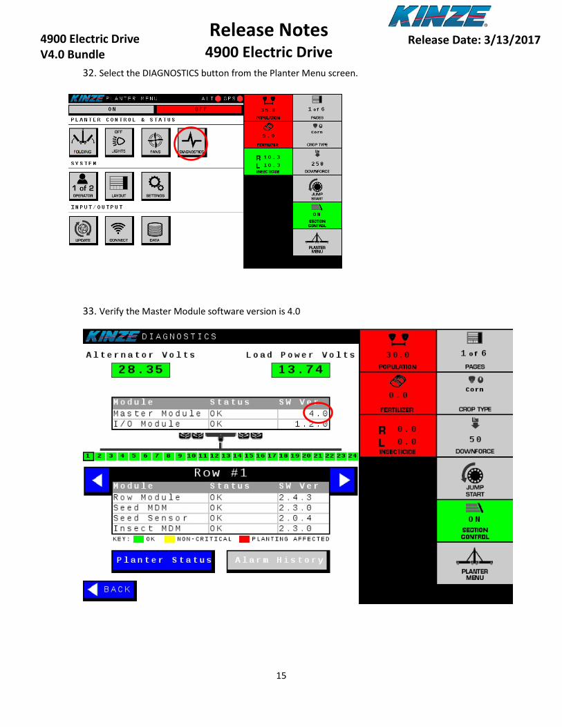
32. Select the DIAGNOSTICS button from the Planter Menu screen.
33. Verify the Master Module software version is 4.0

7
16
Release Notes 4900 Electric Drive
4900 Electric Drive V4.0 Bundle
Release Date: 3/13/2017
34. Verify that the I/O Module software version is 1.2.0

7
17
Release Notes 4900 Electric Drive
4900 Electric Drive V4.0 Bundle
Release Date: 3/13/2017
35. Verify that all rows are Green
7
18
Release Notes 4900 Electric Drive
4900 Electric Drive V4.0 Bundle
Release Date: 3/13/2017
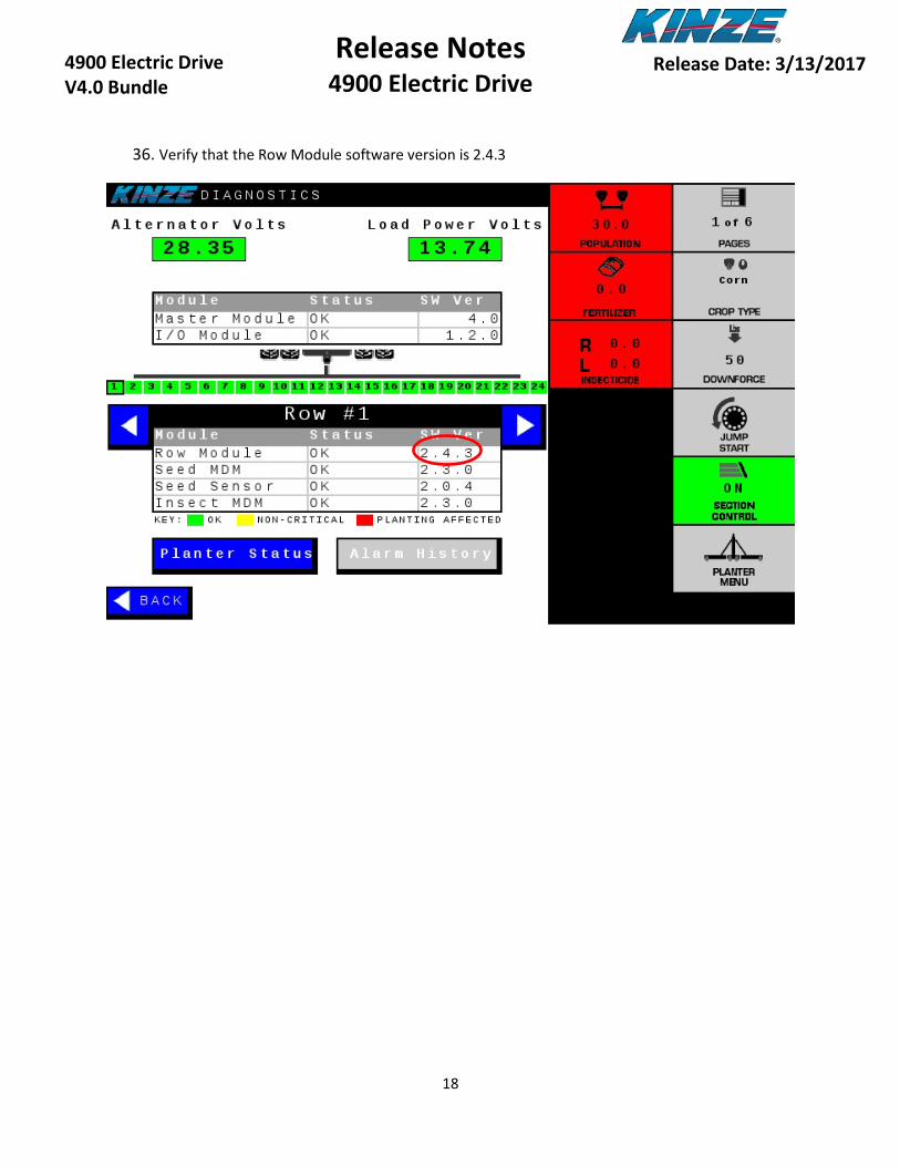
36. Verify that the Row Module software version is 2.4.3

7
19
Release Notes 4900 Electric Drive
4900 Electric Drive V4.0 Bundle
Release Date: 3/13/2017
37. Verify that the Motor Drive Module software version is 2.3.0
7
20
Release Notes 4900 Electric Drive
4900 Electric Drive V4.0 Bundle
Release Date: 3/13/2017
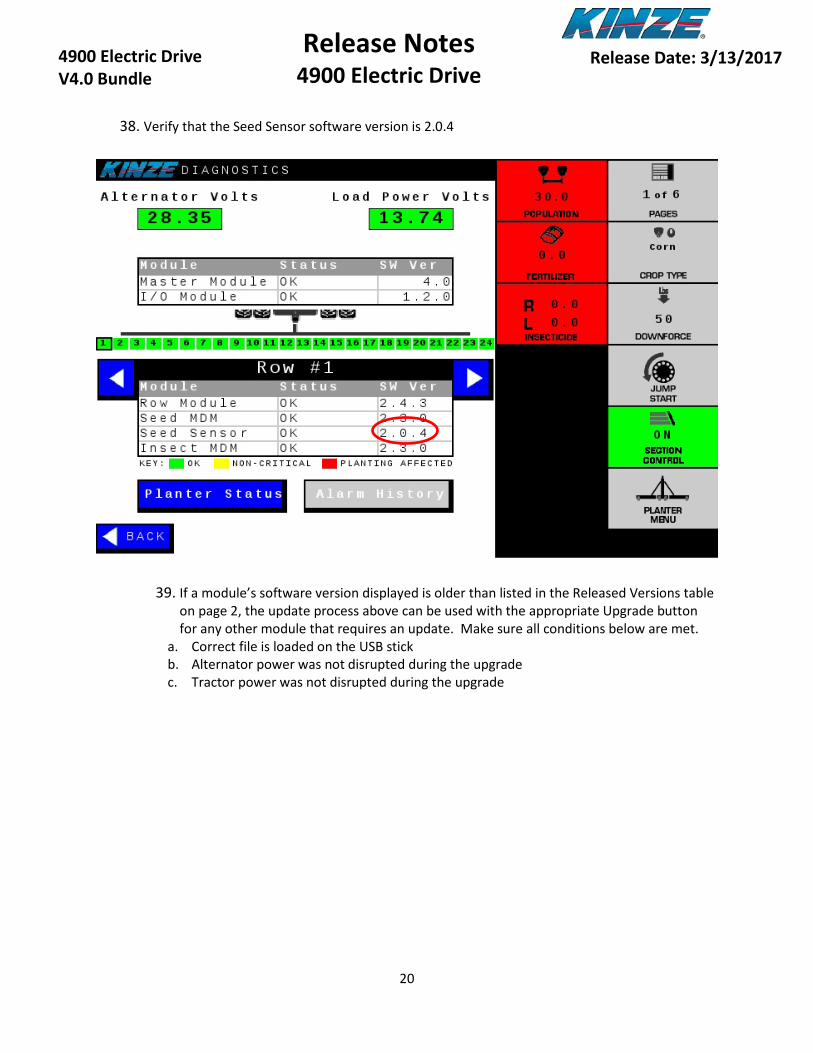
38. Verify that the Seed Sensor software version is 2.0.4
39. If a module’s software version displayed is older than listed in the Released Versions table on page 2, the update process above can be used with the appropriate Upgrade button for any other module that requires an update. Make sure all conditions below are met.
a. Correct file is loaded on the USB stick b. Alternator power was not disrupted during the upgrade c. Tractor power was not disrupted during the upgrade
7
21
Release Notes 4900 Electric Drive
4900 Electric Drive V4.0 Bundle
Release Date: 3/13/2017
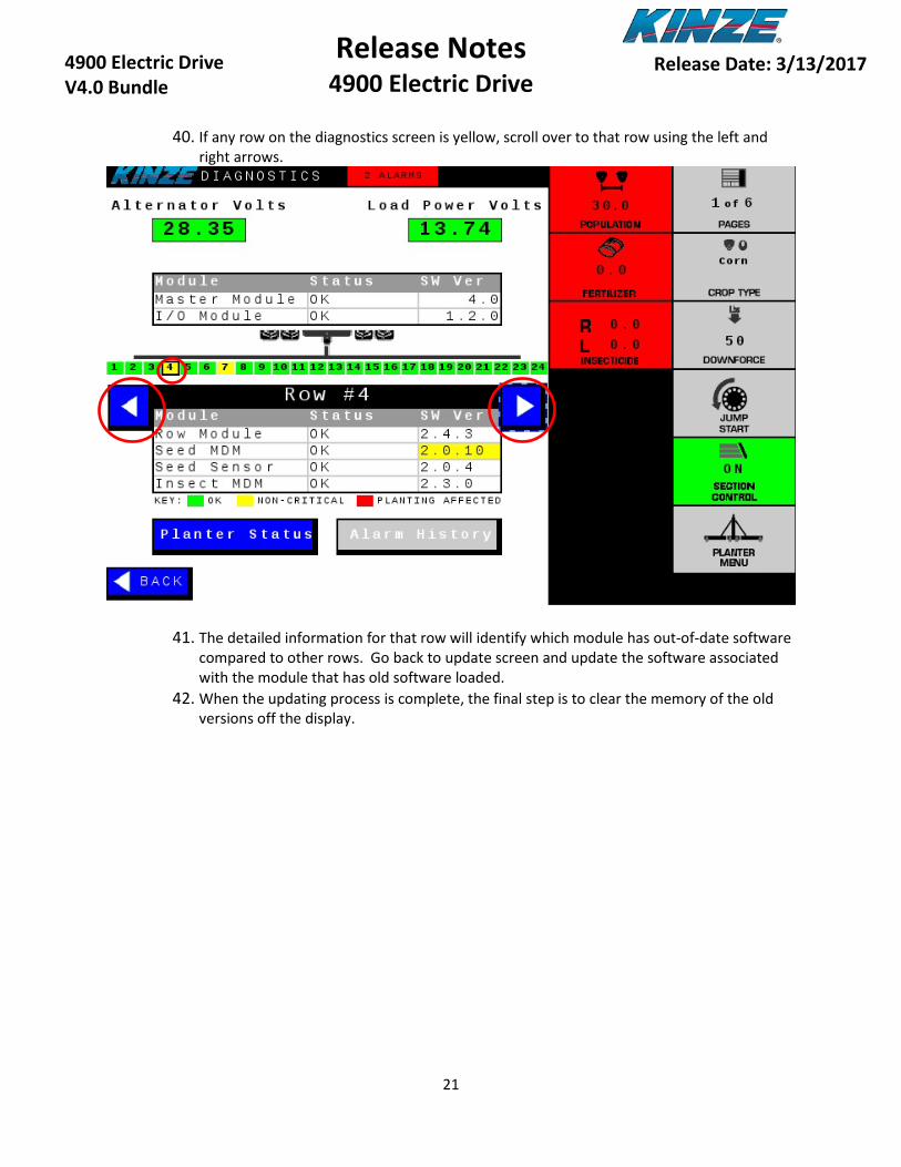
40. If any row on the diagnostics screen is yellow, scroll over to that row using the left and
right arrows.
41. The detailed information for that row will identify which module has out-of-date software compared to other rows. Go back to update screen and update the software associated with the module that has old software loaded.
42. When the updating process is complete, the final step is to clear the memory of the old versions off the display.
7
22
Release Notes 4900 Electric Drive
4900 Electric Drive V4.0 Bundle
Release Date: 3/13/2017
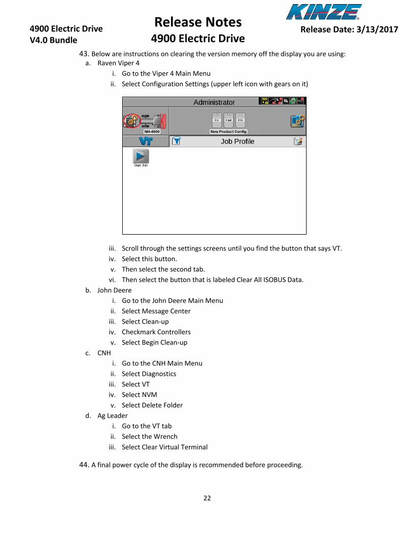
43. Below are instructions on clearing the version memory off the display you are using: a. Raven Viper 4
i. Go to the Viper 4 Main Menu ii. Select Configuration Settings (upper left icon with gears on it)
iii. Scroll through the settings screens until you find the button that says VT. iv. Select this button. v. Then select the second tab.
vi. Then select the button that is labeled Clear All ISOBUS Data. b. John Deere
i. Go to the John Deere Main Menu ii. Select Message Center
iii. Select Clean-up iv. Checkmark Controllers v. Select Begin Clean-up
c. CNH i. Go to the CNH Main Menu
ii. Select Diagnostics iii. Select VT iv. Select NVM v. Select Delete Folder
d. Ag Leader i. Go to the VT tab
ii. Select the Wrench iii. Select Clear Virtual Terminal
44. A final power cycle of the display is recommended before proceeding.

7
23
Release Notes 4900 Electric Drive
4900 Electric Drive V4.0 Bundle
Release Date: 3/13/2017
8.0 Electronics Pre-Season Check Out It is always a good idea to check your equipment before the start of the season to make sure everything is operational and ready to go to the field. Below are some checks that should be done prior to planting. To run these tests make sure the tractor, display and alternator are turned on.
1. Check to make sure your lighting is working properly. a. Left Turn b. Right Turn c. Tail Lights d. Work Lights (if installed)
2. Check to make sure your tool bar position sensors (implement switches) are operational and set
correctly. a. To do this, go to the Planter Menu and select Settings. b. Then select Tool Bar Sensing. c. This will give you a display of the states of the left and right switches. Up means the
planter is up and Down means the planter is in the ground. d. Lift and lower the planter and make sure the states change accordingly.
3. Check your vacuum fans to ensure they are operational.
a. Turn the hydraulics or PTO on for the Vacuum. b. Turn the Master Switch and Fans on. c. Go to the Planter Menu and select Settings. d. Then select Vacuum Fan Drive. e. At the bottom of the screen there is a Diagnostics Section. f. Check to see that the Actual readout on screen roughly matches the Analog gauges
mounted on the planter. g. If they do not roughly match, you may need to zero the sensor or Analog gauge.
4. Check your bulk fill fan to ensure it is operational.
a. Turn the hydraulics on for the Bulk Fill Fan. b. Turn the Master Switch and Fans on. c. Go to the Planter Menu and select Settings. d. Then select Blk Fill Fan. e. At the bottom of the screen there is a Diagnostics Section. f. Check to see that the Actual readout on screen roughly matches the Analog gauge
mounted on the planter. g. If they do not roughly match, you may need to zero the sensor or Analog gauge.
5. Check to make sure all motors on the planter spin.
a. To do this, go to the Planter Menu and select Settings. b. Then select Speed. c. Then select Manual Speed and make sure a speed is entered. d. Select back until you get to the Planter Menu.
e. Then turn on the Master Switch and set the planter down.

7
24
Release Notes 4900 Electric Drive
4900 Electric Drive V4.0 Bundle
Release Date: 3/13/2017
f. The motors for the seed meters and insecticide meters (if installed) should start spinning.
g. Go through each row one-by-one and make sure the motor on each row meter is turning.
h. Pay special attention to the insecticide motors (if installed) and make sure they are all spinning at the same speed. If one is spinning noticeably faster, this could be a wiring issue.
i. After your test is complete, make sure you go back to the Speed Settings screen and change it from Manual to your desired speed source. (Automatic Recommended)
6. Check to ensure the Seed Sensors are reading properly. a. To do this stick a seed tube brush up and down the tube and make sure the red light on
the seed sensor blinks when it sees the brush.
7. If Insecticide is installed, check to ensure the sensors are reading properly. a. To do this go to the Planter Menu and select Settings. b. Then select Insecticide. c. At the bottom of the screen there is a Diagnostics Section. d. In the row labeled VDC, each row with insecticide installed should have a voltage
reading. e. If it reads 0.0 on any such row, then there is an issue with the sensor.
8. If Fertilizer is installed, check to ensure the control system is working properly.
a. If possible, fill the tank with water; 1/8 of a tank should be enough for these tests. b. Turn hydraulics for the fertilizer pump on. c. Set the rate to 5 gal/ac. d. Turn the fertilizer and Master Switch on, then set the planter down. e. The fertilizer pump should start running. f. Go to the Planer Menu and select Settings. g. Then select Speed. h. Then select Manual Speed and make sure a speed is entered. i. Then select the Back button. j. Then select Fertilizer. k. At the bottom of the screen you will find a Diagnostics Section. l. Ensure that after 20 seconds the Actual Rate matches the Set Rate. m. Ensure that in the rows labeled FS (Flow Sensor) all say ON. If they stay OFF, that
indicates that there could be a problem with that row. n. Drain the rest of the water from the system and make sure you change the Speed
setting back to your desired speed source. (Automatic is Recommended)
9. If Pneumatic Down Force is installed, ensure it is working properly. a. Ensure that the compressor kicks on when the tank is below 60 psi. b. Ensure that once the Master Switch is turned on it adjusts to the correct force. c. Check the planter for leaks.

7
25
Release Notes 4900 Electric Drive
4900 Electric Drive V4.0 Bundle
Release Date: 3/13/2017
10. If Bulk Fill Scales are installed, ensure they are working properly.
a. Ensure that both the right and left tanks are reading on both the Remote Display (located on the catwalk) and in the cab.
11. Check the Jump Start sensor for damage and proper adjustment. a. Inspect the wiring going from the Jump Start sensor to the Master Module for damage.
If damaged, repair it; or if you choose not to use the sensor, ensure the wires are taped up out of the way where they will not touch any steel or each other.
b. Inspect the sensor position to the pick-up wheel. The gap should be between 1/8” and 1/4”. Turn the tire one full revolution and make sure that the sensor does not touch the pick-up wheel.
7
26
Release Notes 4900 Electric Drive
4900 Electric Drive V4.0 Bundle
Release Date: 3/13/2017
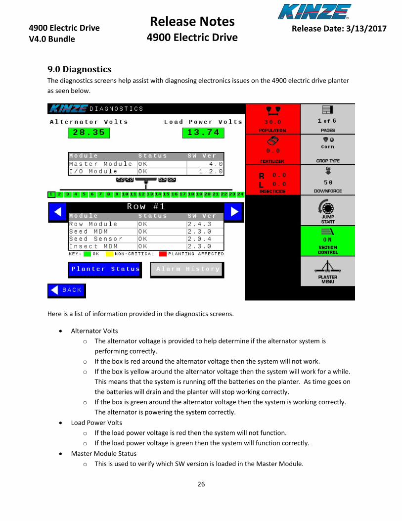
9.0 Diagnostics The diagnostics screens help assist with diagnosing electronics issues on the 4900 electric drive planter as seen below.
Here is a list of information provided in the diagnostics screens.
• Alternator Volts o The alternator voltage is provided to help determine if the alternator system is
performing correctly. o If the box is red around the alternator voltage then the system will not work. o If the box is yellow around the alternator voltage then the system will work for a while.
This means that the system is running off the batteries on the planter. As time goes on the batteries will drain and the planter will stop working correctly.
o If the box is green around the alternator voltage then the system is working correctly. The alternator is powering the system correctly.
• Load Power Volts o If the load power voltage is red then the system will not function. o If the load power voltage is green then the system will function correctly.
• Master Module Status o This is used to verify which SW version is loaded in the Master Module.
7
27
Release Notes 4900 Electric Drive
4900 Electric Drive V4.0 Bundle
Release Date: 3/13/2017
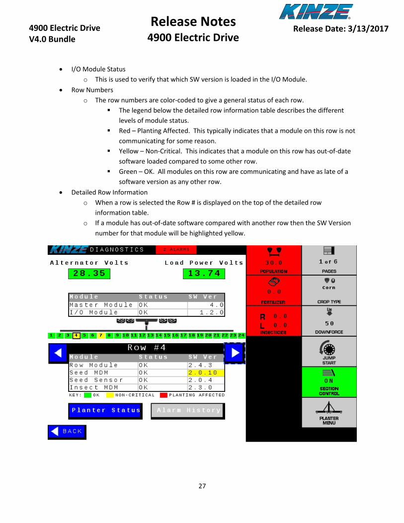
• I/O Module Status o This is used to verify that which SW version is loaded in the I/O Module.
• Row Numbers o The row numbers are color-coded to give a general status of each row.
The legend below the detailed row information table describes the different levels of module status.
Red – Planting Affected. This typically indicates that a module on this row is not communicating for some reason.
Yellow – Non-Critical. This indicates that a module on this row has out-of-date software loaded compared to some other row.
Green – OK. All modules on this row are communicating and have as late of a software version as any other row.
• Detailed Row Information o When a row is selected the Row # is displayed on the top of the detailed row
information table. o If a module has out-of-date software compared with another row then the SW Version
number for that module will be highlighted yellow.

7
28
Release Notes 4900 Electric Drive
4900 Electric Drive V4.0 Bundle
Release Date: 3/13/2017
o If a module is not communicating then the Status column for that module will be highlighted red with the text “Missing” and the SW Version column will have “???” to indicate that the Master Module is not able to receive responses from that module. Cycling the alternator off and back on may restore communications with a single module.
7
29
Release Notes 4900 Electric Drive
4900 Electric Drive V4.0 Bundle
Release Date: 3/13/2017
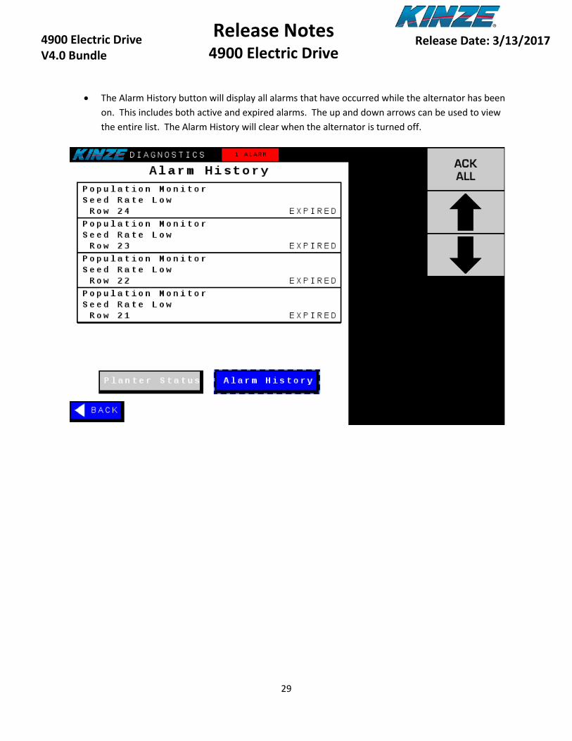
• The Alarm History button will display all alarms that have occurred while the alternator has been on. This includes both active and expired alarms. The up and down arrows can be used to view the entire list. The Alarm History will clear when the alternator is turned off.