Embed Size (px)
Citation preview

Relevance of Geophysics in Road Failures Investigation in a Typical Basement Complex of Southwestern Nigeria.
K.A.N. Adiat, M.Tech.*, A.O. Adelusi, Ph.D., and M.A. Ayuk, M.Tech.
Department of Applied Geophysics, Federal University of Technology,
PMB 704, Akure, Nigeria.
*E-mail: [email protected]
ABSTRACT Electrical resistivity and electromagnetic methods were used in evaluating the subsurface integrity of a 3 km stretch of road from Igbara-Oke to Ibuji in southwestern Nigeria. A 3km Igbara-Oke-Ibuji road was geophysically investigated using Very Low Frequency Electromagnetic (VLF-EM) profiling and lateral resistivity profiling both at 10m intervals and twenty-one Schlumberger Vertical Electrical Sounding (VES). The results from the VLF-EM study showed presence of near surface linear geologic structures of varying lengths, depths, and attitude which suggest probable conductive zones that are inimical to the foundation of the road subgrade. Also, the lateral resistivity profile showed low resistivity zones that coincide with most of the peak positive VLF-EM anomaly showing near surface clay materials and linear structures. The quantitative interpretation of the VES results established the presence of four geologic layers which are: top soil, sand/lateritic sand, weathered basement, and basement with layers resistivity and thickness varying respectively from 88-553 Ωm, 253-507 Ωm, 63-308 Ωm, 994-12208 Ωm and 0.5-1.6 m, 2.4-2.6 m, 2.5-20.5 m, infinity. The unstable segment of the road is characterized by low resistivity of the near surface materials and shallowness of the aquiferrous zone on which the road pavement was founded. Furthermore, the failure of the road is controlled mainly by geologic sequence and structures. The study further stressed the importance and relevance of geophysics in evaluating civil engineering structure such as roads.
(Keywords: geophysics, road subsurface, civil engineering, road engineering, road failure)
INTRODUCTION Incessant failure of highways has become a common phenomenon in many parts of Nigeria. The problem is apparently on the cut out section of roadways within the Precambrian basement complex terrain of the country. The present condition of most of the roads in the Precambrian basement complex of south western Nigeria has stimulated the interest of various stakeholders in the usage and maintenance of our road ways. Rehabilitating the road ways has become a financial burden on the Federal, State, and Local Governments, hence there is need to identify the causes of road failure and find a means of ameliorating the problem. Several factors are responsible for road failures, which include geological, geomorphological, geotechnical, road usage, construction practices, and maintenance (Adegoke–Anthony and Agada, 1980; Ajayi, 1987). Field observations and laboratory experiments carried out by Adegoke–Anthony and Agada (1980), Mesida (1981), and Ajayi (1987) showed that road failures are not primarily due to usage or design construction problems alone but can equally arise from inadequate knowledge of the characteristics and behavior of residual soils on which the road are built and non-recognition of the influence of geology and geomorphology during the design and construction phases. The geological factors influencing road failures include the nature of soils (laterites) and the near surface geologic sequence, existence of geological structures such as fractures and faults, presences of laterites, existence of ancient stream channels, and shear zones. The collapse of concealed subsurface geological structures and other zones of weakness controlled by regional fractures and joint systems along with silica leaching which has led to rock deficiency
The Pacific Journal of Science and Technology –528– http://www.akamaiuniversity.us/PJST.htm Volume 10. Number 1. May 2009 (Spring)
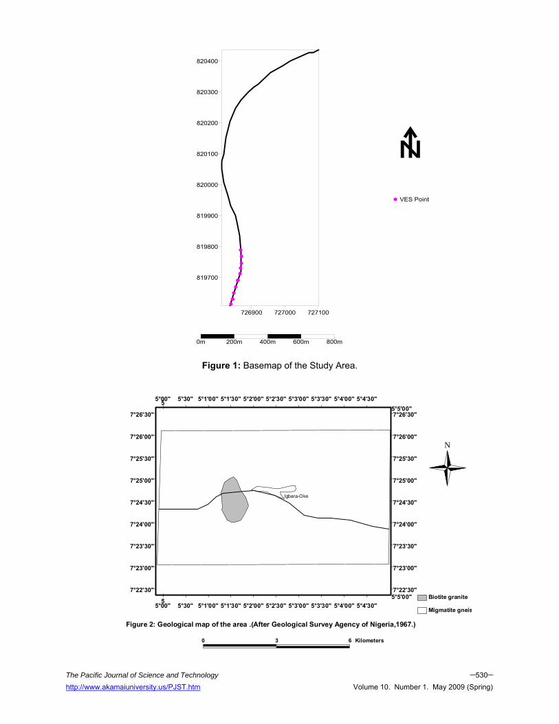
are known to contribute to failures of highways and rail tracks (Nelson and Haigh, 1990). The geomorphological factors are related to topography and surface/subsurface drainage system. For the past two decades, geophysics has proved quite relevant in highway site investigations (Nelson and Haigh, 1990), geophysical methods like electrical resistivity has been used in mapping subsurface geologic sequence and concealed geological structures (Olorunfemi et al., 2004). Even the electromagnetic prospecting method has been used also in high way investigation along Akure-Ilesha road southwestern Nigeria (Akintorinwa et al., 2008) including geophysical investigation of Ilesha-Owena highway failure in the basement complex area of southwestern Nigeria (Momoh et al 2007). In the present study, geophysical investigation of causes and characteristics of road failure in Igbara-Oke–Ibuji, a basement complex area, has been carried out. GEOLOGY OF THE STUDY AREA The study area falls within the basement complex of southwestern Nigeria. The area falls within easting 0726836 (5° 3΄ 18.39΄΄ E) to 0727120 (5° 3΄ 27.77΄΄ E) and northing 0819608 (7° 24΄ 38.76΄΄ N) to 0820447 (7° 25΄ 6.02΄΄ N).The rock types in the area are low-lying undifferentiated migmatite gneiss and biotite granite (Figure 2 and 3). SITE DESCRIPTION Igbara-Oke is about 10km from Akure; however, the study area covered about 3km from Igbara-Oke end of Igbara-Oke-Ibuji road. The first 500m from Igbara-Oke end represents the stable segment of the road. The elevation above sea level ranges from 357m to 370m (Figure 1). The regional soils belong to the Ondo Association. GEOPHYSICAL SURVEYS Geophysical investigation involving the integration of Very Low Frequency Electromagnetic (VLF – EM) and Electrical Resistivity methods were carried out along both the failed and stable segments of the road. A traverse of about 3000m (3km) length was established parallel to the road pavement. ABEM WADI was used for the VLF –
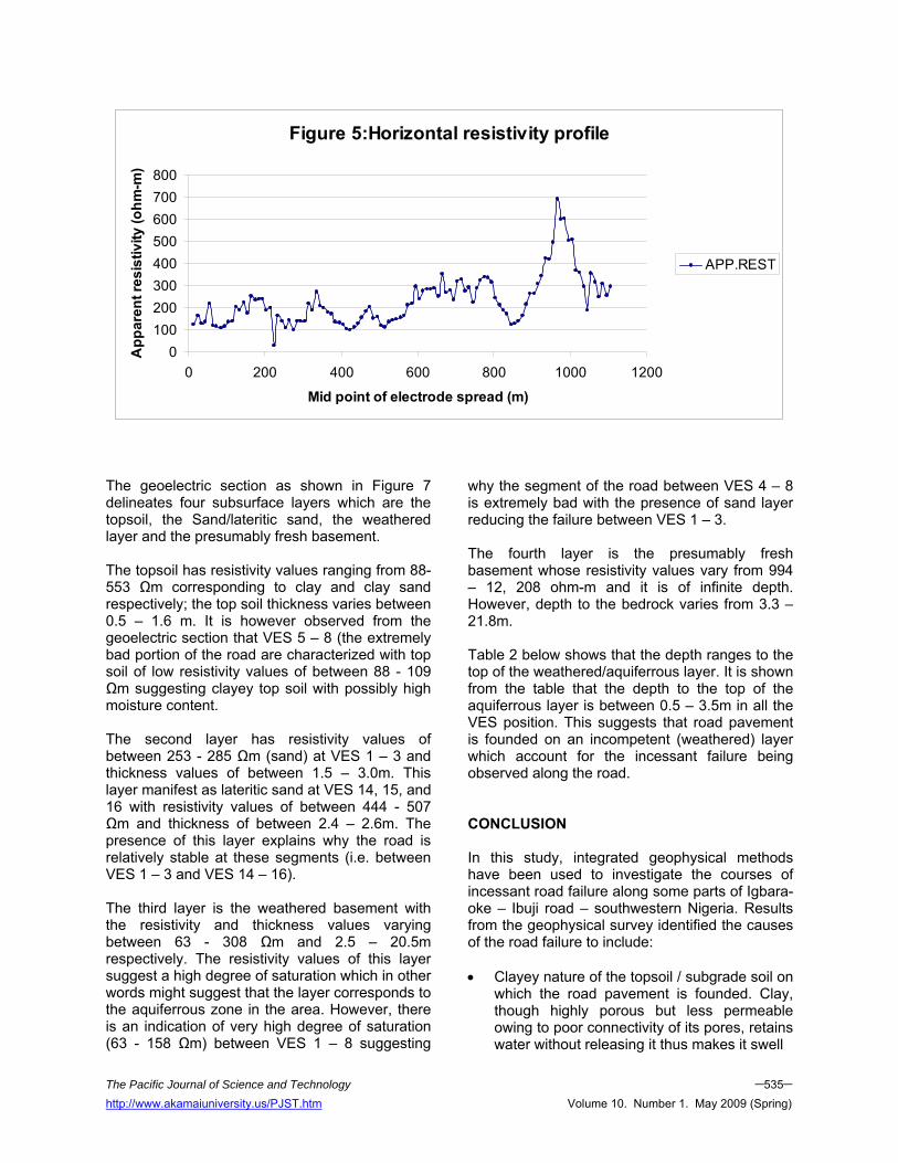
EM data collection along the road segment. The VLF transmitter operating at frequency of 17.6 KHz and located in Oxford, Great Britain was used for the investigation. The station to station interval of 10m was adopted for the survey. The Electrical Resistivity method utilized Horizontal Profiling (HP) and Vertical Electrical Sounding (VES). Horizontal Profiling was carried out to know the lateral variation in ground apparent resistivity. Wenner electrode array configuration with electrode separation (a) of 10m was adopted for the horizontal profiling. The VES on the other hand entailed 1-D vertical probing of the subsurface. Owing to logistic problems, the VES investigation was restricted to the first 1050m portion of the investigated road and it was carried out at regular interval of 50m. The VES utilized Schlumberger electrode array configuration with maximum electrode separation (AB) of 200m. RD – 50 Resistivity meter was used for the resistivity investigation. The HP was presented as profile where in the apparent resistivity values are plotted against the mid point of electrode spread (i.e. AB/2) on linear graph (Figure 5) and this was qualitatively interpreted. The VLF-EM results were presented both as profiles (i.e. plot of raw real and filtered real against station) and as inverted pseudosections obtained by using KHFILT software. (Figures 4a-c). The VES curves were interpreted quantitatively by partial curve matching and computer iteration technique using RESIST Software. The interpretation results were presented as sounding curves and geoelectric section (Figures 6 and 7, respectively). RESULTS AND DISCUSSION The VLF-EM Profiles The plot of Raw Real (RR) and Filtered Real (FR) plotted against station distances is shown as profile. However, for clear and easy interpretation, the profile was presented in three segments shown in Figures 4a, 4b and 4c.The interpretation of this profile is mere qualitative and this involves visual inspection of the profile for points where the maximum peak of the Filtered Real coincides with the point of inflections of raw real as such
The Pacific Journal of Science and Technology –529– http://www.akamaiuniversity.us/PJST.htm Volume 10. Number 1. May 2009 (Spring)
The Pacific Journal of Science and Technology –530– http://www.akamaiuniversity.us/PJST.htm Volume 10. Number 1. May 2009 (Spring)
726900 727000 727100
819700
819800
819900
820000
820100
820200
820300
820400
0m 200m 400m 600m 800m
VES Point
Igbara-Oke
0 3 6 Kilometers
N
Figure 2: Geological map of the area .(After Geological Survey Agency of Nigeria,1967.)
Migmatite gneis
Biotite granite7°22'30" 7°22'30"
7°23'00" 7°23'00"
7°23'30" 7°23'30"
7°24'00" 7°24'00"
7°24'30" 7°24'30"
7°25'00" 7°25'00"
7°25'30" 7°25'30"
7°26'00" 7°26'00"
7°26'30" 7°26'30"
5°00"
5°00"
5°30"
5°30"
5°1'00"
5°1'00"
5°1'30"
5°1'30"
5°2'00"
5°2'00"
5°2'30"
5°2'30"
5°3'00"
5°3'00"
5°3'30"
5°3'30"
5°4'00"
5°4'00"
5°4'30"
5°4'30"
5°5'00"
5°5'00"5
5
Figure 1: Basemap of the Study Area.

The Pacific Journal of Science and Technology –531– http://www.akamaiuniversity.us/PJST.htm Volume 10. Number 1. May 2009 (Spring)
#
# #
#
#
#
#
Igbara-Oke
Ibuji
Study Area
Ch
Sch Sch
Sch
Sch
Ch
Ala-Owena
1150
1050
0 4 8 Kilometers
N
Figure 3: Topographical m ap of the area
7°24'00" 7°24'00"
7°25'30" 7°25'30"
7°27'00" 7°27'00"
5°00'00"
5°00'00"
5°1'30"
5°1'30"
5°3'00"
5°3'00"
5°4'30"
5°4'30"5
5
points are usually suggestive of presence of conductive (weak) zones. Several of such points were identified on the profiles; furthermore, the presence of multiple peak Positive filtered real anomalies (as observed on the profiles) is suggestive of inhomogeneity of near surface material. The corresponding 2 – D models of the filtered real for each segment of the profile are as shown in figures 4a to 4c. The model shows that the study area is characterized with presence of linear features of different azimuthal direction (SE-NW, SW – NE etc) and of different conductivity ranges. The presence of these near surfaces cross cutting linear structures is indicative of weak/incompetent geologic formation upon which the road pavement was founded which consequently accounts for its failure. The horizontal resistivity profile (HRP) The plot of apparent resistivity against midpoint of the total electrode spread (i.e.AB/2) for each
measurement is presented as profile shown in Figure 5. The qualitative interpretation of the profile involves mere inspection of the profile for presence of low apparent resistivity as such points are indicative of conductive (weak) zones. The apparent resistivity values vary between 27 and 694 ohm-m. The presence of series of resistivity lows and highs observed on the profile is indicative of either lateral inhomogeneity in the geologic material underlay the road segment or presence of near surface features such as lineaments, fractures, joints, shear zones or clay etc. Resistivity Sounding Curves and Geoelectric Sections Three resistivity sounding curve types were obtained from the surveyed area and these are the H, A and KH types with percentage frequency of occurrence of 52.38, 14.29 and 33.33% respectively. The results of the interpreted VES Curves are shown in table1 below while typical Curve types obtained from the area are shown in Figure 6.

The Pacific Journal of Science and Technology –532– http://www.akamaiuniversity.us/PJST.htm Volume 10. Number 1. May 2009 (Spring)
Figure 4a:VLF profile for Segment 1 and Corresponding KH Section
-80
-60
-40
-20
0
20
40
60
0 200 400 600 800 1000 1200
Distances (m)
RR
/FR RR
FR
0 100 200 300 400 500 600 700 800 900Distance (m)
-100
-50
Dep
th (
m)
Karous-Hjelt filtering"IGBARA-OKE-IBUJI RD SEGMENT!"
-40 -20 0 20 40Real component, unnormalized

The Pacific Journal of Science and Technology –533– http://www.akamaiuniversity.us/PJST.htm Volume 10. Number 1. May 2009 (Spring)
Figure 4b: VLF profile for Segment 2 and Corresponding KH Section
-15
-10
-5
0
5
10
1010 1260 1510 1760
Distances (m)
RR
/FR RRFR
1100 1200 1300 1400 1500 1600 1700 1800 1900 2000Distance (m)
-100
-50
Dep
th (
m)
Karous-Hjelt filtering"IGBARA-OKE-IBUJI RD SEGMENT 2
-40 -20 0 20 40Real component, unnormalized

The Pacific Journal of Science and Technology –534– http://www.akamaiuniversity.us/PJST.htm Volume 10. Number 1. May 2009 (Spring)
Figure 4c:VLF profile for Segment 3 and Corresponding KH Section
-50-40-30-20-10
0102030405060
2000 2200 2400 2600 2800 3000
Distances (m)
RR
/FR RRFR
2200 2400 2600 2800 3000Distance (m)
-100
-50
Dep
th (
m)
Karous-Hjelt filtering"IGBARA-OKE-IBUJI RD SEGMENT 3
-40 -20 0 20 40Real component, unnormalized
The Pacific Journal of Science and Technology –535– http://www.akamaiuniversity.us/PJST.htm Volume 10. Number 1. May 2009 (Spring)
Figure 5:Horizontal resistivity profile
0100200300400500600700800
0 200 400 600 800 1000 1200
Mid point of electrode spread (m)
App
aren
t res
istiv
ity (o
hm-m
)
APP.REST
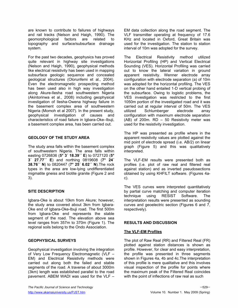
The geoelectric section as shown in Figure 7 delineates four subsurface layers which are the topsoil, the Sand/lateritic sand, the weathered layer and the presumably fresh basement. The topsoil has resistivity values ranging from 88-553 Ωm corresponding to clay and clay sand respectively; the top soil thickness varies between 0.5 – 1.6 m. It is however observed from the geoelectric section that VES 5 – 8 (the extremely bad portion of the road are characterized with top soil of low resistivity values of between 88 - 109 Ωm suggesting clayey top soil with possibly high moisture content. The second layer has resistivity values of between 253 - 285 Ωm (sand) at VES 1 – 3 and thickness values of between 1.5 – 3.0m. This layer manifest as lateritic sand at VES 14, 15, and 16 with resistivity values of between 444 - 507 Ωm and thickness of between 2.4 – 2.6m. The presence of this layer explains why the road is relatively stable at these segments (i.e. between VES 1 – 3 and VES 14 – 16). The third layer is the weathered basement with the resistivity and thickness values varying between 63 - 308 Ωm and 2.5 – 20.5m respectively. The resistivity values of this layer suggest a high degree of saturation which in other words might suggest that the layer corresponds to the aquiferrous zone in the area. However, there is an indication of very high degree of saturation (63 - 158 Ωm) between VES 1 – 8 suggesting
why the segment of the road between VES 4 – 8 is extremely bad with the presence of sand layer reducing the failure between VES 1 – 3. The fourth layer is the presumably fresh basement whose resistivity values vary from 994 – 12, 208 ohm-m and it is of infinite depth. However, depth to the bedrock varies from 3.3 – 21.8m. Table 2 below shows that the depth ranges to the top of the weathered/aquiferrous layer. It is shown from the table that the depth to the top of the aquiferrous layer is between 0.5 – 3.5m in all the VES position. This suggests that road pavement is founded on an incompetent (weathered) layer which account for the incessant failure being observed along the road. CONCLUSION In this study, integrated geophysical methods have been used to investigate the courses of incessant road failure along some parts of Igbara-oke – Ibuji road – southwestern Nigeria. Results from the geophysical survey identified the causes of the road failure to include: • Clayey nature of the topsoil / subgrade soil on
which the road pavement is founded. Clay, though highly porous but less permeable owing to poor connectivity of its pores, retains water without releasing it thus makes it swell
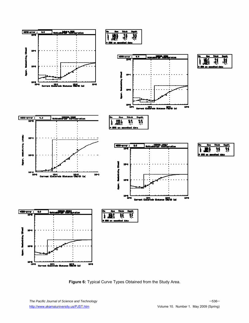
Figure 6: Typical Curve Types Obtained from the Study Area.
The Pacific Journal of Science and Technology –536– http://www.akamaiuniversity.us/PJST.htm Volume 10. Number 1. May 2009 (Spring)

Table 1: The Results of the Interpreted VES Curves. VES
NUMBER THICKNESS(M) LAYER RESISTIVITY(ΩM) REMARKS CURVE
TYPES NUMBER
0F LAYERS
0.6 143 TOP SOIL(CLAYEY SAND) 1.9 280 WEATHERED LAYER
12.4 147 FRACTURED BEDROCK 1
1731 FRESH BEDROCK
KH 4
0.6 137 TOP SOIL(CLAYEY SAND) 1.9 284 WEATHERED LAYER
12.4 145 FRACTURED BEDROCK 2
1792 FRESH BEDROCK
KH 4
0.5 141 TOP SOIL(CLAYEY SAND) 3.1 253 WEATHERED LAYER 8.6 112 FRACTURED BEDROCK 3
994 FRESH BEDROCK
KH 4
0.7 140 TOP SOIL(CLAYEY SAND) 0.8 383 WEATHERED LAYER
18.2 158 FRACTURED BEDROCK 4
1900 FRESH BEDROCK
KH 4
0.9 109 TOP SOIL(SANDY CLAY) 5.4 125 WEATHERED LAYER 5 7944 FRESH BEDROCK
A 3
0.6 93 TOP SOIL( CLAY) 3.9 106 WEATHERED LAYER 6 7280 FRESH BEDROCK
A 3
0.8 103 TOP SOIL(SANDY CLAY) 2.5 63 WEATHERED LAYER 7 9181 FRESH BEDROCK
H 3
0.5 88 TOP SOIL( CLAY) 3.9 96 WEATHERED LAYER 8 4355 FRESH BEDROCK
A 3
0.5 359 TOP SOIL(SAND FORMATION) 5.6 201 WEATHERED LAYER 9 2378 FRESH BEDROCK
H 3
1.6 547 TOP SOIL(SAND FORMATION) 17.2 226 WEATHERED LAYER 10
2256 FRESH BEDROCK H 3
0.8 344 TOP SOIL(SAND FORMATION) 9.6 284 WEATHERED LAYER 11 3625 FRESH BEDROCK
H 3
0.8 355 TOP SOIL(SAND FORMATION) 9.9 292 WEATHERED LAYER 12 6697 FRESH BEDROCK
H 3
0.7 349 TOP SOIL(SAND FORMATION) 11.6 283 WEATHERED LAYER 13
12208 FRESH BEDROCK H 3
0.6 231 TOP SOIL(SAND FORMATION) 2.6 444 WEATHERED LAYER
14.5 134 FRACTURED BEDROCK 14
4218 FRESH BEDROCK
KH 4
0.6 240 TOP SOIL(SAND FORMATION) 2.5 472 WEATHERED LAYER
14.5 148 FRACTURED BEDROCK 15
5177 FRESH BEDROCK
KH 4
0.7 221 TOP SOIL(SAND FORMATION) 2.4 507 WEATHERED LAYER 8.8 122 FRACTURED BEDROCK 16
2775 FRESH BEDROCK
KH 4
The Pacific Journal of Science and Technology –537– http://www.akamaiuniversity.us/PJST.htm Volume 10. Number 1. May 2009 (Spring)

The Pacific Journal of Science and Technology –538– http://www.akamaiuniversity.us/PJST.htm Volume 10. Number 1. May 2009 (Spring)
360
355
350
345
340
335
Elev
atio
n (m
)
50m
5m
Top soilSand/lateritic sand Weathered basementFresh basement
280 284
253444
472507
143 137
141109
93140
103 88
359547
344355
349 231
240221 482
506
472 546553
V1 V2 V3 V4 V5 V6 V7 V8 V9 V10 V11 V12 V13 V14 V15 V16 V17 V18 V19 V20 V21
147
145
112
158
125106
63
96
201
226
284292
283
134
148 122298 308
275
190
247
1731 1792
994
1900
79447280
9181 4355
2378
2256 3625
6697
12208
4218
5177
27752286
3173
2466
3421
4949
0.6 482 TOP SOIL(SAND FORMATION) 4.3 298 WEATHERED LAYER 17 2286 FRESH BEDROCK
H 3
0.6 506 TOP SOIL(SAND FORMATION) 4.9 308 WEATHERED LAYER 18 3173 FRESH BEDROCK
H 3
0.7 472 TOP SOIL(SAND FORMATION) 3.9 275 WEATHERED LAYER 19 2466 FRESH BEDROCK
H 3
1.6 546 TOP SOIL(SAND FORMATION) 19 190 WEATHERED LAYER 20 3421 FRESH BEDROCK
H 3
1.3 553 TOP SOIL(SAND FORMATION) 20.5 247 WEATHERED LAYER 21
4949 FRESH BEDROCK H 3
Figure 7: Geoelectric Section along the Investigated Road.
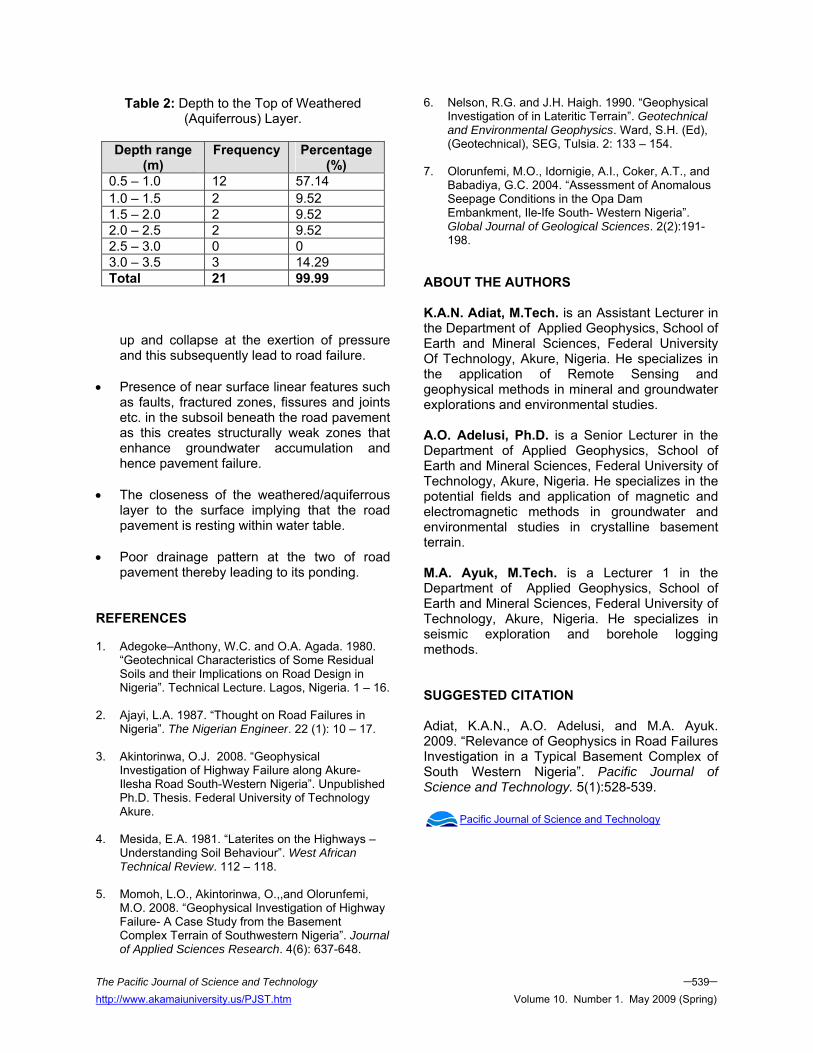
Table 2: Depth to the Top of Weathered (Aquiferrous) Layer.
Depth range
(m) Frequency Percentage
(%) 0.5 – 1.0 12 57.14 1.0 – 1.5 2 9.52 1.5 – 2.0 2 9.52 2.0 – 2.5 2 9.52 2.5 – 3.0 0 0 3.0 – 3.5 3 14.29 Total 21 99.99
up and collapse at the exertion of pressure and this subsequently lead to road failure.
• Presence of near surface linear features such as faults, fractured zones, fissures and joints etc. in the subsoil beneath the road pavement as this creates structurally weak zones that enhance groundwater accumulation and hence pavement failure.
• The closeness of the weathered/aquiferrous
layer to the surface implying that the road pavement is resting within water table.
• Poor drainage pattern at the two of road
pavement thereby leading to its ponding. REFERENCES 1. Adegoke–Anthony, W.C. and O.A. Agada. 1980.
“Geotechnical Characteristics of Some Residual Soils and their Implications on Road Design in Nigeria”. Technical Lecture. Lagos, Nigeria. 1 – 16.
2. Ajayi, L.A. 1987. “Thought on Road Failures in
Nigeria”. The Nigerian Engineer. 22 (1): 10 – 17. 3. Akintorinwa, O.J. 2008. “Geophysical
Investigation of Highway Failure along Akure-Ilesha Road South-Western Nigeria”. Unpublished Ph.D. Thesis. Federal University of Technology Akure.
4. Mesida, E.A. 1981. “Laterites on the Highways –
Understanding Soil Behaviour”. West African Technical Review. 112 – 118.
5. Momoh, L.O., Akintorinwa, O.,,and Olorunfemi,
M.O. 2008. “Geophysical Investigation of Highway Failure- A Case Study from the Basement Complex Terrain of Southwestern Nigeria”. Journal of Applied Sciences Research. 4(6): 637-648.
6. Nelson, R.G. and J.H. Haigh. 1990. “Geophysical Investigation of in Lateritic Terrain”. Geotechnical and Environmental Geophysics. Ward, S.H. (Ed), (Geotechnical), SEG, Tulsia. 2: 133 – 154.
7. Olorunfemi, M.O., Idornigie, A.I., Coker, A.T., and
Babadiya, G.C. 2004. “Assessment of Anomalous Seepage Conditions in the Opa Dam Embankment, Ile-Ife South- Western Nigeria”. Global Journal of Geological Sciences. 2(2):191-198.
ABOUT THE AUTHORS K.A.N. Adiat, M.Tech. is an Assistant Lecturer in the Department of Applied Geophysics, School of Earth and Mineral Sciences, Federal University Of Technology, Akure, Nigeria. He specializes in the application of Remote Sensing and geophysical methods in mineral and groundwater explorations and environmental studies. A.O. Adelusi, Ph.D. is a Senior Lecturer in the Department of Applied Geophysics, School of Earth and Mineral Sciences, Federal University of Technology, Akure, Nigeria. He specializes in the potential fields and application of magnetic and electromagnetic methods in groundwater and environmental studies in crystalline basement terrain. M.A. Ayuk, M.Tech. is a Lecturer 1 in the Department of Applied Geophysics, School of Earth and Mineral Sciences, Federal University of Technology, Akure, Nigeria. He specializes in seismic exploration and borehole logging methods. SUGGESTED CITATION Adiat, K.A.N., A.O. Adelusi, and M.A. Ayuk. 2009. “Relevance of Geophysics in Road Failures Investigation in a Typical Basement Complex of South Western Nigeria”. Pacific Journal of Science and Technology. 5(1):528-539.
Pacific Journal of Science and Technology
The Pacific Journal of Science and Technology –539– http://www.akamaiuniversity.us/PJST.htm Volume 10. Number 1. May 2009 (Spring)