Embed Size (px)
Citation preview
Alexander Otto
Page 1
Fraunhofer ENAS
Micro Materials Center
Reliability of New SiC BJT Power Modules for Fully Electric Vehicles
Alexander Otto1, Eberhard Kaulfersch2, Klas Brinkfeldt3, Klaus Neumaier4, Olaf Zschieschang4, Dag Andersson3, Sven Rzepka1
18th International Forum on Advanced Microsystems for Automotive Applications (AMAA 2014)
Berlin, 24. June 2014
Micro Mater ials Center
Prof. B. Michel, Prof. S. Rzepka
[email protected] Materials Center, Fraunhofer ENAS
Technologie-Campus 3, 09126 Chemnitz, Germany
1Fraunhofer ENAS2Nanotest und Design GmbH3Swerea IVF AB4Fairchild Semiconductor GmbH
Alexander Otto
Page 2
Fraunhofer ENAS
Micro Materials Center
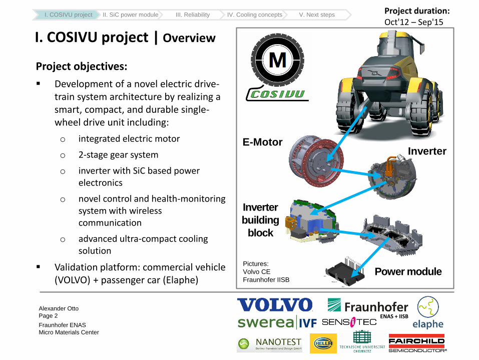
I. COSIVU project | Overview
Project objectives:
Development of a novel electric drive-train system architecture by realizing a smart, compact, and durable single-wheel drive unit including:
o integrated electric motor
o 2-stage gear system
o inverter with SiC based power electronics
o novel control and health-monitoring system with wireless communication
o advanced ultra-compact cooling solution
Validation platform: commercial vehicle (VOLVO) + passenger car (Elaphe)
E-MotorInverter
Inverter
building
block
Power modulePictures:
Volvo CE
Fraunhofer IISB
ENAS + IISB
I. COSIVU project II. SiC power module III. Reliability IV. Cooling concepts V. Next stepsProject duration:Oct'12 – Sep'15
Alexander Otto
Page 3
Fraunhofer ENAS
Micro Materials Center
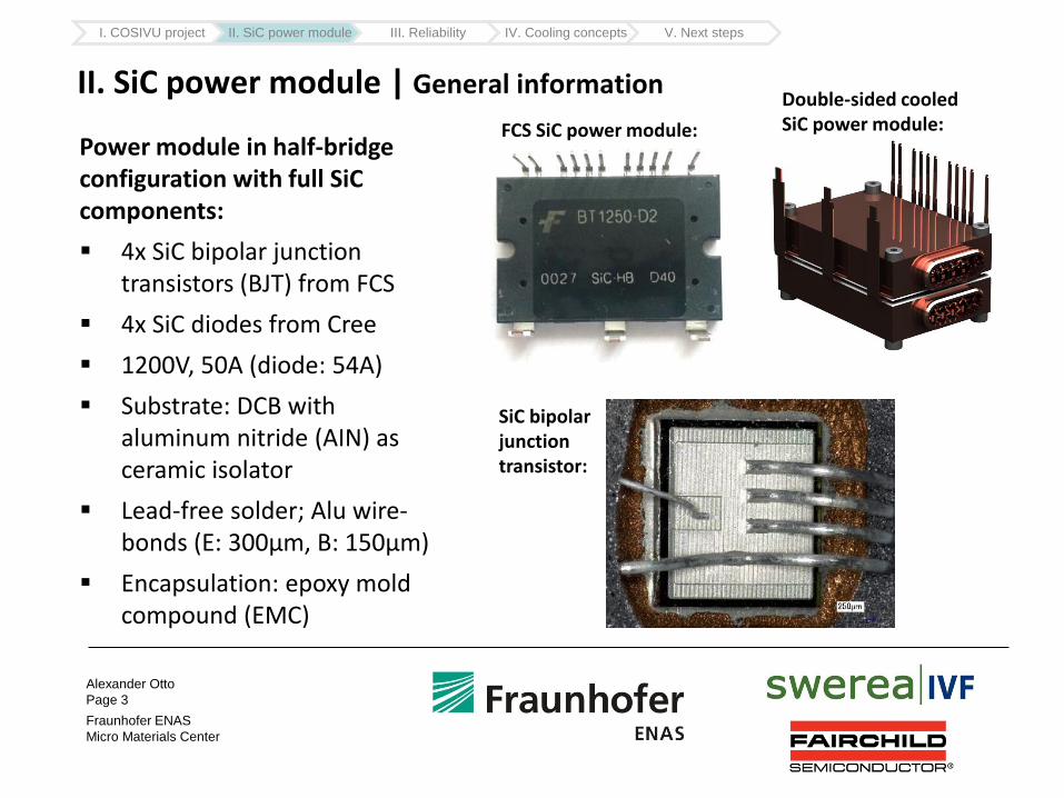
II. SiC power module | General information
Power module in half-bridge configuration with full SiC components:
4x SiC bipolar junction transistors (BJT) from FCS
4x SiC diodes from Cree
1200V, 50A (diode: 54A)
Substrate: DCB with aluminum nitride (AIN) as ceramic isolator
Lead-free solder; Alu wire-bonds (E: 300µm, B: 150µm)
Encapsulation: epoxy mold compound (EMC)
FCS SiC power module:
Double-sided cooled SiC power module:
SiC bipolar junction transistor:
I. COSIVU project II. SiC power module III. Reliability IV. Cooling concepts V. Next steps
Alexander Otto
Page 4
Fraunhofer ENAS
Micro Materials Center
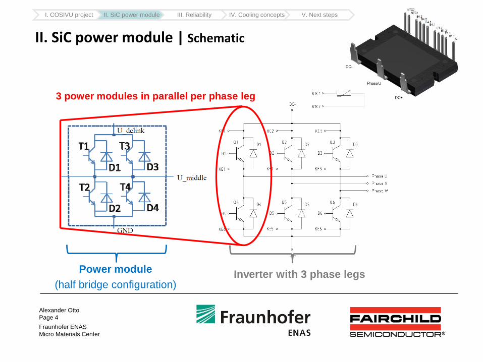
II. SiC power module | Schematic
Power module
(half bridge configuration)
3 power modules in parallel per phase leg
Inverter with 3 phase legs
I. COSIVU project II. SiC power module III. Reliability IV. Cooling concepts V. Next steps
Alexander Otto
Page 5
Fraunhofer ENAS
Micro Materials Center
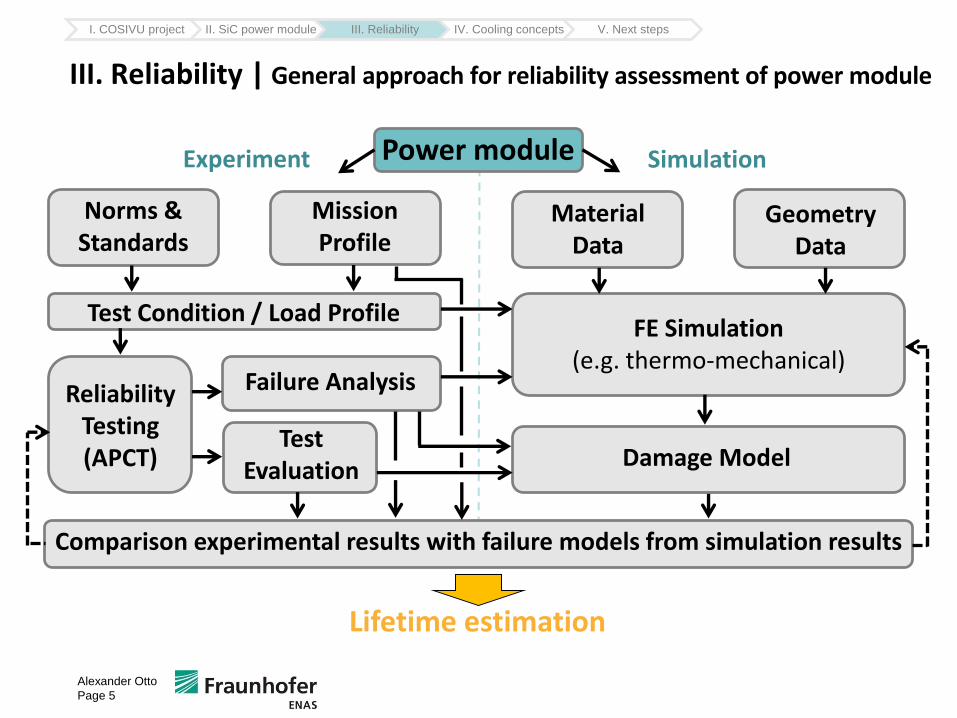
III. Reliability | General approach for reliability assessment of power module
I. COSIVU project II. SiC power module III. Reliability IV. Cooling concepts V. Next steps
Alexander Otto
Page 5
Mission Profile
Lifetime estimation
Test Condition / Load Profile
Norms & Standards
FE Simulation(e.g. thermo-mechanical)
Material Data
Reliability Testing (APCT)
Comparison experimental results with failure models from simulation results
Failure Analysis
Test Evaluation Damage Model
Experiment SimulationPower module
Geometry Data
Alexander Otto
Page 6
Fraunhofer ENAS
Micro Materials Center
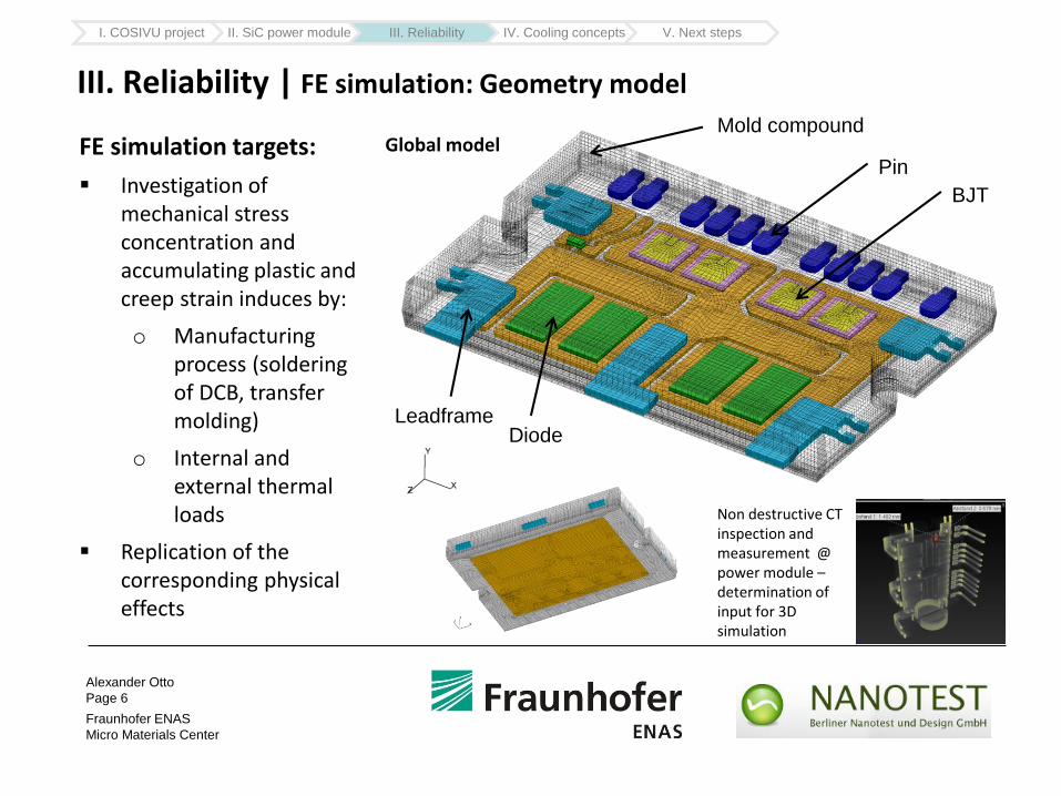
III. Reliability | FE simulation: Geometry model
FE simulation targets:
Investigation of mechanical stress concentration and accumulating plastic and creep strain induces by:
o Manufacturing process (soldering of DCB, transfer molding)
o Internal and external thermal loads
Replication of the corresponding physical effects
Simulation model: Ralf Döring
I. COSIVU project II. SiC power module III. Reliability IV. Cooling concepts V. Next steps
Diode
BJT
Pin
Mold compound
Leadframe
Non destructive CT inspection and measurement @ power module –determination of input for 3D simulation
Global model
Alexander Otto
Page 7
Fraunhofer ENAS
Micro Materials Center
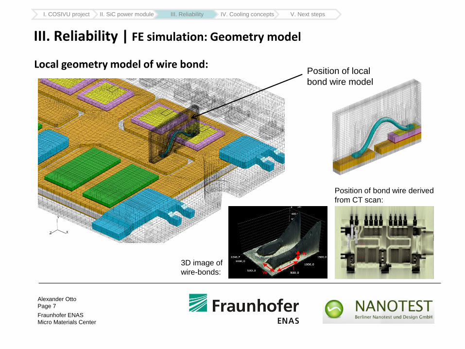
III. Reliability | FE simulation: Geometry model
I. COSIVU project II. SiC power module III. Reliability IV. Cooling concepts V. Next steps
Position of local
bond wire model
Position of bond wire derived
from CT scan:
3D image of
wire-bonds:
Local geometry model of wire bond:
Alexander Otto
Page 8
Fraunhofer ENAS
Micro Materials Center
III. Reliability | FE simulation: Geometry model
I. COSIVU project II. SiC power module III. Reliability IV. Cooling concepts V. Next steps
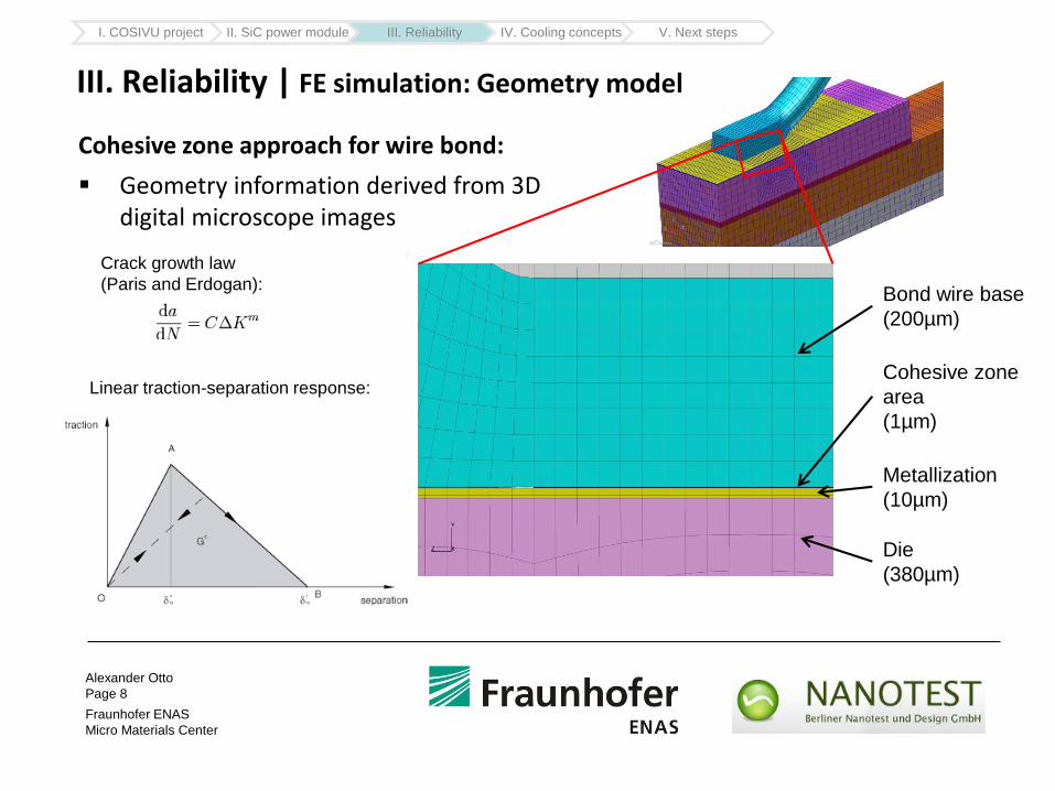
Cohesive zone approach for wire bond:
Geometry information derived from 3D digital microscope images
Bond wire base
(200µm)
Cohesive zone
area
(1µm)
Metallization
(10µm)
Die
(380µm)
Linear traction-separation response:
Crack growth law
(Paris and Erdogan):
Alexander Otto
Page 9
Fraunhofer ENAS
Micro Materials Center
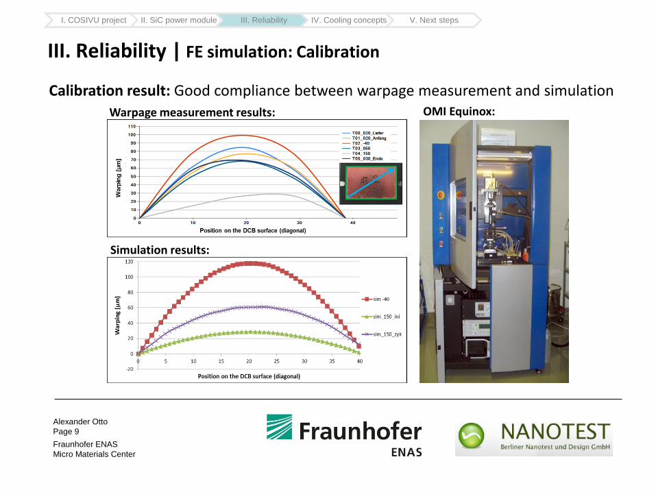
III. Reliability | FE simulation: Calibration
Calibration result: Good compliance between warpage measurement and simulation
Warpage measurement results:
Simulation results:
OMI Equinox:
I. COSIVU project II. SiC power module III. Reliability IV. Cooling concepts V. Next steps
Alexander Otto
Page 10
Fraunhofer ENAS
Micro Materials Center
III. Reliability | FE simulation: First simulation results
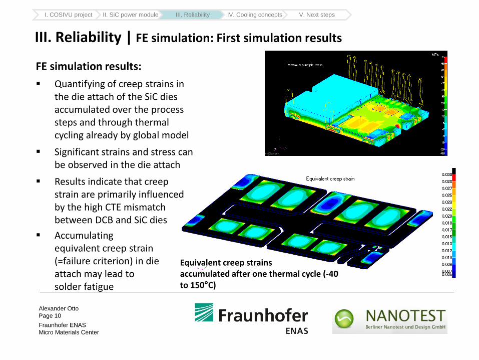
FE simulation results:
Quantifying of creep strains in the die attach of the SiC dies accumulated over the process steps and through thermal cycling already by global model
Significant strains and stress can be observed in the die attach
Results indicate that creep strain are primarily influenced by the high CTE mismatch between DCB and SiC dies
Simulation: Eberhard Kaulfersch
Accumulating equivalent creep strain (=failure criterion) in die attach may lead to solder fatigue
Equivalent creep strains accumulated after one thermal cycle (-40 to 150°C)
I. COSIVU project II. SiC power module III. Reliability IV. Cooling concepts V. Next steps
Alexander Otto
Page 11
Fraunhofer ENAS
Micro Materials Center
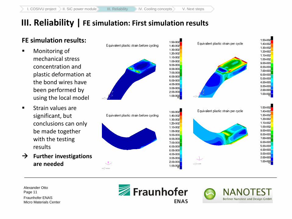
III. Reliability | FE simulation: First simulation results
FE simulation results:
Monitoring of mechanical stress concentration and plastic deformation at the bond wires have been performed by using the local model
Strain values are significant, but conclusions can only be made together with the testing results
Simulation: Eberhard Kaulfersch
I. COSIVU project II. SiC power module III. Reliability IV. Cooling concepts V. Next steps
Further investigations are needed
Alexander Otto
Page 12
Fraunhofer ENAS
Micro Materials Center
Micro Mater ials Center
Prof. B. Michel, Prof. S. Rzepka
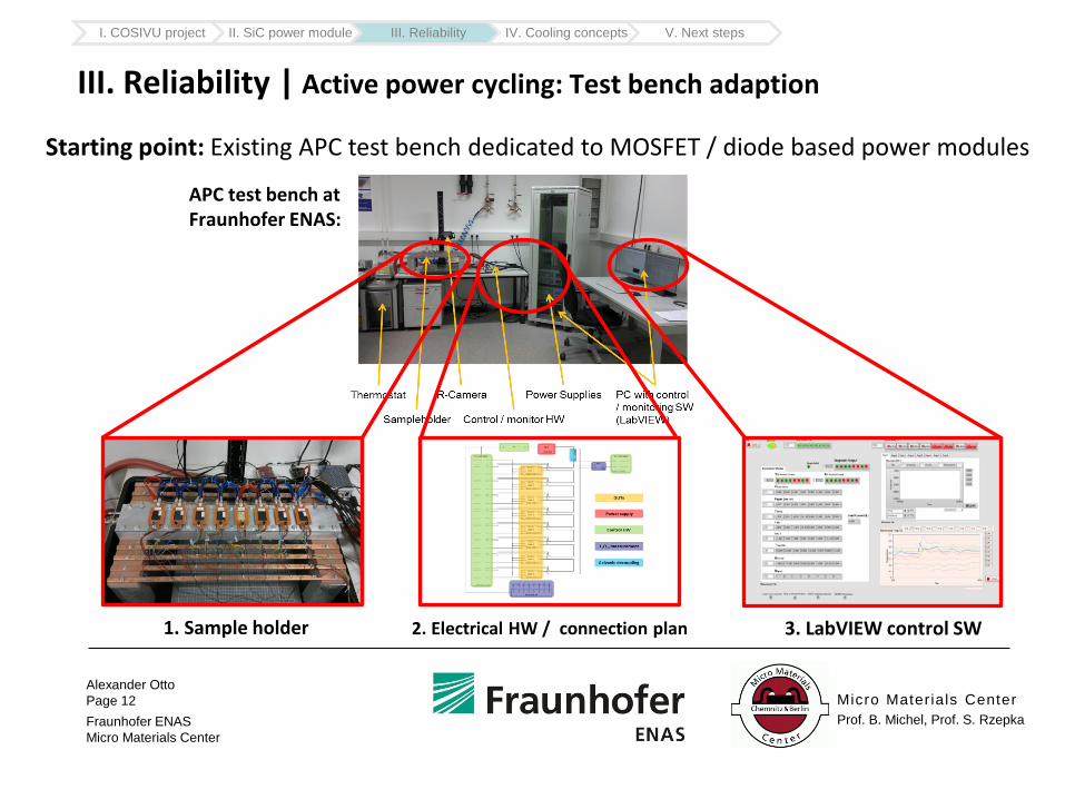
III. Reliability | Active power cycling: Test bench adaption
Starting point: Existing APC test bench dedicated to MOSFET / diode based power modules
APC test bench at Fraunhofer ENAS:
1. Sample holder 3. LabVIEW control SW2. Electrical HW / connection plan
I. COSIVU project II. SiC power module III. Reliability IV. Cooling concepts V. Next steps
Alexander Otto
Page 13
Fraunhofer ENAS
Micro Materials Center
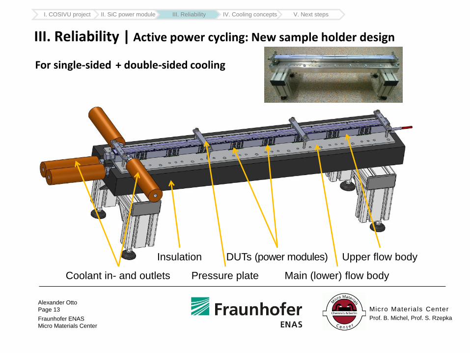
For single-sided
Micro Mater ials Center
Prof. B. Michel, Prof. S. Rzepka
III. Reliability | Active power cycling: New sample holder design
+ double-sided cooling
Coolant in- and outlets
DUTs (power modules)
Pressure plate
Upper flow bodyInsulation
Main (lower) flow body
I. COSIVU project II. SiC power module III. Reliability IV. Cooling concepts V. Next steps
Alexander Otto
Page 14
Fraunhofer ENAS
Micro Materials Center
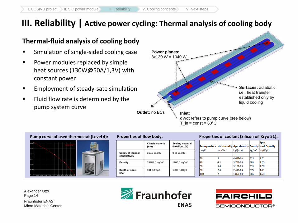
Inlet:
dV/dt refers to pump curve (see below)
T_in = const = 60°C
Outlet: no BCs
Surfaces: adiabatic,
i.e., heat transfer
established only by
liquid cooling
Power planes:
8x130 W = 1040 W
Thermal-fluid analysis of cooling body
Simulation of single-sided cooling case
Power modules replaced by simple heat sources (130W@50A/1,3V) with constant power
Employment of steady-sate simulation
Fluid flow rate is determined by the pump system curve
III. Reliability | Active power cycling: Thermal analysis of cooling body
Pump curve of used thermostat (Level 4): Properties of coolant (Silicon oil Kryo 51):
Chasis material
(Alu)
Sealing material
(Noaflon 100)
Coeef. of thermal
conductivity
313,0 W/mK 0,25 W/mK
Density 19281,0 Kg/m3 1700,0 Kg/m3
Doeff. of spec.
heat
131 KJ/KgK 1300 KJ/KgK
Properties of flow body:
I. COSIVU project II. SiC power module III. Reliability IV. Cooling concepts V. Next steps
Alexander Otto
Page 15
Fraunhofer ENAS
Micro Materials Center
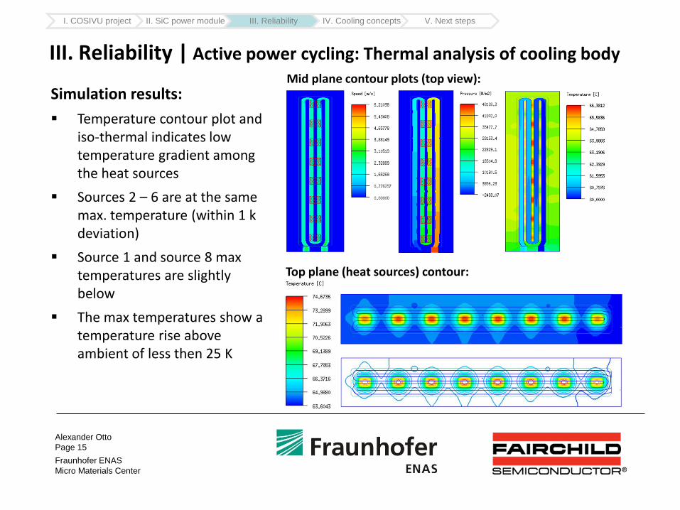
Simulation results:
Temperature contour plot and iso-thermal indicates low temperature gradient among the heat sources
Sources 2 – 6 are at the same max. temperature (within 1 k deviation)
Source 1 and source 8 max temperatures are slightly below
The max temperatures show a temperature rise above ambient of less then 25 K
III. Reliability | Active power cycling: Thermal analysis of cooling bodyMid plane contour plots (top view):
Top plane (heat sources) contour:
I. COSIVU project II. SiC power module III. Reliability IV. Cooling concepts V. Next steps
Alexander Otto
Page 16
Fraunhofer ENAS
Micro Materials Center
Micro Mater ials Center
Prof. B. Michel, Prof. S. Rzepka
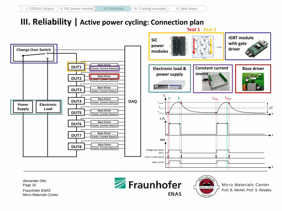
III. Reliability | Active power cycling: Connection plan
I. COSIVU project II. SiC power module III. Reliability IV. Cooling concepts V. Next steps
Change Over Switch
DUT1
DUT2
DUT3
DUT4
DUT5
DUT6
DUT7
DUT8
Electronic
Load
Power
Supply
Base Driver
Const. Current Source
Base Driver
Const. Current Source
Base Driver
Const. Current Source
Base Driver
Const. Current Source
Base Driver
Const. Current Source
Base Driver
Const. Current Source
Base Driver
Const. Current Source
Base Driver
Const. Current Source
DAQ
SiC power modules
Electronic load & power supply
IGBT module with gate driver
Constant current source
Base driver
Test 1 Test 2
Alexander Otto
Page 17
Fraunhofer ENAS
Micro Materials Center
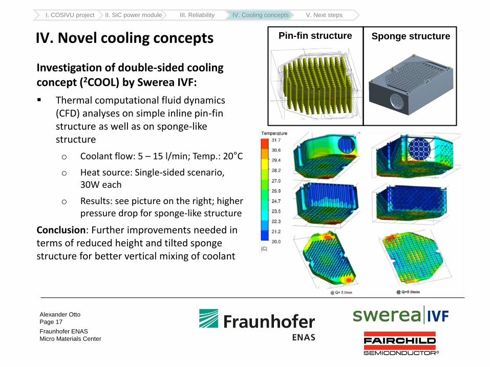
IV. Novel cooling concepts
Investigation of double-sided cooling concept (2COOL) by Swerea IVF:
Thermal computational fluid dynamics (CFD) analyses on simple inline pin-fin structure as well as on sponge-like structure
o Coolant flow: 5 – 15 l/min; Temp.: 20°C
o Heat source: Single-sided scenario, 30W each
o Results: see picture on the right; higher pressure drop for sponge-like structure
Conclusion: Further improvements needed in terms of reduced height and tilted sponge structure for better vertical mixing of coolant
Pin-fin structure Sponge structure
I. COSIVU project II. SiC power module III. Reliability IV. Cooling concepts V. Next steps
Alexander Otto
Page 18
Fraunhofer ENAS
Micro Materials Center
Micro Mater ials Center
Prof. B. Michel, Prof. S. Rzepka
V. Next steps in COSIVU (reliability work for SiC power module)
FE simulation:
Simulation of active power cycles for single-sided power module
Likewise, FE simulation for double-sided cooled power module
Simulation at system level (inverter building block) with detailed sub-models of critical components (power module, current sensor, …)
Active power Cycling:
Test bench adaptation:
o Sample holder: Thermal fluid analysis on double-sided cooling system
o Connection plan / HW: i) Finalization ii) Fully galvanic decoupled constant current sources iii) Base driver
o Adaption of LabVIEW control software
Power cycling tests and failure analysis on single-sided and double-sided cooled power modules
I. COSIVU project II. SiC power module III. Reliability IV. Cooling concepts V. Next steps
Alexander Otto
Page 19
Fraunhofer ENAS
Micro Materials Center
Thank You for Your attention!
Micro Mater ials Center
Prof. B. Michel, Prof. S. Rzepka