Embed Size (px)
Citation preview
1E2B
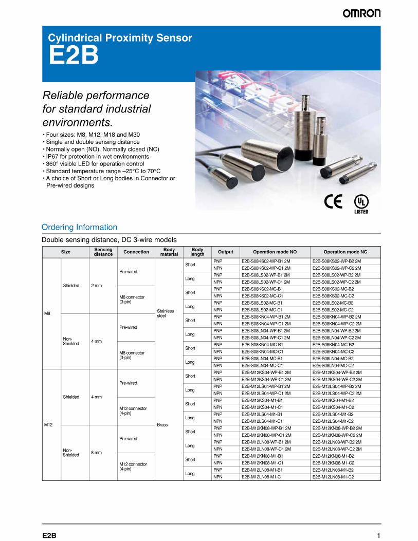
Cylindrical Proximity Sensor
E2BReliable performance for standard industrial environments.• Four sizes: M8, M12, M18 and M30• Single and double sensing distance• Normally open (NO), Normally closed (NC) • IP67 for protection in wet environments• 360° visible LED for operation control• Standard temperature range –25°C to 70°C• A choice of Short or Long bodies in Connector or Pre-wired designs
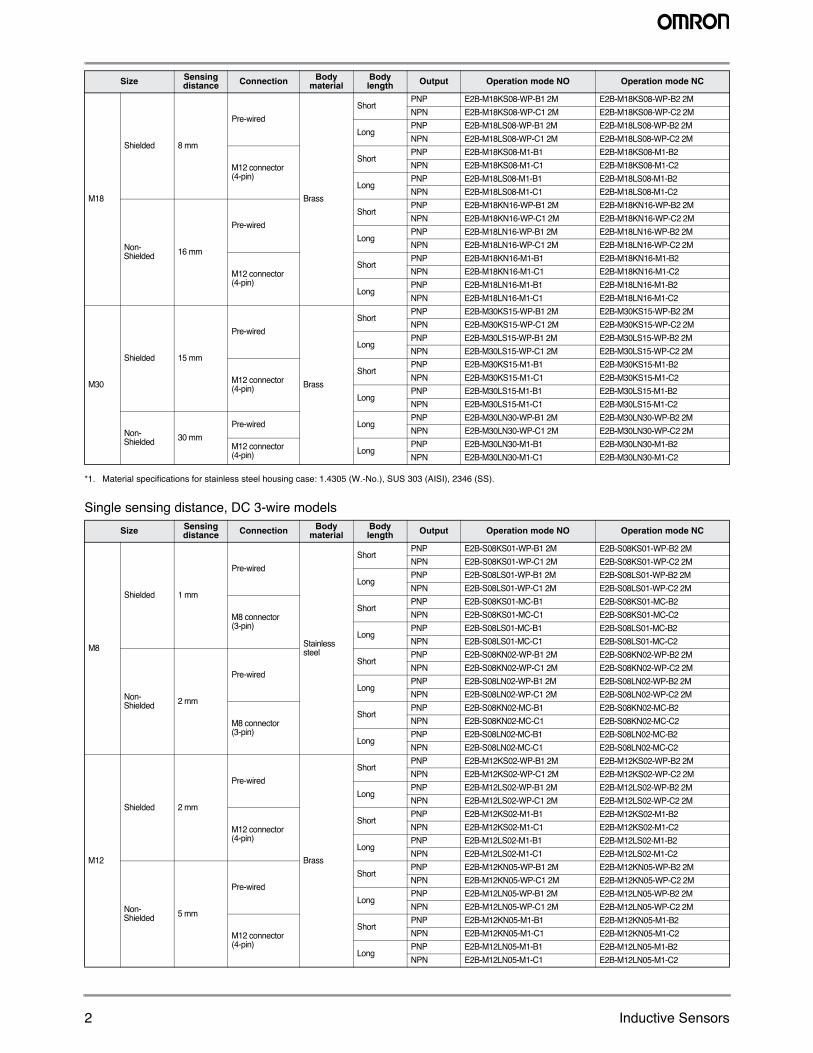
Ordering Information Double sensing distance, DC 3-wire models
Size Sensing distance Connection Body
materialBody length Output Operation mode NO Operation mode NC
M8
Shielded 2 mm
Pre-wired
Stainless steel
ShortPNP E2B-S08KS02-WP-B1 2M
NPN E2B-S08KS02-WP-C1 2M
LongPNP E2B-S08LS02-WP-B1 2M
NPN E2B-S08LS02-WP-C1 2M
M8 connector (3-pin)
ShortPNP E2B-S08KS02-MC-B1
NPN E2B-S08KS02-MC-C1
LongPNP E2B-S08LS02-MC-B1
NPN E2B-S08LS02-MC-C1
Non-Shielded 4 mm
Pre-wired
ShortPNP E2B-S08KN04-WP-B1 2M
NPN E2B-S08KN04-WP-C1 2M
LongPNP E2B-S08LN04-WP-B1 2M
NPN E2B-S08LN04-WP-C1 2M
M8 connector (3-pin)
ShortPNP E2B-S08KN04-MC-B1
NPN E2B-S08KN04-MC-C1
LongPNP E2B-S08LN04-MC-B1
NPN E2B-S08LN04-MC-C1
M12
Shielded 4 mm
Pre-wired
Brass
ShortPNP E2B-M12KS04-WP-B1 2M
NPN E2B-M12KS04-WP-C1 2M
LongPNP E2B-M12LS04-WP-B1 2M
NPN E2B-M12LS04-WP-C1 2M
M12 connector (4-pin)
ShortPNP E2B-M12KS04-M1-B1
NPN E2B-M12KS04-M1-C1
LongPNP E2B-M12LS04-M1-B1
NPN E2B-M12LS04-M1-C1
Non-Shielded 8 mm
Pre-wired
ShortPNP E2B-M12KN08-WP-B1 2M
NPN E2B-M12KN08-WP-C1 2M
LongPNP E2B-M12LN08-WP-B1 2M
NPN E2B-M12LN08-WP-C1 2M
M12 connector (4-pin)
ShortPNP E2B-M12KN08-M1-B1
NPN E2B-M12KN08-M1-C1
LongPNP E2B-M12LN08-M1-B1
NPN E2B-M12LN08-M1-C1
E2B-S08KS02-WP-B2 2M
E2B-S08KS02-WP-C2 2M
E2B-S08LS02-WP-B2 2M
E2B-S08LS02-WP-C2 2M
E2B-S08KS02-MC-B2
E2B-S08KS02-MC-C2
E2B-S08LS02-MC-B2
E2B-S08LS02-MC-C2
E2B-S08KN04-WP-B2 2M
E2B-S08KN04-WP-C2 2M
E2B-S08LN04-WP-B2 2M
E2B-S08LN04-WP-C2 2M
E2B-S08KN04-MC-B2
E2B-S08KN04-MC-C2
E2B-S08LN04-MC-B2
E2B-S08LN04-MC-C2
E2B-M12KS04-WP-B2 2M
E2B-M12KS04-WP-C2 2M
E2B-M12LS04-WP-B2 2M
E2B-M12LS04-WP-C2 2M
E2B-M12KS04-M1-B2
E2B-M12KS04-M1-C2
E2B-M12LS04-M1-B2
E2B-M12LS04-M1-C2
E2B-M12KN08-WP-B2 2M
E2B-M12KN08-WP-C2 2M
E2B-M12LN08-WP-B2 2M
E2B-M12LN08-WP-C2 2M
E2B-M12KN08-M1-B2
E2B-M12KN08-M1-C2
E2B-M12LN08-M1-B2
E2B-M12LN08-M1-C2
2 Inductive Sensors
*1. Material specifications for stainless steel housing case: 1.4305 (W.-No.), SUS 303 (AISI), 2346 (SS).
Single sensing distance, DC 3-wire models
M18
Shielded 8 mm
Pre-wired
Brass
ShortPNP E2B-M18KS08-WP-B1 2M NPN E2B-M18KS08-WP-C1 2M
LongPNP E2B-M18LS08-WP-B1 2M NPN E2B-M18LS08-WP-C1 2M
M12 connector (4-pin)
ShortPNP E2B-M18KS08-M1-B1 NPN E2B-M18KS08-M1-C1
LongPNP E2B-M18LS08-M1-B1 NPN E2B-M18LS08-M1-C1
Non-Shielded 16 mm
Pre-wiredShort
PNP E2B-M18KN16-WP-B1 2M NPN E2B-M18KN16-WP-C1 2M
LongPNP E2B-M18LN16-WP-B1 2M NPN E2B-M18LN16-WP-C1 2M
M12 connector (4-pin)
ShortPNP E2B-M18KN16-M1-B1 NPN E2B-M18KN16-M1-C1
LongPNP E2B-M18LN16-M1-B1 NPN E2B-M18LN16-M1-C1
M30
Shielded 15 mm
Pre-wired
Brass
ShortPNP E2B-M30KS15-WP-B1 2M NPN E2B-M30KS15-WP-C1 2M
LongPNP E2B-M30LS15-WP-B1 2M NPN E2B-M30LS15-WP-C1 2M
M12 connector (4-pin)
ShortPNP E2B-M30KS15-M1-B1 NPN E2B-M30KS15-M1-C1
LongPNP E2B-M30LS15-M1-B1 NPN E2B-M30LS15-M1-C1
Non-Shielded 30 mm
gnoLderiw-erPPNP E2B-M30LN30-WP-B1 2M NPN E2B-M30LN30-WP-C1 2M
M12 connector (4-pin) Long
PNP E2B-M30LN30-M1-B1 NPN E2B-M30LN30-M1-C1
Size Sensing distance Connection Body
materialBody length Output Operation mode NO Operation mode NC
Size Sensing distance Connection Body
materialBody length Output Operation mode NO Operation mode NC
M8
Shielded 1 mm
Pre-wired
Stainless steel
ShortPNP E2B-S08KS01-WP-B1 2MNPN E2B-S08KS01-WP-C1 2M
LongPNP E2B-S08LS01-WP-B1 2MNPN E2B-S08LS01-WP-C1 2M
M8 connector (3-pin)
ShortPNP E2B-S08KS01-MC-B1 NPN E2B-S08KS01-MC-C1
LongPNP E2B-S08LS01-MC-B1 NPN E2B-S08LS01-MC-C1
Non-Shielded 2 mm
Pre-wiredShort
PNP E2B-S08KN02-WP-B1 2MNPN E2B-S08KN02-WP-C1 2M
LongPNP E2B-S08LN02-WP-B1 2MNPN E2B-S08LN02-WP-C1 2M
M8 connector (3-pin)
ShortPNP E2B-S08KN02-MC-B1NPN E2B-S08KN02-MC-C1
LongPNP E2B-S08LN02-MC-B1 NPN E2B-S08LN02-MC-C1
M12
Shielded 2 mm
Pre-wired
Brass
ShortPNP E2B-M12KS02-WP-B1 2M NPN E2B-M12KS02-WP-C1 2M
LongPNP E2B-M12LS02-WP-B1 2MNPN E2B-M12LS02-WP-C1 2M
M12 connector (4-pin)
ShortPNP E2B-M12KS02-M1-B1 NPN E2B-M12KS02-M1-C1
LongPNP E2B-M12LS02-M1-B1 NPN E2B-M12LS02-M1-C1
Non-Shielded 5 mm
Pre-wiredShort
PNP E2B-M12KN05-WP-B1 2M NPN E2B-M12KN05-WP-C1 2M
LongPNP E2B-M12LN05-WP-B1 2M NPN E2B-M12LN05-WP-C1 2M
M12 connector (4-pin)
ShortPNP E2B-M12KN05-M1-B1NPN E2B-M12KN05-M1-C1
LongPNP E2B-M12LN05-M1-B1 NPN E2B-M12LN05-M1-C1
E2B-M18KS08-WP-B2 2ME2B-M18KS08-WP-C2 2M E2B-M18LS08-WP-B2 2ME2B-M18LS08-WP-C2 2ME2B-M18KS08-M1-B2E2B-M18KS08-M1-C2E2B-M18LS08-M1-B2E2B-M18LS08-M1-C2E2B-M18KN16-WP-B2 2ME2B-M18KN16-WP-C2 2ME2B-M18LN16-WP-B2 2M E2B-M18LN16-WP-C2 2M E2B-M18KN16-M1-B2E2B-M18KN16-M1-C2E2B-M18LN16-M1-B2E2B-M18LN16-M1-C2E2B-M30KS15-WP-B2 2M E2B-M30KS15-WP-C2 2ME2B-M30LS15-WP-B2 2M E2B-M30LS15-WP-C2 2ME2B-M30KS15-M1-B2E2B-M30KS15-M1-C2E2B-M30LS15-M1-B2E2B-M30LS15-M1-C2 E2B-M30LN30-WP-B2 2M E2B-M30LN30-WP-C2 2ME2B-M30LN30-M1-B2E2B-M30LN30-M1-C2
E2B-S08KS01-WP-B2 2ME2B-S08KS01-WP-C2 2ME2B-S08LS01-WP-B2 2ME2B-S08LS01-WP-C2 2M E2B-S08KS01-MC-B2E2B-S08KS01-MC-C2E2B-S08LS01-MC-B2E2B-S08LS01-MC-C2E2B-S08KN02-WP-B2 2M E2B-S08KN02-WP-C2 2ME2B-S08LN02-WP-B2 2ME2B-S08LN02-WP-C2 2ME2B-S08KN02-MC-B2E2B-S08KN02-MC-C2E2B-S08LN02-MC-B2E2B-S08LN02-MC-C2E2B-M12KS02-WP-B2 2ME2B-M12KS02-WP-C2 2ME2B-M12LS02-WP-B2 2ME2B-M12LS02-WP-C2 2ME2B-M12KS02-M1-B2E2B-M12KS02-M1-C2E2B-M12LS02-M1-B2E2B-M12LS02-M1-C2E2B-M12KN05-WP-B2 2ME2B-M12KN05-WP-C2 2ME2B-M12LN05-WP-B2 2ME2B-M12LN05-WP-C2 2ME2B-M12KN05-M1-B2E2B-M12KN05-M1-C2E2B-M12LN05-M1-B2E2B-M12LN05-M1-C2
3E2B
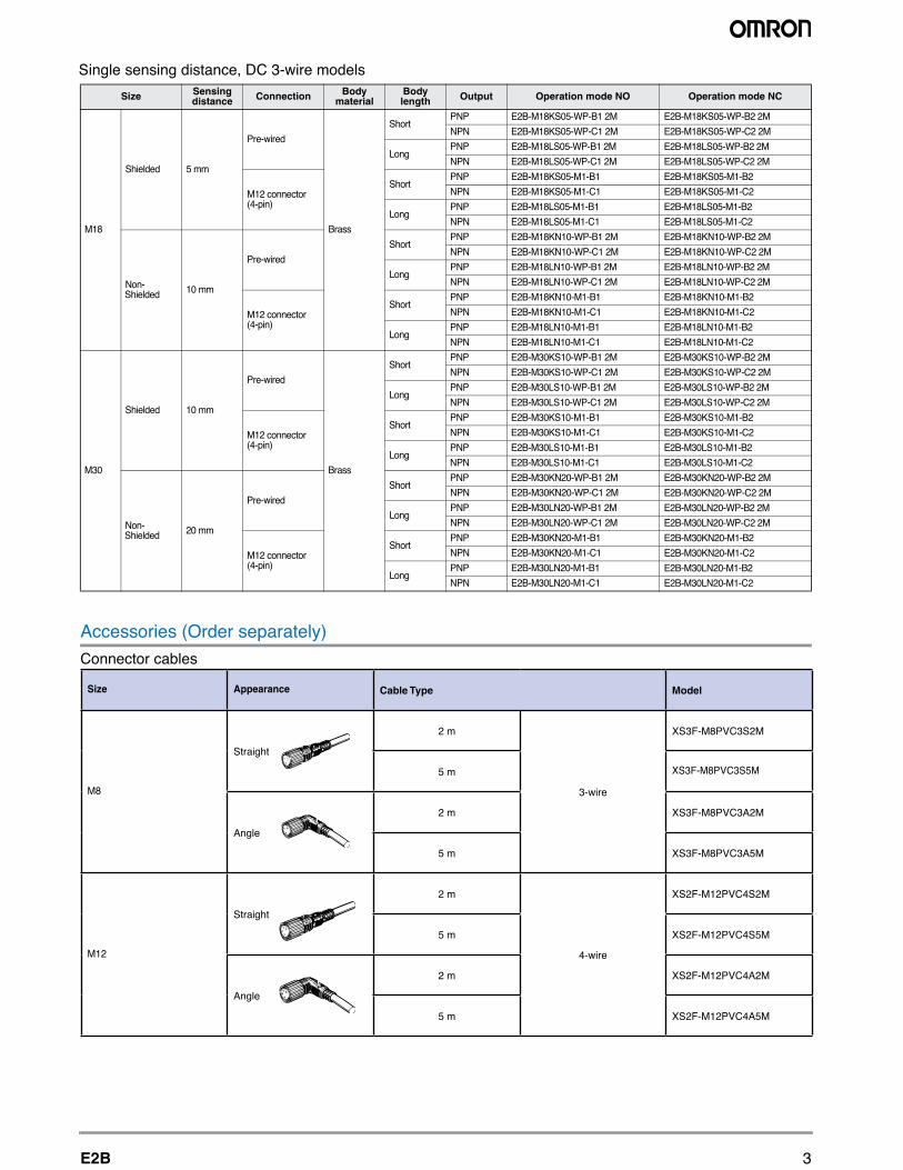
Accessories (Order separately)Connector cables
M18
Shielded 5 mm
Pre-wired
Brass
ShortPNP E2B-M18KS05-WP-B1 2M
NPN E2B-M18KS05-WP-C1 2M
LongPNP E2B-M18LS05-WP-B1 2M
NPN E2B-M18LS05-WP-C1 2M
M12 connector (4-pin)
ShortPNP E2B-M18KS05-M1-B1
NPN E2B-M18KS05-M1-C1
LongPNP E2B-M18LS05-M1-B1
NPN E2B-M18LS05-M1-C1
Non-Shielded 10 mm
Pre-wired
ShortPNP E2B-M18KN10-WP-B1 2M
NPN E2B-M18KN10-WP-C1 2M
LongPNP E2B-M18LN10-WP-B1 2M
NPN E2B-M18LN10-WP-C1 2M
M12 connector (4-pin)
ShortPNP E2B-M18KN10-M1-B1
NPN E2B-M18KN10-M1-C1
LongPNP E2B-M18LN10-M1-B1
NPN E2B-M18LN10-M1-C1
M30
Shielded 10 mm
Pre-wired
Brass
ShortPNP E2B-M30KS10-WP-B1 2M
NPN E2B-M30KS10-WP-C1 2M
LongPNP E2B-M30LS10-WP-B1 2M
NPN E2B-M30LS10-WP-C1 2M
M12 connector (4-pin)
ShortPNP E2B-M30KS10-M1-B1
NPN E2B-M30KS10-M1-C1
LongPNP E2B-M30LS10-M1-B1
NPN E2B-M30LS10-M1-C1
Non-Shielded 20 mm
Pre-wired
ShortPNP E2B-M30KN20-WP-B1 2M
NPN E2B-M30KN20-WP-C1 2M
LongPNP E2B-M30LN20-WP-B1 2M
NPN E2B-M30LN20-WP-C1 2M
M12 connector (4-pin)
ShortPNP E2B-M30KN20-M1-B1
NPN E2B-M30KN20-M1-C1
LongPNP E2B-M30LN20-M1-B1
NPN E2B-M30LN20-M1-C1
E2B-M18KS05-WP-B2 2M
E2B-M18KS05-WP-C2 2M
E2B-M18LS05-WP-B2 2M
E2B-M18LS05-WP-C2 2M
E2B-M18KS05-M1-B2
E2B-M18KS05-M1-C2
E2B-M18LS05-M1-B2
E2B-M18LS05-M1-C2
E2B-M18KN10-WP-B2 2M
E2B-M18KN10-WP-C2 2M
E2B-M18LN10-WP-B2 2M
E2B-M18LN10-WP-C2 2M
E2B-M18KN10-M1-B2
E2B-M18KN10-M1-C2
E2B-M18LN10-M1-B2
E2B-M18LN10-M1-C2
E2B-M30KS10-WP-B2 2M
E2B-M30KS10-WP-C2 2M
E2B-M30LS10-WP-B2 2M
E2B-M30LS10-WP-C2 2M
E2B-M30KS10-M1-B2
E2B-M30KS10-M1-C2
E2B-M30LS10-M1-B2
E2B-M30LS10-M1-C2
E2B-M30KN20-WP-B2 2M
E2B-M30KN20-WP-C2 2M
E2B-M30LN20-WP-B2 2M
E2B-M30LN20-WP-C2 2M
E2B-M30KN20-M1-B2
E2B-M30KN20-M1-C2
E2B-M30LN20-M1-B2
E2B-M30LN20-M1-C2
Size Sensing distance Connection Body
materialBody length Output Operation mode NO Operation mode NC
Single sensing distance, DC 3-wire models
Size Appearance Cable Type Model
M8
Straight
2 m
3-wire
XS3F-M8PVC3S2M
5 m XS3F-M8PVC3S5M
Angle
2 m XS3F-M8PVC3A2M
5 m XS3F-M8PVC3A5M
M12
Straight
2 m
4-wire
XS2F-M12PVC4S2M
5 m XS2F-M12PVC4S5M
Angle
2 m XS2F-M12PVC4A2M
5 m XS2F-M12PVC4A5M
4 Inductive Sensors
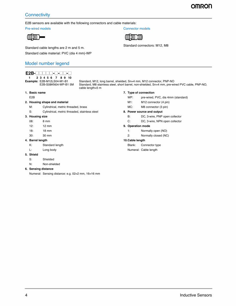
ConnectivityE2B sensors are available with the following connectors and cable materials:Pre-wired models
Standard cable lengths are 2 m and 5 m. Standard cable material: PVC (dia 4 mm)-WP
Connector models
Standard connectors: M12, M8
Model number legend
Example: E2B-M12LS04-M1-B1 Standard, M12, long barrel, shielded, Sn=4 mm, M12 connector, PNP-NOE2B-S08KN04-WP-B1 5M Standard, M8 stainless steel, short barrel, non-shielded, Sn=4 mm, pre-wired PVC cable, PNP-NO,
cable length=5 m1. Basic name
E2B2. Housing shape and material
M: Cylindrical, metric threaded, brassS: Cylindrical, metric threaded, stainless steel
3. Housing size08: 8 mm12: 12 mm18: 18 mm30: 30 mm
4. Barrel lengthK: Standard lengthL: Long body
5. ShieldS: ShieldedN: Non-shielded
6. Sensing distanceNumeral: Sensing distance: e.g. 02=2 mm, 16=16 mm
7. Type of connectionWP: pre-wired, PVC, dia 4mm (standard)M1: M12 connector (4 pin)MC: M8 connector (3 pin)
8. Power source and outputB: DC, 3-wire, PNP open collectorC: DC, 3-wire, NPN open collector
9. Operation mode1: Normally open (NO)2: Normally closed (NC)
10.Cable lengthBlank: Connector typeNumeral: Cable length
2 3 4 5 6 7 8 9 101E2B- - - -
5E2B
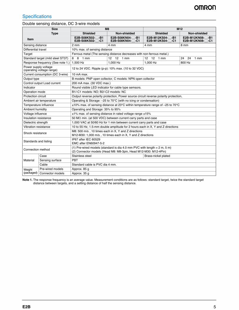
SpecificationsDouble sensing distance, DC 3-wire models
Note 1. The response frequency is an average value. Measurement conditions are as follows: standard target, twice the standard target distance between targets, and a setting distance of half the sensing distance.
Size M8 M12Type Shielded Non-shielded Shielded Non-shielded
Item E2B-S08KS02-__-B1 E2B-S08KS02-__-C1
E2B-S08KN04-__-B1 E2B-S08KN04-__-C1
E2B-M12KS04-__-B1 E2B-M12KS04-__-C1
E2B-M12KN08-__-B1 E2B-M12KN08-__-C1
Sensing distance 2 mm 4 mm 4 mm 8 mmDifferential travel 10% max. of sensing distance
cnatsid gnisnes ehT( latem suorreFtegraT e decreases with non-ferrous metal.)Standard target (mild steel ST37) 8 × 8 × 1 mm 12 × 12 × 1 mm 12 × 12 × 1 mm 24 × 24 × 1 mmResponse frequency (See note 1.) 1,500 Hz 1,000 Hz 1,000 Hz 800 HzPower supply voltage (operating voltage range) 12 to 24 VDC. Ripple (p-p): 10% max. (10 to 32 VDC)
Current consumption (DC 3-wire) 10 mA max.rotcelloc nepo NPN :sledom C ,rotcelloc nepo PNP :sledom Bepyt tuptuO
Control output Load current 200 mA max. (30 VDC max.) idni DEL elbisiv dnuoRrotacidnI cator for cable type semsors.
Operation mode B1/-C1 models: NO; B2/-C2 models: NCProtection circuit Output reverse polarity protection, Power source circuit reverse polarity protection,Ambient air temperature Operating & Storage: –25 to 70°C (with no icing or condensation) Temperature influence ±10% max. of sensing distance at 23°C within temperature range of –25 to 70°CAmbient humidity Operating and Storage: 35% to 95% Voltage influence ±1% max. of sensing distance in rated voltage range ±15% Insulation resistance 50 MΩ min. (at 500 VDC) between current carry parts and case Dielectric strength 1,000 VAC at 50/60 Hz for 1 min between current carry parts and case Vibration resistance 10 to 55 Hz, 1.5-mm double amplitude for 2 hours each in X, Y and Z directions
Shock resistanceM8: 500 m/s², 10 times each in X, Y and Z directions M12-M30: 1,000 m/s², 10 times each in X, Y and Z directions
Standards and listingIP67 after IEC 60529EMC after EN60947-5-2
Connection method(1) Pre-wired models (standard is dia 4.0 mm PVC with length = 2 m, 5 m) (2) Connector models (Head M8: M8-3pin, Head M12-M30: M12-4Pin)
MaterialrBleets sselniatSesaC ass-nickel plated
Sensing surface PBTCable Standard cable is PVC dia 4 mm.
Weight (packaged)
Pre-wired models Approx. 85 gConnector models Approx. 35 g
6 Inductive Sensors
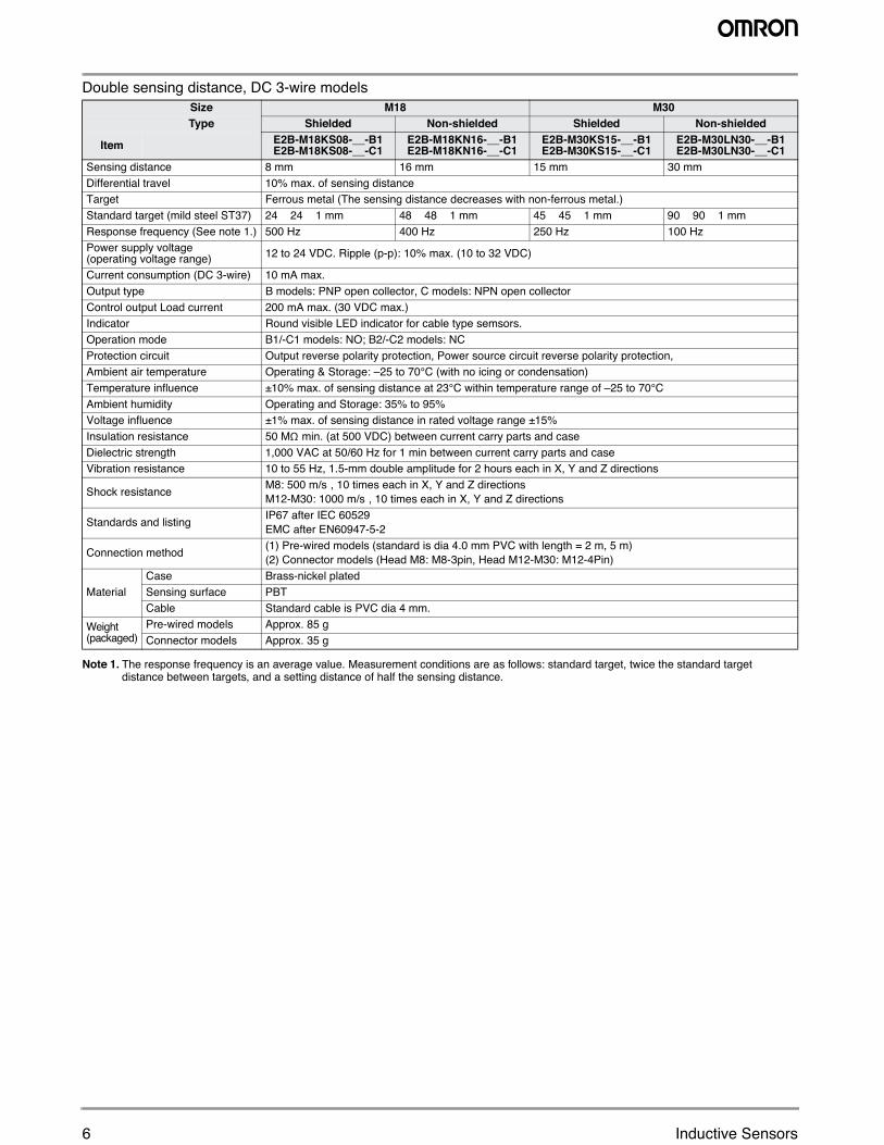
Double sensing distance, DC 3-wire models
Note 1. The response frequency is an average value. Measurement conditions are as follows: standard target, twice the standard target distance between targets, and a setting distance of half the sensing distance.
Size M18 M30Type Shielded Non-shielded Shielded Non-shielded
Item E2B-M18KS08-__-B1 E2B-M18KS08-__-C1
E2B-M18KN16-__-B1 E2B-M18KN16-__-C1
E2B-M30KS15-__-B1 E2B-M30KS15-__-C1
E2B-M30LN30-__-B1 E2B-M30LN30-__-C1
Sensing distance 8 mm 16 mm 15 mm 30 mmDifferential travel 10% max. of sensing distance
ecnatsid gnisnes ehT( latem suorreFtegraT decreases with non-ferrous metal.)Standard target (mild steel ST37) 24 × 24 × 1 mm 48 × 48 × 1 mm 45 × 45 × 1 mm 90 × 90 × 1 mmResponse frequency (See note 1.) 500 Hz 400 Hz 250 Hz 100 HzPower supply voltage (operating voltage range) 12 to 24 VDC. Ripple (p-p): 10% max. (10 to 32 VDC)
Current consumption (DC 3-wire) 10 mA max.rotcelloc nepo NPN :sledom C ,rotcelloc nepo PNP :sledom Bepyt tuptuO
Control output Load current 200 mA max. (30 VDC max.) acidni DEL elbisiv dnuoRrotacidnI tor for cable type semsors.
Operation mode B1/-C1 models: NO; B2/-C2 models: NCProtection circuit Output reverse polarity protection, Power source circuit reverse polarity protection,Ambient air temperature Operating & Storage: –25 to 70°C (with no icing or condensation)Temperature influence ±10% max. of sensing distance at 23°C within temperature range of –25 to 70°CAmbient humidity Operating and Storage: 35% to 95% Voltage influence ±1% max. of sensing distance in rated voltage range ±15% Insulation resistance 50 MΩ min. (at 500 VDC) between current carry parts and case Dielectric strength 1,000 VAC at 50/60 Hz for 1 min between current carry parts and case Vibration resistance 10 to 55 Hz, 1.5-mm double amplitude for 2 hours each in X, Y and Z directions
Shock resistanceM8: 500 m/s², 10 times each in X, Y and Z directionsM12-M30: 1000 m/s², 10 times each in X, Y and Z directions
Standards and listingIP67 after IEC 60529EMC after EN60947-5-2
Connection method(1) Pre-wired models (standard is dia 4.0 mm PVC with length = 2 m, 5 m)(2) Connector models (Head M8: M8-3pin, Head M12-M30: M12-4Pin)
MaterialCase Brass-nickel platedSensing surface PBTCable Standard cable is PVC dia 4 mm.
Weight (packaged)
Pre-wired models Approx. 85 gConnector models Approx. 35 g
7E2B
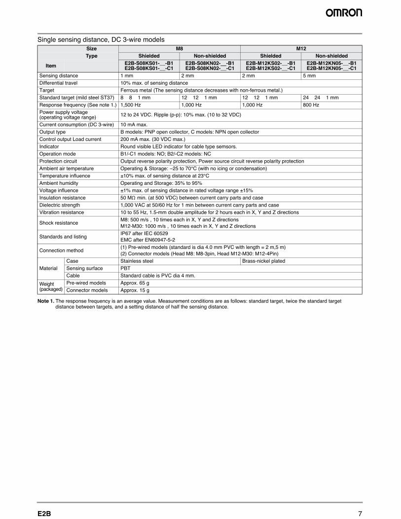
Single sensing distance, DC 3-wire models
Note 1. The response frequency is an average value. Measurement conditions are as follows: standard target, twice the standard target distance between targets, and a setting distance of half the sensing distance.
Size M8 M12Type Shielded Non-shielded Shielded Non-shielded
Item E2B-S08KS01-__-B1E2B-S08KS01-__-C1
E2B-S08KN02-__-B1E2B-S08KN02-__-C1
E2B-M12KS02-__-B1E2B-M12KS02-__-C1
E2B-M12KN05-__-B1E2B-M12KN05-__-C1
Sensing distance 1 mm 2 mm 2 mm 5 mmDifferential travel 10% max. of sensing distance
cnatsid gnisnes ehT( latem suorreFtegraT e decreases with non-ferrous metal.)Standard target (mild steel ST37) 8 × 8 × 1 mm 12 × 12 × 1 mm 12 × 12 × 1 mm 24 × 24 × 1 mmResponse frequency (See note 1.) 1,500 Hz 1,000 Hz 1,000 Hz 800 HzPower supply voltage (operating voltage range) 12 to 24 VDC. Ripple (p-p): 10% max. (10 to 32 VDC)
Current consumption (DC 3-wire) 10 mA max.rotcelloc nepo NPN :sledom C ,rotcelloc nepo PNP :sledom Bepyt tuptuO
Control output Load current 200 mA max. (30 VDC max.) idni DEL elbisiv dnuoRrotacidnI cator for cable type semsors.
Operation mode B1/-C1 models: NO; B2/-C2 models: NCProtection circuit Output reverse polarity protection, Power source circuit reverse polarity protectionAmbient air temperature Operating & Storage: −25 to 70°C (with no icing or condensation)Temperature influence ±10% max. of sensing distance at 23°CAmbient humidity Operating and Storage: 35% to 95%Voltage influence ±1% max. of sensing distance in rated voltage range ±15%Insulation resistance 50 MΩ min. (at 500 VDC) between current carry parts and caseDielectric strength 1,000 VAC at 50/60 Hz for 1 min between current carry parts and caseVibration resistance 10 to 55 Hz, 1.5-mm double amplitude for 2 hours each in X, Y and Z directions
Shock resistanceM8: 500 m/s², 10 times each in X, Y and Z directionsM12-M30: 1000 m/s², 10 times each in X, Y and Z directions
Standards and listingIP67 after IEC 60529EMC after EN60947-5-2
Connection method(1) Pre-wired models (standard is dia 4.0 mm PVC with length = 2 m,5 m)(2) Connector models (Head M8: M8-3pin, Head M12-M30: M12-4Pin)
MaterialrBleets sselniatSesaC ass-nickel plated
Sensing surface PBTCable Standard cable is PVC dia 4 mm.
Weight (packaged)
Pre-wired models Approx. 65 gConnector models Approx. 15 g
8 Inductive Sensors
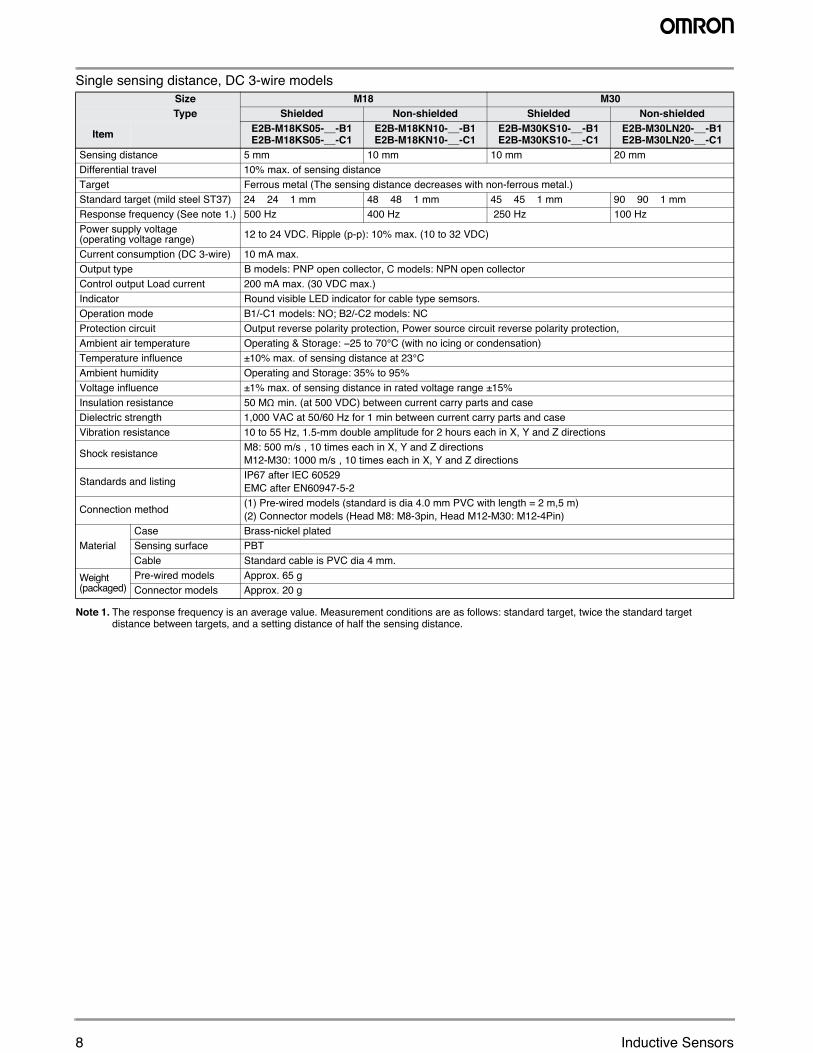
Single sensing distance, DC 3-wire models
Note 1. The response frequency is an average value. Measurement conditions are as follows: standard target, twice the standard target distance between targets, and a setting distance of half the sensing distance.
Size M18 M30Type Shielded Non-shielded Shielded Non-shielded
Item E2B-M18KS05-__-B1E2B-M18KS05-__-C1
E2B-M18KN10-__-B1E2B-M18KN10-__-C1
E2B-M30KS10-__-B1E2B-M30KS10-__-C1
E2B-M30LN20-__-B1E2B-M30LN20-__-C1
Sensing distance 5 mm 10 mm 10 mm 20 mmDifferential travel 10% max. of sensing distance
ecnatsid gnisnes ehT( latem suorreFtegraT decreases with non-ferrous metal.)Standard target (mild steel ST37) 24 × 24 × 1 mm 48 × 48 × 1 mm 45 × 45 × 1 mm 90 × 90 × 1 mmResponse frequency (See note 1.) 500 Hz 400 Hz 250 Hz 100 HzPower supply voltage(operating voltage range) 12 to 24 VDC. Ripple (p-p): 10% max. (10 to 32 VDC)
Current consumption (DC 3-wire) 10 mA max.rotcelloc nepo NPN :sledom C ,rotcelloc nepo PNP :sledom Bepyt tuptuO
Control output Load current 200 mA max. (30 VDC max.) acidni DEL elbisiv dnuoRrotacidnI tor for cable type semsors.
Operation mode B1/-C1 models: NO; B2/-C2 models: NCProtection circuit Output reverse polarity protection, Power source circuit reverse polarity protection,Ambient air temperature Operating & Storage: −25 to 70°C (with no icing or condensation) Temperature influence ±10% max. of sensing distance at 23°C Ambient humidity Operating and Storage: 35% to 95% Voltage influence ±1% max. of sensing distance in rated voltage range ±15% Insulation resistance 50 MΩ min. (at 500 VDC) between current carry parts and case Dielectric strength 1,000 VAC at 50/60 Hz for 1 min between current carry parts and case Vibration resistance 10 to 55 Hz, 1.5-mm double amplitude for 2 hours each in X, Y and Z directions
Shock resistanceM8: 500 m/s², 10 times each in X, Y and Z directionsM12-M30: 1000 m/s², 10 times each in X, Y and Z directions
Standards and listing IP67 after IEC 60529EMC after EN60947-5-2
Connection method(1) Pre-wired models (standard is dia 4.0 mm PVC with length = 2 m,5 m)(2) Connector models (Head M8: M8-3pin, Head M12-M30: M12-4Pin)
MaterialCase Brass-nickel platedSensing surface PBTCable Standard cable is PVC dia 4 mm.
Weight (packaged)
Pre-wired models Approx. 65 gConnector models Approx. 20 g
9E2B
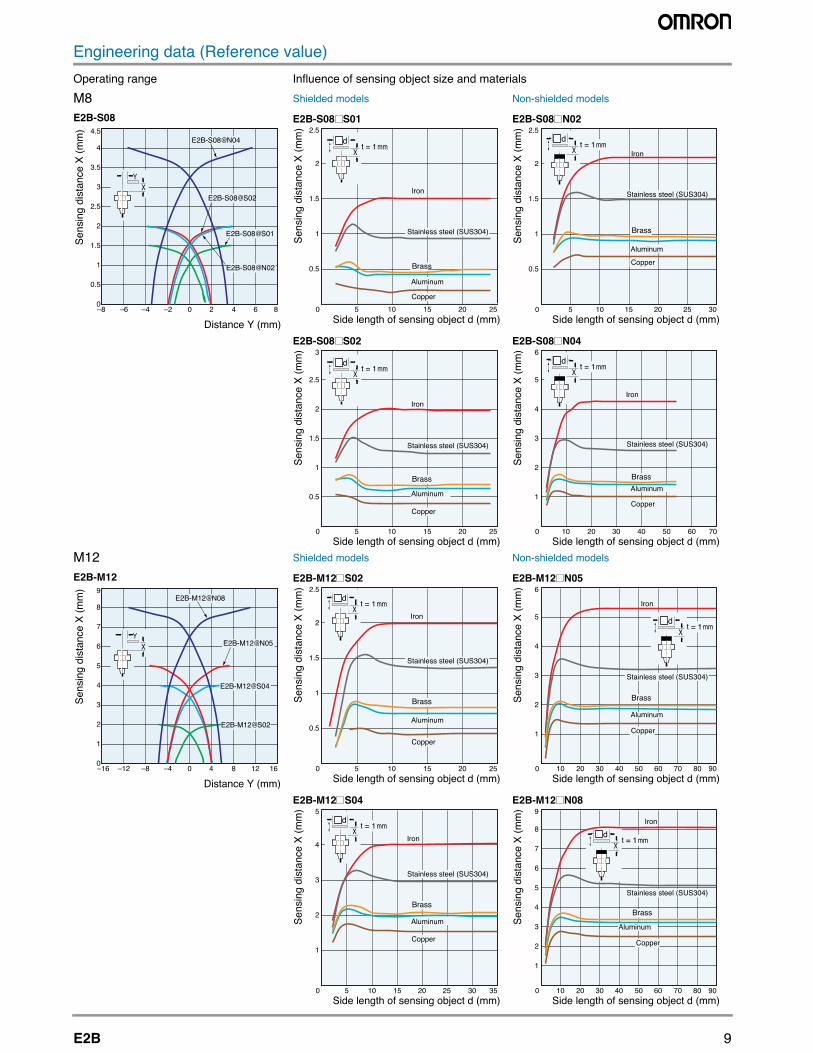
Engineering data (Reference value)slairetam dna ezis tcejbo gnisnes fo ecneulfnIegnar gnitarepO
M8 sledom dedleihs-noNsledom dedleihS
M12 sledom dedleihs-noNsledom dedleihS
Sens
ing
dist
ance
X (m
m)
E2B-S084.5
4
3.5
3
2.5
2
1.5
1
0.5
0
Distance Y (mm)
XY
–8 –6 –4 –2 0 2 4 6 8
E2B-S08@S01
E2B-S08@N02
E2B-S08@N04
E2B-S08@S02
Brass
Copper
Iron
Stainless steel (SUS304)
Aluminum
t = 1 mmX
d
E2B-S08 S01
Sens
ing
dist
ance
X (m
m)
Side length of sensing object d (mm)0 5 10 15 20 25
2.5
2
1.5
1
0.5
Brass
Copper
Iron
Stainless steel (SUS304)
Aluminum
t = 1 mmX
d
E2B-S08 N02
Sens
ing
dist
ance
X (m
m)
Side length of sensing object d (mm)0 5 10 15 20 25 30
2.5
2
1.5
1
0.5
Brass
Copper
Iron
Stainless steel (SUS304)
Aluminum
t = 1 mmX
d
E2B-S08 S02
Sens
ing
dist
ance
X (m
m)
Side length of sensing object d (mm)0 5 10 15 20 25
3
2.5
2
1.5
1
0.5
Brass
Copper
Iron
Stainless steel (SUS304)
Aluminum
t = 1 mmX
d
E2B-S08 N04
Sens
ing
dist
ance
X (m
m)
Side length of sensing object d (mm)0 10 20 30 40 50 60 70
6
5
4
3
2
1
E2B-M12@S04
E2B-M12@S02
E2B-M12@N05
Sens
ing
dist
ance
X (m
m)
E2B-M129
8
7
6
5
4
3
2
1
0
Distance Y (mm)
XY
–16 –12 –8 –4 0 4 8 12 16
E2B-M12@N08
Brass
Copper
Iron
Stainless steel (SUS304)
Aluminum
t = 1 mmX
d
E2B-M12 S02
Sens
ing
dist
ance
X (m
m)
Side length of sensing object d (mm)0 5 10 15 20 25
2.5
2
1.5
1
0.5
Brass
Copper
Iron
Stainless steel (SUS304)
Aluminum
t = 1 mmX
d
E2B-M12 N05
Sens
ing
dist
ance
X (m
m)
Side length of sensing object d (mm)0 10 20 30 40 50 60 70 80 90
6
5
4
3
2
1
Brass
Copper
Iron
Stainless steel (SUS304)
Aluminum
t = 1 mmX
d
E2B-M12 S04
Sens
ing
dist
ance
X (m
m)
Side length of sensing object d (mm)0 5 10 15 20 25 30 35
5
4
3
2
1
Brass
Copper
Iron
Aluminum
t = 1 mmX
d
E2B-M12 N08
Sens
ing
dist
ance
X (m
m)
Side length of sensing object d (mm)0 10 20 30 40 50 60 70 80 90
9
8
7
6
5
4
3
2
1
Stainless steel (SUS304)
10 Inductive Sensors
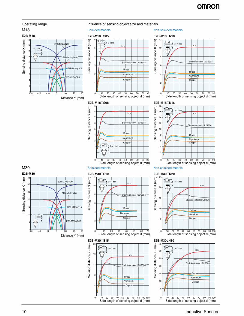
M18 sledom dedleihs-noNsledom dedleihS
M30 sledom dedleihs-noNsledom dedleihS
snes fo ecneulfnIegnar gnitarepO ing object size and materials
Distance Y (mm)
Sens
ing
dist
ance
X (m
m)
E2B-M1818
16
14
12
10
8
6
4
2
0
XY
–30 –20 –10 0 10 20 30
E2B-M18@S05
E2B-M18@S08
E2B-M18@N16
E2B-M18@N10
Brass
Copper
Iron
Stainless steel (SUS304)
Aluminum
t = 1 mmX
d
E2B-M18 S05
Sens
ing
dist
ance
X (m
m)
Side length of sensing object d (mm)
6
5
4
3
2
1
0 10 20 30 40 50 60 70 80 90
Brass
Copper
Iron
Stainless steel (SUS304)
Aluminum
t = 1 mmX
d
E2B-M18 N10
Sens
ing
dist
ance
X (m
m)
Side length of sensing object d (mm)0 10 20 30 40 50 60 70 80 90
12
10
8
6
4
2
Brass
Copper
Iron
Stainless steel (SUS304)
Aluminum
t = 1 mmX
d
E2B-M18 S08
Sens
ing
dist
ance
X (m
m)
Side length of sensing object d (mm)0 10 20 30 40 50 60 70 80 90
9
8
7
6
5
4
3
2
1
Brass
Copper
Iron
Stainless steel (SUS304)
Aluminum
t = 1 mmX
d
E2B-M18 N16
Sens
ing
dist
ance
X (m
m)
Side length of sensing object d (mm)0 10 20 30 40 50 60 70 80 90
18
16
14
12
10
8
6
4
2
Sens
ing
dist
ance
X (m
m)
E2B-M3035
30
25
20
15
10
5
0
Distance Y (mm)
XY
–60 –40 -20 0 20 40 60
E2B-M30@S15
E2B-M30@S10
E2B-M30@N30
E2B-M30@N20
Brass
Copper
Iron
Stainless steel (SUS304)
Aluminum
t = 1 mmX
d
E2B-M30 S10
Sens
ing
dist
ance
X (m
m)
Side length of sensing object d (mm)0 10 20 30 40 50 60 70
12
10
8
6
4
2
Brass
Copper
Iron
Stainless steel (SUS304)
Aluminum
t = 1 mmX
d
E2B-M30 N20
Sens
ing
dist
ance
X (m
m)
Side length of sensing object d (mm)0 10 20 30 40 50 60 70 80 90 100
25
20
15
10
5
Brass
Copper
Iron
Stainless steel (SUS304)
Aluminum
t = 1 mmX
d
E2B-M30 S15
Sens
ing
dist
ance
X (m
m)
Side length of sensing object d (mm)0 10 20 30 40 50 60 70 80 90 100
20
16
12
8
4
Brass
Copper
Iron
Stainless steel (SUS304)
Aluminum
t = 1 mmX
d
E2B-M30LN30
Sens
ing
dist
ance
X (m
m)
Side length of sensing object d (mm)0 10 20 30 40 50 60 70 80 90 100
35
30
25
20
15
10
5
11E2B
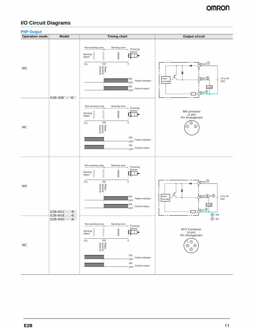
I/O Circuit Diagrams
PNP OutputOperation mode Model Timing chart Output circuit
NO
E2B-S08@-@-B@
NC
NO
E2B-M12@-@-B@E2B-M18@-@-B@E2B-M30@-@-B@
NC
Sensingobject
(%) 100 0Rated
sensingdistance
Sensing zoneNon-sensing zoneProximity Sensor
ONOFFONOFF
Yellow indicator
Control output
314
M8 connector(3 pin)
Pin Arrangement
Load
Brown
Black
Blue
10 to 30 VDC
maincircuits
1
3
4
(%) 100 0
Sensingobject
Rated
sensingdistance
Sensing zoneNon-sensing zoneProximity Sensor
ONOFFONOFF
Yellow indicator
Control output
Sensingobject
(%) 100 0Rated
sensingdistance
Sensing zoneNon-sensing zoneProximity Sensor
ONOFFONOFF
Yellow indicator
Control output
3
12 4
M12 Connector(4 pin)
Pin Arrangement
Brown
Black or
Blue
10 to 30 VDC
: NO
: NC
maincircuits
1
2
4
3
4
2
Load
(%) 100 0
Sensingobject
Rated
sensingdistance
Sensing zoneNon-sensing zoneProximity Sensor
ONOFFONOFF
Yellow indicator
Control output
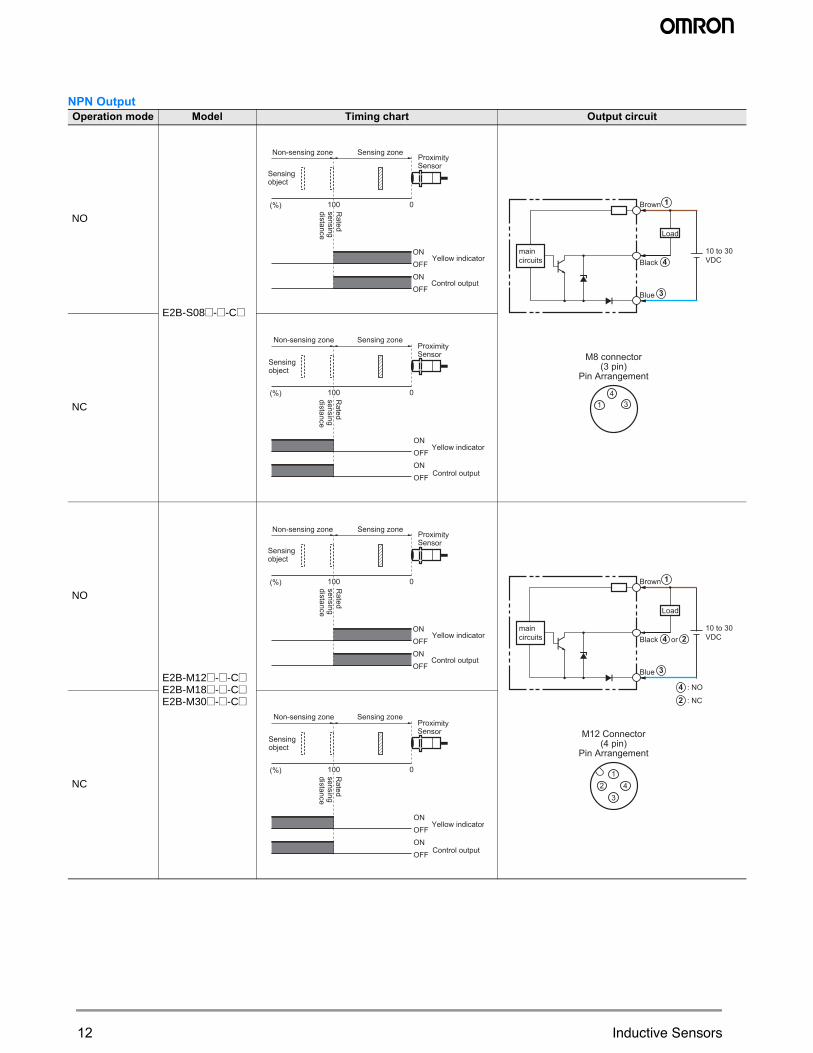
NPN OutputOperation mode Model Timing chart Output circuit
NO
E2B-S08@-@-C@
NC
NO
E2B-M12@-@-C@E2B-M18@-@-C@E2B-M30@-@-C@
NC
Sensingobject
(%) 100 0Rated
sensingdistance
Sensing zoneNon-sensing zoneProximity Sensor
ONOFFONOFF
Yellow indicator
Control output
314
M8 connector(3 pin)
Pin Arrangement
Brown
Black
Blue
10 to 30 VDC
maincircuits
1
3
4
Load
(%) 100 0
Sensingobject
Rated
sensingdistance
Sensing zoneNon-sensing zoneProximity Sensor
ONOFFONOFF
Yellow indicator
Control output
Sensingobject
(%) 100 0Rated
sensingdistance
Sensing zoneNon-sensing zoneProximity Sensor
ONOFFONOFF
Yellow indicator
Control output
3
12 4
M12 Connector(4 pin)
Pin Arrangement
Brown
Black
Blue
10 to 30 VDC
maincircuits
1
3
4 or 2
Load
: NO
: NC
42
(%) 100 0
Sensingobject
Rated
sensingdistance
Sensing zoneNon-sensing zoneProximity Sensor
ONOFFONOFF
Yellow indicator
Control output
12 Inductive Sensors
13E2B
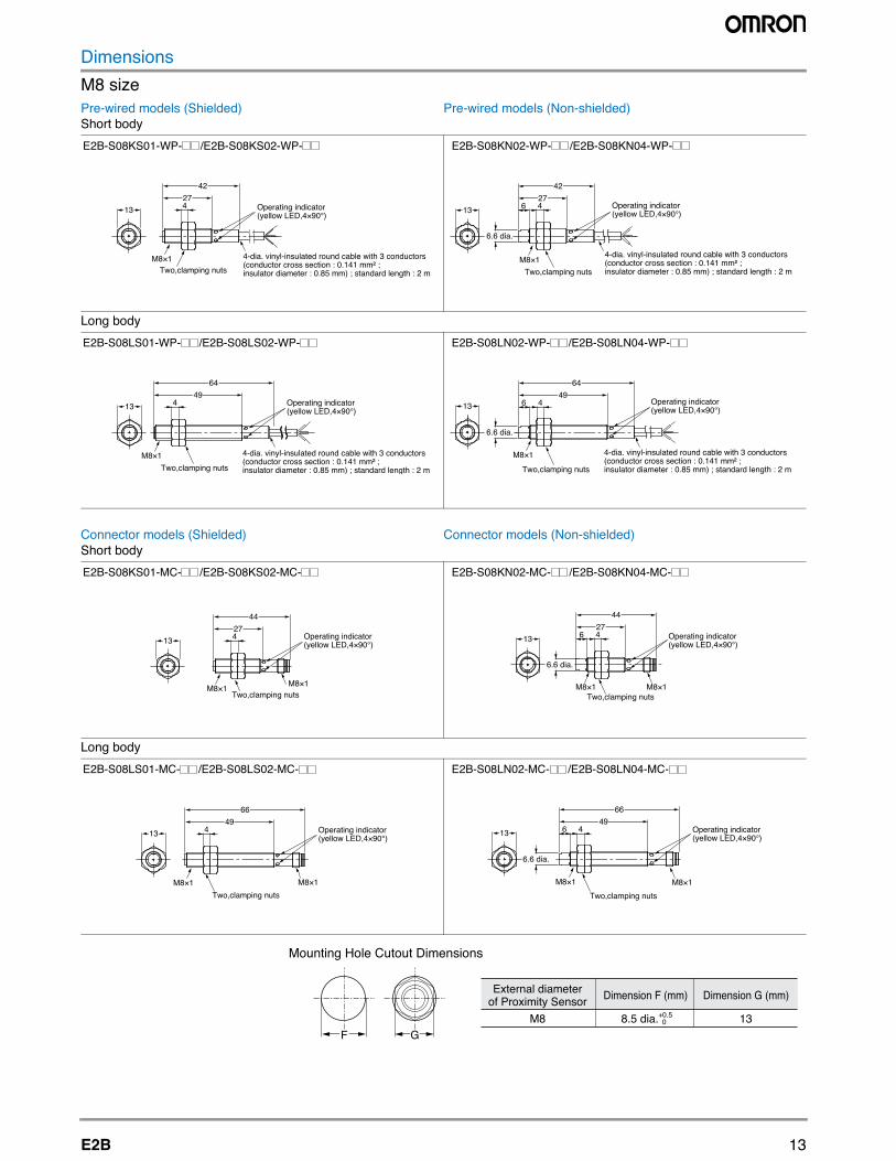
DimensionsM8 sizePre-wired models (Shielded)Short body
Pre-wired models (Non-shielded)
Long body
Connector models (Shielded)Short body
Connector models (Non-shielded)
Long body
M8×1Two,clamping nuts
Operating indicator(yellow LED,4×90°)
4-dia. vinyl-insulated round cable with 3 conductors (conductor cross section : 0.141 mm² ; insulator diameter : 0.85 mm) ; standard length : 2 m
13274
42
E2B-S08KS01-WP- /E2B-S08KS02-WP-
M8×1
Operating indicator(yellow LED,4×90°)
Two,clamping nuts
4-dia. vinyl-insulated round cable with 3 conductors (conductor cross section : 0.141 mm² ; insulator diameter : 0.85 mm) ; standard length : 2 m
6274
42
6.6 dia.
13
E2B-S08KN02-WP- /E2B-S08KN04-WP-
M8×1Two,clamping nuts
Operating indicator(yellow LED,4×90°)
4-dia. vinyl-insulated round cable with 3 conductors (conductor cross section : 0.141 mm² ; insulator diameter : 0.85 mm) ; standard length : 2 m
1349
4
64
E2B-S08LS01-WP- /E2B-S08LS02-WP-
M8×1
Two,clamping nuts
Operating indicator(yellow LED,4×90°)
4-dia. vinyl-insulated round cable with 3 conductors (conductor cross section : 0.141 mm² ; insulator diameter : 0.85 mm) ; standard length : 2 m
13
6.6 dia.
494
64
6
E2B-S08LN02-WP- /E2B-S08LN04-WP-
M8×1Two,clamping nuts
Operating indicator(yellow LED,4×90°)
M8×1
274
44
13
E2B-S08KS01-MC- /E2B-S08KS02-MC-
13
M8×1Two,clamping nuts
M8×1
Operating indicator (yellow LED,4×90°)
6
44274
6.6 dia.
E2B-S08KN02-MC- /E2B-S08KN04-MC-
M8×1
Operating indicator(yellow LED,4×90°)
Two,clamping nutsM8×1
1349
4
66
E2B-S08LS01-MC- /E2B-S08LS02-MC-
M8×1
Operating indicator(yellow LED,4×90°)
Two,clamping nutsM8×1
1349
4
66
6
6.6 dia.
E2B-S08LN02-MC- /E2B-S08LN04-MC-
Mounting Hole Cutout Dimensions
External diameterof Proximity Sensor Dimension F (mm) Dimension G (mm)
M8GF
8.5 dia.+0.5 0 13
14 Inductive Sensors
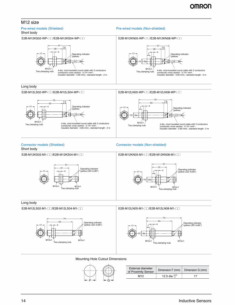
M12 sizePre-wired models (Shielded)Short body
Pre-wired models (Non-shielded)
Long body
Connector models (Shielded)Short body
Connector models (Non-shielded)
Long body
17 Operating indicator(yellow)
30 7.947
4
4-dia. vinyl-insulated round cable with 3 conductors (conductor cross section : 0.141 mm² ; insulator diameter : 0.85 mm) ; standard length : 2 m
M12×1Two,clamping nuts
E2B-M12KS02-WP- /E2B-M12KS04-WP-
17 7
30 7.947
4
10.5 dia.
4-dia. vinyl-insulated round cable with 3 conductors (conductor cross section : 0.141 mm² ; insulator diameter : 0.85 mm) ; standard length : 2 m
M12×1Two,clamping nuts
Operating indicator(yellow)
E2B-M12KN05-WP- /E2B-M12KN08-WP-
17 Operating indicator(yellow)
53 7.970
4
4-dia. vinyl-insulated round cable with 3 conductors (conductor cross section : 0.141 mm² ; insulator diameter : 0.85 mm) ; standard length : 2 m
M12×1Two,clamping nuts
E2B-M12LS02-WP- /E2B-M12LS04-WP-
17 Operating indicator(yellow)
7
53 7.970
4
10.5 dia.
4-dia. vinyl-insulated round cable with 3 conductors (conductor cross section : 0.141 mm² ; insulator diameter : 0.85 mm) ; standard length : 2 m
M12×1Two,clamping nuts
E2B-M12LN05-WP- /E2B-M12LN08-WP-
M12×1M12×1Two,clamping nuts
Operating indicator(yellow LED 4×90°)
3151
417
E2B-M12KS02-M1- /E2B-M12KS04-M1-
M12×1M12×1Two,clamping nuts
Operating indicator(yellow LED 4×90°)7
3151
417
10.5 dia.
E2B-M12KN05-M1- /E2B-M12KN08-M1-
17
M12×1M12×1Two,clamping nuts
Operating indicator(yellow LED 4×90°)
5474
4
E2B-M12LS02-M1- /E2B-M12LS04-M1-
17
M12×1 M12×1Two,clamping nuts
Operating indicator(yellow LED 4×90°)7
5474
4
10.5 dia.
E2B-M12LN05-M1- /E2B-M12LN08-M1-
Mounting Hole Cutout Dimensions
External diameterof Proximity Sensor Dimension F (mm) Dimension G (mm)
M12GF
12.5 dia.+0.5 0 17
15E2B
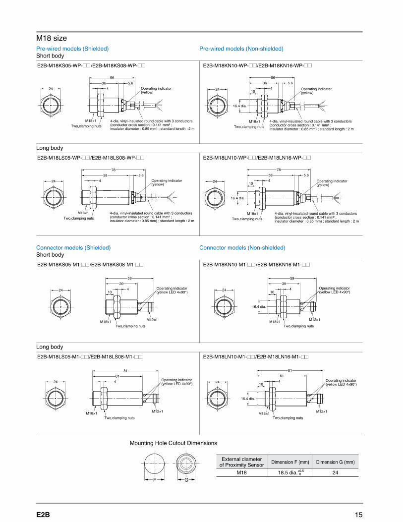
M18 sizePre-wired models (Shielded)Short body
Pre-wired models (Non-shielded)
Long body
Connector models (Shielded)Short body
Connector models (Non-shielded)
Long body
24
4-dia. vinyl-insulated round cable with 3 conductors (conductor cross section : 0.141 mm² ; insulator diameter : 0.85 mm) ; standard length : 2 m
Operating indicator(yellow)
36 5.656
4
M18×1Two,clamping nuts
E2B-M18KS05-WP- /E2B-M18KS08-WP-
4-dia. vinyl-insulated round cable with 3 conductors (conductor cross section : 0.141 mm² ; insulator diameter : 0.85 mm) ; standard length : 2 m
24 Operating indicator(yellow)10
36 5.656
4
16.4 dia.
M18×1Two,clamping nuts
E2B-M18KN10-WP- /E2B-M18KN16-WP-
24
4-dia. vinyl-insulated round cable with 3 conductors (conductor cross section : 0.141 mm² ; insulator diameter : 0.85 mm) ; standard length : 2 m
Operating indicator(yellow)
58 5.678
4
M18×1Two,clamping nuts
E2B-M18LS05-WP- /E2B-M18LS08-WP-
24
4-dia. vinyl-insulated round cable with 3 conductors (conductor cross section : 0.141 mm² ; insulator diameter : 0.85 mm) ; standard length : 2 m
Operating indicator(yellow)10
58 5.678
4
16.4 dia.
M18×1Two,clamping nuts
E2B-M18LN10-WP- /E2B-M18LN16-WP-
24
M12×1M18×1Two,clamping nuts
10
3959
4 Operating indicator(yellow LED 4×90°)
E2B-M18KS05-M1- /E2B-M18KS08-M1-
M12×1M18×1Two,clamping nuts
Operating indicator(yellow LED 4×90°)10
3959
424
16.4 dia.
E2B-M18KN10-M1- /E2B-M18KN16-M1-
24
M12×1M18×1Two,clamping nuts
6181
4 Operating indicator(yellow LED 4×90°)
E2B-M18LS05-M1- /E2B-M18LS08-M1-
24
M12×1M18×1Two,clamping nuts
10
6181
4 Operating indicator(yellow LED 4×90°)
16.4 dia.
E2B-M18LN10-M1- /E2B-M18LN16-M1-
Mounting Hole Cutout Dimensions
External diameterof Proximity Sensor Dimension F (mm) Dimension G (mm)
M18GF
18.5 dia.+0.5 0 24
16 Inductive Sensors
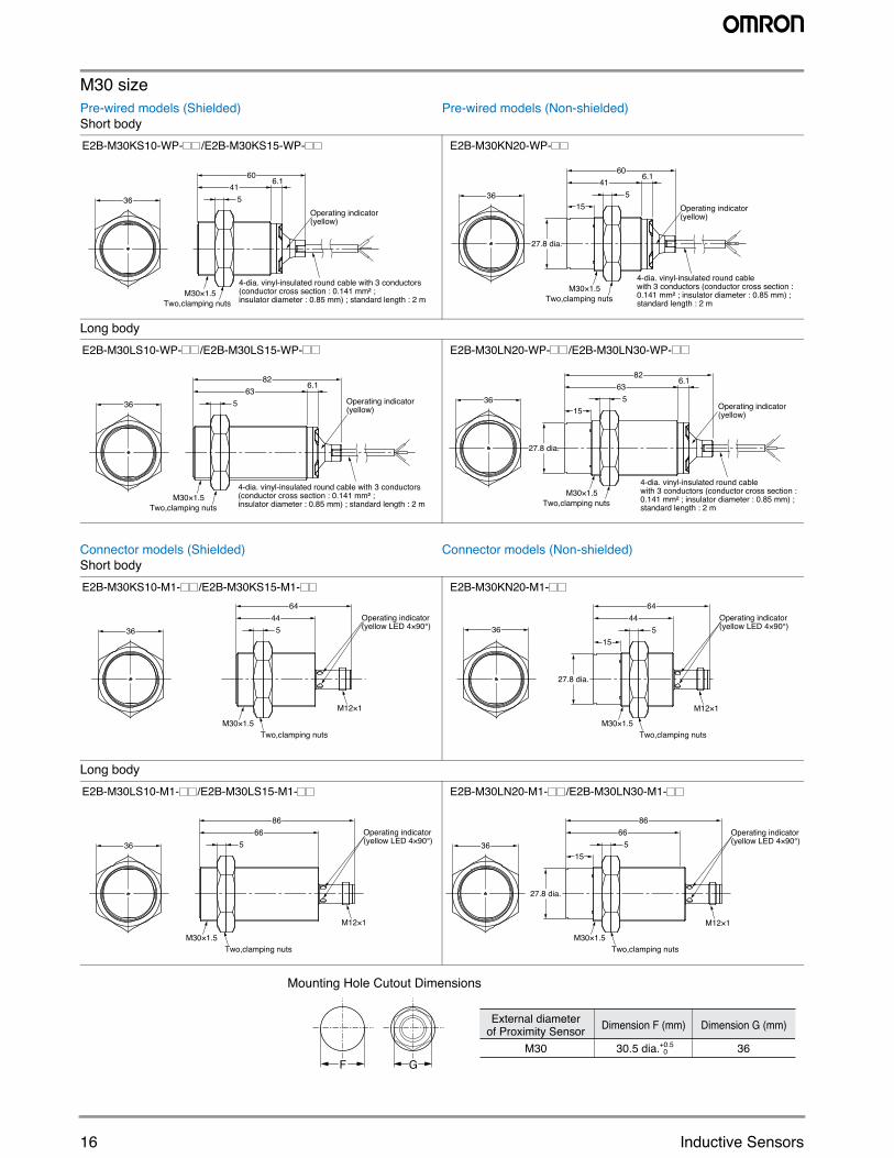
M30 sizePre-wired models (Shielded)Short body
Pre-wired models (Non-shielded)
Long body
Connector models (Shielded)Short body
Connector models (Non-shielded)
Long body
36
M30×1.5Two,clamping nuts
Operating indicator(yellow)
4160
5
4-dia. vinyl-insulated round cable with 3 conductors (conductor cross section : 0.141 mm² ; insulator diameter : 0.85 mm) ; standard length : 2 m
6.1
E2B-M30KS10-WP- /E2B-M30KS15-WP-
M30×1.5Two,clamping nuts
Operating indicator(yellow)
15
4160
536
4-dia. vinyl-insulated round cable with 3 conductors (conductor cross section : 0.141 mm² ; insulator diameter : 0.85 mm) ; standard length : 2 m
6.1
27.8 dia.
E2B-M30KN20-WP-
36
M30×1.5Two,clamping nuts
4-dia. vinyl-insulated round cable with 3 conductors (conductor cross section : 0.141 mm² ; insulator diameter : 0.85 mm) ; standard length : 2 m
6382
5
6.1
Operating indicator(yellow)
E2B-M30LS10-WP- /E2B-M30LS15-WP-
36
M30×1.5Two,clamping nuts
Operating indicator(yellow)15
6382
5
4-dia. vinyl-insulated round cable with 3 conductors (conductor cross section : 0.141 mm² ; insulator diameter : 0.85 mm) ; standard length : 2 m
6.1
27.8 dia.
E2B-M30LN20-WP- /E2B-M30LN30-WP-
M12×1
M30×1.5Two,clamping nuts
Operating indicator(yellow LED 4×90°)
4464
536
E2B-M30KS10-M1- /E2B-M30KS15-M1-
M12×1
M30×1.5Two,clamping nuts
Operating indicator(yellow LED 4×90°)
15
4464
536
27.8 dia.
E2B-M30KN20-M1-
M12×1
M30×1.5Two,clamping nuts
Operating indicator(yellow LED 4×90°)36
6686
5
E2B-M30LS10-M1- /E2B-M30LS15-M1-
M12×1
M30×1.5Two,clamping nuts
Operating indicator(yellow LED 4×90°)36
15
6686
5
27.8 dia.
E2B-M30LN20-M1- /E2B-M30LN30-M1-
Mounting Hole Cutout Dimensions
External diameterof Proximity Sensor Dimension F (mm) Dimension G (mm)
M30GF
30.5 dia.+0.5 0 36
17E2B
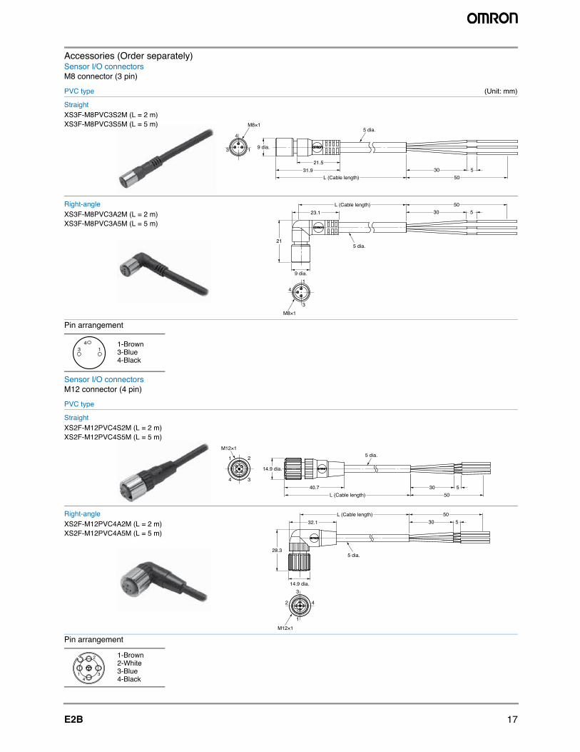
Accessories (Order separately)Sensor I/O connectorsM8 connector (3 pin)
PVC type (Unit: mm)
Pin arrangement
Sensor I/O connectorsM12 connector (4 pin)
PVC type
Pin arrangement
1-Brown3-Blue4-Black
1-Brown2-White3-Blue4-Black
13
4
9 dia.
5030 531.9
L (Cable length)
21.5
5 dia.M8×1
StraightXS3F-M8PVC3S2M (L = 2 m)XS3F-M8PVC3S5M (L = 5 m)
1
3
4
9 dia.
21
5030 523.1
L (Cable length)
M8×1
5 dia.
Right-angleXS3F-M8PVC3A2M (L = 2 m)XS3F-M8PVC3A5M (L = 5 m)
3 14
StraightXS2F-M12PVC4S2M (L = 2 m)XS2F-M12PVC4S5M (L = 5 m)
14.9 dia.
5030 540.7
L (Cable length)
1
3
2
4
5 dia.M12×1
Right-angleXS2F-M12PVC4A2M (L = 2 m)XS2F-M12PVC4A5M (L = 5 m)
14.9 dia.
28.3
503032.1
L (Cable length)
1
3
2 4
5
5 dia.
M12×1
2
14
3
18 Inductive Sensors
Precautions
This product is not designed or rated for ensuring safety of persons. Do not use it for such purposes.
Never use this product with an AC power supply.Otherwise, explosion may result.
Safety precautionsLoad short-circuitDo not short-circuit the load, or the E2B may be damaged. The E2B’s short-circuit protection function will be valid if the polarity of the supply voltage imposed is correct and within the rated voltage range.
WiringBe sure to wire the E2B and load correctly, otherwise it may be dam-aged.
Connection with no loadBe sure to insert loads when wiring. Make sure to connect a proper load to the E2B in operation, otherwise it may damage internal ele-ments.
Do not expose the product to flammable or explosive gases.Do not disassemble, repair, or modify the product.
Correct useDesigningPower reset timeThe Proximity Sensor is ready to operate within 100 ms after power is supplied. If power supplies are connected to the Proximity Sensor and load respectively, be sure to supply power to the Proximity Sen-sor before supplying power to the load.
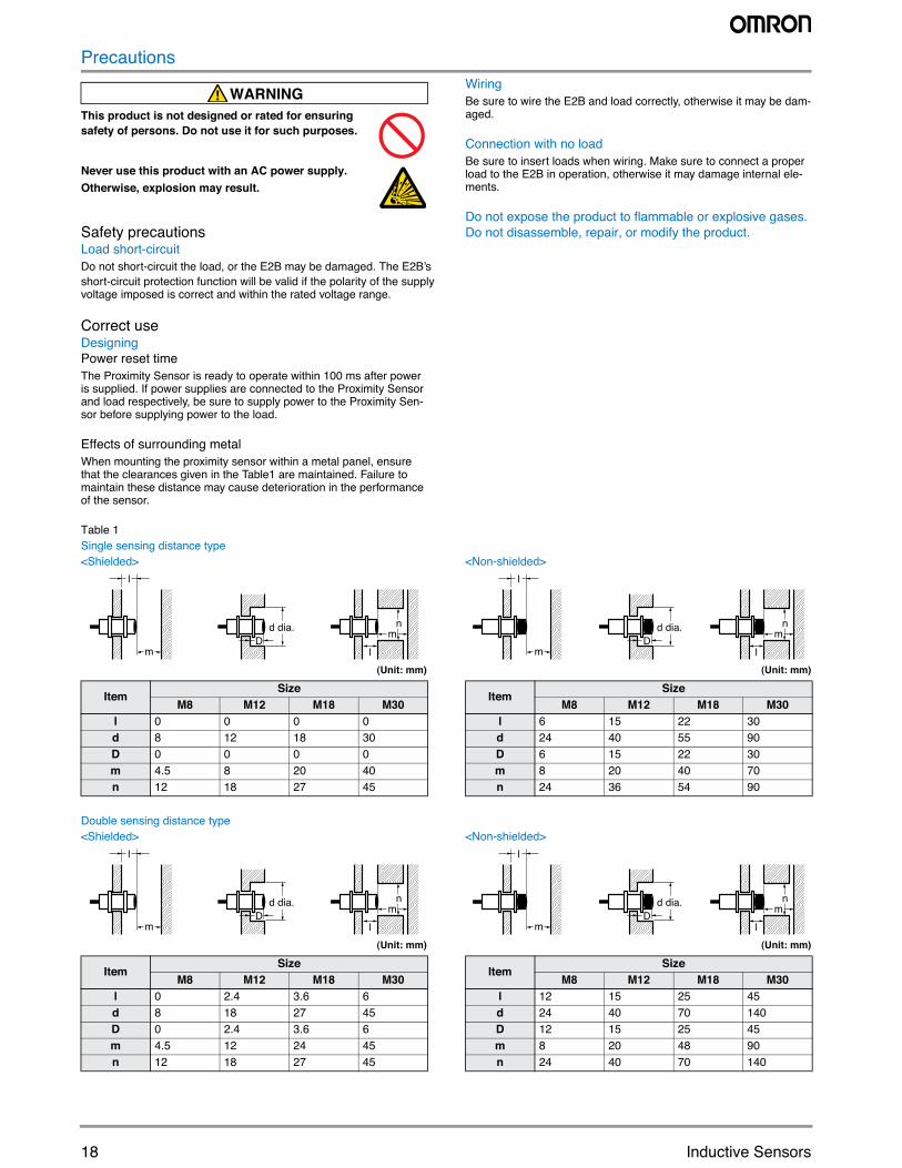
Effects of surrounding metalWhen mounting the proximity sensor within a metal panel, ensure that the clearances given in the Table1 are maintained. Failure to maintain these distance may cause deterioration in the performance of the sensor.
Table 1Single sensing distance type<Shielded>
(Unit: mm)
<Non-shielded>
(Unit: mm)
Double sensing distance type<Shielded>
(Unit: mm)
<Non-shielded>
(Unit: mm)
WARNING
ItemSize
M8 M12 M18 M30l 0 0 0 0d 8 12 18 30D 0 0 0 0m 4.5 8 20 40n 12 18 27 45
lm
n
mD
d dia.
l
ItemSize
M8 M12 M18 M30l 6 15 22 30d 24 40 55 90D 6 15 22 30m 8 20 40 70n 24 36 54 90
lm
n
mD
d dia.
l
ItemSize
M8 M12 M18 M30l 0 2.4 3.6 6d 8 18 27 45D 0 2.4 3.6 6m 4.5 12 24 45n 12 18 27 45
lm
n
mD
d dia.
l
ItemSize
M8 M12 M18 M30l 12 15 25 45d 24 40 70 140D 12 15 25 45m 8 20 48 90n 24 40 70 140
lm
n
mD
d dia.
l
19E2B
Power OFFThe Proximity Sensor may output a pulse signal when it is turned OFF. Therefore, it is recommended that the load be turned OFF before turning OFF the Proximity Sensor.
Power supply transformerWhen using a DC power supply, make sure that the DC power supply has an insulated transformer. Do not use a DC power supply with an auto-transformer.
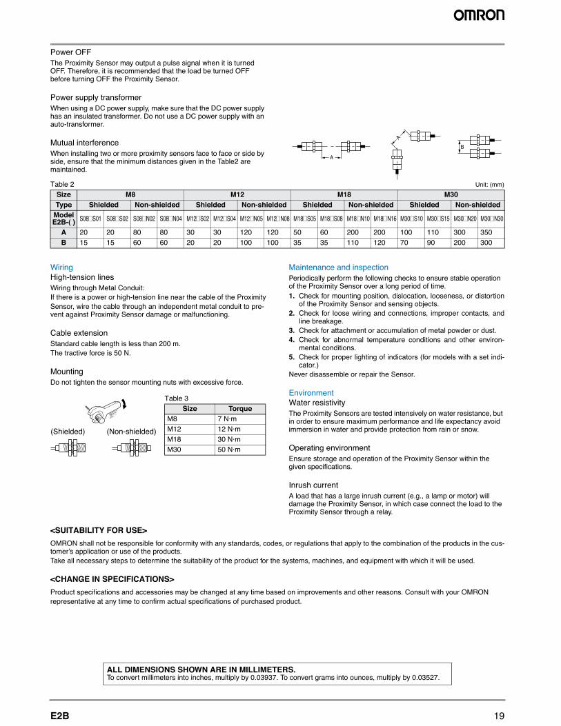
Mutual interferenceWhen installing two or more proximity sensors face to face or side by side, ensure that the minimum distances given in the Table2 are maintained.
Table 2 Unit: (mm)
WiringHigh-tension linesWiring through Metal Conduit:If there is a power or high-tension line near the cable of the ProximitySensor, wire the cable through an independent metal conduit to pre-vent against Proximity Sensor damage or malfunctioning.
Cable extensionStandard cable length is less than 200 m.The tractive force is 50 N.
MountingDo not tighten the sensor mounting nuts with excessive force.
Maintenance and inspectionPeriodically perform the following checks to ensure stable operation of the Proximity Sensor over a long period of time.1. Check for mounting position, dislocation, looseness, or distortion
of the Proximity Sensor and sensing objects.2. Check for loose wiring and connections, improper contacts, and
line breakage.3. Check for attachment or accumulation of metal powder or dust.4. Check for abnormal temperature conditions and other environ-
mental conditions.5. Check for proper lighting of indicators (for models with a set indi-
cator.)Never disassemble or repair the Sensor.
EnvironmentWater resistivityThe Proximity Sensors are tested intensively on water resistance, but in order to ensure maximum performance and life expectancy avoid immersion in water and provide protection from rain or snow.
Operating environmentEnsure storage and operation of the Proximity Sensor within the given specifications.
Inrush currentA load that has a large inrush current (e.g., a lamp or motor) will damage the Proximity Sensor, in which case connect the load to the Proximity Sensor through a relay.
<SUITABILITY FOR USE>OMRON shall not be responsible for conformity with any standards, codes, or regulations that apply to the combination of the products in the cus-tomer’s application or use of the products.Take all necessary steps to determine the suitability of the product for the systems, machines, and equipment with which it will be used.
<CHANGE IN SPECIFICATIONS>Product specifications and accessories may be changed at any time based on improvements and other reasons. Consult with your OMRONrepresentative at any time to confirm actual specifications of purchased product.
Size M8 M12 M18 M30Type Shielded Non-shielded Shielded Non-shielded Shielded Non-shielded Shielded Non-shielded
Model E2B-( ) S08 S01 S08 S02 S08 N02 S08 N04 M12 S02 M12 S04 M12 N05 M12 N08 M18 S05 M18 S08 M18 N10 M18 N16 M30 S10 M30 S15 M30 N20 M30 N30
A 20 20 80 80 30 30 120 120 50 60 200 200 100 110 300 350B 15 15 60 60 20 20 100 100 35 35 110 120 70 90 200 300
(Shielded) (Non-shielded)
Table 3Size Torque
M8 7 N·mM12 12 N·mM18 30 N·mM30 50 N·m
ALL DIMENSIONS SHOWN ARE IN MILLIMETERS.To convert millimeters into inches, multiply by 0.03937. To convert grams into ounces, multiply by 0.03527.
OMRON CANADA, INC. • HEAD OFFICEToronto, ON, Canada • 416.286.6465 • 866.986.6766 • www.omron247.com
OMRON ELECTRONICS DE MEXICO • HEAD OFFICEMéxico DF • 52.55.59.01.43.00 • 001.800.556.6766 • [email protected]
OMRON ELECTRONICS DE MEXICO • SALES OFFICEApodaca, N.L. • 52.81.11.56.99.20 • 001.800.556.6766 • [email protected]
OMRON ELETRÔNICA DO BRASIL LTDA • HEAD OFFICESão Paulo, SP, Brasil • 55.11.2101.6300 • www.omron.com.br
OMRON ARGENTINA • SALES OFFICECono Sur • 54.11.4783.5300
OMRON CHILE • SALES OFFICESantiago • 56.9.9917.3920
OTHER OMRON LATIN AMERICA SALES54.11.4783.5300
OMRON INDUSTRIAL AUTOMATION • THE AMERICAS HEADQUARTERSSchaumburg, IL USA • 847.843.7900 • 800.556.6766 • www.omron247.com
OMRON EUROpE B.V. • Wegalaan 67-69, NL-2132 JD, Hoofddorp, The Netherlands. • Tel: +31 (0) 23 568 13 00Fax: +31 (0) 23 568 13 88 • www.industrial.omron.eu
Cat. No. E56I-E-01A 08/13 Note: Specifications are subject to change. © 2013 Omron Electronics LLC Printed in U.S.A.
E56I-E-01 Note: Specifications are subject to change. © 2013 Omron Electronics LLC Printed in U.S.A.
Authorized Distributor:
B.V. • Wegalaan 67-69, NL-2132 JD, Hoofddorp, The Netherlands. • Tel: +31 (0) 23 568 13 00 • Fax: +31 (0) 23 568 13 88 • www.industrial.omron.eu
Automation Control Systems• Machine Automation Controllers (MAC) • Programmable Controllers (PLC) • Operator interfaces (HMI) • Distributed I/O • Software
Drives & Motion Controls • Servo & AC Drives • Motion Controllers & Encoders
Temperature & process Controllers • Single and Multi-loop Controllers
Sensors & Vision• Proximity Sensors • Photoelectric Sensors • Fiber-Optic Sensors• Amplified Photomicrosensors • Measurement Sensors• Ultrasonic Sensors • Vision Sensors • RFID/Code Readers
Industrial Components • Relays • Pushbuttons & Indicators • Limit and Basic Switches • Timers • Counters • Metering Devices • Power Supplies
Safety • Laser Scanners • Safety Mats • Edges and Bumpers • Programmable Safety Controllers • Light Curtains • Safety Relays • Safety Interlock Switches


![[50] Reliable Technology of Centimeter GPSGLONASS Surveying in Forest Environments](https://img.pdfslide.net/doc/110x75/577cbfc21a28aba7118e0259/50-reliable-technology-of-centimeter-gpsglonass-surveying-in-forest-environments.jpg)