Embed Size (px)
Citation preview
Relief Systems
11/6/2011 12010 Fall
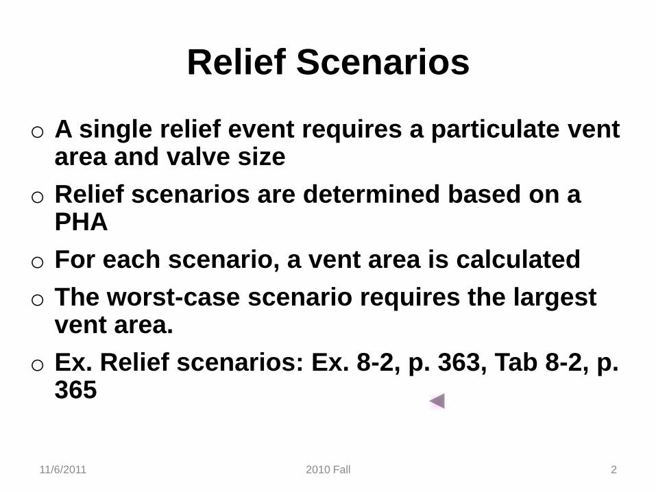
Relief Scenarios
o A single relief event requires a particulate ventarea and valve size
o Relief scenarios are determined based on a PHA
o For each scenario, a vent area is calculated
o The worst-case scenario requires the largest vent area.
o Ex. Relief scenarios: Ex. 8-2, p. 363, Tab 8-2, p. 365
11/6/2011 22010 Fall
11/6/2011 2010 Fall 3
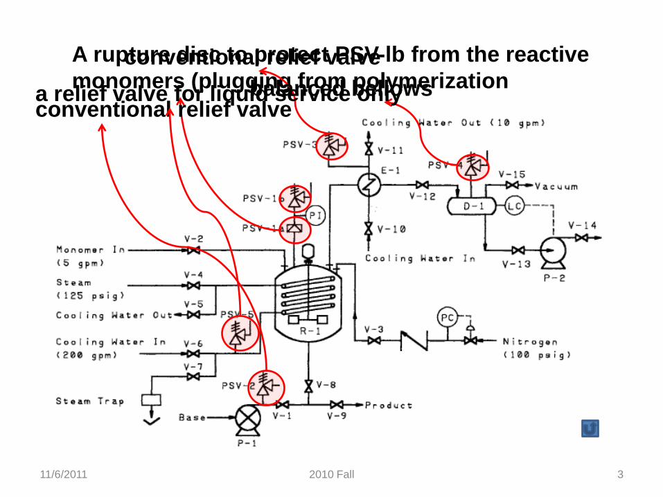
A rupture disc to protect PSV-lb from the reactive
monomers (plugging from polymerization
conventional relief valve
conventional relief valve
balanced bellowsa relief valve for liquid service only
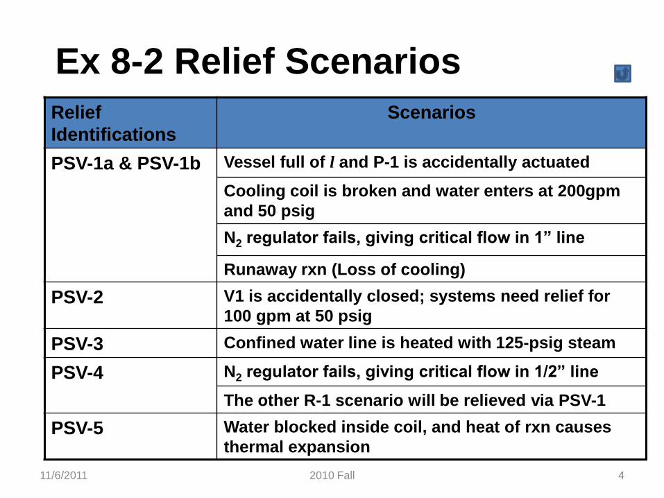
Ex 8-2 Relief Scenarios
Relief
Identifications
Scenarios
PSV-1a & PSV-1b Vessel full of l and P-1 is accidentally actuated
Cooling coil is broken and water enters at 200gpm
and 50 psig
N2 regulator fails, giving critical flow in 1” line
Runaway rxn (Loss of cooling)
PSV-2 V1 is accidentally closed; systems need relief for
100 gpm at 50 psig
PSV-3 Confined water line is heated with 125-psig steam
PSV-4 N2 regulator fails, giving critical flow in 1/2” line
The other R-1 scenario will be relieved via PSV-1
PSV-5 Water blocked inside coil, and heat of rxn causes
thermal expansion
11/6/2011 42010 Fall
Data for Relief Sizing
o Physical property data
o Chemical reaction rate behavior
o Single phase releases: vapor, liquid, solid
o Multiple phase releases
o Runaway reaction relief: liquid & vapor
o Gas or dust explosions from combustion apparatus
o These data are part of the process safety information needed for a PHA
11/6/2011 52010 Fall

Reaction Behavior Measurement
o For accurate relief vent area determinations, experimental data are most important
o Calorimeters are used to characterize behavior during normal reaction or runaway.
o Sample is progressively heated to search for anexothermic reaction
o Raw data includes T, P, time, amount of non condensable gas formed, onset temperature, maximum heat rate, maximum pressure rate
11/6/2011 62010 Fall
11/6/2011 2010 Fall 7
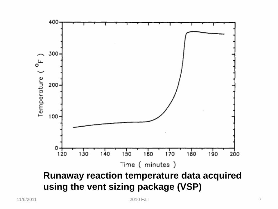
Runaway reaction temperature data acquired
using the vent sizing package (VSP)
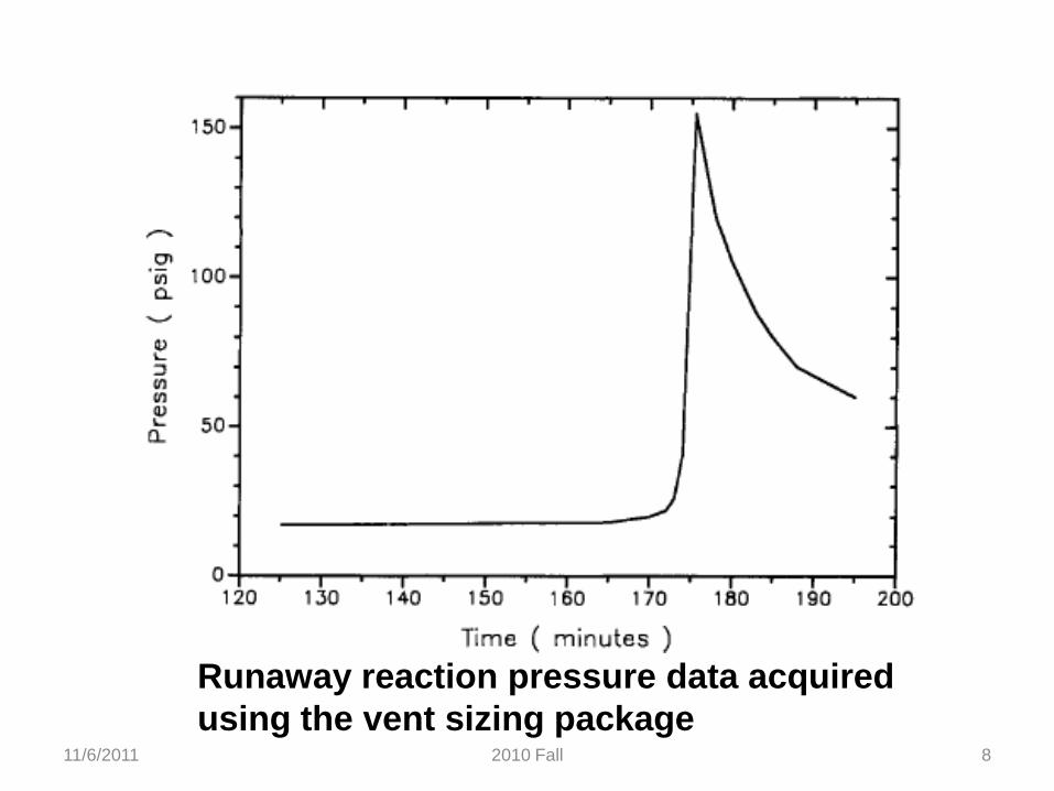
11/6/2011 2010 Fall 8
Runaway reaction pressure data acquired
using the vent sizing package
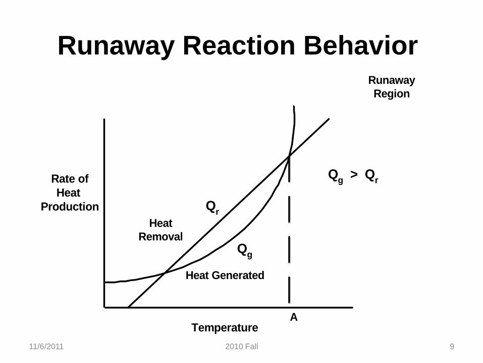
Runaway Reaction Behavior
Heat
Removal
Heat Generated
Runaway
Region
A
Qg
Qr
Qg > Q
rRate of
Heat
Production
Temperature
11/6/2011 92010 Fall
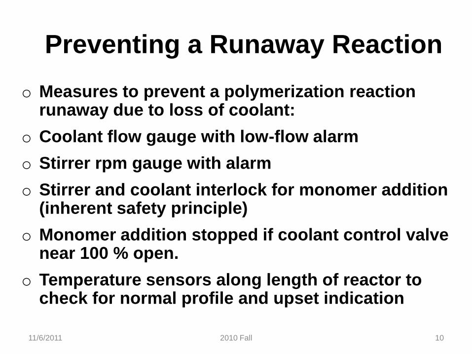
Preventing a Runaway Reaction
o Measures to prevent a polymerization reaction runaway due to loss of coolant:
o Coolant flow gauge with low-flow alarm
o Stirrer rpm gauge with alarm
o Stirrer and coolant interlock for monomer addition(inherent safety principle)
o Monomer addition stopped if coolant control valvenear 100 % open.
o Temperature sensors along length of reactor to check for normal profile and upset indication
11/6/2011 102010 Fall
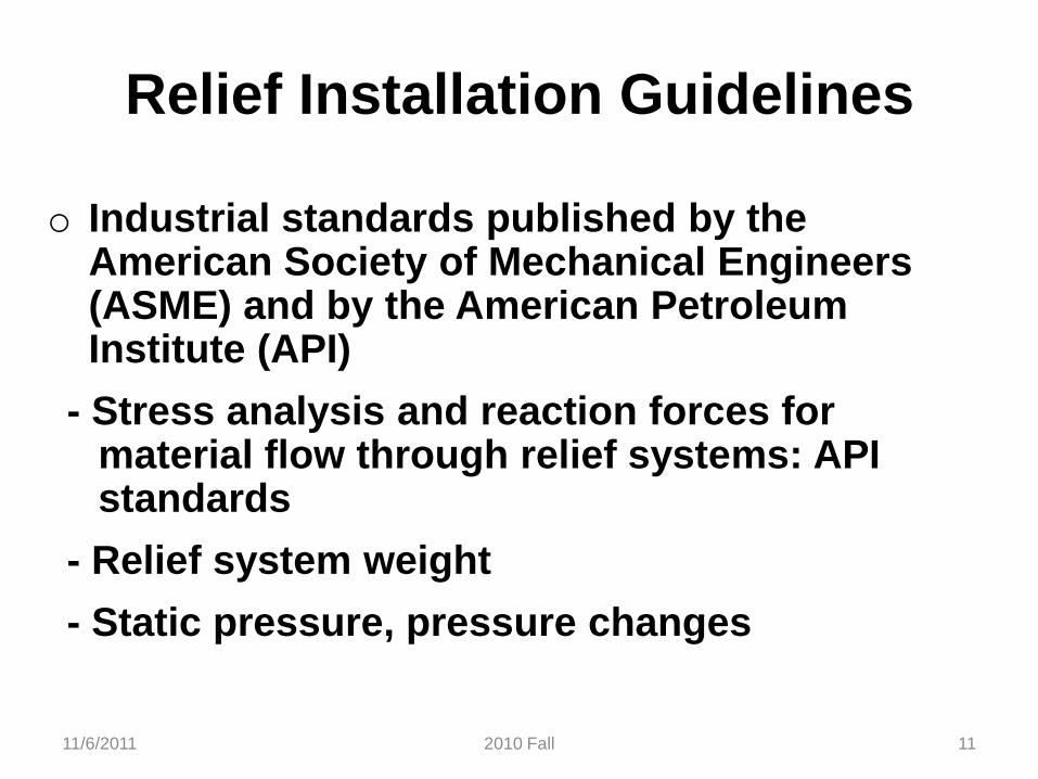
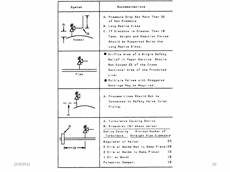
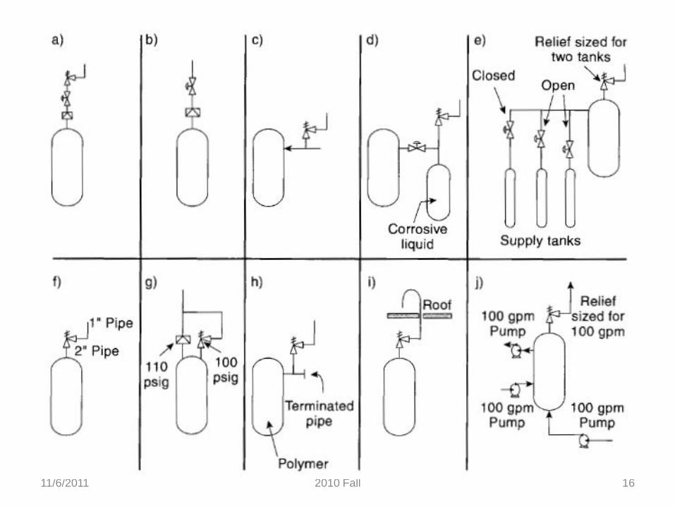
Relief Installation Guidelines
o Industrial standards published by the American Society of Mechanical Engineers (ASME) and by the American Petroleum Institute (API)
- Stress analysis and reaction forces for material flow through relief systems: API standards
- Relief system weight
- Static pressure, pressure changes
11/6/2011 112010 Fall
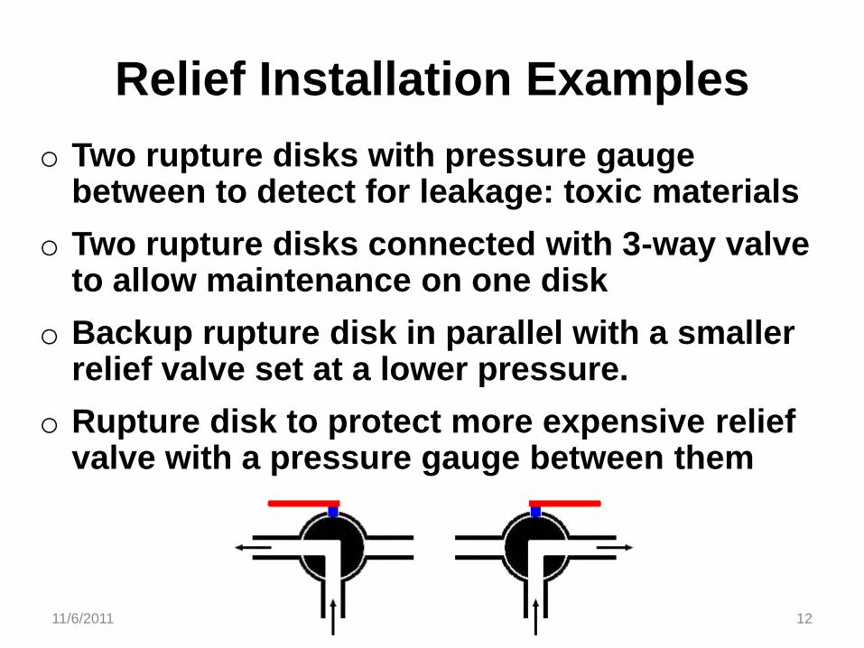
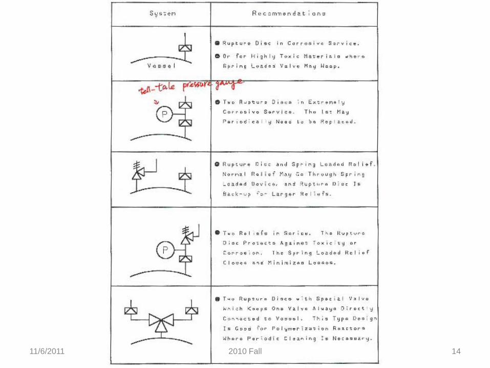
Relief Installation Examples
o Two rupture disks with pressure gauge between to detect for leakage: toxic materials
o Two rupture disks connected with 3-way valveto allow maintenance on one disk
o Backup rupture disk in parallel with a smallerrelief valve set at a lower pressure.
o Rupture disk to protect more expensive reliefvalve with a pressure gauge between them
11/6/2011 122010 Fall
Location Guidelines
o Relief valves on all vessels
o Pressure or vacuum protection for vessels
o Steam jackets
o Pipes between valves
o Pumps, compressors, turbines on discharge
o High pressure connected to low pressure
o Safety/cost balance: relief device vs design for
highest pressure
11/6/2011 132010 Fall
11/6/2011 142010 Fall
11/6/2011 152010 Fall
11/6/2011 162010 Fall
Total Containment Systems
o Relief materials are mostly vented to total containment and treatment systems
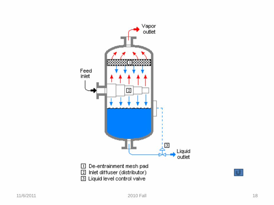
o Knockout: separation of liquid from vapor; coolant for high boiling material (Ex 8-3, p. 374)
o Liquid collected, transferred, incinerated
o Vapor transferred to treatment, e.g., condenser (high boiling), scrubber (toxic),incinerator, flare (combustible, toxic), combination
11/6/2011 172010 Fall
11/6/2011 2010 Fall 18
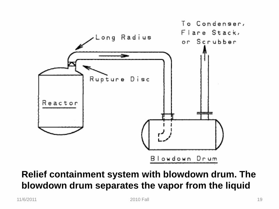
11/6/2011 192010 Fall
Relief containment system with blowdown drum. The
blowdown drum separates the vapor from the liquid
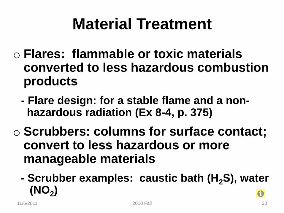
Material Treatment
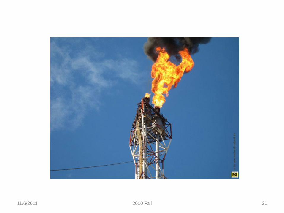
o Flares: flammable or toxic materials converted to less hazardous combustionproducts
- Flare design: for a stable flame and a non-hazardous radiation (Ex 8-4, p. 375)
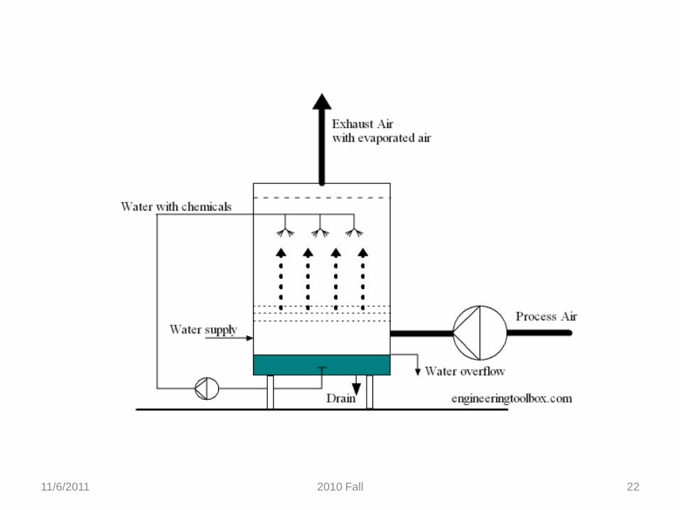
o Scrubbers: columns for surface contact; convert to less hazardous or more manageable materials
- Scrubber examples: caustic bath (H2S), water(NO2)
11/6/2011 202010 Fall
11/6/2011 2010 Fall 21
11/6/2011 2010 Fall 22