Embed Size (px)
Citation preview

Relion 615® series
Motor protection and controlREM615 ANSIProduct guide
ABB 2
1MAC251744 -PG Rev. A
Issued: 03.01.2010
Motor Protection
REM615 ANSI
Product Version 2.0
Contents
Disclaimer
Th e information in this document is subject to change without notice and should not be construed as a commitment by ABB Inc. ABB Inc. assumes no responsibility for any errors that may appear in this document.
Copyright © 2010 ABB
All rights reserved.
Trademarks
ABB is a registered trademark of ABB Group. All other brand or product names mentioned in this document may be trademarks or registered trademarks of their respective holders.
1 Description . . . . . . . . . . . . . . . . . . . . . . . . . . . . . 3
2 Standard confi gurations . . . . . . . . . . . . . . . . 4 - 5
3 Protection functions . . . . . . . . . . . . . . . . . . . . . . 6
4 Application . . . . . . . . . . . . . . . . . . . . . . . . . . . . . 7
5 Supported ABB solutions . . . . . . . . . . . . . . . 8 - 9
6 Control . . . . . . . . . . . . . . . . . . . . . . . . . . . . . . . 10
7 Measurement . . . . . . . . . . . . . . . . . . . . . . . . . . 10
8 Digital fault recorder . . . . . . . . . . . . . . . . . . . . . 10
9 Events recorder . . . . . . . . . . . . . . . . . . . . . . . . 10
10 Fault recorder . . . . . . . . . . . . . . . . . . . . . . . . . 10
11 Circuit-breaker monitoring . . . . . . . . . . . . . . . 11
12 Trip-circuit supervision . . . . . . . . . . . . . . . . . . 11
13 Self-diagnostics . . . . . . . . . . . . . . . . . . . . . . . 11
14 Fuse failure protection . . . . . . . . . . . . . . . . . . 11
15 Current circuit supervision . . . . . . . . . . . . . . . 11
16 Access control . . . . . . . . . . . . . . . . . . . . . . . . 12
17 Inputs and outputs . . . . . . . . . . . . . . . . . . . . . 12
18 Communication . . . . . . . . . . . . . . . . . . . . . . . 13
19 Technical data . . . . . . . . . . . . . . . . . . . . 14 - 32
20 Display options . . . . . . . . . . . . . . . . . . . . . . . . 33
21 Mounting methods . . . . . . . . . . . . . . . . . . . . . 34
22 Relay case and relay plug-in unit . . . . . . . . . . 34
23 Selection and ordering data . . . . . . . . . . . . . . 35
24 Accessories and ordering data. . . . . . . . . . . . 36
25 Tools . . . . . . . . . . . . . . . . . . . . . . . . . . . . . . . . 37
26 Terminal diagrams . . . . . . . . . . . . . . . . . 38 - 39
27 Certifi cates . . . . . . . . . . . . . . . . . . . . . . . . . . . 40
28 References . . . . . . . . . . . . . . . . . . . . . . . . . . . 40
29 Functions, codes and symbols . . . . . . . 41 - 42
30 Document revision history . . . . . . . . . . . . . . . 43
31 Notes . . . . . . . . . . . . . . . . . . . . . . . . . . . 44 - 45

ABB 3
Motor Protection
REM615 ANSI
Product Version 2.0
1MAC251744 -PG Rev. A
Issued: 03.01.2010
1. Description
Th e REM615 is a dedicated motor protection and control IED perfectly aligned for the protection, control, measurement and supervision of asynchronous motors in manufacturing and process industry. REM615 is a member of ABB’s Relion® product family and a part of its 615 protection and control product series. Th e 615 series IEDs are characterized by their compactness and withdrawable design. Engineered from the ground up, the 615 series has been designed to unleash the full potential of the IEC 61850 standard for communication and interoperability between substation automation devices.
Unique REM615 ANSI features
• Four setting groups• Drawout design• Normally-closed output for motor contactors• Dedicated machine-run-time timers• Loss-of-load supervision• Arc fl ash detection (AFD)• Th ermal overload protection of motor• Ring-lug terminals for all inputs and outputs• Large, easy to read LCD screen• Environmentally friendly design with RoHS compliance
Application
Th e REM615 constitutes main protection for asynchronous motors and their drives in manufacturing and process industry. Typically, the motor IED is used with circuit breaker or contactor controlled HV motors, and contactor controlled medium sized and large LV motors in a variety of drives, such as pumps and conveyors, crushers and choppers, mixers and agitators, fans, and aerators. Flexible coding allows for choosing current-only or current-and-voltage confi gurations to best fi t your motor application needs.
Protection and control
REM615 off ers all the functionality needed to manage motor starts and normal drive operations, including protection and fault clearance in abnormal situations. Th e main features of the motor IED include thermal overload protection, motor start-up time supervision, locked rotor protection, and protection against too frequent motor starts. Furthermore, the IED off ers negative phase sequence current unbalance protection, motor running stall protection, loss-of-load supervision, phase-reversal protection, and a provision to perform a forced emergency start.
REM615 also incorporates non-directional and directional ground-fault protection, back-up overcurrent protection, three phase undervoltage protection, and negative phase sequence overvoltage, and positive sequence undervoltage protection. Enhanced with an optional plug-in card, REM615 off ers a fast three-channel arc-fault protection system for arc fl ash supervision of the switchgear compartments.
REM615 also integrates basic control functionality, which facilitates the control of one circuit breaker via the front panel HMI or through remote controls. To protect the IED from unauthorized access and to maintain the integrity of information, the IED has been provided with a four-level, role-based, user authentication system. Th e access control system applies to the front panel HMI, the web browser based HMI, and the PCM600 Protection, and Control IED Manager.
Standardized communication
REM615 genuinely supports the new IEC 61850 standard for inter-device communication in substations. It also supports the industry standard Modbus® protocol, and the well-established DNP3 and IEC 60870-5-103 protocols.For accurate time stamping, REM615 supports synchronization over Ethernet using SNTP or over a separate bus using IRIG-B.

ABB 4
1MAC251744 -PG Rev. A
Issued: 03.01.2010
Motor Protection
REM615 ANSI
Product Version 2.0
2. Standard confi gurations
Th e REM615 relay main application is protection, control, metering and monitoring of asynchronous motors and off ers two standard confi gurations whose relay functions and features are based on the analog inputs ordered for each confi guration. See Tables 1 and 2 for details.
Table 1. Standard configurationsDescription Std. confi g. - functional applicationCurrent-based metering and protection ACurrent-based and voltage-based metering and protection C
One confi guration comprises only current analog inputs useful in cost-eff ective motor protection, control and monitoring industrial and utility applications. Th e second confi guration includes the addition of voltage analog inputs for more comprehensive motor protection and control applications. Both confi gurations include standard features of metering, monitoring and control plus sequence of event, fault and digital waveform recording. Advanced Ethernet communications is included standard with parallel support of DNP3.0 Level 2+*, Modbus and IEC61850 and SNTP over TCP/IP. Optional RS-232 and RS-485 serial communication ports are available that support user programmable DNP3.0 Level 2+* or Modbus protocols. Included with the optional serial communication ports is IRIG-B time synchronization.
* The DNP3.0 Level 2+ implementation includes some Level 3 functionality.

ABB 5
Motor Protection
REM615 ANSI
Product Version 2.0
1MAC251744 -PG Rev. A
Issued: 03.01.2010
Included = •, Optional =
Analog Inputs 3 CT + Ground CT
3 CT + Ground CT + 5 VT
Order Code AA CAProtection ANSI
Phase overcurrent, 2 elements 51P, 50P • •
Ground overcurrent 51G • •
Directional neutral overcurrent 67N •
Thermal overload 49M • •
Three-phase undercurrent 37 • •
Phase reversal 46R • •
Locked rotor / start 66/51LRS • •
Locked rotor / jam 51LR • •
Negative sequence overcurrent, 2 elements 46M-1, 46M-2 • •
Phase undervoltage 27 •
Phase sequence overvoltage 47 •
Ground overvoltage 59G •
Circuit breaker failure 50BF • •
Electrically latched/self-resetting trip output, 2 elements 86/94-1,86/94-2 • •
Arc flash detection via three lens sensors AFD-1, AFD-2, AFD-3
ControlCircuit breaker control 52 • •
Emergency start 62EST • •
Monitoring and SupervisionTrip circuit monitoring TCM • •
Breaker condition monitoring 52CM • •
Fuse failure 60 •
Open CT secondary monitoring CCM • •
Machine run timer, 2 elements OPTM-1, OPTM-2 • •
MeasurementsThree-phase currents IA, IB, IC • •
Sequence currents I1, I2, I0 • •
Ground current IG • •
Demand phase currents • •
Maximum demand phase currents • •
Three-phase voltages VA, VB, VC •
Sequence voltages V1, V2, V0 •
Ground voltage VG •
Power, energy, and power factor P, E, and PF •
Automation & Communications10/100 BaseT Ethernet (RJ45) • •
100 BaseFL Ethernet(LC)
10/100 BaseT Ethernet(RJ45) + RS-485(1x4-wire or 2x2-wire) + IRIG-B
100 BaseFL Ethernet(LC) + RS-485(1x4-wire or 2x2-wire) +
IRIG-B
Ethernet 10/100 BaseT (RJ45) + confi gurable RS232/RS485 + [RS485 or serial glass fi ber (ST)] + IRIG-B
RecordsSequence of events recorder SER • •
Fault recorder FLR • •
Digital fault (waveform) recorder DFR • •
Table 2. Functions and features
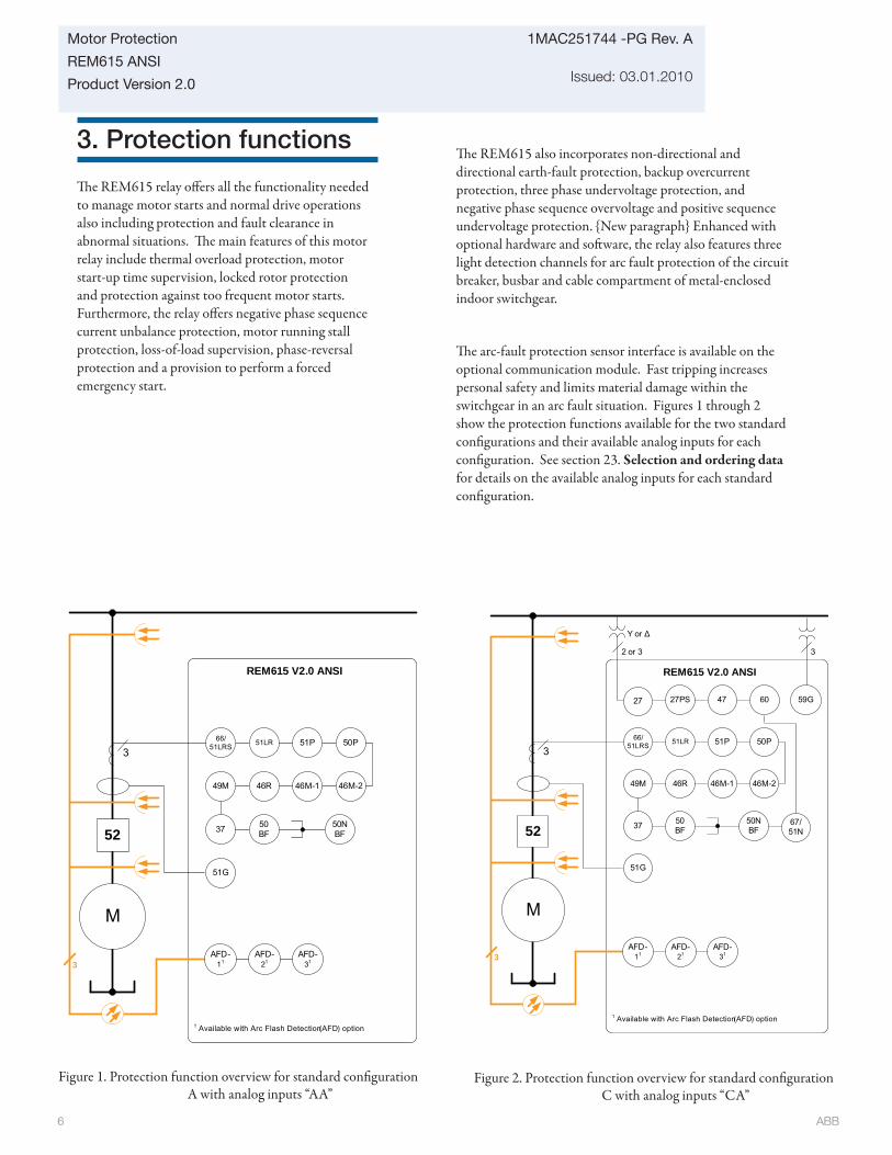
ABB 6
1MAC251744 -PG Rev. A
Issued: 03.01.2010
Motor Protection
REM615 ANSI
Product Version 2.0
3. Protection functions
Th e REM615 relay off ers all the functionality needed to manage motor starts and normal drive operations also including protection and fault clearance in abnormal situations. Th e main features of this motor relay include thermal overload protection, motor start-up time supervision, locked rotor protection and protection against too frequent motor starts. Furthermore, the relay off ers negative phase sequence current unbalance protection, motor running stall protection, loss-of-load supervision, phase-reversal protection and a provision to perform a forced emergency start.
Figure 2. Protection function overview for standard confi guration C with analog inputs “CA”
3
REM615 V2.0 ANSI
M
37
66/51LRS 51LR 51P 50P
46R49M 46M-1
87
2 or 3
Υ or Δ
59G
3
27 27PS
67/51N
46M-2
50BF
50NBF52
51G
1 Available with Arc Flash Detection (AFD) option
3AFD-
31AFD-
11AFD-
21
6047
Figure 1. Protection function overview for standard confi guration A with analog inputs “AA”
3
REM615 V2.0 ANSI
M
37
66/51LRS 51LR 51P 50P
46R49M 46M-1
87
46M-2
50BF
50NBF52
51G
1 Available with Arc Flash Detection (AFD) option
3AFD-
31AFD-
11AFD-
21
Th e REM615 also incorporates non-directional and directional earth-fault protection, backup overcurrent protection, three phase undervoltage protection, and negative phase sequence overvoltage and positive sequence undervoltage protection. {New paragraph} Enhanced with optional hardware and soft ware, the relay also features three light detection channels for arc fault protection of the circuit breaker, busbar and cable compartment of metal-enclosed indoor switchgear.
Th e arc-fault protection sensor interface is available on the optional communication module. Fast tripping increases personal safety and limits material damage within the switchgear in an arc fault situation. Figures 1 through 2 show the protection functions available for the two standard confi gurations and their available analog inputs for each confi guration. See section 23. Selection and ordering data for details on the available analog inputs for each standard confi guration.
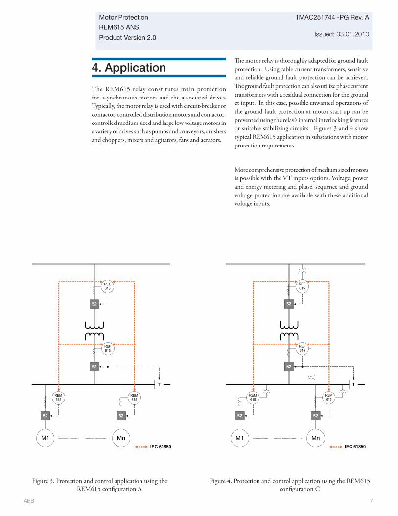
ABB 7
Motor Protection
REM615 ANSI
Product Version 2.0
1MAC251744 -PG Rev. A
Issued: 03.01.2010
4. Application
The REM615 relay constitutes main protection for asynchronous motors and the associated drives. Typically, the motor relay is used with circuit-breaker or contactor-controlled distribution motors and contactor-controlled medium sized and large low voltage motors in a variety of drives such as pumps and conveyors, crushers and choppers, mixers and agitators, fans and aerators.
Th e motor relay is thoroughly adapted for ground fault protection. Using cable current transformers, sensitive and reliable ground fault protection can be achieved. Th e ground fault protection can also utilize phase current transformers with a residual connection for the ground ct input. In this case, possible unwanted operations of the ground fault protection at motor start-up can be prevented using the relay’s internal interlocking features or suitable stabilizing circuits. Figures 3 and 4 show typical REM615 application in substations with motor protection requirements.
More comprehensive protection of medium sized motors is possible with the VT inputs options. Voltage, power and energy metering and phase, sequence and ground voltage protection are available with these additional voltage inputs.
Figure 3. Protection and control application using the REM615 confi guration A
Figure 4. Protection and control application using the REM615 confi guration C
52
52
52
T
IEC 61850
52
REM615
REM615
REF615
REF615
M1 Mn
52
52
52
T
52
REM615
REM615
REF615
REF615
IEC 61850
M1 Mn

ABB 8
1MAC251744 -PG Rev. A
Issued: 03.01.2010
Motor Protection
REM615 ANSI
Product Version 2.0
5. Supported ABB solutions
ABB’s 615 series protection and control IEDs together with the COM600 Station Automation device constitute a genuine IEC 61850 solution for reliable power distribution in utility and industrial power systems. To facilitate and streamline the system engineering ABB’s IEDs are supplied with Connectivity Packages containing a compilation of soft ware and IED-specifi c information including single-line diagram templates, a full IED data model including event and parameter lists. By utilizing the Connectivity Packages the IEDs can be readily confi gured via the PCM600 Protection and Control IED Manager and integrated with the COM600 Station Automation device or the MicroSCADA Pro network control and management system.
Th e 615 series IEDs off er native support for the IEC 61850 standard also including horizontal GOOSE messaging. Compared with traditional hard-wired inter-device signaling, peer-to-peer communication over a switched Ethernet LAN off ers an advanced and versatile platform for power system protection. Fast soft ware-based communication, continuous supervision of the integrity of the protection and communication system, and inherent fl exibility for reconfi guration and upgrades are among the distinctive features of the protection system approach enabled by the full implementation of the IEC 61850 substation automation standard.
At the substation level COM600 utilizes the data content of the design level IEDs to off er enhanced substation level functionality. COM600 features a web-browser based HMI providing a customizable graphical display for visualizing single line mimic diagrams for switchgear design solutions. To enhance personnel safety, the web HMI also enables remote access to substation devices and processes. Furthermore, COM600 can be used as a local data warehouse for technical documentation of the substation and for network data collected by the IEDs. Th e collected network data facilitates extensive reporting and analyzing of network fault situations using the data historian and event handling features of COM600.
COM600 also features gateway functionality providing seamless connectivity between the substation IEDs and network-level control and management systems such as MicroSCADA Pro and System 800xA.
Table 3. Supported ABB solutions
Product VersionStation Automation COM600 3.4 or later
MicroSCADA Pro 9.2 SP1 or later

ABB 9
Motor Protection
REM615 ANSI
Product Version 2.0
1MAC251744 -PG Rev. A
Issued: 03.01.2010
COM600
Peer-to-peer GOOSE communication
Peer-to-peer GOOSE communication
IEC 61850-8-1 IEC 61850-8-1
Ethernet switch PCM600 PCM600
REM615REF615 RET615 RED615
Ethernet switch
RET615RED615 REM615 REF615Fibre optic LD communication
Binary signal transfer
OPC
COM600Web HMI
COM600Web HMI
COM600
Ethernet switch
ABB System 800xA
Peer-to-peer GOOSE communication
IEC 61850-8-1
IEC 60870-5-104
COM600Web HMI
ABBMicroSCADA
Ethernet switch PCM600
REF615RED615 RET615RET615REF615 RED615Fibre optic LD communication
Binary signal transfer
COM600
Peer-to-peer GOOSE communication
IEC 61850-8-1
COM600Web HMI
PCM600Ethernet switch
COM600
Figure 11. Utility distribution network example using 615 series IEDs, Station Automation COM600 and MicroSCADA Pro
Figure 12. Industrial distribution network example using 615 series IEDs, Station Automation COM600 and System 800xA

ABB 10
1MAC251744 -PG Rev. A
Issued: 03.01.2010
Motor Protection
REM615 ANSI
Product Version 2.0
6. Control
Th e relay off ers status and control of one circuit breaker with dedicated push-buttons on the front panel local human machine interface (LHMI) for opening and closing of that breaker. Flexible remote breaker control of select-before-trip (SBO) or direct trip is also available with each of the supported DNP3.0 Level 2+, Modbus and IEC 61850 communication protocols. Interlocking schemes required by the application are confi gured with the signal matrix tool in PCM600 by the application are confi gured with the Signal Matrix Tool (SMT) of the REM615 user tool PCM600.
7. Measurements
Th e relay continuously measures the phase currents, the sequence components of the currents and the residual current. If the relay includes the ground ct option, it also measures the ground current, IG. In addition, the relay calculates the demand phase currents over a user-selectable pre-set time frame, the thermal overload of the protected object, and the phase unbalance value as a ratio between the negative sequence and positive sequence currents. With the VT option, phase, ground and sequence voltage measurements plus power, energy and power factor measurements are included.
Th e values measured can be accessed locally via the user interface on the relay front panel or remotely via the communication interface of the relay. Th e values can also be accessed locally or remotely using the web-browser based user interface.
8. Digital fault recorder
Th e relay is provided with a digital fault recorder (DFR) featuring up to four analog and 64 binary signal channels. Th e analog channels record either the waveform or the trend of the currents measured.
Th e analog channels can be set to trigger the recording function when the measured value falls below or exceeds the set values. Th e binary signal channels can
be set to start a recording on the rising or the falling edge of the binary signal or both.
By default, the binary channels are set to record external or internal relay signals, e.g. the pickup or trip signals of the relay stages, or external blocking or control signals. Binary relay signals such as a protection pickup or trip signal, or an external relay control signal over a binary input can be set to trigger the recording. With the VT option, phase and ground voltage waveforms would be available for inclusion in each digital recording.
9. Events recorder
Th e IED includes a sequence of events recorder (SER) that logs important event activity. To collect sequence-of-events (SER) information, the relay incorporates a memory with a capacity of storing 100 event codes with associated time stamps with associated date and time stamps.. Th e event log facilitates detailed pre- and post-fault analyses of feeder faults and disturbances.
Th e SER information can be accessed locally via the user interface on the relay front panel or remotely via the communication interface of the relay. Th e information can further be accessed, either locally or remotely, using the web-browser based user interface.
10. Fault recorder
Th e relay has the capacity to store the records of 100 fault events. Th e records enable the user to analyze the four most recent power system events. Each record includes the current values, the Pickup times of the protection blocks, time stamp, etc. Th e fault recording can be triggered by the pickup signal or the trip signal of a protection block, or by both. Th e available measurement modes include DFT, RMS and peak-to-peak. In addition, the maximum demand phase currents with date and time stamp are separately stored as recorded data. All 100 records are remotely retrievable via DNP3.0 Level 2+ and Modbus protocols and the four most recent fault records are retrievable and viewable using the front panel HMI, WMHI and PCM600 interfaces using the front panel HMI, web-based WHMI and PCM600 interfaces.

ABB 11
Motor Protection
REM615 ANSI
Product Version 2.0
1MAC251744 -PG Rev. A
Issued: 03.01.2010
11. Circuit-breaker condition monitoring
For continuous knowledge of the operational availability of the REM615 features, a comprehensive set of monitoring functions to supervise the relay health, the trip circuit and the circuit breaker health is included. Th e breaker monitoring can include checking the wear and tear of the circuit breaker, the spring charging time of the breaker operating mechanism and the gas pressure of the breaker chambers. Th e relay also monitors the breaker travel time and the number of circuit breaker (CB) operations to provide basic information for scheduling CB maintenance.
12. Trip-circuit monitoring
Th e trip-circuit monitoring continuously supervises the availability and operability of the trip circuit. It provides open-circuit monitoring both when the circuit breaker is in its closed and in its open position. It also detects loss of circuit-breaker control voltage.
Local and remote indication are programmable to ensure immediate notifi cation so the necessary steps can be established to correct before the next fault event occurs.
13. Self-diagnostics
Th e relay’s built-in self-diagnostics system continuously monitors the state of the relay hardware and the operation of the relay soft ware. Any fault or malfunction detected will be used for alerting the operator. A permanent relay fault will block the protection functions of the relay to prevent incorrect relay operation.
14. Fuse failure protection
Depending on the chosen standard confi guration, the IED includes fuse failure supervision functionality. Th e fuse failure supervision detects failures between the voltage measurement circuit and the IED. Th e failures are detected by the negative sequence based algorithm or by the delta voltage and delta current algorithm. Upon the detection of a failure the fuse failure supervision function activates an alarm and blocks voltage-dependent protection functions from unintended operation.
15. Current circuit supervision
Depending on the chosen standard confi guration, the IED includes current circuit supervision. Current circuit supervision is used for detecting an open in the current transformer secondary circuits. On detecting an opening circuit, the current circuit supervision function activates an alarm LED and blocks certain protection functions to avoid unintended operation. Th e current circuit supervision function calculates the sum of the phase currents from the protection cores and compares the sum with the measured single reference current from a core balance current transformer or from separate cores in the phase current transformers.
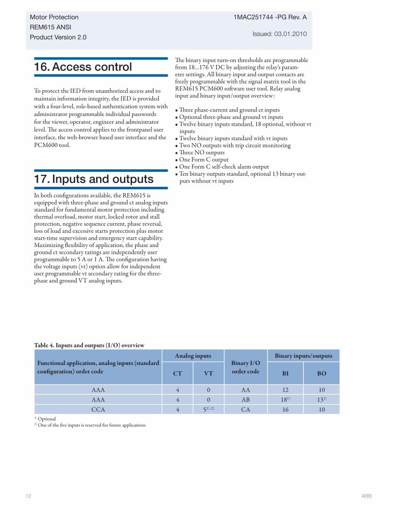
ABB 12
1MAC251744 -PG Rev. A
Issued: 03.01.2010
Motor Protection
REM615 ANSI
Product Version 2.0
16. Access control
To protect the IED from unauthorized access and to maintain information integrity, the IED is provided with a four-level, role-based authentication system with administrator programmable individual passwords for the viewer, operator, engineer and administrator level. Th e access control applies to the frontpanel user interface, the web-browser based user interface and the PCM600 tool.
17. Inputs and outputsIn both confi gurations available, the REM615 is equipped with three-phase and ground ct analog inputs standard for fundamental motor protection including thermal overload, motor start, locked rotor and stall protection, negative sequence current, phase reversal, loss of load and excessive starts protection plus motor start-time supervision and emergency start capability. Maximizing fl exibility of application, the phase and ground ct secondary ratings are independently user programmable to 5 A or 1 A. Th e confi guration having the voltage inputs (vt) option allow for independent user programmable vt secondary rating for the three-phase and ground VT analog inputs.
Th e binary input turn-on thresholds are programmable from 18…176 V DC by adjusting the relay’s param-eter settings. All binary input and output contacts are freely programmable with the signal matrix tool in the REM615 PCM600 soft ware user tool. Relay analog input and binary input/output overview:
• Th ree phase-current and ground ct inputs• Optional three-phase and ground vt inputs• Twelve binary inputs standard, 18 optional, without vt
inputs• Twelve binary inputs standard with vt inputs• Two NO outputs with trip circuit monitoring• Th ree NO outputs• One Form C output• One Form C self-check alarm output• Ten binary outputs standard, optional 13 binary out-
puts without vt inputs
Functional application, analog inputs (standard confi guration) order code
Analog inputsBinary I/O order code
Binary inputs/outputs
CT VT BI BO
AAA 4 0 AA 12 10AAA 4 0 AB 181) 131)
CCA 4 51) ,2) CA 16 101) Optional2) One of the fi ve inputs is reserved for future applications
Table 4. Inputs and outputs (I/O) overview

ABB 13
Motor Protection
REM615 ANSI
Product Version 2.0
1MAC251744 -PG Rev. A
Issued: 03.01.2010
18. Communication
Th e relay supports three diff erent communication protocols: IEC 61850 , DNP3.0 Level 2+ and Modbus®. Operational information and controls are available through these protocols. Unique communication functionality, for example, peer-to-peer communication between relays is available via the IEC 61850 communication protocol.
Th e IEC 61850 communication implementation supports all monitoring and control functions. Additionally, parameter setting and disturbance fi le records can be accessed using the IEC 61850-8-1 protocol. Further, the relay can send and receive binary signals from other relays (peer-to-peer communication) using the IEC61850-8-1 GOOSE profi le, where the highest performance class with a total transmission time of 3 ms is supported. Th e relay can simultaneously report to fi ve diff erent clients - maximum fi ve IEC 61850-8-1 clients, maximum fi ve Modbus clients and maximum one DNP3.0 Level 2+ client with total number not exceeding fi ve.
All communication connectors, except for the front RJ45 connector, are located in the back of the unit on the left most card slot. Th is slot remains in the case when the drawout unit is removed eliminating the need to disconnect communication connections. Th e relay can be connected to an Ethernet-based communications network via a copper RJ45 (100Base TX) or fi beroptic LC (100Base FX) connector or serial network via the RS-485 option that provides one 4-wire or two 2-wire ports.
Modbus over TCP/IP is supported with the Ethernet communications option selected. Besides standard Modbus functionality such as status and control operations, the relay supports retrieval of time-stamped events, uploading of disturbance fi les and storing of the latest fault records. For the Modbus TCP connection, a maximum of , fi ve clients can be connected to the relay simultaneously.
DNP3.0 Level 2+ over TCP/IP is also supported with the Ethernet communications card option. Another serial communications option off ers programmable RS-232 or RS-485 and fi ber-optic (ST) serial ports. Status and control, including breaker trip/close control, operations are supported in the Level 2+ implementation.
Optional serial (RS-232/RS-485) communication interfaces are available that support user programmable protocols of DNP3.0 Level 2+ and Modbus RTU/ASCII. All serial communication card options include an Ethernet communications port and an IRIG-B port for dedicated time synchronization network connections.
Th e relay supports the time synchronization with a time-stamping resolution of +/-1 ms:
Ethernet based:
• SNTP (primary and secondary server support)
Table 5. Supported station communication interfaces and protocols
Interfaces/ProtocolsEthernet Serial100BASE-TX (RJ45)
100BASE-FX (LC) RS-232/RS-485 Fiber-optic (ST)
DNP3.0 Level 2+ over TCP/IP • • - - Modbus over TCP/IP • • - - IEC 61850-8-1 • • - - SNTP • • - - FTP • • - - DNP3.0 Level 2+ serial - - • •Modbus RTU/ASCII - - • • IRIG-B time synchronization - - • •
• = supported

ABB 14
1MAC251744 -PG Rev. A
Issued: 03.01.2010
Motor Protection
REM615 ANSI
Product Version 2.0
19. Technical data
Table 7. Power supply
Description Type 1 Type 2V nominal (Vn) 100, 110, 120, 220, 240 V AC,
60 and 50 Hz48, 60, 110, 125, 220, 250 V DC
24, 30, 48, 60 V DC
Vn variation 38...110% of Vn (38...264 V AC)80...120% of Vn (38.4...300 V DC)
50...120% of Vn (12...72 V DC)
Start-up threshold 19.2 V DC (24 V DC * 80%)
Burden of auxiliary voltage supplyunder quiescent (Pq)/operatingcondition
250 V DC ~8.5 W (nominal) / ~14.1 W (maximum) 240 V AC ~10.2 W (nominal) / ~16.1 W (maximum)
60 V DC ~6.7 W (nomi-nal) / ~12.9 W (maxi-mum)
Ripple in the DC auxiliary voltage Max 12% of the DC value (at frequency of 100 Hz)
Maximum interruption time in theauxiliary DC voltage withoutresetting the relay
110 V DC: 84 ms 110 V AC: 116 ms
48 V DC: 68 ms
Fuse type T4A/250 V
Table 6. DimensionsDescription ValueWidth frame 7.08” (179.8 mm)
case 6.46” (164 mm)Height frame 6.97 (177 mm), 4U
case 6.30” (160 mm)Depth case 7.64” (194 mm)Weight relay 7.72 lbs. (3.5 kg)
draw-out unit 3.97 lbs. (1.8 kg)
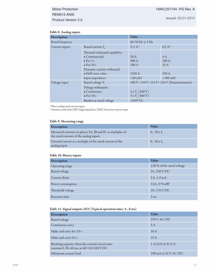
ABB 15
Motor Protection
REM615 ANSI
Product Version 2.0
1MAC251744 -PG Rev. A
Issued: 03.01.2010
Table 8. Analog inputsDescription ValueRated frequency 60/50 Hz ± 5 HzCurrent inputs Rated current, In 5/1 A1) 0.2 A2)
Th ermal withstand capability:• Continuously• For 1 s• For 10 s
20 A500 A100 A
4 A100 A25 A
Dynamic current withstand:• Half-wave value 1250 A 250 AInput impedance <20 mΩ <100 mΩ
Voltage input Rated voltage Vn 100 V/ 110 V/ 115 V/ 120 V (Parametrization)Voltage withstand:• Continuous• For 10 s
2 x Vn (240 V)3 x Vn (360 V)
Burden at rated voltage <0.05 VA1) Phase and ground current inputs2) Sensitive earth fault (SEF)/high impedance (HIZ) detection current input
Table 9. Measuring range
Description Value
Measured currents on phases IA, IB and IC as multiples ofthe rated currents of the analog inputs
0... 50 x In
Ground current as a multiple of the rated current of theanalog input
0... 50 x In
Table 10. Binary inputs
Description Value
Operating range ±20 % of the rated voltage
Rated voltage 24...250 V DC
Current drain 1.6...1.9 mA
Power consumption 31.0...570 mW
Th reshold voltage 18...176 V DC
Reaction time 3 ms
Table 11. Signal outputs (SO) [Typical operation time: 5...8 ms]
Description Value
Rated voltage 250 V AC/DC
Continuous carry 5 A
Make and carry for 3.0 s 10 A
Make and carry 0.5 s 15 A
Breaking capacity when the control-circuit timeconstant L/R<40 ms, at 48/110/220 V DC
1 A/0.25 A/0.15 A
Minimum contact load 100 mA at 24 V AC/DC
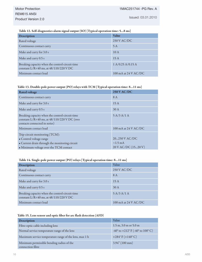
ABB 16
1MAC251744 -PG Rev. A
Issued: 03.01.2010
Motor Protection
REM615 ANSI
Product Version 2.0
Table 12. Self-diagnostics alarm signal output (SO) [Typical operation time: 5...8 ms]Description Value
Rated voltage 250 V AC/DC
Continuous contact carry 5 A
Make and carry for 3.0 s 10 A
Make and carry 0.5 s 15 A
Breaking capacity when the control-circuit timeconstant L/R<40 ms, at 48/110/220 V DC
1 A/0.25 A/0.15 A
Minimum contact load 100 mA at 24 V AC/DC
Table 13. Double-pole power output (PO) relays with TCM [Typical operation time: 8...11 ms]
Rated voltage 250 V AC/DC
Continuous contact carry 8 A
Make and carry for 3.0 s 15 A
Make and carry 0.5 s 30 A
Breaking capacity when the control-circuit timeconstant L/R<40 ms, at 48/110/220 V DC (twocontacts connected in series)
5 A/3 A/1 A
Minimum contact load 100 mA at 24 V AC/DC
Trip-circuit monitoring (TCM):• Control voltage range• Current drain through the monitoring circuit• Minimum voltage over the TCM contact
20...250 V AC/DC~1.5 mA20 V AC/DC (15...20 V)
Table 14. Single-pole power output (PO) relays [Typical operation time: 8...11 ms]Description Value
Rated voltage 250 V AC/DC
Continuous contact carry 8 A
Make and carry for 3.0 s 15 A
Make and carry 0.5 s 30 A
Breaking capacity when the control-circuit timeconstant L/R<40 ms, at 48/110/220 V DC
5 A/3 A/1 A
Minimum contact load 100 mA at 24 V AC/DC
Table 15. Lens sensor and optic fi ber for arc fl ash detection (AFD)
Description Value
Fibre-optic cable including lens 1.5 m, 3.0 m or 5.0 m
Normal service temperature range of the lens -40° to +212° F (-40° to 100° C)
Maximum service temperature range of the lens, max 1 h +284° F (+140° C)
Minimum permissible bending radius of theconnection fi bre
3.94” (100 mm)

ABB 17
Motor Protection
REM615 ANSI
Product Version 2.0
1MAC251744 -PG Rev. A
Issued: 03.01.2010
Table 16. Degree of protection of fl ush-mounted relay
Description ValueFront side IP 54
Back side, connection terminals IP 20
Table 17. Environmental conditions
Description Value
Continuous operating temperature range -25 C to +55° C
Short-term operating temperature range -40 C to +85° C (<16 h) 1) 2)
Relative humidity <93%, non-condensing
Atmospheric pressure 12.47 - 15.37 psi (86 - 106 kPa)
Altitude up to 6561 ft . (2000 m)
Transport and storage temperature range -40...+85ºC1) Degradation in MTBF and LHMI performance outside continuous operating temperature range. 2) For relays with an LC communications interface, the maximum operating temperature is +70° C
Table 18. Environmental testsDescription Type test value Reference
Dry heat test (humidity <50%)
• 96 h at +55ºC• 16 h at +85ºC1)
IEC 60068-2-2
Dry cold test • 96 h at -25ºC• 16 h at -40ºC
IEC 60068-2-1
Damp heat test, cyclic • 6 cycles (12 h + 12 h) at +25°C…+55°C, humidity >93% IEC 60068-2-30
Storage test • 96 h at -40ºC• 96 h at +85ºC
IEC 60068-2-48
1) For IEDs with an LC communication interface the maximum operating temperature is +70oC

ABB 18
1MAC251744 -PG Rev. A
Issued: 03.01.2010
Motor Protection
REM615 ANSI
Product Version 2.0
Table 19. Electromagnetic compatibility tests
Th e EMC immunity test level meets the requirements listed below:Description Type test value Reference1 MHz burst disturbance test, class III:
• Common mode• Diff erential mode
2.5 kV1.0 kV
According to IEC 61000-4-18 and IEC 60255-22-1, level 3
Electrostatic discharge test
• Contact discharge• Air discharge
6 kV8 kV
According to IEC 61000-4-2,IEC 60255-22-2, level 3
Radio frequency interference tests:• Conducted, common mode
• Radiated, amplitude-modulated
• Radiated, pulse-modulated
10 V (emf ), f = 150 kHz...80 MHz
10 V/m (rms), f=80...1000 MHz and f=1.4...2.7 GHz
10 V/m, f=900 MHz
According to IEC 61000-4-6 and IEC 60255-22-6, level 3
According to IEC 61000-4-3 and IEC 60255-22-3, level 3
According to the ENV 50204 and IEC 60255-22-3, level 3
Fast transient disturbance tests:
• Signal outputs, binary inputs, IRF• Other ports
2 kV4 kV
According to IEC 61000-4-4 and IEC 60255-22-4, class B
Surge immunity test:
• Binary inputs
• Communication• Other ports
2 kV, line-to-earth1kV, line-to-line1 kV, line-to-earth4 kV, line-to-earth2 kV, line-to-line
According to IEC 61000-4-5 and IEC 60255-22-5, level 4/3
Power frequency (50 Hz) magnetic fi eld:
• Continuous 300 A/m
According to IEC 61000-4-8, level 5
Power frequency immunity test:
• Common mode• Diff erential mode
300 V rms150 V rms
According to IEC 60255-22-7, class A
Voltage dips and short interruptions 30%/10 ms60%/100 ms60%/1000 ms>95%/5000 ms
According to IEC 61000-4-11

ABB 19
Motor Protection
REM615 ANSI
Product Version 2.0
1MAC251744 -PG Rev. A
Issued: 03.01.2010
Table 20. Insulation tests
Description ValueDielectric tests: According to IEC 60255-5• Test voltage 2 kV, 50 Hz, 1 min
500 V, 50 Hz, 1min, communication
Impulse voltage test: According to IEC 60255-5• Test voltage 5 kV, unipolar impulses, waveform
1.2/50 μs, source energy 0.5 J 1 kV, unipolar impulses, waveform 1.2/50 μs, source energy 0.5 J, com-munication
Insulation resistance measurements According to IEC 60255-5• Isolation resistance >100 MΩ, 500 V DCProtective bonding resistance• Resistance
According to IEC 60255-27<0.1 Ω (60 s)
Table 21. Mechanical tests
Description ValueVibration tests (sinusoidal) According to IEC 60255-21-1,
class 2Shock and bump test According to IEC 60255-21-2,
class 2
Table 19. Electromagnetic compatibility tests (continued)
Th e EMC immunity test level meets the requirements listed below:Description ValueElectromagnetic emission tests:
• Conducted, RF emission (mains terminal)0.15...0.50 MHz
0.5...30 MHz
• Radiated RF emission0...230 MHz
230...1000 MHz
According to the EN 55011, class A and IEC60255-25
< 79 dB(μV) quasi peak< 66 dB(μV) average< 73 dB(μV) quasi peak< 60 dB(μV) average
< 40 dB(μV/m) quasi peak, measured at 10 m distance< 47 dB(μV/m) quasi peak, measured at 10 m distance
Table 22. EMC Compliance Description Reference
EMC directive 2004/108/EC
Standard EN 50263 (2000)EN 60255-26 (2007)
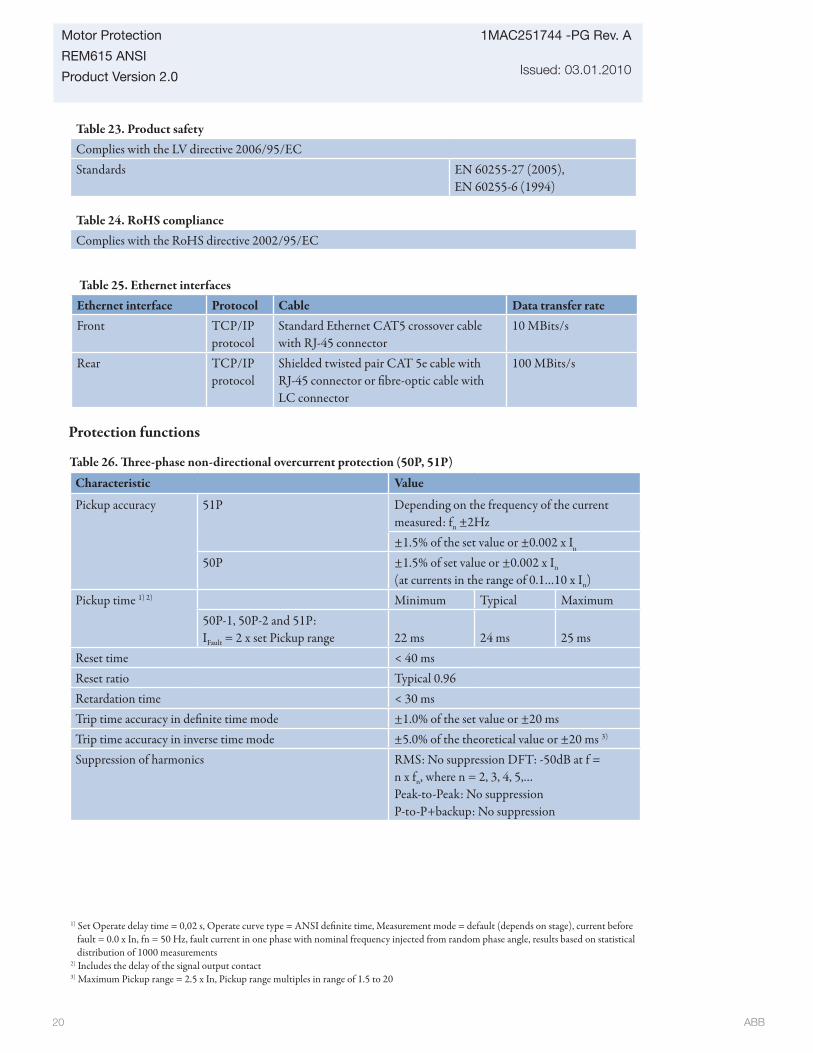
ABB 20
1MAC251744 -PG Rev. A
Issued: 03.01.2010
Motor Protection
REM615 ANSI
Product Version 2.0
Table 23. Product safetyComplies with the LV directive 2006/95/ECStandards EN 60255-27 (2005),
EN 60255-6 (1994)
Table 25. Ethernet interfacesEthernet interface Protocol Cable Data transfer rateFront TCP/IP
protocolStandard Ethernet CAT5 crossover cable with RJ-45 connector
10 MBits/s
Rear TCP/IP protocol
Shielded twisted pair CAT 5e cable with RJ-45 connector or fi bre-optic cable with LC connector
100 MBits/s
Table 24. RoHS complianceComplies with the RoHS directive 2002/95/EC
Protection functions
Table 26. Th ree-phase non-directional overcurrent protection (50P, 51P)
Characteristic Value
Pickup accuracy 51P Depending on the frequency of the current measured: fn ±2Hz±1.5% of the set value or ±0.002 x In
50P ±1.5% of set value or ±0.002 x In
(at currents in the range of 0.1…10 x In)Pickup time 1) 2) Minimum Typical Maximum
50P-1, 50P-2 and 51P:IFault = 2 x set Pickup range 22 ms 24 ms 25 ms
Reset time < 40 msReset ratio Typical 0.96Retardation time < 30 msTrip time accuracy in defi nite time mode ±1.0% of the set value or ±20 msTrip time accuracy in inverse time mode ±5.0% of the theoretical value or ±20 ms 3)
Suppression of harmonics RMS: No suppression DFT: -50dB at f = n x fn, where n = 2, 3, 4, 5,…Peak-to-Peak: No suppressionP-to-P+backup: No suppression
1) Set Operate delay time = 0,02 s, Operate curve type = ANSI defi nite time, Measurement mode = default (depends on stage), current before fault = 0.0 x In, fn = 50 Hz, fault current in one phase with nominal frequency injected from random phase angle, results based on statistical distribution of 1000 measurements
2) Includes the delay of the signal output contact3) Maximum Pickup range = 2.5 x In, Pickup range multiples in range of 1.5 to 20
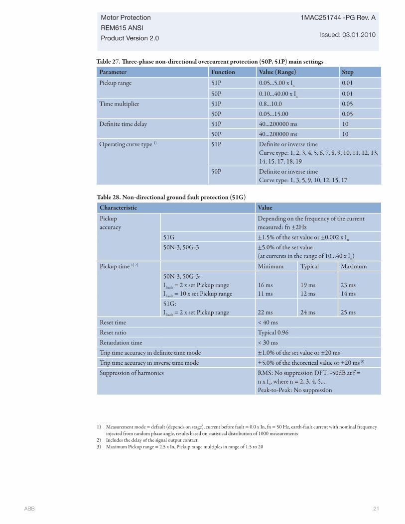
ABB 21
Motor Protection
REM615 ANSI
Product Version 2.0
1MAC251744 -PG Rev. A
Issued: 03.01.2010
Table 27. Th ree-phase non-directional overcurrent protection (50P, 51P) main settings
Parameter Function Value (Range) Step
Pickup range 51P 0.05...5.00 x In 0.01
50P 0.10...40.00 x In 0.01Time multiplier 51P 0.8...10.0 0.05
50P 0.05...15.00 0.05Defi nite time delay 51P 40...200000 ms 10
50P 40...200000 ms 10Operating curve type 1) 51P Defi nite or inverse time
Curve type: 1, 2, 3, 4, 5, 6, 7, 8, 9, 10, 11, 12, 13, 14, 15, 17, 18, 19
50P Defi nite or inverse timeCurve type: 1, 3, 5, 9, 10, 12, 15, 17
Table 28. Non-directional ground fault protection (51G)
Characteristic Value
Pickup accuracy
Depending on the frequency of the current measured: fn ±2Hz
51G ±1.5% of the set value or ±0.002 x In
50N-3, 50G-3 ±5.0% of the set value(at currents in the range of 10…40 x In)
Pickup time 1) 2) Minimum Typical Maximum50N-3, 50G-3:IFault = 2 x set Pickup rangeIFault = 10 x set Pickup range
16 ms11 ms
19 ms12 ms
23 ms14 ms
51G:IFault = 2 x set Pickup range 22 ms 24 ms 25 ms
Reset time < 40 msReset ratio Typical 0.96Retardation time < 30 msTrip time accuracy in defi nite time mode ±1.0% of the set value or ±20 msTrip time accuracy in inverse time mode ±5.0% of the theoretical value or ±20 ms 3)
Suppression of harmonics RMS: No suppression DFT: -50dB at f = n x fn, where n = 2, 3, 4, 5,…Peak-to-Peak: No suppression
1) Measurement mode = default (depends on stage), current before fault = 0.0 x In, fn = 50 Hz, earth-fault current with nominal frequency injected from random phase angle, results based on statistical distribution of 1000 measurements
2) Includes the delay of the signal output contact3) Maximum Pickup range = 2.5 x In, Pickup range multiples in range of 1.5 to 20

ABB 22
1MAC251744 -PG Rev. A
Issued: 03.01.2010
Motor Protection
REM615 ANSI
Product Version 2.0
Table 30.Directional ground fault protection (67/51N)Characteristic Value
Pickup accuracy
Depending on the frequency of the current meas-ured: fn ±2Hz
67/51N Current: ±1.5% of the set value or ±0.002 x In
Voltage: ±1.5% of the set value or ±0.002 x Un
Phase angle: ±2°
Pickup time 1) 2) Minimum Typical Maximum67/51N:IFault = 2 x set Pickup range
61 ms 64 ms 66 msReset time < 40 msReset ratio Typical 0.96Retardation time < 30 msTrip time accuracy in defi nite time mode ±1.0% of the set value or ±20 msTrip time accuracy in inverse time mode ±5.0% of the theoretical value or ±20 ms 3)
Suppression of harmonics RMS: No suppression DFT: -50dB at f = n x fn, where n = 2, 3, 4, 5,…Peak-to-Peak: No suppression
1) Set Defi nite time delay = 0,06 s, Inverse-time (IDMT) and defi nite-time (DT) curves = IEC defi nite time, Measurement mode = default (depends on stage), current before fault = 0.0 x In, fn = 50 Hz, earth-fault current with nominal frequency injected from random phase angle, results based on statistical distribution of 1000 measurements
2) Includes the delay of the signal output contact3) Maximum Pickup range = 2.5 x In, Pickup range multiples in range of 1.5 to 20
Table 29. Non-directional ground fault protection (51G) main settings
Parameter Function Value (Range) StepPickup range 51G 0.05...5.00 x In 0.01
Time multiplier 51G 0.05...15.00 0.05Defi nite time delay 51G 40...200000 ms 10
Operating curve type 1) 51G Defi nite or inverse timeCurve type: 1, 2, 3, 4, 5, 6, 7, 8, 9, 10, 11, 12, 13, 14, 15, 17, 18, 19
1) For further reference please refer to the Operating characteristics table at the end of the Technical data chapter
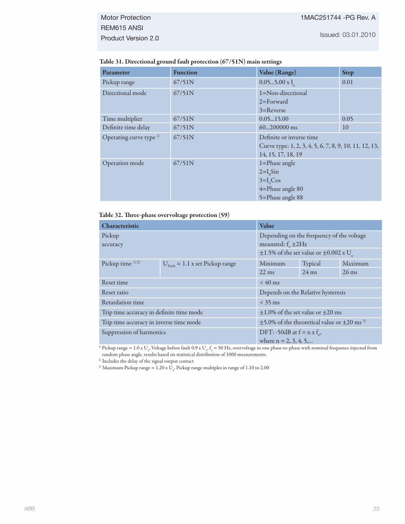
ABB 23
Motor Protection
REM615 ANSI
Product Version 2.0
1MAC251744 -PG Rev. A
Issued: 03.01.2010
Table 31. Directional ground fault protection (67/51N) main settings
Parameter Function Value (Range) StepPickup range 67/51N 0.05...5.00 x In 0.01
Directional mode 67/51N 1=Non-directional2=Forward3=Reverse
Time multiplier 67/51N 0.05...15.00 0.05Defi nite time delay 67/51N 60...200000 ms 10Operating curve type 1) 67/51N Defi nite or inverse time
Curve type: 1, 2, 3, 4, 5, 6, 7, 8, 9, 10, 11, 12, 13, 14, 15, 17, 18, 19
Operation mode 67/51N 1=Phase angle2=I0Sin3=I0Cos4=Phase angle 805=Phase angle 88
Table 32. Th ree-phase overvoltage protection (59)
Characteristic ValuePickup accuracy
Depending on the frequency of the voltage measured: fn ±2Hz±1.5% of the set value or ±0.002 x Un
Pickup time 1) 2) UFault = 1.1 x set Pickup range Minimum Typical Maximum22 ms 24 ms 26 ms
Reset time < 40 msReset ratio Depends on the Relative hysteresisRetardation time < 35 msTrip time accuracy in defi nite time mode ±1.0% of the set value or ±20 msTrip time accuracy in inverse time mode ±5.0% of the theoretical value or ±20 ms 3)
Suppression of harmonics DFT: -50dB at f = n x fn, where n = 2, 3, 4, 5,…
1) Pickup range = 1.0 x Un, Voltage before fault 0.9 x Un, fn = 50 Hz, overvoltage in one phase-to-phase with nominal frequence injected from random phase angle, results based on statistical distribution of 1000 measurements.
2) Includes the delay of the signal output contact3) Maximum Pickup range = 1.20 x Un, Pickup range multiples in range of 1.10 to 2.00
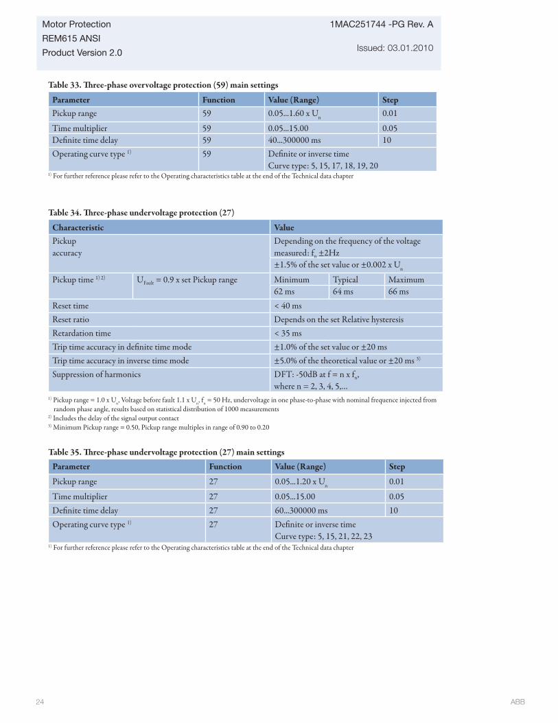
ABB 24
1MAC251744 -PG Rev. A
Issued: 03.01.2010
Motor Protection
REM615 ANSI
Product Version 2.0
Table 33. Th ree-phase overvoltage protection (59) main settings
Parameter Function Value (Range) StepPickup range 59 0.05...1.60 x Un 0.01
Time multiplier 59 0.05...15.00 0.05Defi nite time delay 59 40...300000 ms 10Operating curve type 1) 59 Defi nite or inverse time
Curve type: 5, 15, 17, 18, 19, 201) For further reference please refer to the Operating characteristics table at the end of the Technical data chapter
Table 34. Th ree-phase undervoltage protection (27)
Characteristic ValuePickup accuracy
Depending on the frequency of the voltage measured: fn ±2Hz±1.5% of the set value or ±0.002 x Un
Pickup time 1) 2) UFault = 0.9 x set Pickup range Minimum Typical Maximum62 ms 64 ms 66 ms
Reset time < 40 msReset ratio Depends on the set Relative hysteresisRetardation time < 35 msTrip time accuracy in defi nite time mode ±1.0% of the set value or ±20 msTrip time accuracy in inverse time mode ±5.0% of the theoretical value or ±20 ms 3)
Suppression of harmonics DFT: -50dB at f = n x fn, where n = 2, 3, 4, 5,…
Table 35. Th ree-phase undervoltage protection (27) main settings
Parameter Function Value (Range) Step
Pickup range 27 0.05...1.20 x Un 0.01
Time multiplier 27 0.05...15.00 0.05Defi nite time delay 27 60...300000 ms 10Operating curve type 1) 27 Defi nite or inverse time
Curve type: 5, 15, 21, 22, 23
1) Pickup range = 1.0 x Un, Voltage before fault 1.1 x Un, fn = 50 Hz, undervoltage in one phase-to-phase with nominal frequence injected from random phase angle, results based on statistical distribution of 1000 measurements
2) Includes the delay of the signal output contact3) Minimum Pickup range = 0.50, Pickup range multiples in range of 0.90 to 0.20
1) For further reference please refer to the Operating characteristics table at the end of the Technical data chapter

ABB 25
Motor Protection
REM615 ANSI
Product Version 2.0
1MAC251744 -PG Rev. A
Issued: 03.01.2010
Table 36. Positive sequence undervoltage protection (27PS)
Characteristic Value
Pickup accuracy
Depending on the frequency of the voltage measured: fn ±2Hz±1.5% of the set value or ±0.002 x Un
Pickup time 1) 2) UFault = 0.99 x set Pickup range Minimum Typical Maximum51 ms 53 ms 54 ms
UFault = 0.9 x set Pickup range 43 ms 45 ms 46 msReset time < 40 msReset ratio Depends on the set Relative hysteresisRetardation time < 35 msTrip time accuracy in defi nite time mode ±1.0% of the set value or ±20 msSuppression of harmonics DFT: -50dB at f = n x fn,
where n = 2, 3, 4, 5,…1) Pickup range = 1.0 x Un, Positive sequence voltage before fault 1.1 x Un, fn = 50 Hz, positive sequence undervoltage with nominal frequence
injected from random phase angle, results based on statistical distribution of 1000 measurements2) Includes the delay of the signal output contact
Table 37. Positive sequence undervoltage protection (27PS) main settings
Parameter Function Value (Range) Step
Pickup range 27PS 0.010...1.200 x Un 0.001
Defi nite time delay 27PS 40...120000 ms 10Voltage block value 27PS 0.01...1.0 x Un 0.01
Table 38. Negative sequence overvoltage protection (47)
Characteristic Value
Pickup accuracy
Depending on the frequency of the voltage measured: fn ±2Hz±1.5% of the set value or ±0.002 x Un
Pickup time 1) 2) Minimum Typical MaximumUFault = 1.1 x set Pickup range 33 ms 35 ms 37 msUFault = 2.0 x set Pickup range 24 ms 26 ms 28 ms
Reset time < 40 msReset ratio Typical 0.96Retardation time < 35 msTrip time accuracy in defi nite time mode ±1.0% of the set value or ±20 msSuppression of harmonics DFT: -50dB at f = n x fn,
where n = 2, 3, 4, 5,…1) Negative sequence voltage before fault 0.0 x Un, fn = 50 Hz, negative sequence overvoltage with nominal frequence injected from random
phase angle, results based on statistical distribution of 1000 measurements2) Includes the delay of the signal output contact

ABB 26
1MAC251744 -PG Rev. A
Issued: 03.01.2010
Motor Protection
REM615 ANSI
Product Version 2.0
Table 39. Negative sequence overvoltage protection (47) main settings
Parameter Function Value (Range) Step
Pickup range 47 0.010...1.000 x Un 0.001
Defi nite time delay 47 40...120000 ms 1
Table 42. Negative phase-sequence current protection (46)Characteristic ValuePickup Accuracy Depending on the frequency of the
current measured: fn = ±2Hz±1.5% of the set value or ±0.002 x In
Pickup time 1) 2) Minimum Typical MaximumIFault = 2 x set Pickup rangeIFault = 10 x set Pickup range
22 ms14 ms
24 ms16 ms
25 ms17 ms
Reset time < 40 msReset ratio Typical 0.96Retardation time < 35 msTrip time accuracy in defi nite time mode ±1.0% of the set value or ±20 msTrip time accuracy in inverse time mode ±5.0% of the theoretical value or ±20 ms 3)
Suppression of harmonics DFT: -50dB at f = n x fn, where n = 2, 3, 4, 5,…
1) Negative sequence current before fault = 0.0, fn = 50 Hz, results based on statistical distribution of 1000 measurements2) Includes the delay of the signal output contact3) Maximum Pickup range = 2.5 x In, Pickup range multiples in range of 1.5 to 20
Table 40. Ground overvoltage protection (59G)
Characteristic ValuePickup accuracy
Depending on the frequency of the voltage measured: fn ±2Hz±1.5% of the set value or ±0.002 x Un
Pickup time 1) 2) Minimum Typical MaximumUFault = 1.1 x set Pickup range 29 ms 31 ms 32 ms
Reset time < 40 msReset ratio Typical 0.96Retardation time < 35 msTrip time accuracy in defi nite time mode ±1.0% of the set value or ±20 msSuppression of harmonics DFT: -50dB at f = n x fn,
where n = 2, 3, 4, 5,…1) Residual voltage before fault 0.0 x Un, fn = 50 Hz, residual voltage with nominal frequency injected from random phase angle, results based
on statistical distribution of 1000 measurements2) Includes the delay of the signal output contact
Table 41. Ground overvoltage protection (59G) main settings
Parameter Function Value (Range) StepPickup range 59G 0.010...1.000 x Un 0.001
Defi nite time delay 59G 40...300000 ms 1

ABB 27
Motor Protection
REM615 ANSI
Product Version 2.0
1MAC251744 -PG Rev. A
Issued: 03.01.2010
Table 44. Loss of load supervision (37)Characteristic ValueOperation Accuracy Depending on the frequency of the current
measured: fn ±2Hz±1.5% of the set value or ±0.002 x In
Start time Typical 300 msReset time < 40 msReset ratio Typical 0.96Retardation time < 35 msOperate time accuracy in defi nite time mode ±1.0% of the set value or ±20 ms
Table 46. Motor load jam protection (51LR)Characteristic ValueOperation Accuracy Depending on the frequency of the current
measured: fn ±2Hz±1.5% of the set value or ±0.002 x In
Reset time < 40 msReset ratio Typical 0.96Retardation time < 35 msOperate time accuracy in defi nite time mode ±1.0% of the set value or ±20 ms
Table 45. Loss of load supervision (37) main settings
Parameter Function Value (Range) StepStart value high 37 0.01...1.00 x In 0.01
Start value low 37 0.01...0.50 x In 0.01Operate delay time 37 40...600000 ms 10Operation 37 Off
On-
Table 47. Motor load jam protection (51LR) main settings
Parameter Function Value (Range) StepOperation 51LR Off
On-
Start value 51LR 0.01...10.00 x In 0.01Operate delay time 51LR 100...120000 ms 10
Table 43. Negative phase-sequence current protection (46) main settings
Parameter Function Value (Range) StepPickup range 46 0.01...5.00 x In 0.01
Time multiplier 46 0.05...15.00 0.05Defi nite time delay 46 40...200000 ms 10Operating curve type 1) 46 Defi nite or inverse time
Curve type: 1, 2, 3, 4, 5, 6, 7, 8, 9, 10, 11, 12, 13, 14, 15, 17, 18, 19
1) For further reference please refer to the Operating characteristics table at the end of the Technical data chapter
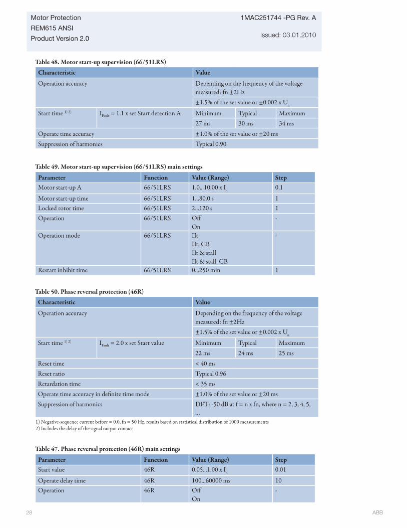
ABB 28
1MAC251744 -PG Rev. A
Issued: 03.01.2010
Motor Protection
REM615 ANSI
Product Version 2.0
Table 47. Phase reversal protection (46R) main settings
Parameter Function Value (Range) StepStart value 46R 0.05...1.00 x In 0.01
Operate delay time 46R 100...60000 ms 10Operation 46R Off
On-
Table 48. Motor start-up supervision (66/51LRS)
Characteristic Value
Operation accuracy Depending on the frequency of the voltage measured: fn ±2Hz±1.5% of the set value or ±0.002 x Un
Start time 1) 2) IFault = 1.1 x set Start detection A Minimum Typical Maximum27 ms 30 ms 34 ms
Operate time accuracy ±1.0% of the set value or ±20 msSuppression of harmonics Typical 0.90
Table 49. Motor start-up supervision (66/51LRS) main settings
Parameter Function Value (Range) StepMotor start-up A 66/51LRS 1.0...10.00 x In 0.1
Motor start-up time 66/51LRS 1...80.0 s 1Locked rotor time 66/51LRS 2...120 s 1Operation 66/51LRS Off
On-
Operation mode 66/51LRS IItIIt, CBIIt & stallIIt & stall, CB
-
Restart inhibit time 66/51LRS 0...250 min 1
Table 50. Phase reversal protection (46R)
Characteristic Value
Operation accuracy Depending on the frequency of the voltage measured: fn ±2Hz±1.5% of the set value or ±0.002 x Un
Start time 1) 2) IFault = 2.0 x set Start value Minimum Typical Maximum22 ms 24 ms 25 ms
Reset time < 40 msReset ratio Typical 0.96Retardation time < 35 msOperate time accuracy in defi nite time mode ±1.0% of the set value or ±20 msSuppression of harmonics DFT: -50 dB at f = n x fn, where n = 2, 3, 4, 5,
…1) Negative-sequence current before = 0.0, fn = 50 Hz, results based on statistical distribution of 1000 measurements2) Includes the delay of the signal output contact

ABB 29
Motor Protection
REM615 ANSI
Product Version 2.0
1MAC251744 -PG Rev. A
Issued: 03.01.2010
Table 52. Th ermal overload protection for motors (49M) main settings
Parameter Function Value (Range) StepEnv temperaturemode
49M FLC OnlyUse RTDSet Amb Temp
-
Env temperature set 49M -20.0...70.0 °C 0.1Alarm thermal value 49M 50.0...100.0 % 0.1Restart thermal value 49M 20.0...80.0 % 0.1Overload factor 49M 1.00...1.20 0.01Weighting factor p 49M 20.0...100.0 0.1Time constant normal 49M 80...4000 s 1Time constant start 49M 80...4000 s 1Operation 49M Off
On-
Table 51. Th ree-phase thermal overload protection for motors (49M)
Characteristic Value
Operation accuracy Depending on the frequency of the voltage measured: fn ±2HzCurrent measurement: ±1.5% of the set value or ±0.002 x In (at currents in the range of 0.01...4.00 x In)
Operate time accuracy ±2.0% of the theoretical value or ±0.50 s1) Overload current > 1.2 x Operate level temperature
Table 54. Circuit breaker failure protection (50BF/50NBF) main settings
Parameter Function Value (Range) StepCurrent value(Operating phase current)
50BF/50NBF 0.05...1.00 x In 0.05
Current value Res(Operating residual current)
50BF/50NBF 0.05...1.00 x In 0.05
CB failure mode(Operating mode of function)
50BF/50NBF 1=Current2=Breaker status3=Both
CB fail trip mode 50BF/50NBF 1=Off 2=Without check3=Current check
Retrip time 50BF/50NBF 0...60000 ms 10CB failure delay 50BF/50NBF 0...60000 ms 10CB fault delay 50BF/50NBF 0...60000 ms 10
Table 53. Circuit breaker failure protection (50BF/50NBF)Characteristic ValuePickup Accuracy Depending on the frequency of the current
measured: fn ±2Hz±1.5% of the set value or ±0.002 x In
Trip time accuracy ±1.0% of the set value or ±20 ms

ABB 30
1MAC251744 -PG Rev. A
Issued: 03.01.2010
Motor Protection
REM615 ANSI
Product Version 2.0
Measurement functions
Table 58. Th ree-phase current measurements (IA, IB, IC)
Characteristic Value
Pickup accuracy
Depending on the frequency of the current measured: fn ±2Hz
±0.5% or ±0.002 x In(at currents in the range of 0.01...4.00 x In)
Suppression of har-monics
DFT: -50dB at f = n x fn, where n = 2, 3, 4, 5,…RMS: No suppression
Table 59. Current sequence components (I1, I2, I0)
Characteristic Value
Pickup accuracy
Depending on the frequency of the current measured: f/fn = ±2Hz
±1.0% or ±0.002 x Inat currents in the range of 0.01...4.00 x In
Suppression of har-monics
DFT: -50dB at f = n x fn, where n = 2, 3, 4, 5,…
Table 57. Emergency startup (62EST) main settings
Parameter Function Value (Range) Step
Operation 62EST Off On
-
Motor stand still A 62EST 0.05...0.20 x In 0.01
Control functions
Table 55. Arc protection (AFD)
Characteristic ValuePickup Accuracy ±3% of the set value or ±0.01 x In
Trip time Minimum Typical MaximumOperation mode = “Light+current” 1) 2) 9 ms 12 ms 15 msOperation mode = “Light only” 2) 9 ms 10 ms 12 ms
Reset time < 40 msReset ratio Typical 0.96
1) Phase Pickup range = 1.0 x In, current before fault = 2.0 x set Phase Pickup range, fn = 50Hz, fault with nominal frequency, results based on statistical distribution 200 measurements
2) Includes the delay of the heavy-duty output contact
Table 56. Arc protection (AFD) main settings
Parameter Function Value (Range) Step
Phase Pickup range(Operating phase current)
AFD 0.50...40.00 x In 0.01
Ground Pickup range(Operating residual current)
AFD 0.05...8.00 x In 0.01
Operation mode AFD 1=Light+current2=Light only3=BI controlled
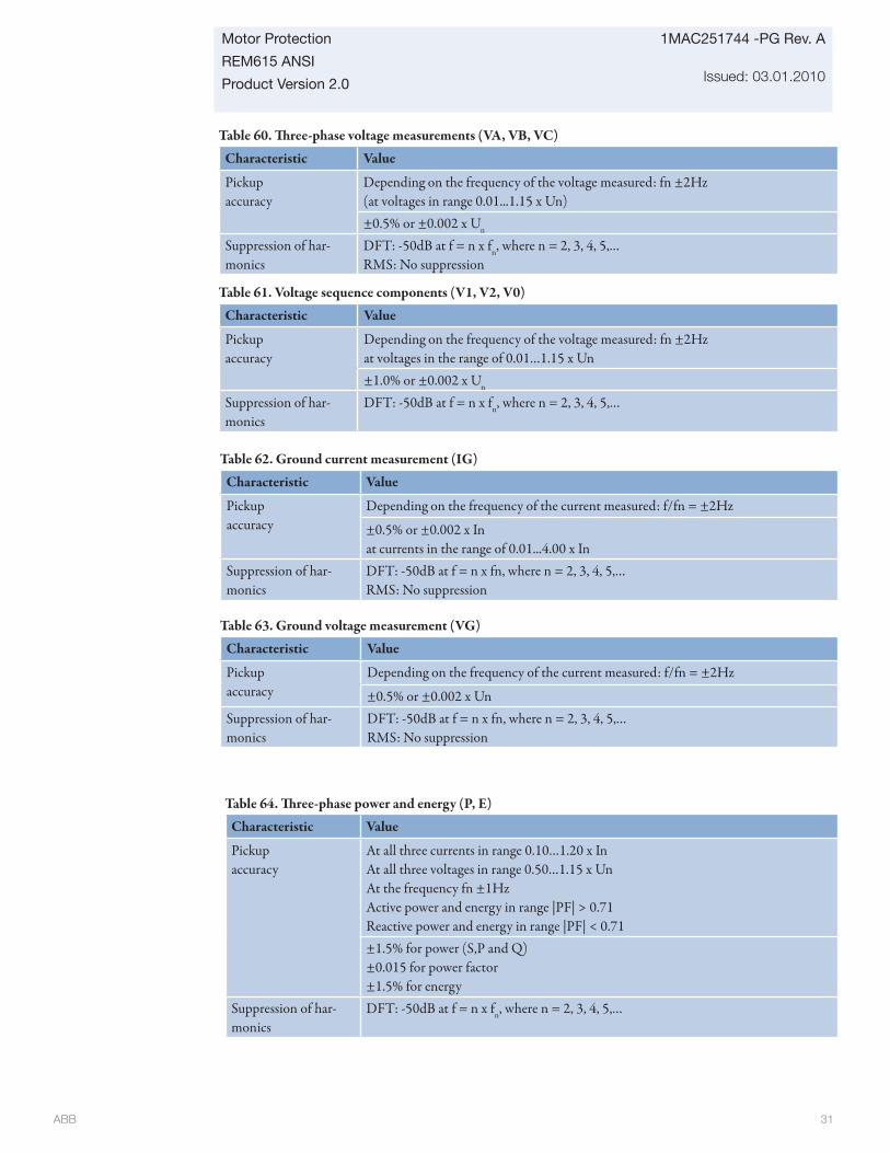
ABB 31
Motor Protection
REM615 ANSI
Product Version 2.0
1MAC251744 -PG Rev. A
Issued: 03.01.2010
Table 60. Th ree-phase voltage measurements (VA, VB, VC)
Characteristic Value
Pickup accuracy
Depending on the frequency of the voltage measured: fn ±2Hz(at voltages in range 0.01...1.15 x Un) ±0.5% or ±0.002 x Un
Suppression of har-monics
DFT: -50dB at f = n x fn, where n = 2, 3, 4, 5,…RMS: No suppression
Table 61. Voltage sequence components (V1, V2, V0)
Characteristic Value
Pickup accuracy
Depending on the frequency of the voltage measured: fn ±2Hzat voltages in the range of 0.01…1.15 x Un±1.0% or ±0.002 x Un
Suppression of har-monics
DFT: -50dB at f = n x fn, where n = 2, 3, 4, 5,…
Table 64. Th ree-phase power and energy (P, E)
Characteristic Value
Pickupaccuracy
At all three currents in range 0.10…1.20 x InAt all three voltages in range 0.50…1.15 x Un At the frequency fn ±1HzActive power and energy in range |PF| > 0.71Reactive power and energy in range |PF| < 0.71±1.5% for power (S,P and Q)±0.015 for power factor±1.5% for energy
Suppression of har-monics
DFT: -50dB at f = n x fn, where n = 2, 3, 4, 5,…
Table 62. Ground current measurement (IG)
Characteristic Value
Pickup accuracy
Depending on the frequency of the current measured: f/fn = ±2Hz
±0.5% or ±0.002 x Inat currents in the range of 0.01...4.00 x In
Suppression of har-monics
DFT: -50dB at f = n x fn, where n = 2, 3, 4, 5,…RMS: No suppression
Table 63. Ground voltage measurement (VG)
Characteristic Value
Pickup accuracy
Depending on the frequency of the current measured: f/fn = ±2Hz
±0.5% or ±0.002 x UnSuppression of har-monics
DFT: -50dB at f = n x fn, where n = 2, 3, 4, 5,…RMS: No suppression
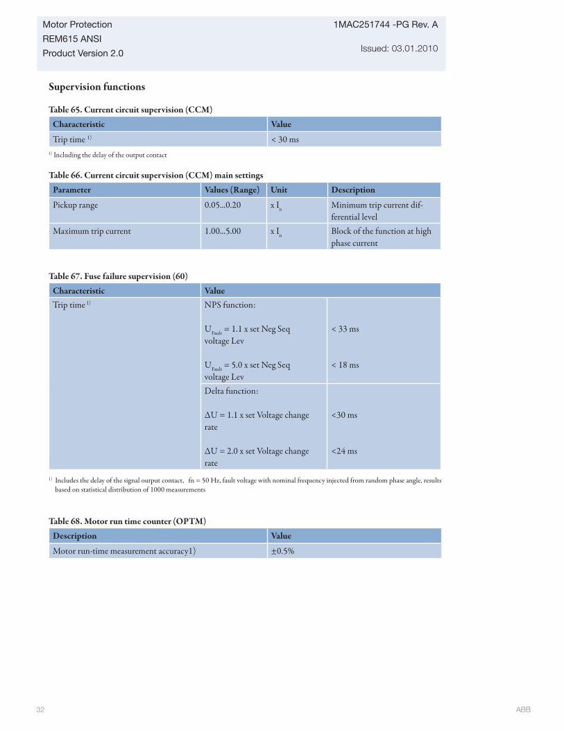
ABB 32
1MAC251744 -PG Rev. A
Issued: 03.01.2010
Motor Protection
REM615 ANSI
Product Version 2.0
Table 68. Motor run time counter (OPTM)
Description Value
Motor run-time measurement accuracy1) ±0.5%
Supervision functions
Table 65. Current circuit supervision (CCM)
Characteristic Value
Trip time 1) < 30 ms1) Including the delay of the output contact
Table 66. Current circuit supervision (CCM) main settings
Parameter Values (Range) Unit Description
Pickup range 0.05...0.20 x In Minimum trip current dif-ferential level
Maximum trip current 1.00...5.00 x In Block of the function at high phase current
Table 67. Fuse failure supervision (60)
Characteristic ValueTrip time 1) NPS function:
UFault = 1.1 x set Neg Seq voltage Lev
UFault = 5.0 x set Neg Seq voltage Lev
< 33 ms
< 18 ms
Delta function:
ΔU = 1.1 x set Voltage change rate
ΔU = 2.0 x set Voltage change rate
<30 ms
<24 ms
1) Includes the delay of the signal output contact, fn = 50 Hz, fault voltage with nominal frequency injected from random phase angle, results based on statistical distribution of 1000 measurements

ABB 33
Motor Protection
REM615 ANSI
Product Version 2.0
1MAC251744 -PG Rev. A
Issued: 03.01.2010
20. Display
The relay’s local HMI includes a large LCD screen standard. Th e large LCD display off ers full front-panel user-interface functionality with menu navigation and menu views.
Th e large display off ers increased front-panel usability with less menu scrolling and improved information overview than with smaller LCD screens. The large display is well-suited for all relay installations providing an easy viewing interface.
Fig. 6: Large display standard
Table 69. Large displayCharacter size Rows in the view Characters per rowLarge, variable width (13x14pixels) 10 20 or more
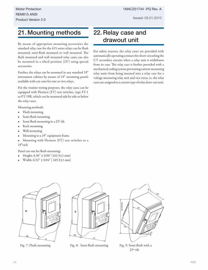
ABB 34
1MAC251744 -PG Rev. A
Issued: 03.01.2010
Motor Protection
REM615 ANSI
Product Version 2.0
Fig. 7: Flush mounting Fig. 8: Semi-fl ush mounting Fig. 9: Semi-fl ush with a 25º tilt
21. Mounting methods
By means of appropriate mounting accessories the standard relay case for the 615 series relays can be fl ush mounted, semi-fl ush mounted or wall mounted. Th e fl ush mounted and wall mounted relay cases can also be mounted in a tilted position (25°) using special accessories.
Further, the relays can be mounted in any standard 19” instrument cabinet by means of 19” mounting panels available with cut-outs for one or two relays.
For the routine testing purposes, the relay cases can be equipped with Flexitest (FT) test switches, type FT-1 or FT-19R, which can be mounted side by side or below the relay cases.
Mounting methods:• Flush mounting• Semi-fl ush mounting• Semi-fl ush mounting in a 25° tilt• Rack mounting• Wall mounting• Mounting to a 19” equipment frame• Mounting with Flexitest (FT) test switches to a 19”rack
Panel cut-out for fl ush mounting: • Height: 6.36” ± 0.04” (161.5±1 mm)• Width: 6.52” ± 0.04” ( 165.5±1 mm)
22. Relay case and drawout unit
For safety reasons, the relay cases are provided with automatically operating contacts for short-circuiting the CT secondary circuits when a relay unit is withdrawn from its case. Th e relay case is further provided with a mechanical coding system preventing current measuring relay units from being inserted into a relay case for a voltage measuring relay unit and vice versa, i.e. the relay cases are assigned to a certain type of relay draw-out unit.

ABB 35
Motor Protection
REM615 ANSI
Product Version 2.0
1MAC251744 -PG Rev. A
Issued: 03.01.2010
23. Selection and ordering data
The relay type and serial number label identifies t h e p r o t e c t i o n r e l a y. T h e l a b e l i s p l a c e d above the HMI on the upper part of the draw-out unit. An order number label is placed on the side of the draw-out unit as well as inside the case. Th e order number consists of a string of alphanumeric characters generated from the hardware and soft ware modules of the relay.
Use the ordering key information in Fig. 10 to generate the order number when ordering complete protection relays.
Example code: H A M C C A C A F F E 1 B N N 1 X C
Your ordering code:
Digit (#) 1 2 3 4 5 6 7 8 9 10 11 12 13 14 15 16 17 18
Code
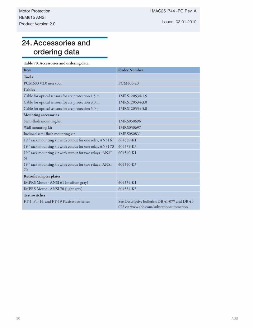
ABB 36
1MAC251744 -PG Rev. A
Issued: 03.01.2010
Motor Protection
REM615 ANSI
Product Version 2.0
24. Accessories and ordering data
Table 70. Accessories and ordering data.
Item Order Number
Tools PCM600 V2.0 user tool PCM600-20CablesCable for optical sensors for arc protection 1.5 m 1MRS120534-1.5Cable for optical sensors for arc protection 3.0 m 1MRS120534-3.0Cable for optical sensors for arc protection 5.0 m 1MRS120534-5.0Mounting accessoriesSemi-fl ush mounting kit 1MRS050696Wall mounting kit 1MRS050697Inclined semi-fl ush mounting kit 1MRS05083119 ” rack mounting kit with cutout for one relay, ANSI 61 604539-K119 ” rack mounting kit with cutout for one relay, ANSI 70 604539-K319 ” rack mounting kit with cutout for two relays , ANSI 61
604540-K1
19 ” rack mounting kit with cutout for two relays , ANSI 70
604540-K3
Retrofi t adapter platesIMPRS Motor - ANSI 61 (medium gray) 604534-K1IMPRS Motor - ANSI 70 (light gray) 604534-K3Test switchesFT-1, FT-14, and FT-19 Flexitest switches See Descriptive bulletins DB 41-077 and DB 41-
078 on www.abb.com/substationautomation

ABB 37
Motor Protection
REM615 ANSI
Product Version 2.0
1MAC251744 -PG Rev. A
Issued: 03.01.2010
25. Tools
Th e relay is delivered as a pre-confi gured unit. Th e default parameter setting values can be changed from the front-panel user interface, the web-browser based user interface (WHMI) or the PCM600 tool in combination with the relay specifi c connectivity package (CP).
PCM600 off ers extensive relay confi guration functions such as relay signal confi guration using the signal matrix tool, and IEC 61850 communication configuration including horizontal relay-to-relay communication, GOOSE.
When the web-browser based user interface is used, the relay can be accessed either locally or remotely using a web browser (IE 6.0 or later). For security reasons, the web-browser based user interface is disabled by default. Th e interface can be enabled with the PCM600 tool or from the front panel user interface. Th e functionality of the interface can be limited to read-only access by means of PCM600.
Confi guration, setting and SA system tools VersionPCM600 2.1 or laterWeb-browser based user interface IE 7.0 or laterREM615 Connectivity Package 2.0 or laterCOM600 substation product V3.4 or laterMicroSCADA Pro Substation Automation system 9.2 SP1 or later
Table 71. Tools

ABB 38
1MAC251744 -PG Rev. A
Issued: 03.01.2010
Motor Protection
REM615 ANSI
Product Version 2.0
26. Terminal diagrams
16
151918
10
111213
14
22
23
24
SO2
TCM-2
PO4
SO1
TCM-1
PO317
21
20
X120
12
3
4
567
89
1011
1213
14IG
IA
IB
BI 4
BI 3
BI 2
BI 1
IC
REM615 ANSI
ABC
S1
S2
P1
P2
52
BA C
X100
67
89
10
2
1
3
45
PO2
PO1
IRF
+
-Vaux
X1LAN
1) 2)
GND1)
GNDC
A/+ RXB/- RXA/+ TXB/- TXAGNDIRIG-B+IRIG-B-
1
109876
X5
432
5
X13Light sensor input 1
1 )
X14
Light sensor input 21 )
X15Light sensor input 3
1 )
1) Optional2) 100BaseFX / LC or 100BaseTX / RJ-45
X130
X110
12
56
7
89
10BI 6
BI 5
BI 4
BI 3
BI 1
BI 8
BI 712
13
11
4 BI 23
12
3
45
6 BI 4
BI 3
BI 2
BI 1
BI 6
BI 58
9
7
1)
X110
16
14
15
19
17
18
22
20
21
SO3
SO2
SO1
24
23SO4
X130
12
10
11
15
13
14
18
16
17
SO3
SO2
SO11)
Figure 10. Terminal diagram for the standard confi guration A
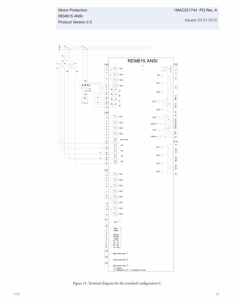
ABB 39
Motor Protection
REM615 ANSI
Product Version 2.0
1MAC251744 -PG Rev. A
Issued: 03.01.2010
16
151918
10
111213
14
22
23
24
SO2
TCM-2
PO4
SO1
TCM-1
PO317
21
20
X120
12
3
4
567
89
1011
1213
14IG
IA
IB
BI 4
BI 3
BI 2
BI 1
IC
X130
12
56
78
9
10
VB
VA
BI 4
BI 3
BI 1
VG
VC
1213
11
REM615 ANSI
ABC
S1
S2
P1
P2
52
BA C
X100
67
89
10
2
1
3
45
PO2
PO1
IRF
+
-Vaux
X110
16
14
15
19
17
18
22
20
21
SO3
SO2
SO1
24
23SO4
4 BI 23
X1LAN
1 ) 2)
GND1)
GNDC
A/+ RXB/- RXA/+ TXB/- TXAGNDIRIG-B+IRIG-B-
1
109876
X5
432
5
X13Light sensor input 1
1)
X14
Light sensor input 21)
X15Light sensor input 3
1)
1) Optional2) 100BaseFX / LC or 100BaseTX / RJ-45
Not in use
16
15
18
17
14
dnda
a
nN
A
X110
12
56
7
89
10BI 6
BI 5
BI 4
BI 3
BI 1
BI 8
BI 712
13
11
4 BI 23
Figure 11. Terminal diagram for the standard confi guration C

ABB 40
1MAC251744 -PG Rev. A
Issued: 03.01.2010
Motor Protection
REM615 ANSI
Product Version 2.0
27. Certifi cates
28. References
KEMA has issued an IEC 61850 Certifi cate Level A1 for REF615. Certifi cate number: 30710144-Consulting 08-0115
Th e REM615 is a UL Listed product per UL File E103204 for these power supply order codes - see Section 23 for Ordering data details.
Th e download area on the right hand side of the web page contains the latest product documentation, such as technical reference manual, installation manual, operators manual,etc. Th e selection tool on the web page helps you fi nd the documents by the document category and language.
Th e Features and Application tabs contain product related information in a compact format.
Th e www.abb.com/substationautomation portal off ers you information about the distribution automation product and service range.
You will fi nd the latest relevant information on the REM615 protection relay on the product page.
Figure 13. Product page
UL Listed Control Voltage/Power Input, V:
REM615 “Power Supply” order code’s 16th character
Operating temperature (ambient) range
24-60 Vdc nominal 2 -25°C to +55°C80-250 Vdc (80-240 Vac) nominal 1 -25°C to +55°C

ABB 41
Motor Protection
REM615 ANSI
Product Version 2.0
1MAC251744 -PG Rev. A
Issued: 03.01.2010
29. Functions, codes and symbols
Table 72. REM615 Functions, codes and symbols
Function IEC 61850 ANSI C37.2-2008Protection
Th ree-phase non-directional time overcurrent PHLPTOC 51P
Th ree-phase non-directional instantaneous overcurrent, low-set, instance 1
PHHPTOC1 50P
Ground non-directional time overcurrent EFLPTOC1 51GNeutral, directional time overcurrent DEFLPDEF1 67/51NCircuit breaker failure protection CCBRBRF 50BF/50NBFMaster trip, instance 1 TRPPTRC1 94/86-1Master trip, instance 2 TRPPTRC2 94/86-2Arc fl ash detection (AFD), instance 1 ARCSARC1 AFD-1Arc fl ash detection (AFD), instance 2 ARCSARC2 AFD-2Arc fl ash detection (AFD), instance 3 ARCSARC3 AFD-3Negative sequence overcurrent protection for motors, instance 1 MNSPTOC1 46M-1Negative sequence overcurrent protection for motors, instance 2 MNSPTOC2 46M-2Loss of load supervision LOFLPTUC 37Motor load jam protection JAMPTOC 51LRMotor start-up supervision STTPMSU 66/51LRSPhase reversal protection PREVPTOC 46RTh ermal overload protection for motors MPTTR 49MTh ree-phase undervoltage protection PHPTUV 27Positive sequence undervoltage protection PSPTUV 27PSNegative sequence overvoltage protection NSPTOV 47ControlCircuit-breaker control CBXCBR1 52Condition MonitoringCircuit-breaker condition monitoring SSCBR1 52CMTrip circuit monitoring, instance 1 TCSSCBR1 TCM-1Trip circuit monitoring, instance 2 TCSSCBR2 TCM-2Current circuit supervision CCRDIF1 CCMFuse failure supervision SEQRFUF1 60Machine run-time counter, instance 1 MDSOPT1 OPTM-1Machine run-time counter, instance 2 MDSOPT2 OPTM-2
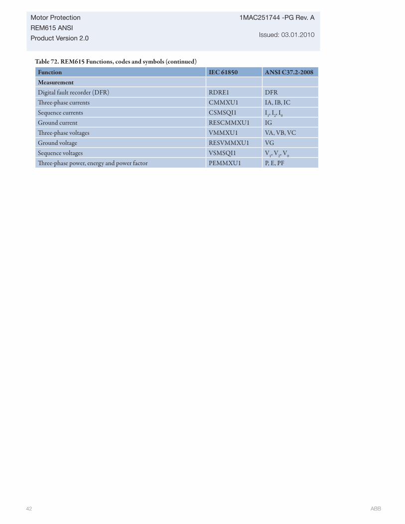
ABB 42
1MAC251744 -PG Rev. A
Issued: 03.01.2010
Motor Protection
REM615 ANSI
Product Version 2.0
Function IEC 61850 ANSI C37.2-2008MeasurementDigital fault recorder (DFR) RDRE1 DFRTh ree-phase currents CMMXU1 IA, IB, ICSequence currents CSMSQI1 I1, I2, I0
Ground current RESCMMXU1 IGTh ree-phase voltages VMMXU1 VA, VB, VCGround voltage RESVMMXU1 VGSequence voltages VSMSQI1 V1, V2, V0
Th ree-phase power, energy and power factor PEMMXU1 P, E, PF
Table 72. REM615 Functions, codes and symbols (continued)

ABB 43
Motor Protection
REM615 ANSI
Product Version 2.0
1MAC251744 -PG Rev. A
Issued: 03.01.2010
30. Document revision history
Table 73. Document revision history
A/ March 01, 2010 V2.0 Initial product version release

ABB 44
1MAC251744 -PG Rev. A
Issued: 03.01.2010
Motor Protection
REM615 ANSI
Product Version 2.0
31. Notes

ABB 45
Motor Protection
REM615 ANSI
Product Version 2.0
1MAC251744 -PG Rev. A
Issued: 03.01.2010
Contact us
1MA
C25
1744
-P
G R
ev.
A M
arch
201
0ABB Inc.Distribution Automation4300 Coral Ridge DriveCoral Springs, Florida 33065Phone: +1 954-752-6700Fax: +1 954-345-5329
www.abb.com/substationautomation
All sales are subject to ABB Inc.General Terms and Conditions of Sale.
While every effort has been made to assure accuracy, the information in this document is subject to change without notice.
© Copyright 2010 ABB Inc. All rights reserved.