Embed Size (px)
Citation preview
Acta of Bioengineering and Biomechanics Original paperVol. 17, No. 2, 2015 DOI: 10.5277/ ABB-00038-2014-02
Remodelling of material structure in aortic valve leaflet
KRZYSZTOF PATRALSKI*, PIOTR KONDERLA
Wrocław University of Technology.
Purpose: The goal of this study is to model changes in fibre content in aortic valve leaflet material due to mechanical stimuli. Meth-ods: The fibre remodelling process is associated with the redistribution of the internal forces acting in the shell. The process is character-ized by the occurrence of extreme stresses and strains. The load distribution function is asymmetrical. The optimization problem hasbeen assigned the task of transferring the load imposed on the leaflet. The density of the fibres per unit surface of the middle shell wasassumed to be proportional to the shell thickness, which means that fibre density along the normal direction is constant over the entireshell. Results: The model of valve leaflet loading is the distribution of the pressure generated on the leaflet shell surface by the flowingfluid. The algorithm for the redistribution of the leaflet material mass made it possible to distinguish two regions of enhanced thicknessin the leaflet shell. One was localized between the commissures along the leaflet attachment, the other one in the middle part of the leaf-let at the level of the commissures. A reduction in shell thickness is observed in the middle part of the leaflet, above the point of its at-tachment to the aorta. Conclusions: The distribution of the thickness field obtained corroborates the findings of the study reported elier.Our study on the remodelling of the valve leaflet entailed the application of the stress criterion, which visibly upgraded the functioning ofthe valve by improving its mechanical and hemodynamic parameters.
Key words: aortic valve, tissue engineering, fibre reinforced material, remodelling
1. Introduction
Remodelling has an important part in the func-tioning of tissues that are responsible for load transfer.The remodelling process is aimed at changing thestructure of a material in order to upgrade its perform-ance. Tissue remodelling is induced by both biologicaland mechanical factors. The latter act as mechanicalstimuli, inducing the remodelling of the tissues whosemain function entails load transfer.
Scientific reasearch into remodelling-related prob-lems takes its roots in the mechanics of the osseoussystem [5]. Many investigators express the opinionthat bone remodelling is predominantly induced bya mechanical stimulus. When a bone tissue is me-chanically induced, its structure undergoes remodel-ling and adapts to the given loading set.
In the literature, much consideration has been de-voted to mechanically induced remodelling of colla-
gen fibres [6], with emphasis on the key importance oftheir synthesis and degradation in the aortic valve [1].Driessen et al. [3] investigated the remodelling ofcollagenous fibres in the leaflet of the aortic valve.They assumed that the fibres are arranged in the di-rections of the principal strains, and that the density ofthe collagen fibres increases with the increase in thenominal strains to which they are exposed.
Driessen et al. [3] proposed a model that describeshow the orientations and densities of the fibres in theaortic valve leaflet change with the progress of themechanically induced remodelling process. They as-sumed that the reorientation of the fibres occurs solelyin two vertical directions. They analyzed the func-tioning of the fibrosa layer (which is built predomi-nantly of collagen fibres), assuming that the bucklingof the leaf shell is symmetrical, and that the scheme ofloading is simple, since in this case use is made ofa homogeneous loading in the form of pressure.Driessen et al. [3] have developed the thesis that fibre
______________________________
* Corresponding author: Krzysztof Patralski, Wrocław University of Technology, ul. Braniborska 21 m. 6, 53-680 Wrocław, Poland.Tel: +48605359432, e-mail: [email protected]
Received: February 24th, 2014Accepted for publication: June 2nd, 2014
K. PATRALSKI, P. KONDERLA64
remodelling on a micro scale results from materialdeformation on a macro scale. The total number offibres increases with the increase in their averagenominal tension. Boerboom et al. [1] modified Dries-sen’s algorithm by including the capacity of the fibresfor reorientation in many directions. The adopted netof fibres of an arbitrary orientation enables remodel-ling via fibre synthesis and degradation, which occurin the natural remodelling process.
The study reported on in this paper furthers ourprevious research into the structure of a physical model,which describes the functioning of natural aortic valvesin terms of continuous medium mechanics. The aim ofthe present study was to develop a novel, originalmethod for describing the remodelling in the aorticvalve leaflet. In terms of mechanics, remodelling is anoptimization problem targeted at obtaining an optimaldistribution of the composite material (matrix-immersed fibres) for the aortic valve leaflet, in orderto enable optimal functioning of the aortic valve in thecirculatory system. The notion ‘optimal functioning ofthe system’ is included in the formal mathematicaldescription of the optimization problem.
A key issue in describing the functioning of theaortic valve is the identification of the material of theaortic valve leaflet [7]. The three-layer structure, thecollagen and elastin fibres, as well as the varying thick-ness of the leaflet shell, indicate that the aortic valve isbest suited for performing the function of a one-wayvalve in the circulatory system.
Our previous investigations have substantiated theimportance of understanding the response of the leaf-let tissues to the mechanical stimulus induced by theflowing fluid. The analysis of the fluid–valve interac-tion provides information about the distribution of theload exerted by the fluid onto the valve, as well asabout the variability of this load with time [8].
A key factor in the remodelling of the leaflet struc-ture is to define the load received by the leaflet; thisload is characterized by distributions, both in space andtime, which take values similar to those observed ina real process. In our present work, the determination ofthe loading exerted on the leaflet was preceded bya number of preliminary analyses of fluid flow througha system where the leaflet acted as a rigid obstacle. Theremodelling process is formulated as an optimizationproblem with an objective function. The remodellingproblem is analyzed using two different objectivefunctions, each of them being physically justified. Oneof the objective functions refers to the rigidity of theleaflet, while the other one (which is the focus of thepresent research) refers to the shear stresses responsiblefor the degradation of the leaflet material.
Using the algorithm established for the purpose ofthe study and a specialized software, numerical analy-ses were performed to describe the remodelling of theaortic valve leaflet. This paper presents a discussionof the most significant results.
2. Materials and methods
Our previous work [7] was focused on analyzingthe mechanical properties and the shell structure of theaortic valve leaflet, the Reul model being adopted asthe initial geometry. The model parameters beingsearched were determined via optimization by mini-mizing the objective function, which in that case wasthe critical pressure. In the present study, the sameclass of valve leaflet geometry is made subject toanalysis for comparative purposes.
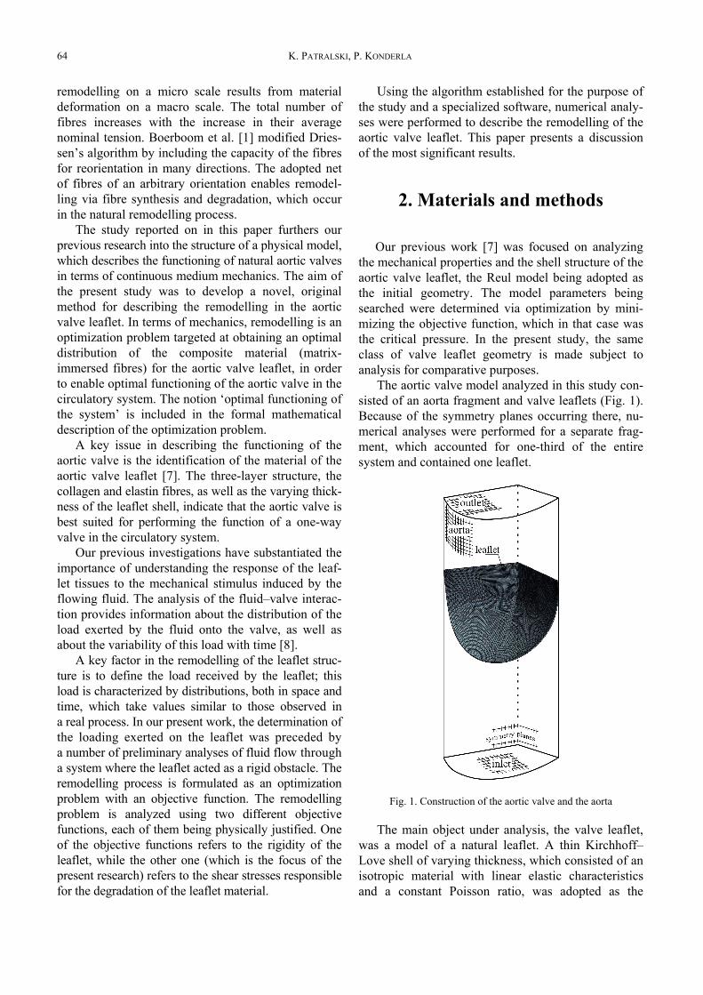
The aortic valve model analyzed in this study con-sisted of an aorta fragment and valve leaflets (Fig. 1).Because of the symmetry planes occurring there, nu-merical analyses were performed for a separate frag-ment, which accounted for one-third of the entiresystem and contained one leaflet.
Fig. 1. Construction of the aortic valve and the aorta
The main object under analysis, the valve leaflet,was a model of a natural leaflet. A thin Kirchhoff–Love shell of varying thickness, which consisted of anisotropic material with linear elastic characteristicsand a constant Poisson ratio, was adopted as the
Remodelling of material structure in aortic valve leaflet 65
physical model of the valve leaflet [7]. The adoptionof a simple model for the description of the valveleaflet does not reduce the generality of the remodel-ling process considered. An essential feature of themodel is the non-homogeneity of the shell, whichundergoes changes in the course of remodelling.
It has been assumed that the leaflet is attachedstiffly to the aorta. The model contains a single leafletonly, so the contact of the leaflet with the other leaf-lets of the valve is not considered directly. This con-tact is considered indirectly while modelling the ge-ometry of the leaflet during the phase of completeclosure of the valve. Aorta is an undeformable cylin-der. The model of the fluid is an incompressibleNewtonian fluid characterized by density ρ and dy-namic viscosity μ. The model is considered to be iso-thermal, viscous and incompressible. The Newtonianmodel of the flow can be well described be Navier–Stockes equation and the continuity equation. Thecharacter of flow is turbulent.
The only load received by the leaflet is the pres-sure of the surrounding fluid. The state of the valve’sclosure is regarded as the initial configuration of thesystem, where the stress in the leaflet shell is zero.The occurrence of potential stresses in the shell at theplace of attachment, or under boundary conditions onthe free edge, was neglected in the initial configura-tion. In the course of the process the load induced bythe pressure of the fluid undergoes changes with time.The structure is loaded both sides. The distribution ofthe load in the form of a non-homogeneous pressuredistribution was obtained by solving (at stage I) theindependent problem of interaction between theflowing fluid and the valve shell, under conditions ofideal homogeneous parameters of the shell.
The fibre remodelling process is associated withthe redistribution of the internal forces acting in theshell while the valve is working. The process is as-sumed to take place only during the systole phase,which is characterized by the occurrence of extremestresses and strains. Because of the non-homogeneousand complex nature of the load distribution, it is nec-essary to take into account the possibility that thebuckling of the leaflet and the distribution of thefunction describing the state of the shell will beasymmetrical.
To obtain numerical solutions, nonlinear-geometricanalyses were performed using the finite elementmethod and (in most instances) the Ansys system.Applying the method of one-way interaction betweenthe fluid and the leaflet structure necessitated theassumption that the fluid affects the shell of the leafletwhereas the shell does not affect the fluid; it only
acts as a rigid obstacle to the fluid (an obstacle witha time-dependent geometry).
The optimization problem consisted in findingthe optimal distribution of the physical structure(density of the net of fibres immersed in the matrix),which has been assigned the task of transferring theload imposed on the leaflet during the valve func-tioning cycles. The density of the fibres per unit sur-face of the middle shell was assumed to be propor-tional to the shell thickness, which means that fibredensity along the normal direction is constant overthe entire shell [9].
The dynamic process being analyzed, formulatedin terms of continuous medium mechanics, was solvednumerically by the finite element method. For theadopted discrete model MES the following designvector variable was defined
T)()()2()1( )...,,...,,,(
maxee hhhh=b (1)
where h(e) is shell thickness on the e-th element.Vector b is a discrete representation of the func-
tion describing the distribution of the leaflet shellthickness, which can also be interpreted as the distri-bution of fibre density per unit surface of the shell.
The optimization algorithm was established at thefollowing additional limitations:• the total mass (volume) of the leaflet shell is
steady,• the local thickness of the shell can vary over a de-
fined range with respect to the average value.The objective function F(b) was the minimum of
the average shear stress in the valve leaflet when thevalve was fully opened. The objective function for-mulated in this way has a significant physical mean-ing. Because of the three-layer structure of the leafletshell, the extreme shear stresses in the middle layercontribute largely to the degree of its effort. In thecase of stress concentration, there is probability thatthe delamination phenomenon, and consequently thedegradation of the shell, will occur.
The optimization problem was solved in twostages.
Stage I
The valve model was analyzed on the assumptionthat the thickness of the leaflet shell h0 is constant,the mechanical parameters of the material beingE = 10 MPa, v = 0.45. Analysis was performed of theprocess of fluid flow through a part of the aorta(multistep analysis). The process was divided intotime steps Δtk (k = 1, 2, ..., n), where Δtk = tk – tk–1. Foreach time step two analyses were performed:
K. PATRALSKI, P. KONDERLA66
• analysis of fluid flow, where the leaflet was con-sidered as a rigid body of a given geometry,
• static analysis of the leaflet shell considered as anelastic body loaded with the fluid pressure result-ing from the analysis of fluid flow,
• in the subsequent time step the geometry of theleaflet was actualized, taking into account the de-formations produced by previous loadings.The geometry of the leaflet was defined by struc-
tural points, which well characterize the state of de-formation at the point in time t.
As a result of calculations, n pressure distributions,pk(x), were obtained, where k = 1, 2, ..., n. These arethe pressure distributions obtained at the end of thek-th time step at the points in time t1, t2, ..., tn. The setof shell load distributions established as shown abovewas used during stage II (Fig. 2).
Stage II
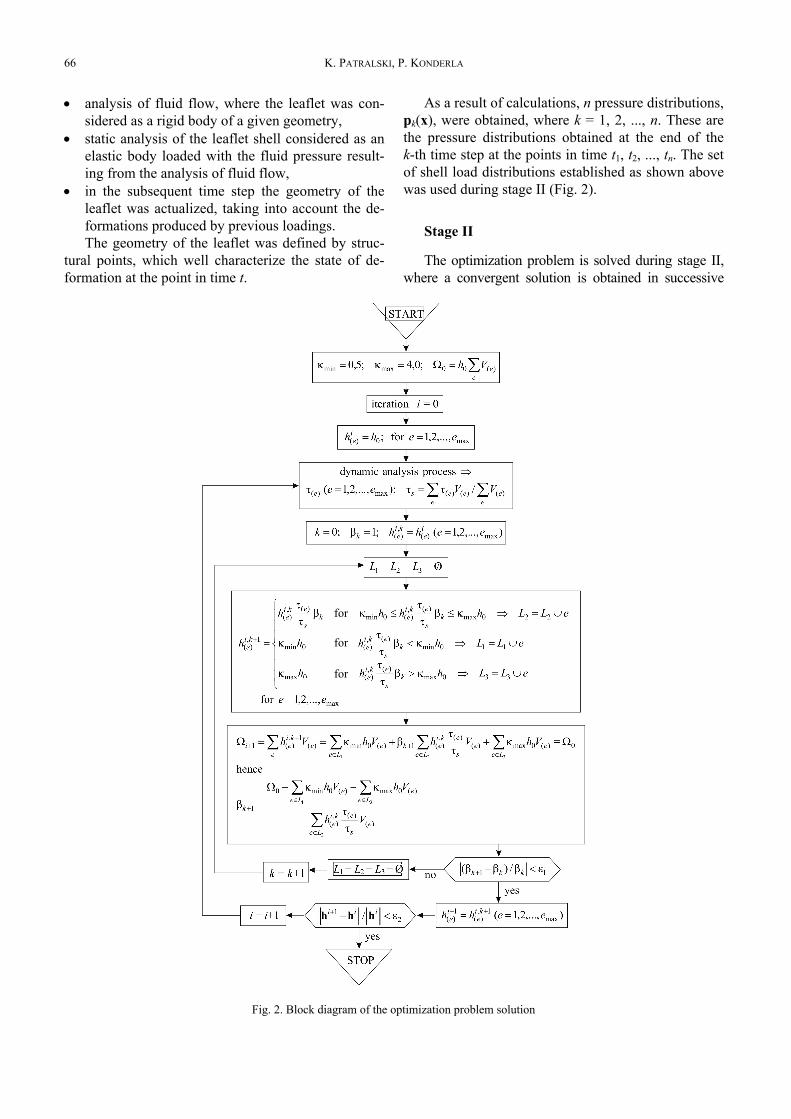
The optimization problem is solved during stage II,where a convergent solution is obtained in successive
Fig. 2. Block diagram of the optimization problem solution
for
for
for
Remodelling of material structure in aortic valve leaflet 67
iterative steps, in accordance with the objective functionassumed.
During each iterative step a dynamic analysis isperformed of the process of valve opening; the load-ing applied consists of the pressure distributions de-rived from stage I. In the subsequent time steps, theloading applied to the shell occurs in the form of pres-sure with the following distribution
p(x, t) = pk(x) for ),( 1 kk ttt −⊂ (2)
and the loading is temporarily constant in the k-thtime step.
Each iterative step involves the following operations:• the distribution of the shell thickness is given: thick-
ness h(e) is sought for each finite element (FE),• the process of valve opening is made subject to
dynamic analysis, with the assumption that loaddistribution is time-dependent: p(x, t). The resultsof analysis are stress and strain distributions ineach particular FE, special consideration beinggiven to the determination of the shear stresses onthe surface of the middle shell, yzxz ττ , , and to thedetermination of the resultant of those stresses,
22max yzxz τττ += , at selected points of the FE,
such as: (a) the centre of the FE, (b) the nodalpoints of the FE, (c) the integration points,
• the average value of the maximal shear stress, τ(e),in the FE is determined,
• the average value of the shear stress on the leafletshell is determined
∑∑=e
ee
ees VV )()()( /ττ ,
• leaflet mass redistribution is obtained by defininga new shell thickness distribution according to theprocedure specified in the block diagram.At the beginning of the iteration process the initial
thickness of the FE is h(e) = h0 in the model.The final point of each iteration step (i.e., the point
in time tf) is determined as follows:• for the first iteration, several points, xj ( j = 1, 2,
..., m), on the free edge of the leaflet are selected;they form the contour of the open leaflet and, atthe same time, constitute the base for the measureof the orifice area during the systole phase equalto A0 (A0 is the area between the extreme radii, Ox1
and Oxm, and the broken curve, which connectsconsecutive points of the set xj),
• during any further iteration, the displacements ofselected points on the leaflet edge are determined,and the orifice area during the systole phase, Ak, is
calculated; this area is selected for the point oftimein such a way that 01.00 =≤− Ak AA ε .Because of the limitations of the optimization prob-
lem, the thicknesses for the particular FE of the shell arechosen by internal iteration. The block diagram of theoptimization problem solution is specified in Fig. 2.
3. Results
The solution to the problem of remodelling a netof collagen fibres being part of the aortic valve leafletstructure was based on two assumptions, which in ouropinion are of importance.
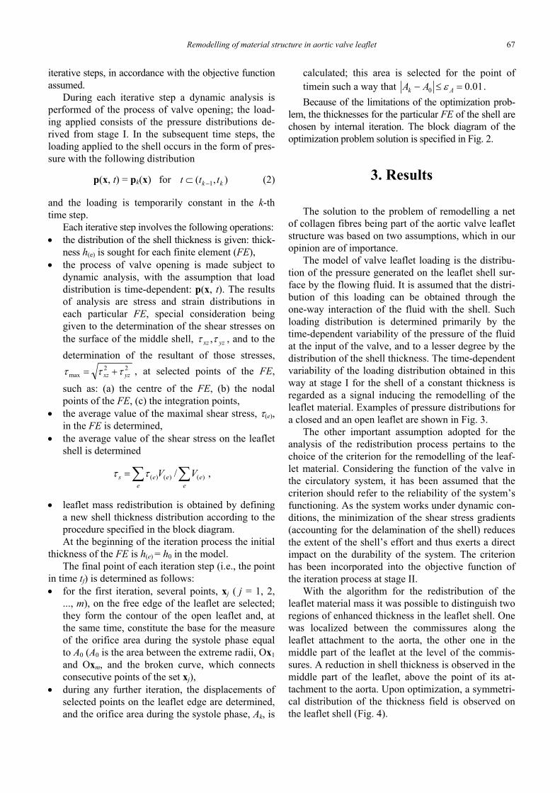
The model of valve leaflet loading is the distribu-tion of the pressure generated on the leaflet shell sur-face by the flowing fluid. It is assumed that the distri-bution of this loading can be obtained through theone-way interaction of the fluid with the shell. Suchloading distribution is determined primarily by thetime-dependent variability of the pressure of the fluidat the input of the valve, and to a lesser degree by thedistribution of the shell thickness. The time-dependentvariability of the loading distribution obtained in thisway at stage I for the shell of a constant thickness isregarded as a signal inducing the remodelling of theleaflet material. Examples of pressure distributions fora closed and an open leaflet are shown in Fig. 3.
The other important assumption adopted for theanalysis of the redistribution process pertains to thechoice of the criterion for the remodelling of the leaf-let material. Considering the function of the valve inthe circulatory system, it has been assumed that thecriterion should refer to the reliability of the system’sfunctioning. As the system works under dynamic con-ditions, the minimization of the shear stress gradients(accounting for the delamination of the shell) reducesthe extent of the shell’s effort and thus exerts a directimpact on the durability of the system. The criterionhas been incorporated into the objective function ofthe iteration process at stage II.
With the algorithm for the redistribution of theleaflet material mass it was possible to distinguish tworegions of enhanced thickness in the leaflet shell. Onewas localized between the commissures along theleaflet attachment to the aorta, the other one in themiddle part of the leaflet at the level of the commis-sures. A reduction in shell thickness is observed in themiddle part of the leaflet, above the point of its at-tachment to the aorta. Upon optimization, a symmetri-cal distribution of the thickness field is observed onthe leaflet shell (Fig. 4).
K. PATRALSKI, P. KONDERLA68
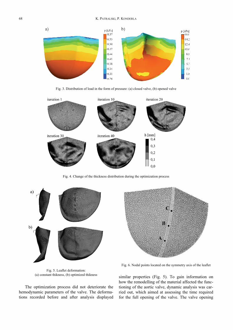
Fig. 5. Leaflet deformation:(a) constant thikness, (b) optimized thikness
The optimization process did not deteriorate thehemodynamic parameters of the valve. The deforma-tions recorded before and after analysis displayed
similar properties (Fig. 5). To gain information onhow the remodelling of the material affected the func-tioning of the aortic valve, dynamic analysis was car-ried out, which aimed at assessing the time requiredfor the full opening of the valve. The valve opening
Fig. 3. Distribution of load in the form of pressure: (a) closed valve, (b) opened valve
Fig. 4. Change of the thickness distribution during the optimization process
Fig. 6. Nodal points located on the symmetry axis of the leaflet
Remodelling of material structure in aortic valve leaflet 69
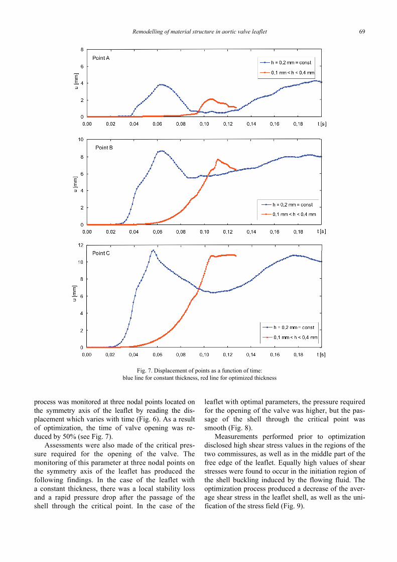
process was monitored at three nodal points located onthe symmetry axis of the leaflet by reading the dis-placement which varies with time (Fig. 6). As a resultof optimization, the time of valve opening was re-duced by 50% (see Fig. 7).
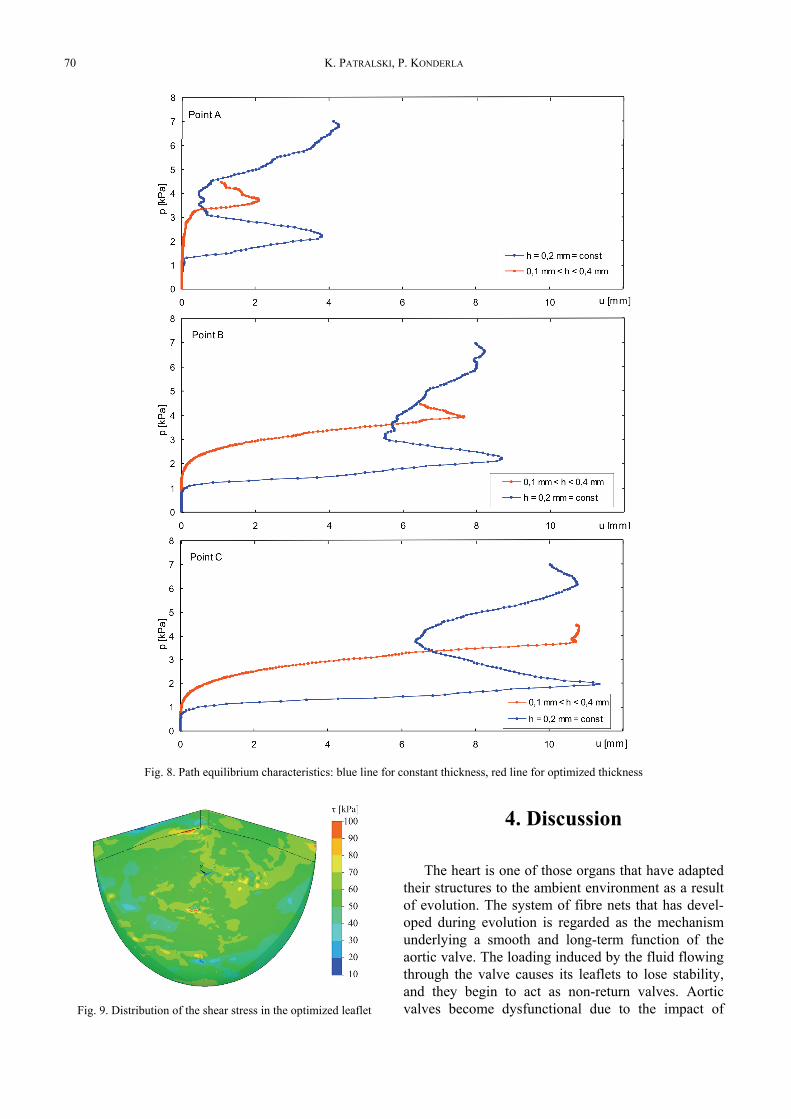
Assessments were also made of the critical pres-sure required for the opening of the valve. Themonitoring of this parameter at three nodal points onthe symmetry axis of the leaflet has produced thefollowing findings. In the case of the leaflet witha constant thickness, there was a local stability lossand a rapid pressure drop after the passage of theshell through the critical point. In the case of the
leaflet with optimal parameters, the pressure requiredfor the opening of the valve was higher, but the pas-sage of the shell through the critical point wassmooth (Fig. 8).
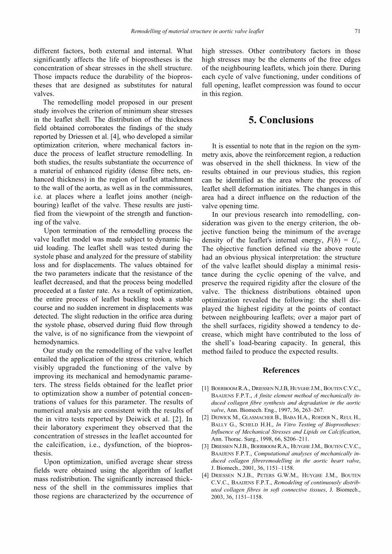
Measurements performed prior to optimizationdisclosed high shear stress values in the regions of thetwo commissures, as well as in the middle part of thefree edge of the leaflet. Equally high values of shearstresses were found to occur in the initiation region ofthe shell buckling induced by the flowing fluid. Theoptimization process produced a decrease of the aver-age shear stress in the leaflet shell, as well as the uni-fication of the stress field (Fig. 9).
Fig. 7. Displacement of points as a function of time:blue line for constant thickness, red line for optimized thickness
K. PATRALSKI, P. KONDERLA70
Fig. 9. Distribution of the shear stress in the optimized leaflet
4. Discussion
The heart is one of those organs that have adaptedtheir structures to the ambient environment as a resultof evolution. The system of fibre nets that has devel-oped during evolution is regarded as the mechanismunderlying a smooth and long-term function of theaortic valve. The loading induced by the fluid flowingthrough the valve causes its leaflets to lose stability,and they begin to act as non-return valves. Aorticvalves become dysfunctional due to the impact of
Fig. 8. Path equilibrium characteristics: blue line for constant thickness, red line for optimized thickness
Remodelling of material structure in aortic valve leaflet 71
different factors, both external and internal. Whatsignificantly affects the life of bioprostheses is theconcentration of shear stresses in the shell structure.Those impacts reduce the durability of the biopros-theses that are designed as substitutes for naturalvalves.
The remodelling model proposed in our presentstudy involves the criterion of minimum shear stressesin the leaflet shell. The distribution of the thicknessfield obtained corroborates the findings of the studyreported by Driessen et al. [4], who developed a similaroptimization criterion, where mechanical factors in-duce the process of leaflet structure remodelling. Inboth studies, the results substantiate the occurrence ofa material of enhanced rigidity (dense fibre nets, en-hanced thickness) in the region of leaflet attachmentto the wall of the aorta, as well as in the commissures,i.e. at places where a leaflet joins another (neigh-bouring) leaflet of the valve. These results are justi-fied from the viewpoint of the strength and function-ing of the valve.
Upon termination of the remodelling process thevalve leaflet model was made subject to dynamic liq-uid loading. The leaflet shell was tested during thesystole phase and analyzed for the pressure of stabilityloss and for displacements. The values obtained forthe two parameters indicate that the resistance of theleaflet decreased, and that the process being modelledproceeded at a faster rate. As a result of optimization,the entire process of leaflet buckling took a stablecourse and no sudden increment in displacements wasdetected. The slight reduction in the orifice area duringthe systole phase, observed during fluid flow throughthe valve, is of no significance from the viewpoint ofhemodynamics.
Our study on the remodelling of the valve leafletentailed the application of the stress criterion, whichvisibly upgraded the functioning of the valve byimproving its mechanical and hemodynamic parame-ters. The stress fields obtained for the leaflet priorto optimization show a number of potential concen-trations of values for this parameter. The results ofnumerical analysis are consistent with the results ofthe in vitro tests reported by Deiwick et al. [2]. Intheir laboratory experiment they observed that theconcentration of stresses in the leaflet accounted forthe calcification, i.e., dysfunction, of the biopros-thesis.
Upon optimization, unified average shear stressfields were obtained using the algorithm of leafletmass redistribution. The significantly increased thick-ness of the shell in the commissures implies thatthose regions are characterized by the occurrence of
high stresses. Other contributory factors in thosehigh stresses may be the elements of the free edgesof the neighbouring leaflets, which join there. Duringeach cycle of valve functioning, under conditions offull opening, leaflet compression was found to occurin this region.
5. Conclusions
It is essential to note that in the region on the sym-metry axis, above the reinforcement region, a reductionwas observed in the shell thickness. In view of theresults obtained in our previous studies, this regioncan be identified as the area where the process ofleaflet shell deformation initiates. The changes in thisarea had a direct influence on the reduction of thevalve opening time.
In our previous research into remodelling, con-sideration was given to the energy criterion, the ob-jective function being the minimum of the averagedensity of the leaflet's internal energy, F(b) = Us.The objective function defined via the above routehad an obvious physical interpretation: the structureof the valve leaflet should display a minimal resis-tance during the cyclic opening of the valve, andpreserve the required rigidity after the closure of thevalve. The thickness distributions obtained uponoptimization revealed the following: the shell dis-played the highest rigidity at the points of contactbetween neighbouring leaflets; over a major part ofthe shell surfaces, rigidity showed a tendency to de-crease, which might have contributed to the loss ofthe shell’s load-bearing capacity. In general, thismethod failed to produce the expected results.
References
[1] BOERBOOM R.A., DRIESSEN N.J.B, HUYGHE J.M., BOUTEN C.V.C.,BAAIJENS F.P.T., A finite element method of mechanically in-duced collagen fibre synthesis and degradation in the aorticvalve, Ann. Biomech. Eng., 1997, 36, 263–267.
[2] DEIWICK M., GLASMACHER B., BABA H.A., ROEDER N., REUL H.,BALLY G., SCHELD H.H., In Vitro Testing of Bioprostheses:Influence of Mechanical Stresses and Lipids on Calcification,Ann. Thorac. Surg., 1998, 66, S206–211.
[3] DRIESSEN N.J.B., BOERBOOM R.A., HUYGHE J.M., BOUTEN C.V.C.,BAAIJENS F.P.T., Computational analyses of mechanically in-duced collagen fibreremodelling in the aortic heart valve,J. Biomech., 2001, 36, 1151–1158.
[4] DRIESSEN N.J.B., PETERS G.W.M., HUYGHE J.M., BOUTENC.V.C., BAAIJENS F.P.T., Remodeling of continuously distrib-uted collagen fibres in soft connective tissues, J. Biomech.,2003, 36, 1151–1158.

K. PATRALSKI, P. KONDERLA72
[5] HUISKES R., RUIMERMAN R., Effects of mechanical forces onmaintenance and adaptation of form in trabecular bone, Nature,2000, 405, 704–706.
[6] HUMPHREY J.D., Remodelling of collagenous tissue at fixedlengths, J. Biomech. Eng., 1999, 121, 591–597.
[7] KONDERLA P., PATRALSKI K.P., Identification of the aortic leafletvalve material, Proc. App. Math. Mech., 2006, 6, 135–136.
[8] KONDERLA P., PATRALSKI K., Optimizing the shape of theprosthetic aortic leaflet valve, Comp. Assist. Mech. and Eng.Sci., 2006, 13, 557–564.
[9] WELLS S.M., SELLARO T., SACKS M.S., Cyclic loading re-sponse of bioprosthetic heart valves: effects of fixation stressstate on the collagen fiber architecture, Biomat., 2005, 26,2611–2619.