Embed Size (px)
Citation preview
Instruction Sheet 5081C-HTLIQ_MAN_ABR_5081C-HT/Rev.G January 2015
Remote Controlled HART® SMART™
Two-Wire Conductivity Transmitter
WARNING
Substitution of components may impair Intrinsic Safety orsuitability for division 2.
WARNING
do not remove or replace while circuit is live unless area isknown to be non-hazardous.
WARNING
explosion Hazard - do not disconnect equipment unless areais known to be non-hazardous.
WARNING
To prevent ignition of flammable or combustible atmos-pheres, disconnect power before servicing or understand andadhere to the manufacturer's live maintenance procedures.
SpeCIAl CoNdITIoN FoR INTRINSICAlly SAFe USe
The 5081 enclosure is made of aluminum alloy and given aprotective polyurethane finish; however, care must be takento protect it from impact, abrasion or friction with othermetal surfaces if located in zone 0.
WARNING
If a Model 475 Universal Hart® Communicator is used withthese transmitters, the software within the Model 475 mayrequire modification.
If a software modification is required, please contact yourlocal Fisher-Rosemount Service Group or National ResponseCenter at 1-800-654-7768.
ESSENTIAL INSTRUCTIONSRead this page before proceeding!Your purchase from Rosemount Analytical, Inc. has resulted in one of the finest instruments available for your particularapplication. These instruments have been designed, and tested to meet many national and international standards.Experience indicates that its performance is directly related to the quality of the installation and knowledge of the user inoperating and maintaining the instrument. To ensure their continued operation to the design specifications, personnelshould read this manual thoroughly before proceeding with installation, commissioning, operation, and maintenance ofthis instrument. If this equipment is used in a manner not specified by the manufacturer, the protection provided by itagainst hazards may be impaired.
• Failure to follow the proper instructions may cause any one of the following situations to occur: Loss of life; personalinjury; property damage; damage to this instrument; and warranty invalidation.
• Ensure that you have received the correct model and options from your purchase order. Verify that this manualcovers your model and options. If not, call 1-800-854-8257 or 949-757-8500 to request correct manual.
• For clarification of instructions, contact your Rosemount representative.
• Follow all warnings, cautions, and instructions marked on and supplied with the product.
• Use only qualified personnel to install, operate, update, program and maintain the product.
• Educate your personnel in the proper installation, operation, and maintenance of the product.
• Install equipment as specified in the Installation section of this manual. Follow appropriate local and national codes.Only connect the product to electrical and pressure sources specified in this manual.
• Use only factory documented components for repair. Tampering or unauthorized substitution of parts andprocedures can affect the performance and cause unsafe operation of your process.
• All equipment doors must be closed and protective covers must be in place unless qualified personnel areperforming maintenance.
• If this equipment is used in a manner not specified by the manufacturer, the protection provided by it againsthazards may be impaired.
2
5081C-HT Instruction SheetJanuary 2015 LIQ_MAN_ABR_5081C-HT/Rev.G
Specifications
pHySICAl SpeCIFICATIoNS
Housing: Cast aluminum with epoxy coating. Type 4X
(IP65). Neoprene O-ring cover seals. 160.5 mm x 175.3 mm
x 161.3 mm (6.3 in. x 6.9 in. x 6.4 in.)
diameter: 155.4 mm (6.1 in.)
electrical Conduit openings: 3/4 in. FNPT
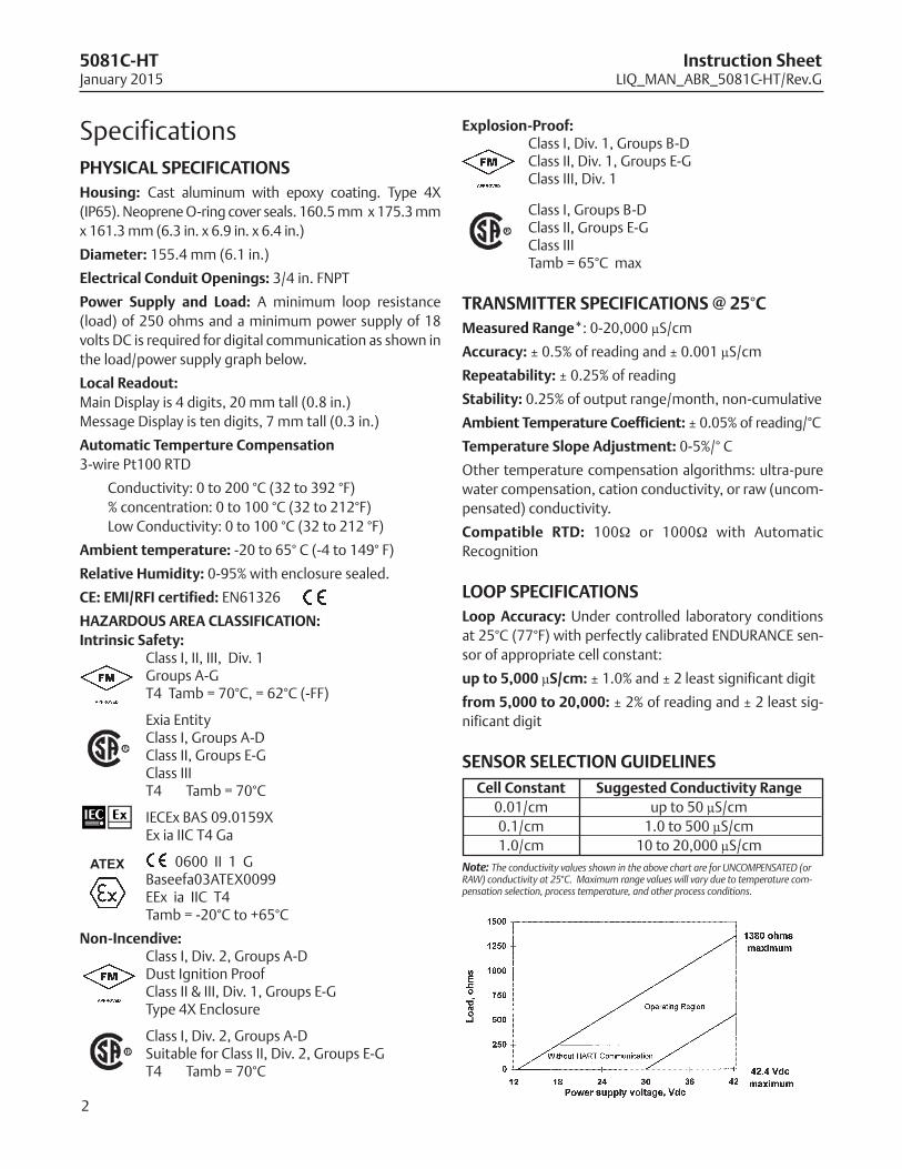
power Supply and load: A minimum loop resistance
(load) of 250 ohms and a minimum power supply of 18
volts DC is required for digital communication as shown in
the load/power supply graph below.
local Readout:
Main Display is 4 digits, 20 mm tall (0.8 in.)
Message Display is ten digits, 7 mm tall (0.3 in.)
Automatic Temperture Compensation
3-wire Pt100 RTD
Conductivity: 0 to 200 °C (32 to 392 °F)
% concentration: 0 to 100 °C (32 to 212°F)
Low Conductivity: 0 to 100 °C (32 to 212 °F)
Ambient temperature: -20 to 65° C (-4 to 149° F)
Relative Humidity: 0-95% with enclosure sealed.
Ce: eMI/RFI certified: EN61326
HAzARdoUS AReA ClASSIFICATIoN:
Intrinsic Safety:Class I, II, III, Div. 1 Groups A-GT4 Tamb = 70°C, = 62°C (-FF)
Exia EntityClass I, Groups A-DClass II, Groups E-GClass IIIT4 Tamb = 70°C
IECEx BAS 09.0159XEx ia IIC T4 Ga
0600 II 1 GBaseefa03ATEX0099EEx ia IIC T4Tamb = -20°C to +65°C
Non-Incendive: Class I, Div. 2, Groups A-DDust Ignition ProofClass II & III, Div. 1, Groups E-GType 4X Enclosure
Class I, Div. 2, Groups A-DSuitable for Class II, Div. 2, Groups E-GT4 Tamb = 70°C
explosion-proof: Class I, Div. 1, Groups B-DClass II, Div. 1, Groups E-GClass III, Div. 1
Class I, Groups B-DClass II, Groups E-GClass IIITamb = 65°C max
TRANSMITTeR SpeCIFICATIoNS @ 25°C
Measured Range*: 0-20,000 µS/cm
Accuracy: ± 0.5% of reading and ± 0.001 µS/cm
Repeatability: ± 0.25% of reading
Stability: 0.25% of output range/month, non-cumulative
Ambient Temperature Coefficient: ± 0.05% of reading/°C
Temperature Slope Adjustment: 0-5%/° C
Other temperature compensation algorithms: ultra-pure
water compensation, cation conductivity, or raw (uncom-
pensated) conductivity.
Compatible RTd: 100W or 1000W with Automatic
Recognition
loop SpeCIFICATIoNS
loop Accuracy: Under controlled laboratory conditions
at 25°C (77°F) with perfectly calibrated ENDURANCE sen-
sor of appropriate cell constant:
up to 5,000 µS/cm: ± 1.0% and ± 2 least significant digit
from 5,000 to 20,000: ± 2% of reading and ± 2 least sig-
nificant digit
SeNSoR SeleCTIoN GUIdelINeS
Note: The conductivity values shown in the above chart are for UNCOMPENSATED (orRAW) conductivity at 25°C. Maximum range values will vary due to temperature com-pensation selection, process temperature, and other process conditions.
ATEX
Cell Constant Suggested Conductivity Range
0.01/cm up to 50 µS/cm
0.1/cm 1.0 to 500 µS/cm
1.0/cm 10 to 20,000 µS/cm
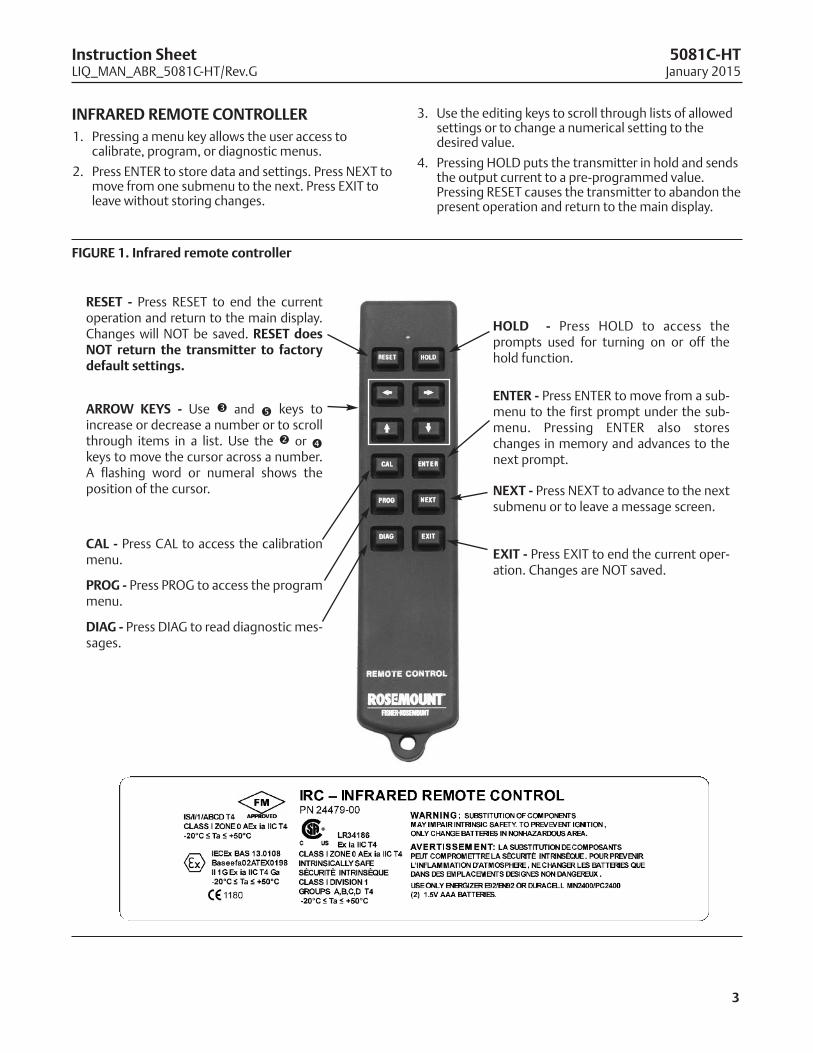
INFRARed ReMoTe CoNTRolleR
1. Pressing a menu key allows the user access tocalibrate, program, or diagnostic menus.
2. Press ENTER to store data and settings. Press NEXT tomove from one submenu to the next. Press EXIT toleave without storing changes.
3
Instruction Sheet 5081C-HTLIQ_MAN_ABR_5081C-HT/Rev.G January 2015
FIGURe 1. Infrared remote controller
3. Use the editing keys to scroll through lists of allowedsettings or to change a numerical setting to thedesired value.
4. Pressing HOLD puts the transmitter in hold and sendsthe output current to a pre-programmed value.Pressing RESET causes the transmitter to abandon thepresent operation and return to the main display.
ReSeT - Press RESET to end the currentoperation and return to the main display.Changes will NOT be saved. ReSeT doesNoT return the transmitter to factorydefault settings.
CAl - Press CAL to access the calibrationmenu.
pRoG - Press PROG to access the programmenu.
dIAG - Press DIAG to read diagnostic mes-sages.
Hold - Press HOLD to access theprompts used for turning on or off thehold function.
ARRoW KeyS - Use é and ê keys toincrease or decrease a number or to scrollthrough items in a list. Use the ç or èkeys to move the cursor across a number.A flashing word or numeral shows theposition of the cursor.
eNTeR - Press ENTER to move from a sub-menu to the first prompt under the sub-menu. Pressing ENTER also storeschanges in memory and advances to thenext prompt.
NeXT - Press NEXT to advance to the nextsubmenu or to leave a message screen.
eXIT - Press EXIT to end the current oper-ation. Changes are NOT saved.
4
5081C-HT Instruction SheetJanuary 2015 LIQ_MAN_ABR_5081C-HT/Rev.G
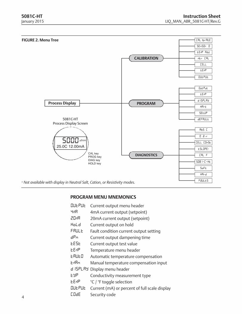
pRoGRAM MeNU MNeMoNICS
500025.0C 12.00mA
CAL keyPROG keyDIAG keyHOLD key
5081C-HT Process Display Screen
µS/cm
pRoGRAM
FIGURe 2. Menu Tree
CAlIbRATIoN
dIAGNoSTICS
process display
Mtr CAL
tEMP
AbS C
0 air
5081-C-Ht
CELL COnSt
SoFt
CAL F
HArd
tSLOPE1
FaULTs
CALIbrAtE
CELL
SEnSOr 0
tEMP AdJ
tEMP
dISPLAY
HArt
SEtUP
dEFAULT
OutPut
OUtPUt
1 Not available with display in Neutral Salt, Cation, or Resistivity modes.
OUtPUt Current output menu header
4MA 4mA current output (setpoint)
20MA 20mA current output (setpoint)
HoLd Current output on hold
FAULt Fault condition current output setting
dPn Current output dampening time
tESt Current output test value
tEMP Temperature menu header
tAUtO Automatic temperature compensation
tMAn Manual temperature compensation input
dISPLAY Display menu header
tYP Conductivity measurement type
tEMP °C / °F toggle selection
OUtPUt Current (mA) or percent of full scale display
COdE Security code
5
Instruction Sheet 5081C-HTLIQ_MAN_ABR_5081C-HT/Rev.G January 2015
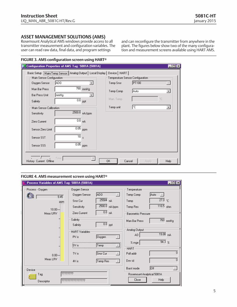
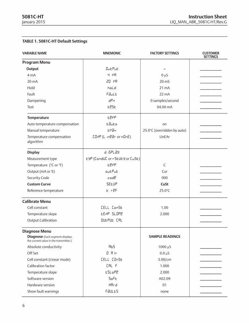
ASSeT MANAGeMeNT SolUTIoNS (AMS)Rosemount Analytical AMS windows provide access to alltransmitter measurement and configuration variables. Theuser can read raw data, final data, and program settings
FIGURe 3. AMS configuration screen using HART®
and can reconfigure the transmitter from anywhere in theplant. The figures below show two of the many configura-tion and measurement screens available using HART AMS.
FIGURe 4. AMS measurement screen using HART®
6
5081C-HT Instruction SheetJanuary 2015 LIQ_MAN_ABR_5081C-HT/Rev.G
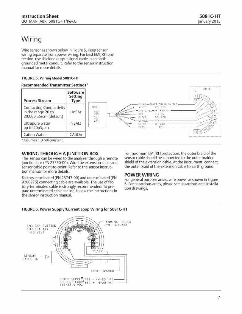
VARIAble NAMe MNeMoNIC FACToRy SeTTINGS CUSToMeR SeTTINGS
program Menu
output Output – ___________
4 mA 4 mA 0 µS ___________
20 mA 20 mA 20 mS ___________
Hold hold 21 mA ___________
Fault fault 22 mA ___________
Dampening dpn 0 samples/second ___________
Test test 04.00 mA ___________
Temperature temp
Auto temperature compensation tauto on ___________
Manual temperature tman 25.0°C (overridden by auto) ___________
Temperature compensation COMP (Linear or nOnE) LInEAr ___________
algorithm
display display
Measurement type typ (CondUC or RSTVTY or Cust)
Temperature (°C or °F) temp C ___________
Output (mA or %) output Cur ___________
Security Code code 000 ___________
Custom Curve SEtUP CuSt ___________
Reference temperature t ref 25.0°C ___________
Calibrate Menu
Cell constant CELL Const 1.00 ___________
Temperature slope tEMP slOpe 2.000 ___________
Output Calibration OUtPUt CAL ___________
diagnose Menu
diagnose (Each segment displays SAMple ReAdINGSthe current value in the transmitter.)
Absolute conductivity Abs 1000 µS ___________
Off Set 0 AIR 0.0 µS ___________
Cell constant (Linear mode) CELL COnSt 3.00/cm ___________
Calibration factor CAL F 1.000 ___________
Temperature slope tslope 2.000 ___________
Software version soft A02.09 ___________
Hardware version HArd 01 ___________
Show fault warnings FaULTS none ___________
TAble 1. 5081C-HT default Settings
7
Instruction Sheet 5081C-HTLIQ_MAN_ABR_5081C-HT/Rev.G January 2015
Wiring
Wire sensor as shown below in Figure 5. Keep sensorwiring separate from power wiring. For best EMI/RFI pro-tection, use shielded output signal cable in an earth-grounded metal conduit. Refer to the sensor instructionmanual for more details.
FIGURe 5. Wiring Model 5081C-HT
FIGURe 6. power Supply/Current loop Wiring for 5081C-HT
WIRING THRoUGH A jUNCTIoN boXThe sensor can be wired to the analyzer through a remotejunction box (PN 23550-00). Wire the extension cable andsensor cable point-to-point. Refer to the sensor instruc-tion manual for more details.
Factory-terminated (PN 23747-00) and unterminated (PN9200275) connecting cable are available. The use of fac-tory-terminated cable is strongly recommended. To pre-pare unterminated cable for use, follow the instructions inthe sensor instruction manual.
Recommended Transmitter Settings*
*Assumes 1.0 cell constant.
SoftwareSetting
process Stream Type
Contacting Conductivityin the range 20 to LInEAr20,000 mS/cm (default)
Ultrapure water n SALtup to 20mS/cm
Cation Water CAtiOn
For maximum EMI/RFI protection, the outer braid of thesensor cable should be connected to the outer braidedshield of the extension cable. At the instrument, connectthe outer braid of the extension cable to earth ground.
poWeR WIRINGFor general purpose areas, wire power as shown in Figure6. For hazardous areas, please see hazardous area installa-tion drawings.
8
5081C-HT Instruction SheetJanuary 2015 LIQ_MAN_ABR_5081C-HT/Rev.G
Installation
UNpACKING ANd INSpeCTIoN Inspect the shipping container. If it is damaged, contactthe shipper immediately for instructions. Save the box. Ifthere is no apparent damage, unpack the container. Besure all items shown on the packing list are present. Ifitems are missing, notify us immediately.
RoTATING THe dISplAy The Model 5081C-HT display can be rotated 90° left orright. Disengage the cover lock and remove the frontcover. Remove the three screws holding the PCB stack andgently lift the display board. Do not disengage the ribboncable between the display board and the CPU board.Rotate the display. The black infrared sensor will be at thetop of the display.
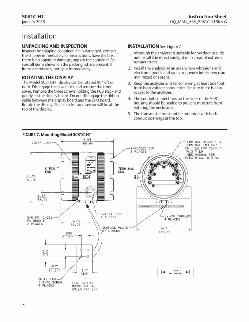
INSTAllATIoN See Figure 7
1. Although the analyzer is suitable for outdoor use, donot install it in direct sunlight or in areas of extremetemperatures.
2. Install the analyzer in an area where vibrations andelectromagnetic and radio frequency interference areminimized or absent.
3. Keep the analyzer and sensor wiring at least one footfrom high voltage conductors. Be sure there is easyaccess to the analyzer.
4. The conduit connections on the sides of the 5081housing should be sealed to prevent moisture fromentering the enclosure.
5. The transmitter must not be mounted with bothconduit openings at the top.
FIGURe 7. Mounting Model 5081C-HT
INCH
MILLIMETER
9
Instruction Sheet 5081C-HTLIQ_MAN_ABR_5081C-HT/Rev.G January 2015
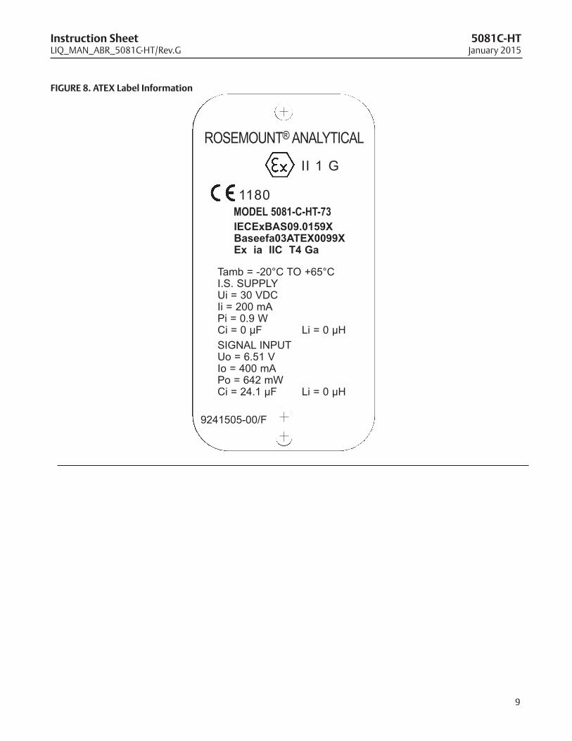
9241505-00/F
ROSEMOUNT® ANALYTICAL
Tamb = -20°C TO +65°CI.S. SUPPLYUi = 30 VDCIi = 200 mAPi = 0.9 WCi = 0 µF Li = 0 µH
SIGNAL INPUTUo = 6.51 VIo = 400 mAPo = 642 mWCi = 24.1 µF Li = 0 µH
1180 MODEL 5081-C-HT-73IECExBAS09.0159XBaseefa03ATEX0099XEx ia IIC T4 Ga
II 1 G
FIGURe 8. ATeX label Information
10
5081C-HT Instruction SheetJanuary 2015 LIQ_MAN_ABR_5081C-HT/Rev.G
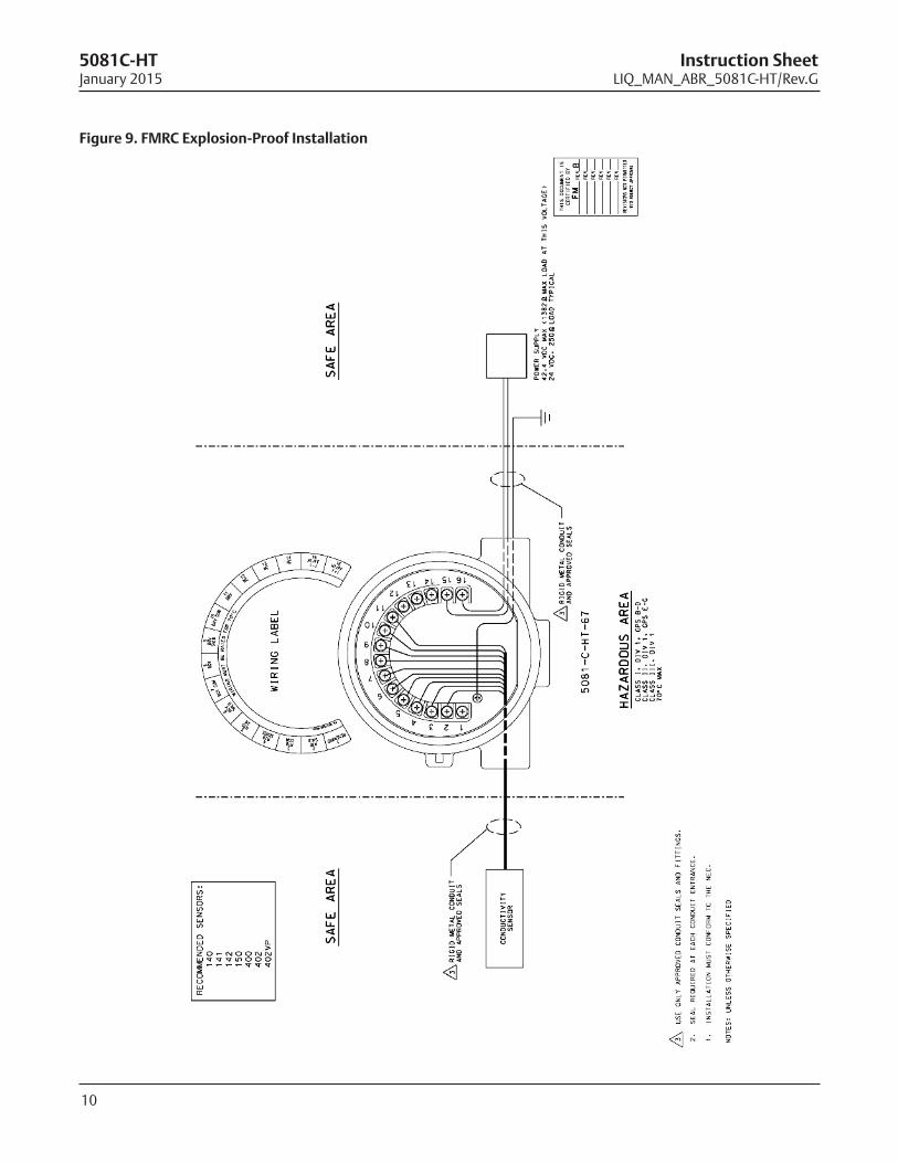
Figure 9. FMRC explosion-proof Installation
11
Instruction Sheet 5081C-HTLIQ_MAN_ABR_5081C-HT/Rev.G January 2015
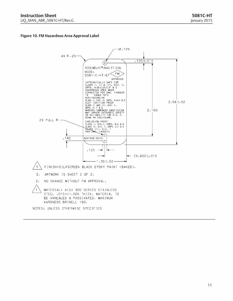
Figure 10. FM Hazardous Area Approval label
5.
DU
ST-T
IGH
T C
ON
DU
IT S
EAL
MU
ST B
E U
SED
WH
EN IN
STA
LLED
IN C
LASS
II A
ND
CLA
SS II
I EN
VIR
ON
MEN
TS.
6.
RES
ISTA
NC
E BE
TWEE
N IN
TRIN
SIC
ALL
Y SA
FE G
RO
UN
D A
ND
EA
RTH
GR
OU
ND
MU
ST B
E LE
SS T
HA
N 1
.0 O
hm
.
10.
TH
E A
SSO
CIA
TED
APP
AR
ATU
S M
UST
BE
FM A
PPR
OV
ED.
1.
AN
Y SH
UN
T ZE
NER
DIO
DE
SAFE
TY B
AR
RIE
R A
PPR
OV
ED B
Y FM
HA
VIN
G T
HE
FOLL
OW
ING
OU
TPU
T PA
RA
MET
ERS:
SUPP
LY/ S
IGN
AL
TER
MIN
ALS
TB1
-15,
16
Vo
c O
R V
t N
OT
GR
EATE
R T
HA
N 3
0 V
Isc
OR
It N
OT
GR
EATE
R T
HA
N 2
00 m
A
Pm
ax
NO
T G
REA
TER
TH
AN
0.9
W
2.
INTR
INSI
CA
LLY
SAFE
APP
AR
ATU
S (M
OD
EL 5
081-
C-H
T, IR
C T
RA
NSM
ITTE
R A
ND
MO
DEL
275
/375
/475
) A
ND
ASS
OC
IATE
D A
PPA
RA
TUS
(SA
FETY
BA
RR
IER
) SH
ALL
MEE
T TH
E FO
LLO
WIN
G R
EQU
IREM
ENTS
:
TH
E V
OLT
AG
E (V
ma
x) A
ND
CU
RR
ENT
(Ima
x) O
F TH
E IN
TRIN
SIC
ALL
Y SA
FE A
PPA
RA
TUS
MU
ST B
E EQ
UA
L TO
OR
GR
EATE
R T
HA
N T
HE
VO
LTA
GE
(Vo
c O
R V
t) A
ND
CU
RR
ENT
(Isc
OR
It)
WH
ICH
CA
N B
E D
ELIV
ERED
BY
THE
ASS
OC
IATE
D A
PPA
RA
TUS
(SA
FETY
BA
RR
IER
). IN
AD
DIT
ION
, TH
E M
AX
IMU
M U
NPR
OTE
CTE
D C
APA
CIT
AN
CE
(Ci)
AN
D IN
DU
CTA
NC
E (L
i) O
F TH
E IN
TRIN
SIC
ALL
Y SA
FE A
PPA
RA
TUS,
INC
LUD
ING
INTE
RC
ON
NEC
TIN
G W
IRIN
G,
MU
ST B
E EQ
UA
L O
R L
ESS
THA
N T
HE
CA
PAC
ITA
NC
E (C
a)
AN
D IN
DU
CTA
NC
E (L
a)
WH
ICH
CA
N B
E SA
FELY
CO
NN
ECTE
D T
O T
HE
APP
AR
ATU
S. (
REF
. TA
BLES
I, II
AN
D II
I). T
HE
CA
PAC
ITA
NC
E A
ND
IND
UC
TAN
CE
OF
THE
LOA
D C
ON
NEC
TED
TO
TH
E SE
NSO
R T
ERM
INA
LS M
UST
NO
T EX
CEE
D T
HE
VA
LUES
SPE
CIF
IED
IN T
ABL
E I.
8.
ASS
OC
IATE
D A
PPA
RA
TUS
MA
NU
FAC
TUR
ER'S
INST
ALL
ATI
ON
DRA
WIN
G M
UST
BE
FOLL
OW
ED
W
HEN
INST
ALL
ING
TH
IS E
QU
IPM
ENT.
7.
TH
E EN
TITY
CO
NC
EPT
ALL
OW
S IN
TER
CO
NN
ECTI
ON
OF
INTR
INSI
CA
LLY
SA
FE A
PPA
RA
TUS
WIT
H A
SSO
CIA
TED
APP
AR
ATU
S W
HEN
TH
E FO
LLO
WIN
G IS
TR
UE:
FIE L
D D
EVIC
E IN
PUT
AS S
OC
IATE
D A
PPA
RA
TUS
OU
TPU
T
V
ma
x O
R U
i>
V
oc
, Vt
OR
Uo
Ima
x O
R Ii
>
Is
c, I
t O
R Io
Pm
ax
OR
Pi
>
Po
Ci+
Cc
ab
le<
C
a, C
t O
R C
o
L
i+ L
ca
ble
<
La
, Lt
OR
Lo
11.
NO
REV
ISIO
N T
O D
RA
WIN
G W
ITH
OU
T PR
IOR
FM
APP
RO
VA
L.
9.
CO
NTR
OL
EQU
IPM
ENT
CO
NN
ECTE
D T
O A
SSO
CIA
TED
APP
AR
ATU
S M
UST
NO
T U
SE O
R
G
ENER
ATE
MO
RE T
HA
N 2
50 V
rms
OR
Vd
c.
DIVI
SION
2HA
ZAR D
OUS
AREA
INFR
ARED
REM
OTE
CONT
ROL
UNIT
(RM
T PN
235
72-0
0) F
ORUS
E IN
CLA
SS I
AREA
ONL
Y
1615141312
11
10
9
8
7
6
54 3 2 1
UNCL
ASSI
FIED
ARE
A
MOD
EL50
81-C
-HT
XMTR
UNSP
ECIF
IED
POW
ER S
UPPL
Y30
VDC
MAX
24
V TY
P
1615141312
11
10
9
8
7
6
54 3 2 1
TO P
REVE
NT IG
NITI
ON O
F FL
AMM
ABLE
OR
COM
BUST
IBLE
ATM
OSPH
ERES
,DI
SCON
NECT
POW
ER B
EFOR
E SE
RVIC
ING.
NO
N-IN
CEN
DIV
E FI
E LD
WIR
ING
CO
NN
ECTI
ON
SFO
R C
LASS
1, D
IVIS
ION
2, G
RO
UPS
AB C
D
H AZ A
R DO U
S AR
EA
WAR
NING
-
WAR
NING
-
SUBS
TITU
TION
OF
COM
PONE
NTS
MAY
IMPA
IR IN
TRIN
SIC
SAFE
TY O
RSU
ITAB
ILIT
Y FO
R DI
VISI
ON 2
.
13
14
12
13
UNCL
ASSI
FIED
ARE
A
D2
12
DIV
ISIO
N 2
WIR
ING
MET
HO
D P
ER T
HE
NEC
(EX
CLU
DIN
G N
ON
INC
END
IVE
FIEL
D W
IRIN
G).
13
INST
ALA
TIO
N T
O B
E IN
AC
CO
RD
AN
CE
WIT
H T
HE
NA
TIO
NA
L EL
ECTR
ICA
L C
OD
E.
D1
OU
TPU
TPA
RA
MET
ERS
ItVt
TABL
E II
MO
DEL
508
1-C
-HT
TB1
- 1
THR
U 1
2
Ci (
µF)
Li (
mH
)
3030
01.
0
MO
DEL
NO
.
275
Vo
c m
ax
OU
T: V
dc
Isc
ma
x O
UT:
mA
ENTI
TY P
AR
AM
ETER
S: R
EMO
TE T
RA
NSM
ITTE
R IN
TER
FAC
E
1.7
32.0
70.
0
6.51
Vd
c
Pt
Ima
x (m
A)
Pma
x (W
)C
i (n
F)Li
(m
H)
Vm
ax
(Vd
c)
0.9
0.0
MO
DEL
NO
.
TABL
E III
27.8
5081
-C-H
T
280
mA
442
mW
3020
0
A, B
0.5
2.0
3.7
DC
Ca
( µF)
La(m
H)
12.0
5
9990
.05
OU
TPU
T PA
RA
MET
ERS
TABL
E I
GA
SG
RO
UPS
490.
05
ROSE
MOU
NT M
ODEL
275/
375/
475
HAR
TCO
MM
UNIC
ATOR
REM
OTE
TRAN
MIT
TER
INTE
RFAC
E FO
RUS
E IN
CLA
SS I
AREA
ONL
Y(S
EE N
OTE
2 AN
D TA
BLE
III)
COND
UCTI
VITY
SENS
OR(S
EE N
OTE
4)
LOAD
SAFE
TY B
ARRI
ER(S
EE N
OTE
1 AN
D 7)
MOD
EL50
81-C
-HT
XMTR
5081
-C-H
T EN
TITY
PA
RA
MET
ERS
SUPP
LY /
SIG
NA
L TE
RM
INA
LS T
B1 -
15,
16
3020
01.
037
5/47
51.
932
.00
0.0
D3
4.
SEN
SOR
S W
ITH
OU
T PR
EAM
PS S
HA
LL M
EET
THE
REQ
UIR
EMEN
TS O
F SI
MPL
E A
PPA
RA
TUS
AS
DEF
INED
IN A
NSI
/ISA
R
P12.
6 A
ND
TH
E N
EC, A
NSI
/NFP
A 7
0. T
HEY
CA
N N
OT
GEN
ERA
TE N
OR
STO
RE
MO
RE
THA
N 1
.2V
, 0.1
A, 2
5mW
,
AN
D 2
0µJ.
SEE
TA
BLES
I A
ND
II.
3.IN
STA
LLA
TIO
N S
HO
ULD
BE
IN A
CC
OR
DA
NC
E W
ITH
AN
SI/I
SA R
P12.
06.0
1 "IN
STA
LLA
TIO
N O
F IN
TRIN
SIC
ALL
Y SA
FE
SYS
TEM
S FO
R H
AZA
RD
OU
S (C
LASS
IFIE
D)
LOC
ATI
ON
S" A
ND
TH
E N
ATI
ON
AL
ELEC
TRIC
AL
CO
DE
(AN
SI/N
FPA
70)
.
Ima
x (m
A)
Pma
x (W
)V
ma
x (V
dc
)
CONT
ACTI
NG C
ONDU
CTIV
ITY
SENS
ORFM
APP
ROVE
D DE
VICE
IN A
CCOR
DANC
EW
ITH
ENTI
TY R
EQUI
REM
ENTS
OR
SIM
PLE
APPA
RATU
S
IS C
LASS
I, II
, III,
D
IVIS
ION
1,
G
RO
UPS
A, B
, C, D
, E, F
, G;
NI C
LASS
I,
DIV
ISIO
N 2
,
GR
OU
PS A
,B,C
,D;
SU
ITA
BLE
CLA
SS II
,
DIV
ISIO
N 2
,
GR
OU
PS F
& G
;
SUIT
ABL
E C
LASS
III,
D
IVIS
ION
2
T
HIS
DO
CU
MEN
T IS
C
ERTI
FIED
BY
REV
REV
REV
REV
REV
REV
R
EVISI
ONS
NO
T PER
MITT
ED
W/O
AGE
NCY A
PPRO
VAL
FMC
14
NO
N-IN
CEN
DIV
E FI
ELD
WIR
ING
MET
HO
DS
MA
Y BE
USE
D F
OR
CO
NN
ECTI
NG
SEN
SOR
S TO
TH
E IN
STR
UM
ENT.
ATT
AC
HED
SEN
SOR
S M
UST
BE
FM
A
PPR
OV
ED A
S N
ON
-INC
END
IVE
FOR
CLA
SS 1
, DIV
ISIO
N 2
, GR
OU
PS A
BCD
WIT
H IN
PUT
VA
LUES
OF
Vm
ax
AN
D Im
ax
> V
oc
(V
t) A
ND
Isc
(It)
LIS
TED
IN
TA
BLE
II A
ND
TH
E C
i AN
D L
i OF
THE
SEN
SOR
AN
D IN
TERC
ON
NEC
TED
WIR
ING
MU
ST B
E<
Ca
AN
D L
a L
ISTE
D IN
TA
BLE
1 O
R B
E C
LASS
IFIE
D A
S
"
SIM
PLE
APP
AR
ATU
S". S
IMPL
E A
PPA
RA
TUS
AR
E D
EVIC
ES W
HIC
H A
RE
INC
APA
BLE
OF
GEN
ERA
TIN
G O
R S
TOR
ING
MO
RE
THA
N 1
.2 V
, 0.1
A,
25 m
W
O
R 2
0 µJ
(C
ON
TAC
TIN
G C
ON
DU
CTI
VIT
Y SE
NSO
RS
QU
ALI
FY A
S SI
MPL
E A
PPA
RA
TUS)
.
12
5081C-HT Instruction SheetJanuary 2015 LIQ_MAN_ABR_5081C-HT/Rev.G
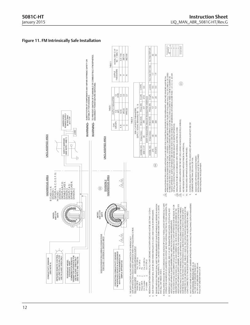
Figure 11. FM Intrinsically Safe Installation
13
Instruction Sheet 5081C-HTLIQ_MAN_ABR_5081C-HT/Rev.G January 2015
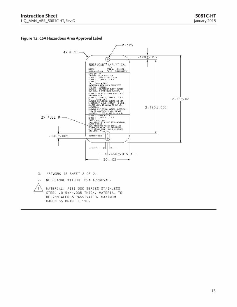
Figure 12. CSA Hazardous Area Approval label
14
5081C-HT Instruction SheetJanuary 2015 LIQ_MAN_ABR_5081C-HT/Rev.G
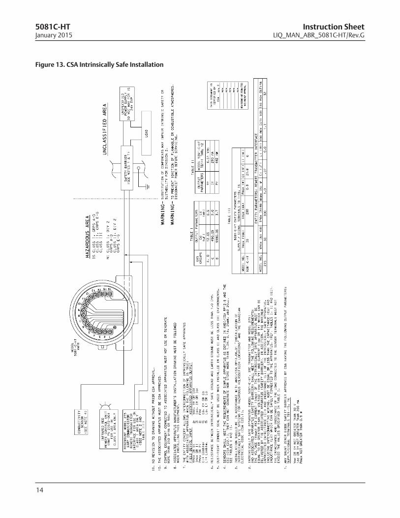
Figure 13. CSA Intrinsically Safe Installation
15
Instruction Sheet 5081C-HTLIQ_MAN_ABR_5081C-HT/Rev.G January 2015
Engineering Specifications
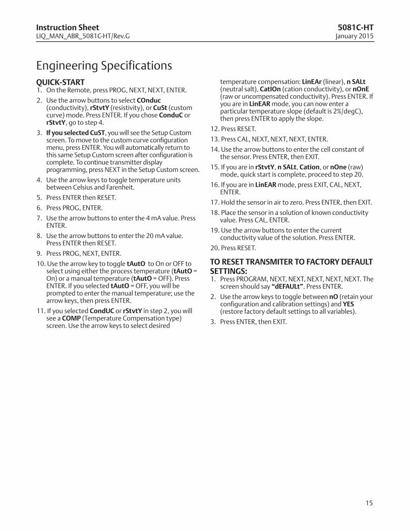
qUICK-START1. On the Remote, press PROG, NEXT, NEXT, ENTER.
2. Use the arrow buttons to select Conduc(conductivity), rStvty (resistivity), or CuSt (customcurve) mode. Press ENTER. If you chose ConduC orrStvty, go to step 4.
3. If you selected CuST, you will see the Setup Customscreen. To move to the custom curve configurationmenu, press ENTER. You will automatically return tothis same Setup Custom screen after configuration iscomplete. To continue transmitter displayprogramming, press NEXT in the Setup Custom screen.
4. Use the arrow keys to toggle temperature unitsbetween Celsius and Farenheit.
5. Press ENTER then RESET.
6. Press PROG, ENTER.
7. Use the arrow buttons to enter the 4 mA value. PressENTER.
8. Use the arrow buttons to enter the 20 mA value.Press ENTER then RESET.
9. Press PROG, NEXT, ENTER.
10. Use the arrow key to toggle tAuto to On or OFF toselect using either the process temperature (tAuto =On) or a manual temperature (tAuto = OFF). PressENTER. If you selected tAuto = OFF, you will beprompted to enter the manual temperature; use thearrow keys, then press ENTER.
11. If you selected CondUC or rStvty in step 2, you willsee a CoMp (Temperature Compensation type)screen. Use the arrow keys to select desired
temperature compensation: lineAr (linear), n SAlt(neutral salt), CatIon (cation conductivity), or none(raw or uncompensated conductivity). Press ENTER. Ifyou are in lineAR mode, you can now enter aparticular temperature slope (default is 2%/degC),then press ENTER to apply the slope.
12. Press RESET.
13. Press CAL, NEXT, NEXT, NEXT, ENTER.
14. Use the arrow buttons to enter the cell constant ofthe sensor. Press ENTER, then EXIT.
15. If you are in rStvty, n SAlt, Cation, or none (raw)mode, quick start is complete, proceed to step 20.
16. If you are in lineAR mode, press EXIT, CAL, NEXT,ENTER.
17. Hold the sensor in air to zero. Press ENTER, then EXIT.
18. Place the sensor in a solution of known conductivityvalue. Press CAL, ENTER.
19. Use the arrow buttons to enter the currentconductivity value of the solution. Press ENTER.
20. Press RESET.
To ReSeT TRANSMITeR To FACToRy deFAUlTSeTTINGS:1. Press PROGRAM, NEXT, NEXT, NEXT, NEXT, NEXT. The
screen should say “deFAUlt”. Press ENTER.
2. Use the arrow keys to toggle between no (retain yourconfiguration and calibration settings) and yeS(restore factory default settings to all variables).
3. Press ENTER, then EXIT.
LIQ_MAN_ABR_5081C-FF-FIRev. G
January 2015
Credit Cards for U.S. Purchases Only.
8
emerson process Management
2400 Barranca ParkwayIrvine, CA 92606 USATel: (949) 757-8500
Fax: (949) 474-7250
rosemountanalytical.com
© Rosemount Analytical Inc. 2015
©2015 Rosemount Analytical, Inc. All rights reserved.
The Emerson logo is a trademark and service mark of Emerson Electric Co. Brand name is a markof one of the Emerson Process Management family of companies. All other marks are the propertyof their respective owners.
The contents of this publication are presented for information purposes only, and while effort hasbeen made to ensure their accuracy, they are not to be construed as warranties or guarantees,express or implied, regarding the products or services described herein or their use or applicability.All sales are governed by our terms and conditions, which are available on request. We reserve theright to modify or improve the designs or specifications of our products at any time without notice.
facebook.com/EmersonRosemountAnalytical
AnalyticExpert.com
twitter.com/RAIhome
youtube.com/user/RosemountAnalytical