Embed Size (px)
Citation preview

Renegade Tech Works
Mitsubishi 3000gt / Stealth Electronic Strut Controller
Operations & Installation
Manual
Manual Version 1.9 / ECS M01 PCB Rev 1.1 / Firmware V1.5
All Rights Reserved
Renegade Tech Works
www.renegadetechworks.com
© 2012
www.renegadetechworks.com © 2013
2
TableofContents
Introduction ....................................................................................................... 3
TechWorks ECS Control Module Components .................................................... 5
Tech Works ECS Controller Operation Using Factory Console & ECS
Switch ............................................................................................................... 6
Tech Works ECS Controller Operation Using LED Status Lights &
Rotary Selector Switch .................................................................................... 10
Adjusting the Brightness of the LED Status Lights ........................................... 14
Installing the Tech Works ECS Controller As a Plug N Play
Replacement for the Factory OEM ECS Controller ............................................ 16
Installing the Tech Works ECS Controller as a RetroFit Into 3000gt
& Stealths that do not have the Factory ECS system or wiring ........................ 18
APPENDIX A Reference Information ................................................................ 27
www.renegadetechworks.com © 2013
3
Introduction
The Renegade Tech Works ECS controller can be used in two separate applications.
Drop in Replacement For Existing Mitsubishi OEM ECS controller
For all cars prior to 1996 that already have the Mitsu Factory ECS system, the Tech Works controller can be used as a drop in replacement for your factory OEM ECS controller.
The Tech Works controller uses the existing factory wiring harness & front panel Tour/Sport lights & ECS push button Switch. You don't need to add or wire anything. Just unplug the original and plug in the Tech Works Controller
Benefits of the TechWorks replacement controller
o The controller will provide manual control for selecting what you want the struts set to and bypass all the OEM Mitsu Sensors and any fault conditions they may be sending. You will have complete manual control over your struts.
o You have access to the MEDIUM hardness mode settings on your struts.
o You have access to the on-demand diagnostic mode using your existing ECS push button select switch and the SPORT & TOUR lights for display. For a demonstration see: Tech Works ECS Controller Diagnostic Demo
o Complete manual control operation - when you start your car - the struts will be in same state as when you turned the car off.
o you have the option adding the 4 multi-color LED status indicator lights and Rotary selector switch if desired to your factory setup.
ECS System Retrofit
The Tech Works controller can also be used in 1996, 1997, 1998 or 1999 Mitsubishi 3000gt or Stealth cars that do not have the Mitsubishi Factory OEM ECS system. It allows you to be able to retrofit the electronically controllable struts back into these later model year 3000gt cars or earlier model year cars that did not come with the ecs option.
To do the ECS Retrofit into 3000gt or Stealth you:
Remove your non-ecs struts and replace them with Mitsubishi 1995 model year standard factory OEM ECS struts & mounting hardware. You can use the OEM Springs or use after market springs such as Teins.
Install this custom controller and connect it to your vehicle +12v & Ground

www.renegadetechworks.com © 2013
4
Run a 4 wire cable from the controller to each of the 4 struts
Run 5 wires from the controller for LED display & Switch Selector to your console area and install the provided LEDs & Rotary Selector.
Now you will have manual control in the cockpit to adjust the struts to Hard, Medium or Soft , plus a detailed status & error fault display using the multi-colored LEDs plus the availibility of the on demand diagnostic mode.
www.renegadetechworks.com © 2013
5
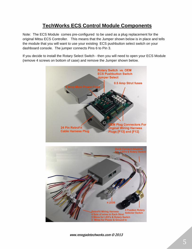
TechWorks ECS Control Module Components
Note: The ECS Module comes pre-configured to be used as a plug replacement for the original Mitsu ECS Controller. This means that the Jumper shown below is in place and tells the module that you will want to use your existing ECS pushbutton select switch on your dashboard console. The jumper connects Pins 6 to Pin 3.
If you decide to install the Rotary Select Switch - then you will need to open your ECS Module (remove 4 screws on bottom of case) and remove the Jumper shown below.

www.renegadetechworks.com © 2013
6
TechWorks ECS Controller Operation
Using Factory Console & ECS Switch
www.renegadetechworks.com © 2013
7
Normal Operation
Sport & Tour Light Indicators
In Normal Operation the Sport / Tour Light indicators will show what setting the struts are currently in as follows: SPORT Light ON = Struts in HARD mode SPORT & TOUR Light ON = Struts in MEDIUM mode TOUR Light ON = Struts in SOFT Mode
Blinking Sport Light During Normal operation.
If during normal operation the SPORT light blinks 3 times by itself intermittently - this is indicating that the controller cannot get one or more of the struts into the desired mode. Use the diagnostic mode to determine which strut(s) is having a problem.
ECS Switch Operation
In Normal Operation the ECS pushbutton switch when pressed and released will send the request to cycle the struts to the next hardness setting:
Hard -> Medium -> Soft -> Hard -> Medium -> Soft -> ...... -> .......
The Sport/Tour lights will light appropriately to indicate the requested mode.
If after pushing & releasing the ECS switch - the Sport light starts blinking intermittently 3 times - the controller is alerting you that one or more of the struts was not able to enter the desired mode.
Startup
Just after a power on condition, the controller will interrogate all four struts to see what mode they were previously left in. All struts must be in the same state (for example , all struts in HARD mode) for the initial system starting state to be a nominal (no error) starting state.
If the controller does not detect any problems - The Sport & Tour lights will light according the current state of the struts and display Hard, Medium or Soft.
If the controller does detect a problem and cannot determine what state the struts are in- the SPORT light will blink 3 times and then the Sport & Tour lights will be turned "OFF". Try pressing the ECS switch to command the struts into the next state or running the diagnostic mode to determine which strut may be having a problem.

www.renegadetechworks.com © 2013
8
Diagnostic Mode
To Enter diagnostic mode press and hold the ECS pushbutton switch until the Sport & Tour lights both turn off - then release the switch.
o Note: If both lights are already off - because of a startup failure condition - continue holding the ECS switch until the SPORT light begins blinking 1 time per second - which will indicate the diagnostic mode has started for Strut 1 - then release the switch.
The Diagnostic Routine will then start and will test each of the struts (1,2,3,4) in order performing the same test sequence for each strut.
The order of the test is:
Strut 1: Front Left Strut
Strut 2: Front Right Strut
Strut 3: Rear Left Strut
Strut 4: Rear Right Strut
The Test Sequence & Tour/Sport lights display for a given strut is as follows:
Step (1) Strut Number Being Tested: The Sport Light will blink a number of times equal to the strut number being tested. For example if the Sport light blinks 3 times - strut 3: Rear Left is about to be tested
Step (2) HARD Mode Test: controller attempts to put the strut into HARD Mode - if successful the SPORT light will turn on. If not successful, the SPORT light will not turn on and the sequence will proceed to the next step.
Step (3) MEDIUM mode test: controller attempts to put the strut into MEDIUM Mode - if successful the SPORT & TOUR lights will turn on. If not successful, the SPORT & TOUR lights will not turn on and the sequence will proceed to the next step.
Step (4) SOFT Mode test: controller attempts to put the strut into SOFT Mode - if successful the TOUR light will turn on. If not successful, the TOUR light will not turn on and the sequence will proceed to the next step.
Step (5) Strut finished testing: The SPORT and TOUR Light will blink a number of times equal to the strut that was just finished being tested. For example if the Sport light blinks 3 times - strut 3: Rear has finished being tested.
Step (6) Strut Test Results: If the strut just tested , tested OK and was able to be put into all three modes , then the SPORT & TOUR lights will light up SOLID for several seconds .

www.renegadetechworks.com © 2013
9
If the strut did NOT test ok then the SPORT & TOUR lights will not light up at all for this step. they will remain OFF.
Steps (5) & (6) will repeat 3 more times - to display the results for the strut just tested
Step (7) Next Strut: testing will now proceed to the next strut and start over with Step(1)
To Exit Diagnostic Mode - press and hold the ECS switch briefly to exit the testing cycle. The press will only be detected when the lights are not blinking. You can also turn off the ignition.
www.renegadetechworks.com © 2013
10
Tech Works ECS Controller Operation
Using LED Status Lights & Rotary Selector Switch
www.renegadetechworks.com © 2013
11
Normal Operation
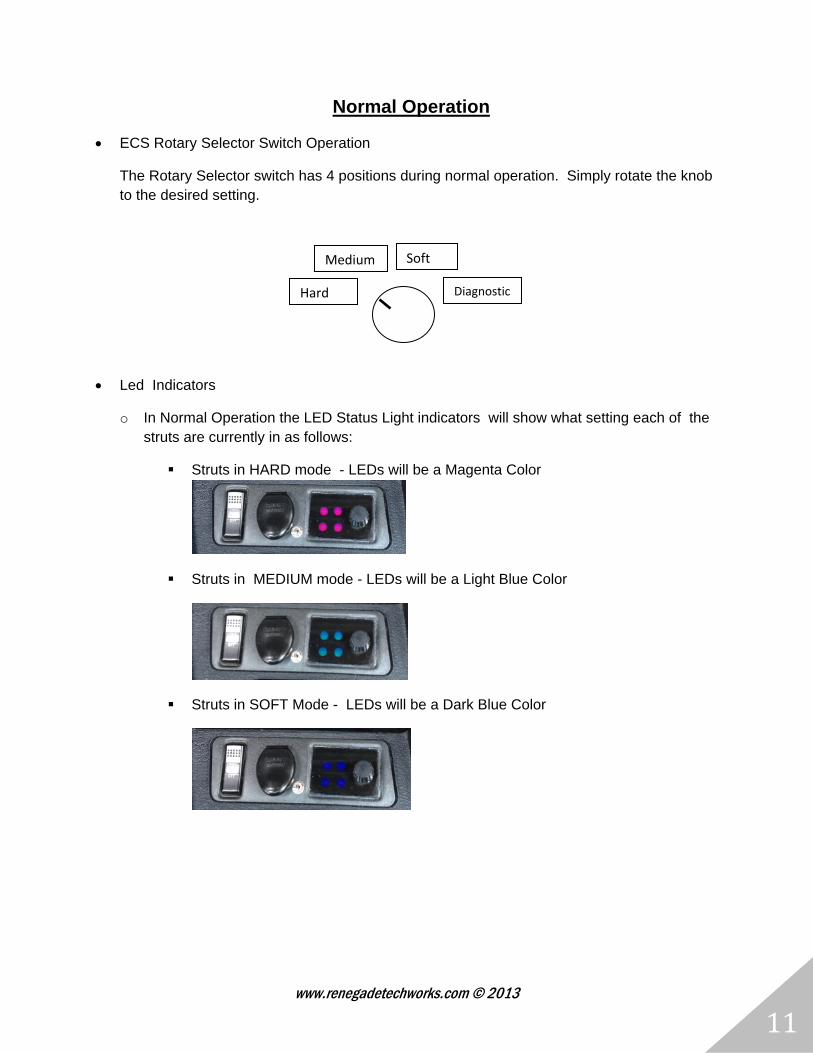
ECS Rotary Selector Switch Operation
The Rotary Selector switch has 4 positions during normal operation. Simply rotate the knob to the desired setting.
Led Indicators
o In Normal Operation the LED Status Light indicators will show what setting each of the struts are currently in as follows:
Struts in HARD mode - LEDs will be a Magenta Color
Struts in MEDIUM mode - LEDs will be a Light Blue Color
Struts in SOFT Mode - LEDs will be a Dark Blue Color
Medium
Hard
Soft
Diagnostic
www.renegadetechworks.com © 2013
12
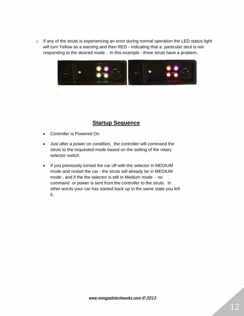
o If any of the struts is experiencing an error during normal operation the LED status light will turn Yellow as a warning and then RED - indicating that a particular strut is not responding to the desired mode . In this example - three struts have a problem.
.
Startup Sequence
Controller is Powered On
Just after a power on condition, the controller will command the struts to the requested mode based on the setting of the rotary selector switch.
If you previously turned the car off with the selector in MEDIUM mode and restart the car - the struts will already be in MEDIUM mode , and if the the selector is still in Medium mode - no command or power is sent from the controller to the struts. In other words your car has started back up in the same state you left it.
www.renegadetechworks.com © 2013
13
Diagnostic Mode Using LED Status Lights & Rotary Switch
To Enter diagnostic rotate the selector switch to position 4 - the rightmost clockwise position.
The Diagnostic Routine will then start and will test each of the struts in order performing the same test sequence for each strut. The order of the test is:
Strut 1:Front Left ->Strut 2: Front Right ->Strut 3: Rear Left -> Strut 4: Rear Right
The Test Sequence & LED lights display for a given strut is as follows:
Step (0) As soon as you enter diagnostic mode - all the LED status lights will be turned off
Step (1) Strut being Tested: A white LED Status light corresponding to the strut being tested will be turned on .
Step (2) HARD Mode Test: controller attempts to put the strut into HARD Mode - if successful the LED Status light will turn on with the HARD mode color (Magenta). If not successful, the LED status light will turn Yellow as warning and then RED if the strut fails the test. If the strut fails the Hard mode test, the test sequence stops for this strut and proceeds to step (5)
Step (3) MEDIUM mode test: controller attempts to put the strut into MEDIUM Mode - if successful the LED Status light will turn on with the MEDIUM mode color (Light Blue). If not successful, the LED status light will turn Yellow as warning and then RED if the strut fails. If the strut fails this test, the test sequence stops for this strut and proceeds to step (5)
Step (4) SOFT Mode test: controller attempts to put the strut into SOFT Mode - if successful the LED Status light will turn on with the SOFT mode color (Blue). If not successful, the LED status light will turn Yellow as warning and then RED if the strut fails.
Step (5) Strut finished testing & Strut Test Results: The LED Status light for the strut that was tested will turn GREEN if the strut passed the test and RED if the strut failed.
Step (6) Next Strut: testing will now proceed to the next strut and start over with Step(1)
To Exit Diagnostic Mode - simple turn the rotary selector switch to any position other than Diagnostic mode - position 4. You can also turn off the ignition.

www.renegadetechworks.com © 2013
14
Adjusting the Brightness of the LED Status Lights

www.renegadetechworks.com © 2013
15
The brightness of the LED status display lights can be adjusted during the initial power on sequence of the controller. To adjust the brightness levels do the following:
Step (1) Before you turn on the ignition to the car
a. if using the Rotary Selector Switch - Turn the selector switch to diagnostic mode.
b. if using the factory pushbutton ECS switch - Press and HOLD the ECS switch.
Step (2) Start the Car
Step (3) The LED Status lights will briefly turn WHITE and then once DIAGNOSTIC mode is detected the four status light will turn BRIGHT RED, MAGENTA, LIGHT BLUE & BLUE. This indicates the controller has entered Dimness control mode.
Step (4) You will have 5 seconds to select the brightness level desired by doing one of the following:
a. If using the Rotary Switch - turn the selector to the desired brightness level - the lights will dim or brighten - depending upon what position you put the selector in. The Diagnostic position 4 is the brightest setting. The Hard mode position 1 is the dimmest setting.
b. if using factory pushbutton ECS switch - Pressing the switch will cycle the LED lights to the next brightness level.
Step(5) After 5 seconds the currently selected brightness level will be used and All four LED lights will be set back to WHITE - to indicate that the brightness setting mode is completed.
NOTE: if you are using the rotary switch - you should now reposition the selector to the desired strut hardness setting : Hard, Medium, or Soft. If you leave the switch in the Diagnostic mode - the diagnostic routine will begin executing once controller normal operations resume - which occurs immediately after the 4 WHITE LEDS lights go out.

www.renegadetechworks.com © 2013
16
Installing the TechWorks ECS Controller
As a Plug N Play Replacement for the Factory OEM ECS Controller
www.renegadetechworks.com © 2013
17
To Replace your Factory OEM ECS controller with the TechWorks ECS controller
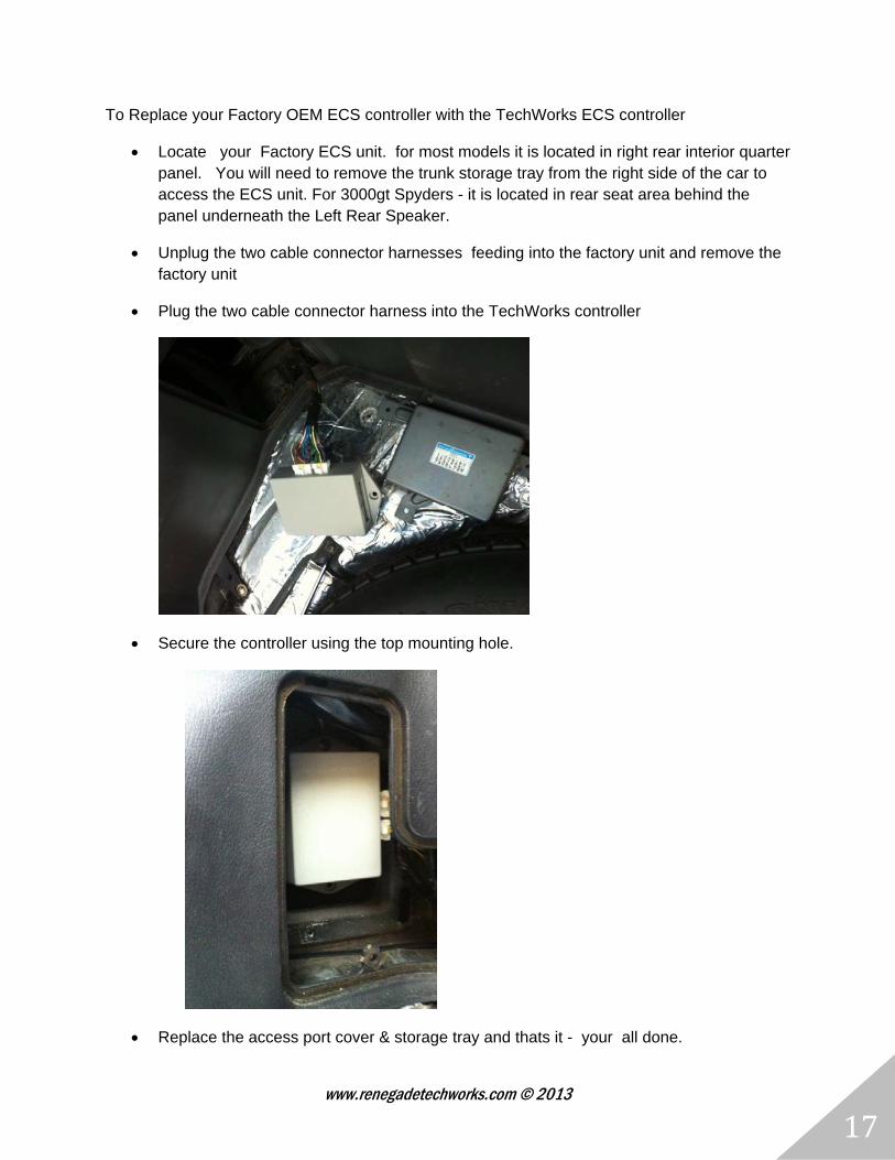
Locate your Factory ECS unit. for most models it is located in right rear interior quarter panel. You will need to remove the trunk storage tray from the right side of the car to access the ECS unit. For 3000gt Spyders - it is located in rear seat area behind the panel underneath the Left Rear Speaker.
Unplug the two cable connector harnesses feeding into the factory unit and remove the factory unit
Plug the two cable connector harness into the TechWorks controller
Secure the controller using the top mounting hole.
Replace the access port cover & storage tray and thats it - your all done.

www.renegadetechworks.com © 2013
18
Installing the Tech Works ECS Controller
RetroFit Into 3000gt & Stealths that do not have the Factory ECS system or wiring
www.renegadetechworks.com © 2013
19
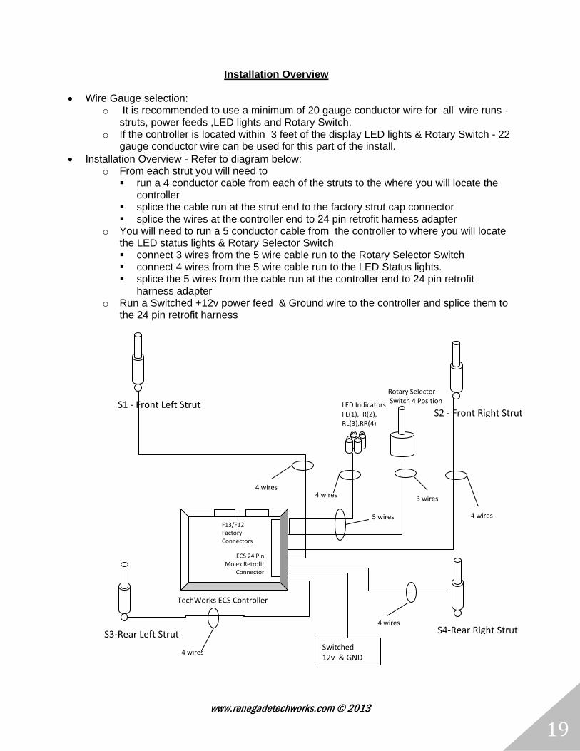
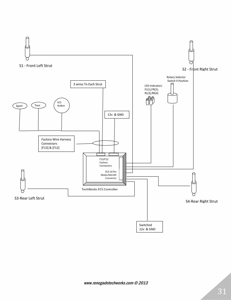
Installation Overview
Wire Gauge selection: o It is recommended to use a minimum of 20 gauge conductor wire for all wire runs -
struts, power feeds ,LED lights and Rotary Switch. o If the controller is located within 3 feet of the display LED lights & Rotary Switch - 22
gauge conductor wire can be used for this part of the install. Installation Overview - Refer to diagram below:
o From each strut you will need to run a 4 conductor cable from each of the struts to the where you will locate the
controller splice the cable run at the strut end to the factory strut cap connector splice the wires at the controller end to 24 pin retrofit harness adapter
o You will need to run a 5 conductor cable from the controller to where you will locate the LED status lights & Rotary Selector Switch connect 3 wires from the 5 wire cable run to the Rotary Selector Switch connect 4 wires from the 5 wire cable run to the LED Status lights. splice the 5 wires from the cable run at the controller end to 24 pin retrofit
harness adapter o Run a Switched +12v power feed & Ground wire to the controller and splice them to
the 24 pin retrofit harness
5 wires
4 wires
4 wires
S2 ‐ Front Right StrutS1 ‐ Front Left Strut
S4‐Rear Right StrutS3‐Rear Left Strut
Rotary Selector Switch 4 Position
LED IndicatorsFL(1),FR(2), RL(3),RR(4)
F13/F12 Factory Connectors
ECS 24 Pin Molex Retrofit
Connector
Switched 12v & GND
TechWorks ECS Controller
4 wires
4 wires
3 wires
4 wires
www.renegadetechworks.com © 2013
20
Installation Steps
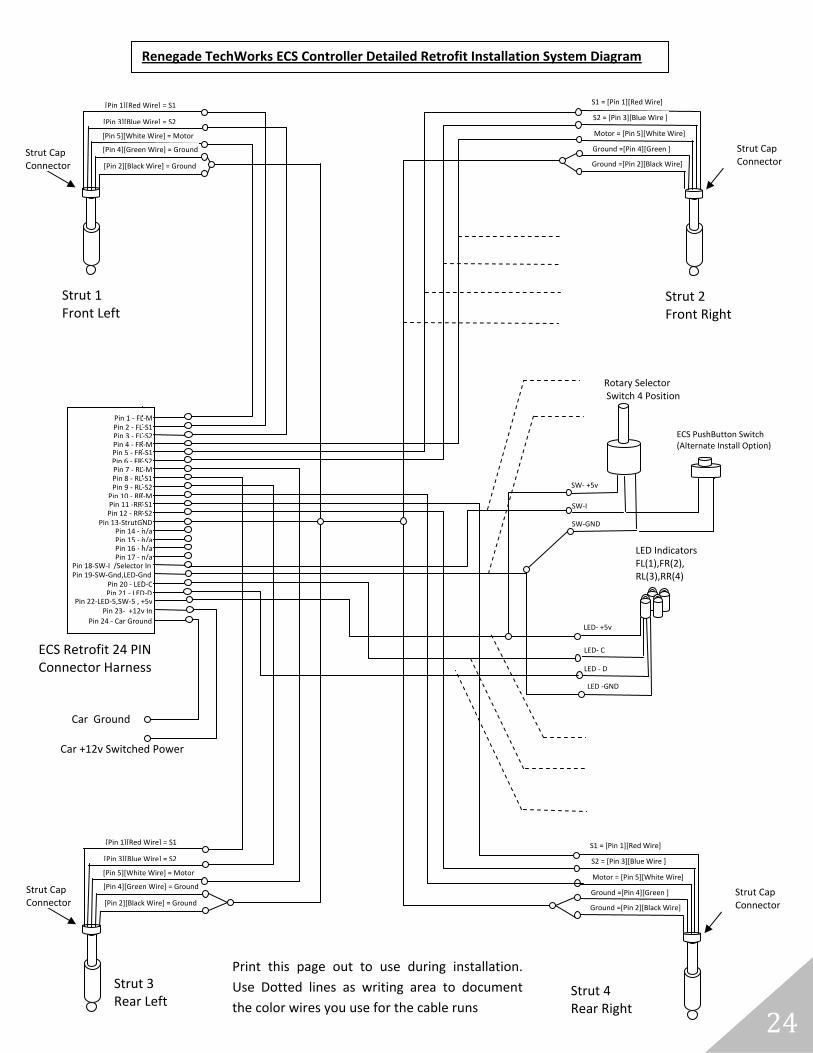
At the end of this section is a detailed installation system diagram that shows what needs to get connected. It is how your system should be connected when done. This diagram has areas on it for you to write down what color wires you are using to complete the installation. Print it out and use it to document your installation.
Step (1) Remove your non-ecs struts and replace them with Mitsubishi 1995 model year standard factory OEM ECS struts & mounting hardware. You can use the OEM ECS Springs or use after market springs such as Teins.
Step (1b) As part of the retrofit install you should have ordered 4 strut cap connector harnesses that plug into the top of each strut. Cut the ends farthest away from the strut cap connector off - you will need to splice the wires coming from these strut cap connectors to the 4 conductor cables that you run to the controller.
Step (2) Pick a suitable mounting location for the controller.
o Candidate locations are - inside the center console or in the right rear quarter panel where the factory controller would normally be installed.
o Whatever location is picked , will require the running of four - 4 conductor cables to each of the struts from the controller - so keep this in mind.
Step (3) Providing Power to the Controller: Locate and run a Switched +12v & Ground set of wires to where you will be installing the controller.
Step (3a) splice the vehicle switched power wire to the wire labeled "+12v P 23" of the controller wiring harness

www.renegadetechworks.com © 2013
21
Step (3b) splice the vehicle ground wire to the wire labeled "GND P24" of the controller wiring harness
Step (4) Connecting the LED Display & Selector Switch: Run 5 wires from the controller for LED display & Switch Selector to your console area.
Step (4a) On the controller side ,Splice the 5 wires to the following 5 controller harness wires labeled:
o SW-I P18
o SW-GND LED-GND P19
o LED-C P20,
o LED-D P21
o SW-5 LED-5 P22
Step (4b) DO This Step only if Using the Rotary Selector Switch & LEDS
NOTE: The internal jumper inside the ECS Control unit must be Removed to tell the system to use the rotary switch.
o On the console side , using the 4 wire wiring harness pigtail attached to the LED lights & the 3 wire harness pigtail for Selector Switch , splice the wires as follows to 5 wire cable that now connects to the controller wiring harness.
o LED Pigtail wire labeled " LED-GND P1" & the Selector Switch Pigtail wire labeled "SW-GND P1" connects to the 5 wire feed corresponding to "LED-GND SW-GND P19 from the Controller side.
o LED Pigtail wire labeled " LED-5 P2" & the Selector Switch Pigtail wire labeled "SW-5 P2" connects to the 5 wire feed corresponding to "LED-5 SW-5 P19 from the Controller side
o LED Pigtail wire labeled " LED-D P3" connects to the 5 wire feed corresponding to "LED-D P21 from the Controller side.
o LED Pigtail wire labeled " LED-C P4" connects to the 5 wire feed corresponding to "LED-C P20 from the Controller side.
o Rotary Selector Switch Pigtail wire labeled " SW-I P3" connects to the 5 wire feed corresponding to "SW-I P18 from the Controller side.
www.renegadetechworks.com © 2013
22
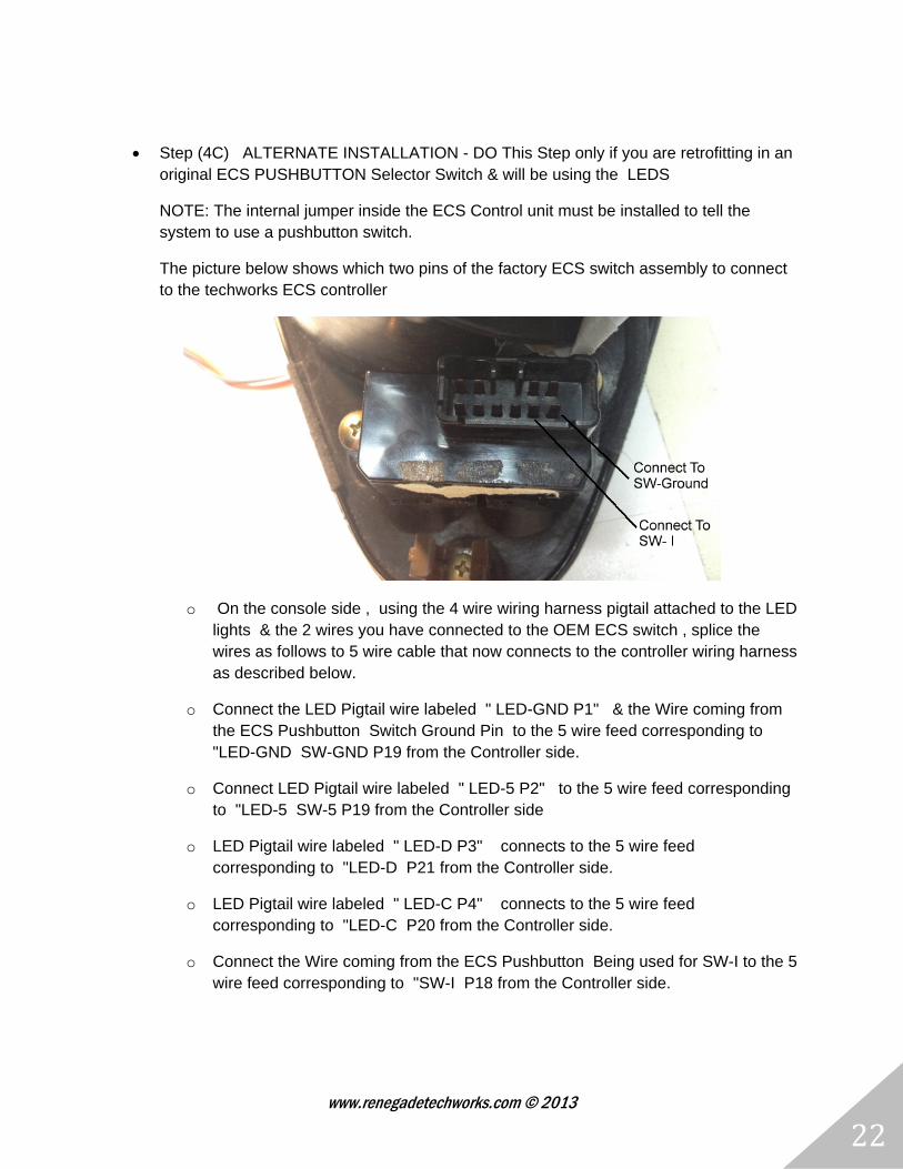
Step (4C) ALTERNATE INSTALLATION - DO This Step only if you are retrofitting in an original ECS PUSHBUTTON Selector Switch & will be using the LEDS
NOTE: The internal jumper inside the ECS Control unit must be installed to tell the system to use a pushbutton switch.
The picture below shows which two pins of the factory ECS switch assembly to connect to the techworks ECS controller
o On the console side , using the 4 wire wiring harness pigtail attached to the LED lights & the 2 wires you have connected to the OEM ECS switch , splice the wires as follows to 5 wire cable that now connects to the controller wiring harness as described below.
o Connect the LED Pigtail wire labeled " LED-GND P1" & the Wire coming from the ECS Pushbutton Switch Ground Pin to the 5 wire feed corresponding to "LED-GND SW-GND P19 from the Controller side.
o Connect LED Pigtail wire labeled " LED-5 P2" to the 5 wire feed corresponding to "LED-5 SW-5 P19 from the Controller side
o LED Pigtail wire labeled " LED-D P3" connects to the 5 wire feed corresponding to "LED-D P21 from the Controller side.
o LED Pigtail wire labeled " LED-C P4" connects to the 5 wire feed corresponding to "LED-C P20 from the Controller side.
o Connect the Wire coming from the ECS Pushbutton Being used for SW-I to the 5 wire feed corresponding to "SW-I P18 from the Controller side.

www.renegadetechworks.com © 2013
23
Step (5) Run a 4 wire conductor cable to each of the four struts from the controller location.
Step (5a) at each of the struts using the strut cap connector harness prepared in Step (1b) above splice the 5 wires from the connector harness to the 4 wire cable as follows:
o From the strut cap connector harness connect the GREEN & BLACK ground wires to one of the 4 wires. Make a Note which of the 4 wires you are using as ground.
o From the strut cap connector harness connect the White Motor Wire to one of the 4 wires. Make a Note which of the 4 wires you are using as the Motor Wire.
o From the strut cap connector harness connect the RED S1 Signal Wire to one of the 4 wires. Make a Note which of the 4 wires you are using as the S1 Wire.
o From the strut cap connector harness connect the BLUE S2 Signal Wire to one of the 4 wires. Make a Note which of the 4 wires you are using as the S2 Wire.
o Repeat these connections for the other 3 struts.
Step (6) Connect each of the 4 strut cable feeds from Step (5) to the ECS controller side wiring harness. Using the Front LEFT strut as an example:
o Connect the wire coming from the Front Left Strut Cap Harness White Motor wire to the controller side connector harness wire labeled "FL-M P1".
o Connect the wire coming from the Front Left Strut Cap Harness RED S1 Signal wire to the controller side connector harness wire labeled "FL-S1 P2".
o Connect the wire coming from the Front Left Strut Cap Harness BLUE S2 Signal wire to the controller side connector harness wire labeled "FL-S2 P3".
o Connect the wire coming from the Front Left Strut Cap Harness Ground wires (Green & Black ) to the controller side connector harness wire labeled "S-GND P13".
NOTE: the controller side P13 Ground wire is a common ground wire used by all four strut grounds. So you will want to splice the 4 common ground wires from all four struts - all at once
Step (6a) Repeat Step 6 for the other 3 struts.
o Front Right Strut connects to controller harness Pins 4,5,6 & 13.
o Rear Left Strut connects to controller harness Pins 7,8,9 & 13.
o Rear Right Strut connects to controller harness Pins 10,11,12 & 13.
www.renegadetechworks.com © 2013
24
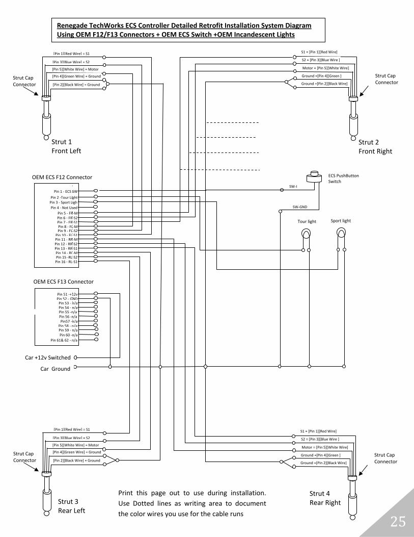
Strut CapConnector
Strut CapConnector
Car +12v Switched Power
Strut 1 Front Left
Strut Cap Connector
[Pin 1][Red Wire] = S1
[Pin 3][Blue Wire] = S2
[Pin 5][White Wire] = Motor
[Pin 4][Green Wire] = Ground
[Pin 2][Black Wire] = Ground
Strut 2 Front Right
S1 = [Pin 1][Red Wire]
S2 = [Pin 3][Blue Wire ]
Motor = [Pin 5][White Wire]
Ground =[Pin 4][Green ]
Ground =[Pin 2][Black Wire]
Strut 4 Rear Right
S1 = [Pin 1][Red Wire]
S2 = [Pin 3][Blue Wire ]
Motor = [Pin 5][White Wire]
Ground =[Pin 4][Green ]
Ground =[Pin 2][Black Wire]
Strut 3 Rear Left
Strut Cap Connector
[Pin 1][Red Wire] = S1
[Pin 3][Blue Wire] = S2
[Pin 5][White Wire] = Motor
[Pin 4][Green Wire] = Ground
[Pin 2][Black Wire] = Ground
ECS Retrofit 24 PIN Connector Harness
Pin 1 ‐ FL‐MPin 2 ‐ FL‐S1Pin 3 ‐ FL‐S2Pin 4 ‐ FR‐MPin 5 ‐ FR‐S1Pin 6 ‐ FR‐S2Pin 7 ‐ RL‐MPin 8 ‐ RL‐S1Pin 9 ‐ RL‐S2
Pin 10 ‐ RR‐MPin 11 ‐RR‐S1Pin 12 ‐ RR‐S2
Pin 13‐StrutGNDPin 14 ‐ n/aPin 15 ‐ n/aPin 16 ‐ n/aPin 17 ‐ n/a
Pin 20 ‐ LED‐CPin 21 ‐ LED‐D
Pin 19‐SW‐Gnd,LED‐Gnd
Pin 22‐LED‐5,SW‐5 , +5vPin 23‐ +12v In
Pin 24 ‐ Car Ground
Pin 18‐SW‐I /Selector In
SW‐I
SW‐ +5v
SW‐GND
Rotary Selector Switch 4 Position
Car Ground
LED‐ +5v
LED ‐GND
LED‐ C
LED ‐ D
LED IndicatorsFL(1),FR(2), RL(3),RR(4)
Print this page out to use during installation.
Use Dotted lines as writing area to document
the color wires you use for the cable runs
ECS PushButton Switch (Alternate Install Option)
Renegade TechWorks ECS Controller Detailed Retrofit Installation System Diagram
www.renegadetechworks.com © 2013
25
Strut Cap Connector
[Pin 1][Red Wire] = S1 S1 = [Pin 1][Red Wire]
Print this page out to use during installation.
Use Dotted lines as writing area to document
the color wires you use for the cable runs
Strut Cap Connector
Strut CapConnector
Strut CapConnector
Car +12v Switched
Strut 1 Front Left
[Pin 3][Blue Wire] = S2
[Pin 5][White Wire] = Motor
[Pin 4][Green Wire] = Ground
[Pin 2][Black Wire] = Ground
Strut 2 Front Right
S2 = [Pin 3][Blue Wire ]
Motor = [Pin 5][White Wire]
Ground =[Pin 4][Green ]
Ground =[Pin 2][Black Wire]
Strut 4 Rear Right
S1 = [Pin 1][Red Wire]
S2 = [Pin 3][Blue Wire ]
Motor = [Pin 5][White Wire]
Ground =[Pin 4][Green ]
Ground =[Pin 2][Black Wire]
Strut 3 Rear Left
[Pin 1][Red Wire] = S1
[Pin 3][Blue Wire] = S2
[Pin 5][White Wire] = Motor
[Pin 4][Green Wire] = Ground
[Pin 2][Black Wire] = Ground
Pin 5 ‐ FR‐MPin 6 ‐ FR‐S2Pin 7 ‐ FR‐S1Pin 8 ‐ FL‐MPin 9 ‐ FL‐S2
Pin 10 ‐ FL‐S1Pin 11 ‐ RR‐MPin 12 ‐ RR‐S2Pin 13 ‐ RR‐S1Pin 14 ‐ RL‐MPin 15 ‐RL‐S2Pin 16 ‐ RL‐S1
Pin 51 ‐+12vPin 52 ‐ GNDPin 53 ‐ n/aPin 54 ‐ n/a
Pin57 ‐n/aPin 58 ‐ n/a
Pin 56 ‐n/a
Pin 59 ‐ n/aPin 60 ‐n/a
Pin 61& 62 ‐ n/a
Pin 55 ‐n/a
SW‐GND
Car Ground
ECS PushButton Switch
Pin 1 ‐ ECS SW
Pin 2 ‐Tour LightPin 3 ‐ Sport Ligh
Pin 4 ‐ Not Used
SW‐I
Tour light Sport light
OEM ECS F12 Connector
OEM ECS F13 Connector
Renegade TechWorks ECS Controller Detailed Retrofit Installation System Diagram Using OEM F12/F13 Connectors + OEM ECS Switch +OEM Incandescent Lights

www.renegadetechworks.com © 2013
26
APPENDIX A
Reference Information
www.renegadetechworks.com © 2013
27
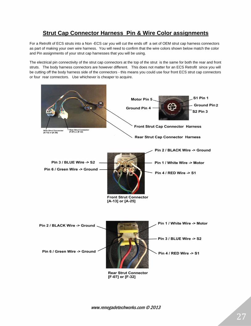
Strut Cap Connector Harness Pin & Wire Color assignments
For a Retrofit of ECS struts into a Non -ECS car you will cut the ends off a set of OEM strut cap harness connectors as part of making your own wire harness. You will need to confirm that the wire colors shown below match the color and Pin assignments of your strut cap harnesses that you will be using.
The electrical pin connectivity of the strut cap connectors at the top of the strut is the same for both the rear and front struts. The body harness connectors are however different. This does not matter for an ECS Retrofit since you will be cutting off the body harness side of the connectors - this means you could use four front ECS strut cap connectors or four rear connectors. Use whichever is cheaper to acquire.
www.renegadetechworks.com © 2013
28
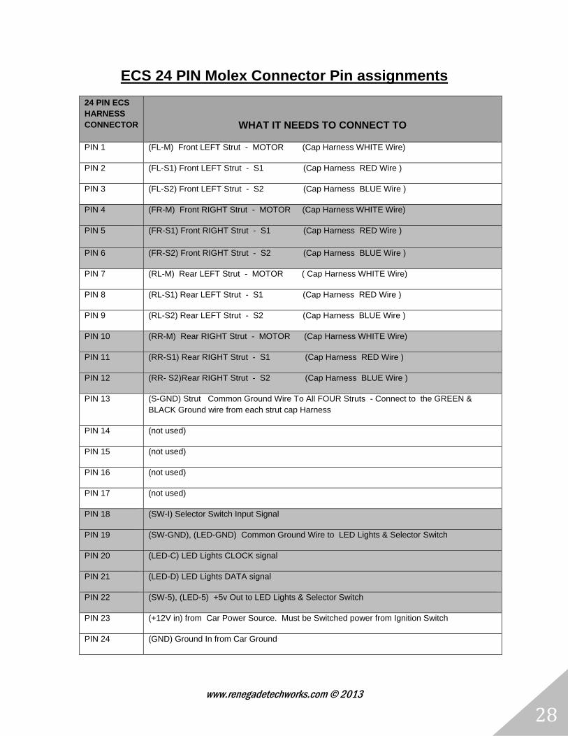
ECS 24 PIN Molex Connector Pin assignments
24 PIN ECS HARNESS CONNECTOR
WHAT IT NEEDS TO CONNECT TO
PIN 1 (FL-M) Front LEFT Strut - MOTOR (Cap Harness WHITE Wire)
PIN 2 (FL-S1) Front LEFT Strut - S1 (Cap Harness RED Wire )
PIN 3 (FL-S2) Front LEFT Strut - S2 (Cap Harness BLUE Wire )
PIN 4 (FR-M) Front RIGHT Strut - MOTOR (Cap Harness WHITE Wire)
PIN 5 (FR-S1) Front RIGHT Strut - S1 (Cap Harness RED Wire )
PIN 6 (FR-S2) Front RIGHT Strut - S2 (Cap Harness BLUE Wire )
PIN 7 (RL-M) Rear LEFT Strut - MOTOR ( Cap Harness WHITE Wire)
PIN 8 (RL-S1) Rear LEFT Strut - S1 (Cap Harness RED Wire )
PIN 9 (RL-S2) Rear LEFT Strut - S2 (Cap Harness BLUE Wire )
PIN 10 (RR-M) Rear RIGHT Strut - MOTOR (Cap Harness WHITE Wire)
PIN 11 (RR-S1) Rear RIGHT Strut - S1 (Cap Harness RED Wire )
PIN 12 (RR- S2)Rear RIGHT Strut - S2 (Cap Harness BLUE Wire )
PIN 13 (S-GND) Strut Common Ground Wire To All FOUR Struts - Connect to the GREEN & BLACK Ground wire from each strut cap Harness
PIN 14 (not used)
PIN 15 (not used)
PIN 16 (not used)
PIN 17 (not used)
PIN 18 (SW-I) Selector Switch Input Signal
PIN 19 (SW-GND), (LED-GND) Common Ground Wire to LED Lights & Selector Switch
PIN 20 (LED-C) LED Lights CLOCK signal
PIN 21 (LED-D) LED Lights DATA signal
PIN 22 (SW-5), (LED-5) +5v Out to LED Lights & Selector Switch
PIN 23 (+12V in) from Car Power Source. Must be Switched power from Ignition Switch
PIN 24 (GND) Ground In from Car Ground
www.renegadetechworks.com © 2013
29
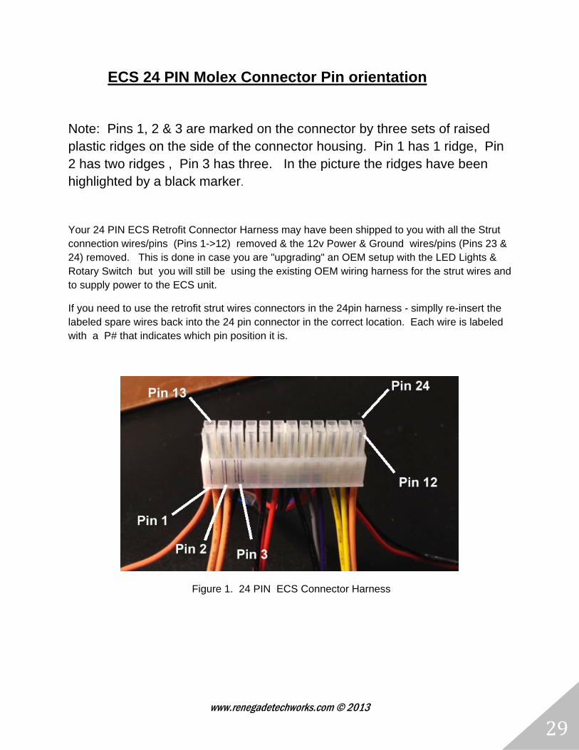
ECS 24 PIN Molex Connector Pin orientation
Note: Pins 1, 2 & 3 are marked on the connector by three sets of raised plastic ridges on the side of the connector housing. Pin 1 has 1 ridge, Pin 2 has two ridges , Pin 3 has three. In the picture the ridges have been highlighted by a black marker.
Your 24 PIN ECS Retrofit Connector Harness may have been shipped to you with all the Strut connection wires/pins (Pins 1->12) removed & the 12v Power & Ground wires/pins (Pins 23 & 24) removed. This is done in case you are "upgrading" an OEM setup with the LED Lights & Rotary Switch but you will still be using the existing OEM wiring harness for the strut wires and to supply power to the ECS unit.
If you need to use the retrofit strut wires connectors in the 24pin harness - simplly re-insert the labeled spare wires back into the 24 pin connector in the correct location. Each wire is labeled with a P# that indicates which pin position it is.
Figure 1. 24 PIN ECS Connector Harness
www.renegadetechworks.com © 2013
30
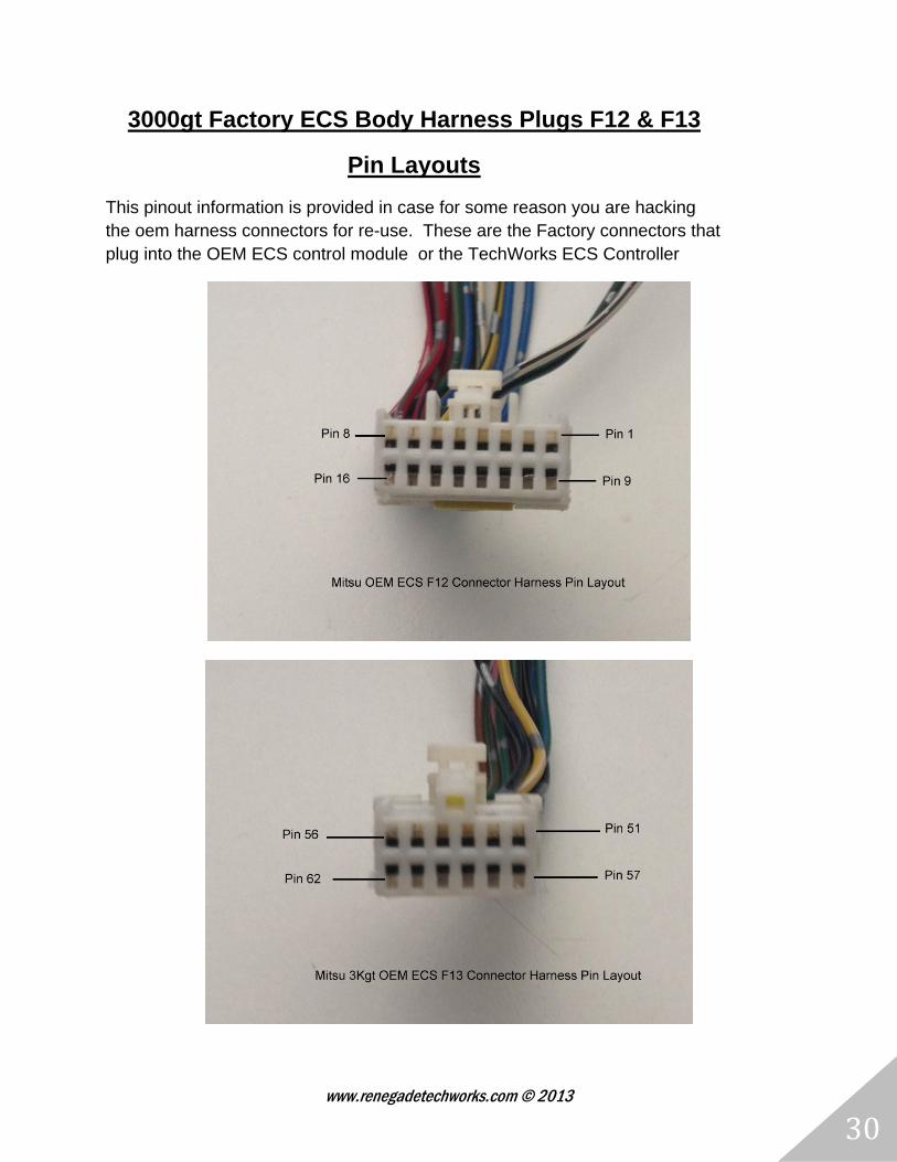
3000gt Factory ECS Body Harness Plugs F12 & F13
Pin Layouts
This pinout information is provided in case for some reason you are hacking the oem harness connectors for re-use. These are the Factory connectors that plug into the OEM ECS control module or the TechWorks ECS Controller
www.renegadetechworks.com © 2013
31
S2 ‐ Front Right StrutS1 ‐ Front Left Strut
S4‐Rear Right StrutS3‐Rear Left Strut
Rotary Selector Switch 4 Position
LED Indicators FL(1),FR(2), RL(3),RR(4)
Sport Tour ECS Button
Factory Wire Harness Connectors [F13] & [F12]
3 wires To Each Strut
12v & GND
F13/F12 Factory Connectors
ECS 24 Pin Molex Retrofit
Connector
Switched 12v & GND
TechWorks ECS Controller