Embed Size (px)
Citation preview
Renewable and Sustainable Energy Reviews 16 (2012) 4175– 4189
Contents lists available at SciVerse ScienceDirect
Renewable and Sustainable Energy Reviews
j ourna l h o mepage: www.elsev ier .com/ locate / rser
A technical, economical and market review of organic Rankine cycles for theconversion of lowgrade heat for power generation
Fredy Vélez a,∗, José J. Segoviab, M. Carmen Martínb, Gregorio Antolín a, Farid Chejne c, Ana Quijano a
a CARTIF Centro Tecnológico, Parque Tecnológico de Boecillo, Parcela 205, 47151 Valladolid, Spainb Departamento de Ingeniería Energética y Fluidomecanica, Universidad de Valladolid, Paseo del cauce s/n, Valladolid, Spainc Grupo de Termodinámica Aplicada y Energías Alternativas TAYEA, Facultad de Minas, Universidad Nacional de Colombia, Carr. 80 No. 65–223, Medellín, Colombia
a r t i c l e i n f o
Article history:
Received 1 July 2011
Accepted 7 March 2012
Available online 27 April 2012
Keywords:
Biomass
Solar energy
Geothermal
Waste heat
Cogeneration and energy efficiency
a b s t r a c t
This paper presents an overview of the technical and economic aspects, as well as the market evolution
of the Organic Rankine Cycle (ORC). This is an unconventional but very promising technology for the
conversion of thermal energy, at low and medium temperatures, into electrical and/or mechanical energy
on a small scale. As it makes a greater and/or more intensive use of its energy source, this technology
could facilitate an electricity supply to unconnected areas, the selfproduction of energy, the desalination
of seawater for human consumption, or even to increase the energy efficiency in the industrial sector
respecting the environment. A look at the scientific publications on this topic shows an open research
line, namely the selection of a suitable working fluid for these systems, since there is as yet none that
provides all aspects that must be taken into account in ORCs. Furthermore, a description and an analysis
of the applications of the proposed technology is carried out, specifying the main providers, which at the
present time is limited mainly to the range 0.2–2 MWe with a cost of around 1 and 4 × 10³ D /kWe. Lower
powers are in precommercial status.
© 2012 Elsevier Ltd. All rights reserved.
Contents
1. Introduction . . . . . . . . . . . . . . . . . . . . . . . . . . . . . . . . . . . . . . . . . . . . . . . . . . . . . . . . . . . . . . . . . . . . . . . . . . . . . . . . . . . . . . . . . . . . . . . . . . . . . . . . . . . . . . . . . . . . . . . . . . . . . . . . . . . . . . . . . . 4176
2. Operation principle . . . . . . . . . . . . . . . . . . . . . . . . . . . . . . . . . . . . . . . . . . . . . . . . . . . . . . . . . . . . . . . . . . . . . . . . . . . . . . . . . . . . . . . . . . . . . . . . . . . . . . . . . . . . . . . . . . . . . . . . . . . . . . . . . . 4176
3. Selection of the working fluid . . . . . . . . . . . . . . . . . . . . . . . . . . . . . . . . . . . . . . . . . . . . . . . . . . . . . . . . . . . . . . . . . . . . . . . . . . . . . . . . . . . . . . . . . . . . . . . . . . . . . . . . . . . . . . . . . . . . . . . 4176
4. Applications of the ORC technology according to the energy source . . . . . . . . . . . . . . . . . . . . . . . . . . . . . . . . . . . . . . . . . . . . . . . . . . . . . . . . . . . . . . . . . . . . . . . . . . . . . . . 4178
4.1. Solar power applications . . . . . . . . . . . . . . . . . . . . . . . . . . . . . . . . . . . . . . . . . . . . . . . . . . . . . . . . . . . . . . . . . . . . . . . . . . . . . . . . . . . . . . . . . . . . . . . . . . . . . . . . . . . . . . . . . . . . . 4178
4.1.1. Thermoelectric plants . . . . . . . . . . . . . . . . . . . . . . . . . . . . . . . . . . . . . . . . . . . . . . . . . . . . . . . . . . . . . . . . . . . . . . . . . . . . . . . . . . . . . . . . . . . . . . . . . . . . . . . . . . . . . . 4179
4.1.2. Water desalination . . . . . . . . . . . . . . . . . . . . . . . . . . . . . . . . . . . . . . . . . . . . . . . . . . . . . . . . . . . . . . . . . . . . . . . . . . . . . . . . . . . . . . . . . . . . . . . . . . . . . . . . . . . . . . . . . 4179
4.2. Biomass applications . . . . . . . . . . . . . . . . . . . . . . . . . . . . . . . . . . . . . . . . . . . . . . . . . . . . . . . . . . . . . . . . . . . . . . . . . . . . . . . . . . . . . . . . . . . . . . . . . . . . . . . . . . . . . . . . . . . . . . . . . 4180
4.2.1. Biomass combustion . . . . . . . . . . . . . . . . . . . . . . . . . . . . . . . . . . . . . . . . . . . . . . . . . . . . . . . . . . . . . . . . . . . . . . . . . . . . . . . . . . . . . . . . . . . . . . . . . . . . . . . . . . . . . . . . 4180
4.2.2. Gasification . . . . . . . . . . . . . . . . . . . . . . . . . . . . . . . . . . . . . . . . . . . . . . . . . . . . . . . . . . . . . . . . . . . . . . . . . . . . . . . . . . . . . . . . . . . . . . . . . . . . . . . . . . . . . . . . . . . . . . . . . 4181
4.2.3. Biogas . . . . . . . . . . . . . . . . . . . . . . . . . . . . . . . . . . . . . . . . . . . . . . . . . . . . . . . . . . . . . . . . . . . . . . . . . . . . . . . . . . . . . . . . . . . . . . . . . . . . . . . . . . . . . . . . . . . . . . . . . . . . . . . 4182
4.3. Geothermal energy applications . . . . . . . . . . . . . . . . . . . . . . . . . . . . . . . . . . . . . . . . . . . . . . . . . . . . . . . . . . . . . . . . . . . . . . . . . . . . . . . . . . . . . . . . . . . . . . . . . . . . . . . . . . . . . 4182
4.4. Applications with waste heat of processes . . . . . . . . . . . . . . . . . . . . . . . . . . . . . . . . . . . . . . . . . . . . . . . . . . . . . . . . . . . . . . . . . . . . . . . . . . . . . . . . . . . . . . . . . . . . . . . . . . 4183
4.5. Combined cycle applications . . . . . . . . . . . . . . . . . . . . . . . . . . . . . . . . . . . . . . . . . . . . . . . . . . . . . . . . . . . . . . . . . . . . . . . . . . . . . . . . . . . . . . . . . . . . . . . . . . . . . . . . . . . . . . . . . 4184
4.5.1. Gas turbines . . . . . . . . . . . . . . . . . . . . . . . . . . . . . . . . . . . . . . . . . . . . . . . . . . . . . . . . . . . . . . . . . . . . . . . . . . . . . . . . . . . . . . . . . . . . . . . . . . . . . . . . . . . . . . . . . . . . . . . . 4184
4.5.2. Gas microturbines . . . . . . . . . . . . . . . . . . . . . . . . . . . . . . . . . . . . . . . . . . . . . . . . . . . . . . . . . . . . . . . . . . . . . . . . . . . . . . . . . . . . . . . . . . . . . . . . . . . . . . . . . . . . . . . . . . 4185
4.5.3. Internal combustion engines . . . . . . . . . . . . . . . . . . . . . . . . . . . . . . . . . . . . . . . . . . . . . . . . . . . . . . . . . . . . . . . . . . . . . . . . . . . . . . . . . . . . . . . . . . . . . . . . . . . . . . . 4185
4.5.4. Vapor compression . . . . . . . . . . . . . . . . . . . . . . . . . . . . . . . . . . . . . . . . . . . . . . . . . . . . . . . . . . . . . . . . . . . . . . . . . . . . . . . . . . . . . . . . . . . . . . . . . . . . . . . . . . . . . . . . . 4185
4.5.5. Heat pump . . . . . . . . . . . . . . . . . . . . . . . . . . . . . . . . . . . . . . . . . . . . . . . . . . . . . . . . . . . . . . . . . . . . . . . . . . . . . . . . . . . . . . . . . . . . . . . . . . . . . . . . . . . . . . . . . . . . . . . . . . 4185
4.6. Cascade applications . . . . . . . . . . . . . . . . . . . . . . . . . . . . . . . . . . . . . . . . . . . . . . . . . . . . . . . . . . . . . . . . . . . . . . . . . . . . . . . . . . . . . . . . . . . . . . . . . . . . . . . . . . . . . . . . . . . . . . . . . 4185
4.7. Fuel cells . . . . . . . . . . . . . . . . . . . . . . . . . . . . . . . . . . . . . . . . . . . . . . . . . . . . . . . . . . . . . . . . . . . . . . . . . . . . . . . . . . . . . . . . . . . . . . . . . . . . . . . . . . . . . . . . . . . . . . . . . . . . . . . . . . . . . . 4186
∗ Corresponding author.
Email addresses: [email protected], [email protected] (F. Vélez).
13640321/$ – see front matter © 2012 Elsevier Ltd. All rights reserved.
doi:10.1016/j.rser.2012.03.022

4176 F. Vélez et al. / Renewable and Sustainable Energy Reviews 16 (2012) 4175– 4189
5. Manufactures and evolution of the ORC market . . . . . . . . . . . . . . . . . . . . . . . . . . . . . . . . . . . . . . . . . . . . . . . . . . . . . . . . . . . . . . . . . . . . . . . . . . . . . . . . . . . . . . . . . . . . . . . . . . . . 4186
6. Economic analysis . . . . . . . . . . . . . . . . . . . . . . . . . . . . . . . . . . . . . . . . . . . . . . . . . . . . . . . . . . . . . . . . . . . . . . . . . . . . . . . . . . . . . . . . . . . . . . . . . . . . . . . . . . . . . . . . . . . . . . . . . . . . . . . . . . . . 4186
7. Conclusions . . . . . . . . . . . . . . . . . . . . . . . . . . . . . . . . . . . . . . . . . . . . . . . . . . . . . . . . . . . . . . . . . . . . . . . . . . . . . . . . . . . . . . . . . . . . . . . . . . . . . . . . . . . . . . . . . . . . . . . . . . . . . . . . . . . . . . . . . . 4187
Acknowledgments . . . . . . . . . . . . . . . . . . . . . . . . . . . . . . . . . . . . . . . . . . . . . . . . . . . . . . . . . . . . . . . . . . . . . . . . . . . . . . . . . . . . . . . . . . . . . . . . . . . . . . . . . . . . . . . . . . . . . . . . . . . . . . . . . . . 4188
References . . . . . . . . . . . . . . . . . . . . . . . . . . . . . . . . . . . . . . . . . . . . . . . . . . . . . . . . . . . . . . . . . . . . . . . . . . . . . . . . . . . . . . . . . . . . . . . . . . . . . . . . . . . . . . . . . . . . . . . . . . . . . . . . . . . . . . . . . . . 4188
1. Introduction
The implementation of public electric energy generating
projects based on unconventional technologies that are, at the
same time, environmentally sound, safe and which comply with
occupational health criteria is, without doubt, fundamental in guar
anteeing social equity and facilitating the execution of economic
activities in the non interconnected zones (NIZ), where most ter
ritories are isolated, with a high degree of poverty and a lack
of opportunities for socioeconomic development. This is often
caused by the lack of a suitable energy supply, despite being sur
rounded by abundant primary energy resources, such as solar
radiation and biomass. What is more, the modern world is con
stantly demanding a greater energy supply. This challenge has to
overcome, at the same time, such things as the high price of oil,
climate change or the destruction of the ozone layer, as well as
the economic crisis. These problems should encourage us to unite
our efforts to develop new technologies that can convert such
renewable energies as solar, wind or geothermal power [1–3] into
electrical or/and mechanical energy [4]. In addition, the use of resid
ual and/or low enthalpy heat rejected by industry, which makes
up 50% or more of the heat generated in industry’s installations,
also need to be harnessed. However, as conventional steam power
cycles cannot give a better performance to recover low grade waste
heat, it is necessary to analyze other types of processes, such as
the organic Rankine cycle (ORC), whose most important feature is
the possibility of using different low temperature heat sources for
power generation, as has been proposed by [1–6], amongst many
other authors.
In this sense, the ORC is emerging as a promising process for
the conversion of these low and medium temperature heats, from
renewable energies and from industry, into electricity [7–11]. In
the recent years, commercial applications of this technology, with
power ranges of 0.2–2 MWe, have soared worldwide. ORMAT, in
the United States and Turboden, in Europe, are the most represen
tative companies that have developed plants, mainly for the use of
geothermal and biomass energy, respectively. However, the lower
power modules are still at the prototype stage, due to the lack of
suitable equipment (mainly the turbine) and the difficulty in find
ing the most suitable working fluid. This has a great influence on
the design of each process [8], because, depending on the appli
cation, the source and the heat level to be used, the fluid must
have optimum thermodynamic properties at lower temperatures
and pressures and must satisfy multiple criteria, such as being eco
nomical, nontoxic, nonflamable, environmentally friendly, as well
as allowing a high use of the energy availability of the heat source,
etc. Thus, the aim of this paper is to present a description and anal
ysis of the uses of this technology, from both a technological and
an economic point of view.
2. Operation principle
The ORC operation principle is the same as the conventional
Rankine cycle, but in this case, the working fluid is an organic com
pound of low boiling point instead of water, thus decreasing the
temperature needed for evaporation. A pump pressurizes the liquid
fluid, which is injected into an evaporator (heat source) to produce
a vapor that is expanded in a turbine connected to a generator.
Finally, the output vapor is condensed and sucked up by the pump
to start the new cycle (Fig. 1I). An Internal Heat Exchanger (IHX)
can also be included to make even better use of the energy from
the expanded vapor, preheating the pump fluid that will enter the
evaporator as shown in Fig. 1II.
According to the state points shown in the schematic diagram
of the simple process in Fig. 1I, Fig. 2 presents the power cycle in a
T–sdiagram plotted with [12] data. As an example, an ideal cycle
process is shown by segments, which are built from the state points
1, 2is, 3 and 4is marked with (©). The line segment 1–2is represents
an isentropic expansion with a production of output work. Heat is
extracted from 2is to 3 along a constant subcritical pressure line.
Then, an ideal compression of the saturated liquid from pressure at
state point 3 to state point 4is. Finally, the segment 4is–1 represents
the heat addition at constant subcritical pressure to the highest
temperature of the cycle at state point 1.
The previous case, but operating under conditions in which the
expansion process as well as compression process have a certain
efficiency, i.e., a more realistic cycle, is represented by the segments
built from the state points 1, 2, 3 and 4 marked with (©) in the
same Fig. 2, which are also related to Fig. 1I. In order to increase the
process efficiency, an IHX is introduced, as can be seen in Fig. 1II,
in which a portion of the rejected heat, represented by an enthalpy
drop from 2 to 2IHX at constant subcritical pressure, is transferred
back to the fluid, raising its enthalpy from 4 to 4IHX at constant
subcritical pressure. Net heat rejection is indicated by the enthalpy
drop from 2IHX to 3 at constant subcritical pressure. State point 3 is
at the lowest temperature of the cycle and above the temperature
of the heat sink. Net input heat to the cycle occurs from 4 (or 4IHX) to
1 at constant pressure. Net work output is the difference between
the output work from state points 1 to 2 and the input work pump
from state points 3 to 4.
3. Selection of the working fluid
The selection of the working fluid for its use in ORC cycles is
a crucial aspect because, depending on the application, the source
and the level of heat to be used, the fluid must have optimum ther
modynamic properties at the lowest possible temperatures and
pressures and also satisfy several criteria, such as being economi
cal, nontoxic, nonflammable, environmentally friendly, allowing a
high use of the available energy from the heat source, etc. This lim
its the list to just a few fluids if all aspects that can restrict their use
are considered, such as:
• Environmental: Some fluids are or are being restricted by inter
national agreement [13] depending on their Ozone Depleting
Potential (ODP) defined and limited in the Montreal Protocol, or
on the Greenhouse Warming Potential (GWP) in relation with
the limitations in the Kyoto Protocol, which intend to prevent
the destruction of the ozone layer and emission of gases causing
the greenhouse effect, respectively.• Safety: The fluid must be nontoxic (in case of leaks at the plant
or during handling), noncorrosive (evidently avoiding higher
maintenance costs and/or damage to the facilities) and non
flammable. Thus, the security classification of the ASHRAE is used
as an indicator of the fluids’ degree of danger.

F. Vélez et al. / Renewable and Sustainable Energy Reviews 16 (2012) 4175– 4189 4177
Fig. 1. Schematic diagram of the simple process (I) and with IHX (II). (a) Turbine, (b) condenser, (c) pump, (d) evaporator, (e) internal heat exchanger.
• Stability: The chemical stability of the fluid used can limit the
temperature of the heat source, because it can be broken down
when exposed to certain temperatures, producing substances
that could modify the way in which the cycle works. In addition,
it may result in toxic and irritating compounds that could induce
health problems if leaks occur.• Pressure: When a fluid requires high pressures to make the pro
cess efficient, the equipment costs are higher due to the high
resistance they must endure, also increasing the complexity of
the plant.• Availability and low cost: A fluid of low availability and/or high
cost limits its use in ORC plants for obvious reasons, in view of
the financial viability of projects.• Latent heat and molecular weight: The greater the molecular
weight and latent heat of the fluid, the more energy can be
Fig. 2. Typical T–s diagram for the Rankine power cycle.
absorbed from the heat source in the evaporator and, therefore,
the size of the installation and the comsuption of the pump can
be smaller, due to the decrease in the flow rate required.• Low freezing point: The freezing point of the fluid must be lower
than the lowest temperature of the cycle.• Curve of saturation: The thermodynamic properties of the fluid
mean that the slope of the saturation curve will be negative,
vertical or positive, which will greatly affect the design and
efficiency of the ORC. Fig. 3a–c shows a schematic diagram
Temperature–Entropy (T–s) for fluids with a negative (a), ver
tical (b) and positive (c) saturation curve, called wet, isentropic
and dry, respectively. Since the objective of the ORC focuses on
the use of heat at low and medium temperatures, the overheat
ing of the vapor, as in the traditional steam Rankine cycle, is not
appropriate. Furthermore, as shown in Fig. 3a, when an expan
sion of a wet fluid without overheating happens (represented by
state point segment 1–2), it falls in the liquid/vapor area, causing
damage to the turbine and inefficiencies in the cycle, among other
reasons, because of the phase change. The opposite case occurs
with the isentropic and dry fluids which, without any type of
overheating, expand and fall in the saturated vapor zone (Fig. 3b)
and/or in the superheated zone (Fig. 3c) respectively. Therefore,
in this last case, an intermediate interchange may be needed that
allows even more of the energy of the expanded vapor to be used,
preheating the fluid from the pump that enters the evaporator,
thereby increasing the efficiency of the cycle.
The low temperatures that are intended for use with the ORC
make the overall efficiency of the cycle was highly sensitive to
inefficiencies in heat transfer, which depends heavily on the ther
modynamic properties of the fluid and the conditions under which
it is operating. Therefore, there are numerous studies that lead to
finding a suitable working fluid for these systems and to satisfy
ing, as far as possible, all aspects mentioned at the beginning of
this section. In 1985, in [5], a study of 68 potential working fluids
was performed, of which only three gave the best results (R11, R113
and R114). These are fluids not recommended nowadays due to the
global policies of environmental conservation [13]. In [4], the effi
ciency of the ORC was analyzed using benzene, ammonia, R134a,

4178 F. Vélez et al. / Renewable and Sustainable Energy Reviews 16 (2012) 4175– 4189
Fig. 3. Diagram T–s for fluids (a) wet, (b) isentropic and (c) dry.
R113, R11 and R12, obtaining greater efficiencies for the last two.
However, they are substances of limited use [13]. Thus, a revision
of the available literature about low/medium temperature Rankine
cycles has allowed the analysis of more than 100 working fluids for
use in ORC systems. In [6], a thermodynamic screening of 31 pure
components (alkanes, fluorinated alkanes, ethers and fluorinated
ethers) is shown for an ORC that operates at a maximum of 100 ◦C
and whose heat source comes from a geothermal source with a
slightly higher temperature. Another study that compares (from a
thermodynamic, environmental and safety point of view) the use of
20 fluids operating at a temperature even lower than the previous
(75 ◦C), in a solar organic Rankine cycle system, has been done by
[8]. In [7], the authors base the study on a cycle with maximum tem
peratures between 250 and 350 ◦C, finding the highest efficiencies
with the family of alkylbenzenes. A screening of 35 working fluids,
considering the influence that their thermodynamic and physical
properties (latent heat, density and specific heat), stability, envi
ronmental impacts, safety, compatibility, availability and cost have
on the conversion of low temperature heats into electricity, is car
ried out in [14]. It shows that these properties of the working fluids
play a vital role in the cycle performance. Other researchers who
have analyzed the characteristics and behavior of different fluids for
their use in ORC systems are, among others, [9,10] and [15,16], from
which it can be inferred that R245fa and R134a are good candidates
for processes whose heat source is at low temperatures.
From this Section 3, it can be seen that the selection of the
working fluids for use in ORC cycles is a crucial aspect, being their
classification dependent on the temperature of the heat source,
grouped by type and/or class, as shown in Fig. 4. Obviously, it is
clear that this source of heat determines the use of one or another
type of fluid, as these are limited to a range of temperatures defined
by their own properties and/or thermophysical properties, such as
temperature and critical pressure, chemical stability, security, etc.
4. Applications of the ORC technology according to the
energy source
The modularity and versatility of the ORC technology, as well as
the possibility of using it at different temperature ranges, allows
the repowering of plants currently in use, that is, the coupling of
processes, for example, to use the residual thermal energy and pro
duce electricity by acting as a bottoming cycle, or as a topping cycle,
to generate electrical energy and use the residual heat remaining
from this process, i.e., acting as a Combined Heat and Power plant
(CHP). Fig. 5 clearly shows most of the configurations that can be
done with the ORC. It shows how, depending on the source, the
energy from the heat generated (using primary sources of energy
such as solar, geothermal or biomass combustion) and/or recovered
from different sources (such as the waste heat of processes) and/or
from other technologies (such as other power cycles), allows the
generation of electricity and, depending on the temperature of the
heat source as well as the heat sink, to extract heat through the pro
cess of condensation to produce cold (with an absorption machine)
and/or heating/drying, or even more power (cycles in cascade). In
Fig. 5, the green line indicates electrical energy, while the orange
and red lines indicate the flow of heat transfer fluid.
An ample review of the scientific literature on ORC that deals
with the technical and/or economic aspects of the use, transforma
tion or exploitation processes of energy, which follow the possible
configurations compiled in Fig. 5, is now discussed in detail:
4.1. Solar power applications
In recent years, several technologies different from the pho
tovoltaic have been developed to transform solar radiation into
mechanical energy and/or electricity by means of a generator. One
such technology is the ORC as it is described in the next two next
sections.
Fig. 4. Typical classification of working fluids in ORC systems, according to the level
of temperature of the heat source.

F. Vélez et al. / Renewable and Sustainable Energy Reviews 16 (2012) 4175– 4189 4179
Fig. 5. Diagram of possible applications of ORC according to the energy source. (For interpretation of the references to color in the text, the reader is referred to the web
version of this article.)
4.1.1. Thermoelectric plants
Parabolic discs using Stirling engines are an example of small
power generation with solar energy, whereas on a large scale, tower
solar fields and Parabolic Trough Collectors (PTC) are processes
whose operating principle is similar: the sun’s rays are reflected
in mirrors in order to concentrate the energy and then heat a fluid,
be it through a heat transfer fluid (which requires less pressure in
the solar field, but increases the heat losses in the transfer to the
steam cycle), or directly to the working fluid (whose technology
is emerging due to the problems of the twophase flow in terms
of strength and cost of required materials [17]). However, these
are steam cycles that require high temperatures, high pressures,
and therefore need a high installed capacity of about 30–80 MWe
to be profitable (typical solar steam systems are 50 MWe covering
2 km2, compared with 0.01 km2 required for a 1 MWe ORC [18]).
This opens up the way to installing ORCs, where solar radiation can
directly heat the organic working fluid (at relatively low operat
ing pressures) or the heat transfer fluid and, in this way, store heat
during the day to continue operating the plant during the night, as
presented schematically in Fig. 6.
Nowadays, there are very few ORC plants working with solar
energy. However, there is a plant of 1 MWe in the USA [19] that
combines PTC with ORC supplied by the company ORMAT [20],
which uses npentane as the working fluid and whose investment
was 5730 D /kWe, giving a cost of 17 cD /kWh and a solar efficiency
to electricity of 8.4% [19]. Theoretically, among others [21–23], have
conducted studies on this type of facilities that report efficiencies
from 5.0% to 20.0% (which of course depends on the type of fluid and
collectors used, in addition to other aspects). However, since one of
the major impediments to implementing such smallscale plants is
the captation system [24], at present, other concentrator technolo
gies are being developed, such as the Fresnel type, which supposes a
lower investment and maintenance than PTC, thus making this type
of small power plants viable. Similarly, it is worth noting that some
researchers have experimentally evaluated ORC cycles with low
and medium temperature collecting panels, generally used for the
production of domestic hot water and heating, yielding acceptable
results in terms of efficiency (between 4.2% and 5.6%) and technical
feasibility [25]. On a theoretical level, to cite some research, such
as [22–24] and [26,27], efficiencies of between approximately 6.4%
and 16% can be obtained with this type of collectors.
4.1.2. Water desalination
The ORC, instead of generating electricity, can be coupled
directly to drive the pump of a process like reverse osmosis (RO)
as is presented schematically in Fig. 7. Thus, fresh water can be
produced autonomously in dry areas, where it is scarce, using
only sunlight as the energy source, something that is abundant in
these same locations. These systems have been analyzed theoreti
cally with other desalination processes, for example [22], compared
ORCRO with different types of solar collectors and whose eco
nomic performance ranged from 2 to 3.3 D /m3 for brackish water
and from 4.3 to 9.5 D /m3 for seawater, with the lowest values
Fig. 6. Schematic diagram of an ORC connected with a small solar field and with
energy storage.

4180 F. Vélez et al. / Renewable and Sustainable Energy Reviews 16 (2012) 4175– 4189
Fig. 7. ORC with solar energy and coupled directly to an RO process.
for PTC and the highest for Flat Plate Collectors (FTC); whereas,
for the ROphotovoltaic system, the specific cost is from 3.8 to
4.3 D /m3 and from 12.8 to 14.8 D /m3 for brackish and seawater
respectively. Similarly, in [28], different types and trademarks of
solar collectors (AoSol 1.12X, FPC Vitosol 200F, FPC SchücoSol U.5
DG and ETC Vitosol 300) are compared for a lowtemperature
ORC coupled to an RO process and whose volumetric flow rate of
desalted water, produced per square meter of aperture area, for
seawater/brackish water, was 29.7/102.2, 32.8/112.5, 37.8/129.5
and 50.8/174.3 L/(hm2) heating the working fluid (R245fa) directly;
and 21.8/75.3, 24.1/82.5, 29.3/100.7 and 42.8/147.2 L/(hm2) in the
case of indirect heating with CPC AoSol 1.12X, FPC Vitosol 200F,
FPC SchücoSol U.5 DG and ETC Vitosol 300, respectively [21] com
pares the efficiency obtained with different PTC and working fluids,
showing that it is possible, with the PTC, trademark LS3, to achieve
overall efficiencies between 20.6% and 14% with toluene, 18.3%
and 11.9% with octamethylcyclotetrasiloxane (D4) and 17% and
10% with hexamethyldisiloxane (MM). These values are between
16% and 9% for toluene, 14.5% and 7.4% for D4 and 14.4% and 7.8%
for MM if the PTC trademark IND300 is used [29] shows how the
desalination process, coupled to an ORC, exhibits a lower specific
consumption of solar energy than solar distillation and solar pho
tovoltaic RO systems. These same authors in [30], and others in
[31], discuss the addition of a second ORC powered by the ther
mal power rejected by the top ORC, forming a double cascade
ORC. This provides the power consumption of the auxiliary equip
ment system ORCOR, showing, for the case of [30], productions
of desalinated water directly heating the toluene (working fluid of
top cycle, while the bottom cycle consists of the isopentane) of 76.7
and 56.7 L/(hm2) for LS3 and IND300 PTC respectively. If the heat
ing is done indirectly with another fluid, it would obtain 75 and
45 L/(hm2), respectively. With the same configuration as the previ
ous research, but with R45fa as the working fluid of the top cycle,
and R134a for the bottom cycle [31], calculated the specific fresh
water cost at about 6 D /m3 for the cases with 40◦ of slope collectors,
and of 360, 420 and 480 m2 of gross area collectors, obtaining gener
ally recognized results in PVRO systems. At the experimental level,
the Powersol project [32] aims to develop a solar thermaldriven
mechanical power generation based on a solarheated thermo
dynamic cycle, optimized by means of experimental testing with
selected working fluids and three solar collector prototypes for
electricity generation and desalination by reverse osmosis. Other
publications on these systems with experimental basis are reported
in [33,34], whose results allow us to conclude (as with the the
ory presented in [29]) that the ORCRO has a lower specific energy
consumption, as compared with the solar distillation process and
the photovoltaic system RO. Although the cost of water produced
of 12.53 D /m3 is interesting, further research is needed to make
greater advances in this technology.
4.2. Biomass applications
The two main reasons for the use of biomass in situ in facili
ties of combined heat and power are its low energy density, which
increases the transport costs, and the demand for electricity and
heat or cold (by means of absorption equipment), which are often
located in the same site. Power production from biomass can occur
through external combustion (e.g., steam cycles, organic Rankine
cycles, Stirling engines), or internal combustion after gasification
or pyrolysis (e.g., gas engines, IGCC). External combustion has the
disadvantage of delivering limited conversion efficiencies (30–35%
max.), whereas internal combustion is characterized by the poten
tial of high efficiencies, but it always needs a severe and mostly
problematic gas cleaning [35]. In the next three sections, how the
ORC is of great interest for power production from biomass com
bustion in both external and internal combustion engines will be
explained in more detail.
4.2.1. Biomass combustion
In 2008, there were 97 recognized facilities with ORC systems
using a biomass boiler as the source of heat. This supposes 47%
of the worldwide use of the ORC in terms of quantity, but only
5.8% of the market in terms of power. The total installed capacity
of these sites is 88 MWe [36]. However, with the growing inter
est in this technology over recent years, there are more than 140
medium scale facilities (0.2–2 MWe) for electrical energy genera
tion from biomass combustion with ORC technology (e.g., Allendorf
Eder Germany 200 kWe, Arta Terme Italy 500 kWe, Bregenz, Austria
1000 kWe, to mention just a few [18]), in which the residual heat of
the condensation is additionally used for residential purposes such
as heating and domestic hot water; as well as for drying and/or
cooling in industrial processes, as shown in Fig. 8. The lack of con
ventional steam cycles in this type of project is due to the high
pressures and temperatures required for optimal performance with
this technology, which increases the maintenance costs and staff,
which means that installations need more than 5 MWe to be eco
nomically viable. On the other hand, the ORC technology offers
the possibility of cogenerating on a smallscale, as well as other
advantages such as low maintenance and staffing costs [10], no high
pressure, automatic and continuous working, removal of corrosion
F. Vélez et al. / Renewable and Sustainable Energy Reviews 16 (2012) 4175– 4189 4181
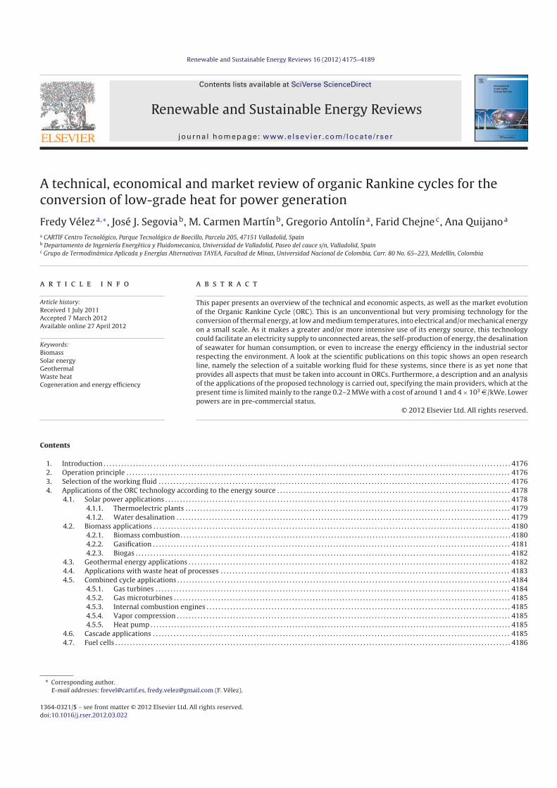
Fig. 8. Cogeneration with ORC technology and biomass combustion.
problems by not using water, easy startingup, reliability and high
efficiency even at partial load [2]. All this puts the relatively low
electrical efficiency of these systems on a secondary level.
The selection of the working fluid in ORC technology systems
with biomass combustion has the peculiarity of working with rel
atively high temperature levels. The temperature of the condenser
can be between 60 and 120 ◦C [18] to satisfy the needs of heat
users. This means that many fluids cannot be used because their
vapor pressure is quite high, even at condensation temperature.
The turbine inlet temperature could be close to flame temperature,
but organic fluids would become chemically unstable. Therefore,
the maximum process temperature is limited to about 330 ◦C [7].
Normally, the heat of the gases from the combustion of biomass is
transferred to the working fluid through a secondary fluid (as in
Fig. 8), a thermal oil that prevents overheating and allows the heat
exchange of exhaust gas at atmospheric pressure, thus achieving
greater process control.
The cost for a commercial ORC module of 1 MWe used for
biomass applications is currently about 1600 D /kWe [22], while
[37] shows how the ORC cogeneration units are viable for typi
cal conditions in the European Union; in which case, the value of
electricity required must be around 10 cD /kWh for power plants
larger than 1.5 MWe, while for 1 MWe plants, the value of electric
ity must be at least 14 cD /kWh. On an industrial scale, in [38], heat
pellet production plants are compared with the CHP solution based
on a biomass combustion system, an ORC unit and a belt dryer fed
by hot water coming from the ORC condenser. That work shows
how CHP plants for productive purposes can be economically com
petitive with a value of electricity over 16 cD /kWh for plants with
a pellet production capacity of 4 t/h, while above 8 t/h, the value of
electricity must be between 10 and 12 cD /kWh.
Regarding microscale CHP facilities, which would be particu
larly useful in the residential sector, in [39], a small scale biomass
powered ORC of 10 kWe was designed, built and tested to pro
duce heat and power and to demonstrate its full operability and/or
technical feasibility. However, it can be said that they are not yet
economically viable, due to the initial investment cost and a long
payback period. In spite of this, even when it is evident that the
savings that this type of technology supposes for primary energy
consumption and the reduction of CO2 emissions; further research
is needed in the development of lowcost microscale CHP systems
with innovative technologies [40].
4.2.2. Gasification
When comparing ORC and gasification technologies for biomass
CHP plants in economic and technical terms, as presented in [41],
it is shown that gasification gives a higher yield, but the initial
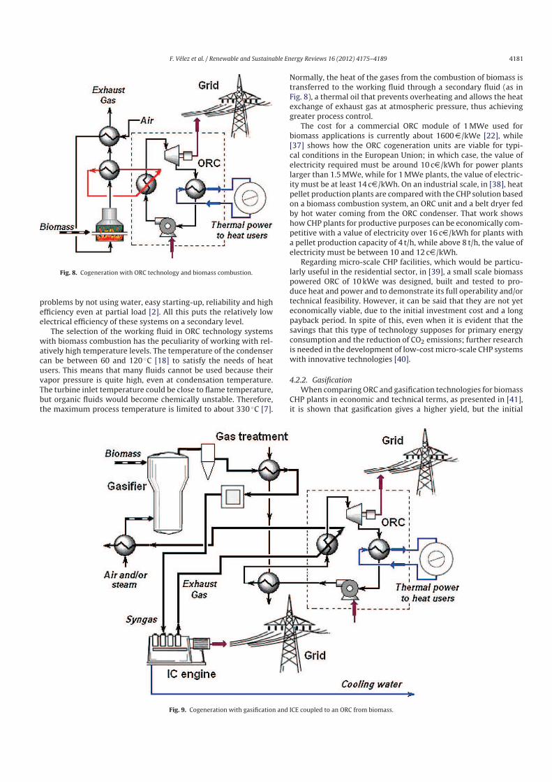
Fig. 9. Cogeneration with gasification and ICE coupled to an ORC from biomass.

4182 F. Vélez et al. / Renewable and Sustainable Energy Reviews 16 (2012) 4175– 4189
Fig. 10. Cogeneration with biogas and ICE coupled to an ORC from biomass.
investment costs and operation and maintenance are a major 75%
and 200% respectively. In addition, there are other parameters in
these plants that are difficult to quantify, such as the state of the
technology (commercial, pilot or demonstration plants), installa
tion time and cost, the risk associated with performance, reliability,
etc. It is worth noting that the ORC has the upper hand in all them.
However, even when it is thought that both technologies are com
petitors as CHP plants, they could also be combined, as shown
schematically in Fig. 9, to increase the kWe produced per kilogram
of fuel used. This is because, in gasification, the heat to be extracted
from the gas cleaning system, as well as the exhausted combustion
gas and the cooling water from the Internal Combustion Engine
(ICE), could be exploited by its incorporation in an ORC, i.e., a com
bination of cycles. This system will be dealt with in detail in Section
4.5.3, given that other potential uses of the gas produced by gasi
fying biomass is combusted in a microturbine or a gas turbine, the
exhaust gases could be used to drive an ORC and thus increase the
kWe produced as described in Section 4.5.3.
Obviously, with this proposed configuration, the fact of being
able to give a use to the residual heat of the ORC condenser (cogen
erate) will depend on the flows and temperature ranges achieved in
the treatment of the syngas and on the ICE, apart from the thermal
needs of the users of that heat.
4.2.3. Biogas
Anaerobic digestion of biomass produces a fuel gas, “biogas”,
which is introduced to an ICE to produce work. Exhausted combus
tion gases emerging from this process are used, in part, to maintain
a condition of optimum temperature in the digester and the sub
strate. However, there is a tremendous amount of waste heat that
cannot be used sometimes, due to its characteristics and the loca
tion of these plants, making this technology currently viable only
with subsidies. Therefore, coupling an ORC to produce more electric
power by using the waste/rejected heat (as presented schemat
ically in Fig. 10), theoretically reaches a cost of 5.65 cD /kWh, as
compared to 13.16 cD /kWh without the ORC [10]. Germany is cur
rently the world leader in the deployment of biogas technology.
Its plants produced, in 2008, about 10 TWh electricity per annum,
which accounts for about 1.6% of the total demand [42]. Moreover,
if we add the fact that in 2007 “alone” a total of 29 TWh of electricity
was produced from biogas in the countries belonging to the Organi
zation for Economic Cooperation and Development (OECD) [43]; it
can be deduced that the potential of the coupling of both technolo
gies is huge, especially when the trend for biogas is towards more
decentralized electricity production in locations with CHP plants
[43].
It should be noted that, depending on the temperature levels of
the processes, the digester can be heated with the cooling water
of the engine, while the ORC is driven by heat from the exhausted
gases. However, according to the explanation in [44], the coupling
of ORC is currently recommended only for biogas plants with output
exceeding 300 kWth and where there is no demand for heat. Similar
results were published by [45], where, due to the marginal gain in
primary energy input to output ratio, the implementation of an
ORC was only recommended for systems that do not include heat
applications in the vicinity of a biogas plant. Moreover, as happens
when the gasification is connected to an ORC (Section 4.2.2), the
fact of giving a use to the waste heat from the condenser (of the
latter) depends on the flows and temperature levels reached in the
exhaust gases of the ICE, as well as on the thermal needs of the
users of that heat.
4.3. Geothermal energy applications
There is an enormous amount of heat available in the world and
which represents one of the most important sources of renewable
energy. However, the possibility of extracting this energy is subject
to a few limited places due to technological and economic reasons
[46,47]. For geothermal energy sources with temperatures above
200 ◦C and producing dry steam or a mixture of steam/brine, the
F. Vélez et al. / Renewable and Sustainable Energy Reviews 16 (2012) 4175– 4189 4183
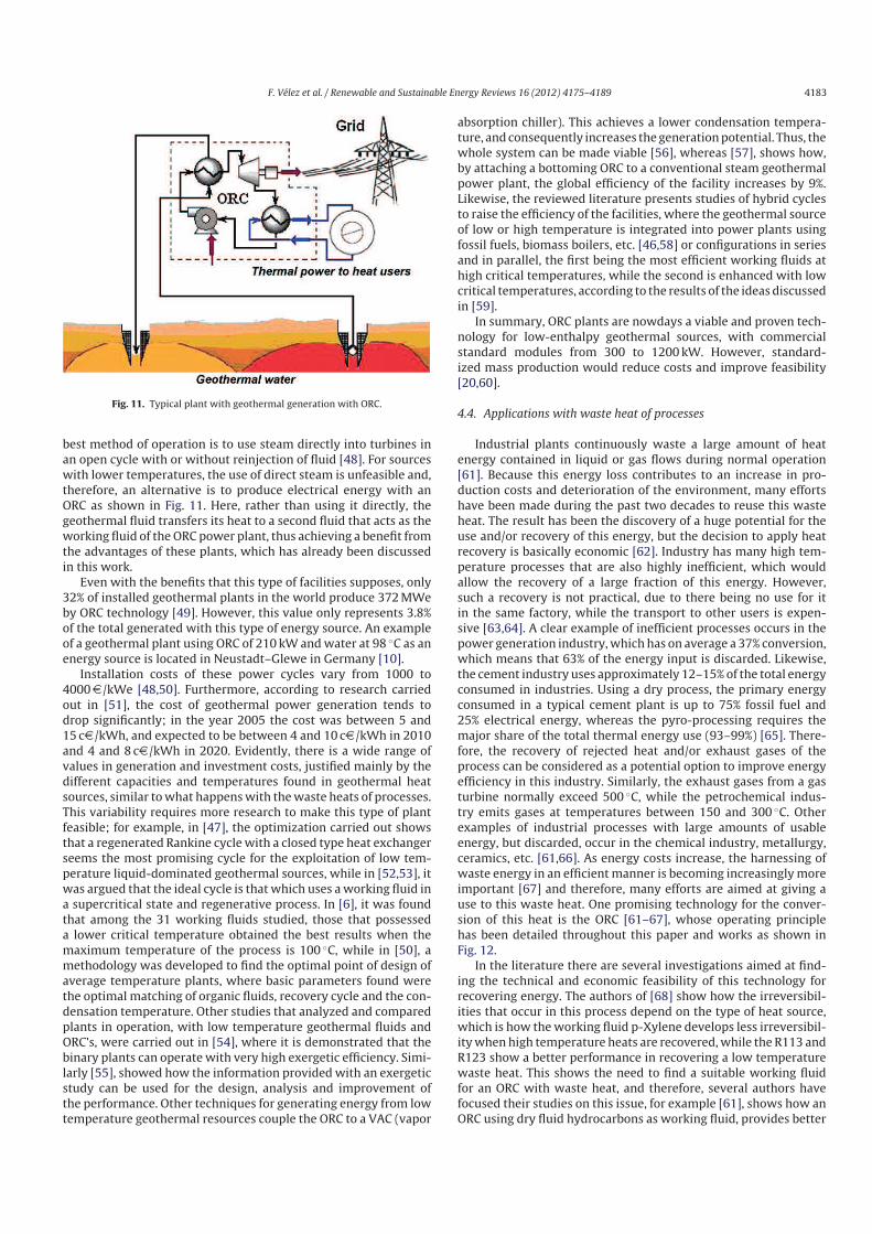
Fig. 11. Typical plant with geothermal generation with ORC.
best method of operation is to use steam directly into turbines in
an open cycle with or without reinjection of fluid [48]. For sources
with lower temperatures, the use of direct steam is unfeasible and,
therefore, an alternative is to produce electrical energy with an
ORC as shown in Fig. 11. Here, rather than using it directly, the
geothermal fluid transfers its heat to a second fluid that acts as the
working fluid of the ORC power plant, thus achieving a benefit from
the advantages of these plants, which has already been discussed
in this work.
Even with the benefits that this type of facilities supposes, only
32% of installed geothermal plants in the world produce 372 MWe
by ORC technology [49]. However, this value only represents 3.8%
of the total generated with this type of energy source. An example
of a geothermal plant using ORC of 210 kW and water at 98 ◦C as an
energy source is located in Neustadt–Glewe in Germany [10].
Installation costs of these power cycles vary from 1000 to
4000 D /kWe [48,50]. Furthermore, according to research carried
out in [51], the cost of geothermal power generation tends to
drop significantly; in the year 2005 the cost was between 5 and
15 cD /kWh, and expected to be between 4 and 10 cD /kWh in 2010
and 4 and 8 cD /kWh in 2020. Evidently, there is a wide range of
values in generation and investment costs, justified mainly by the
different capacities and temperatures found in geothermal heat
sources, similar to what happens with the waste heats of processes.
This variability requires more research to make this type of plant
feasible; for example, in [47], the optimization carried out shows
that a regenerated Rankine cycle with a closed type heat exchanger
seems the most promising cycle for the exploitation of low tem
perature liquiddominated geothermal sources, while in [52,53], it
was argued that the ideal cycle is that which uses a working fluid in
a supercritical state and regenerative process. In [6], it was found
that among the 31 working fluids studied, those that possessed
a lower critical temperature obtained the best results when the
maximum temperature of the process is 100 ◦C, while in [50], a
methodology was developed to find the optimal point of design of
average temperature plants, where basic parameters found were
the optimal matching of organic fluids, recovery cycle and the con
densation temperature. Other studies that analyzed and compared
plants in operation, with low temperature geothermal fluids and
ORC’s, were carried out in [54], where it is demonstrated that the
binary plants can operate with very high exergetic efficiency. Simi
larly [55], showed how the information provided with an exergetic
study can be used for the design, analysis and improvement of
the performance. Other techniques for generating energy from low
temperature geothermal resources couple the ORC to a VAC (vapor
absorption chiller). This achieves a lower condensation tempera
ture, and consequently increases the generation potential. Thus, the
whole system can be made viable [56], whereas [57], shows how,
by attaching a bottoming ORC to a conventional steam geothermal
power plant, the global efficiency of the facility increases by 9%.
Likewise, the reviewed literature presents studies of hybrid cycles
to raise the efficiency of the facilities, where the geothermal source
of low or high temperature is integrated into power plants using
fossil fuels, biomass boilers, etc. [46,58] or configurations in series
and in parallel, the first being the most efficient working fluids at
high critical temperatures, while the second is enhanced with low
critical temperatures, according to the results of the ideas discussed
in [59].
In summary, ORC plants are nowdays a viable and proven tech
nology for lowenthalpy geothermal sources, with commercial
standard modules from 300 to 1200 kW. However, standard
ized mass production would reduce costs and improve feasibility
[20,60].
4.4. Applications with waste heat of processes
Industrial plants continuously waste a large amount of heat
energy contained in liquid or gas flows during normal operation
[61]. Because this energy loss contributes to an increase in pro
duction costs and deterioration of the environment, many efforts
have been made during the past two decades to reuse this waste
heat. The result has been the discovery of a huge potential for the
use and/or recovery of this energy, but the decision to apply heat
recovery is basically economic [62]. Industry has many high tem
perature processes that are also highly inefficient, which would
allow the recovery of a large fraction of this energy. However,
such a recovery is not practical, due to there being no use for it
in the same factory, while the transport to other users is expen
sive [63,64]. A clear example of inefficient processes occurs in the
power generation industry, which has on average a 37% conversion,
which means that 63% of the energy input is discarded. Likewise,
the cement industry uses approximately 12–15% of the total energy
consumed in industries. Using a dry process, the primary energy
consumed in a typical cement plant is up to 75% fossil fuel and
25% electrical energy, whereas the pyroprocessing requires the
major share of the total thermal energy use (93–99%) [65]. There
fore, the recovery of rejected heat and/or exhaust gases of the
process can be considered as a potential option to improve energy
efficiency in this industry. Similarly, the exhaust gases from a gas
turbine normally exceed 500 ◦C, while the petrochemical indus
try emits gases at temperatures between 150 and 300 ◦C. Other
examples of industrial processes with large amounts of usable
energy, but discarded, occur in the chemical industry, metallurgy,
ceramics, etc. [61,66]. As energy costs increase, the harnessing of
waste energy in an efficient manner is becoming increasingly more
important [67] and therefore, many efforts are aimed at giving a
use to this waste heat. One promising technology for the conver
sion of this heat is the ORC [61–67], whose operating principle
has been detailed throughout this paper and works as shown in
Fig. 12.
In the literature there are several investigations aimed at find
ing the technical and economic feasibility of this technology for
recovering energy. The authors of [68] show how the irreversibil
ities that occur in this process depend on the type of heat source,
which is how the working fluid pXylene develops less irreversibil
ity when high temperature heats are recovered, while the R113 and
R123 show a better performance in recovering a low temperature
waste heat. This shows the need to find a suitable working fluid
for an ORC with waste heat, and therefore, several authors have
focused their studies on this issue, for example [61], shows how an
ORC using dry fluid hydrocarbons as working fluid, provides better

4184 F. Vélez et al. / Renewable and Sustainable Energy Reviews 16 (2012) 4175– 4189
Fig. 12. Typical generation plant using waste heat of the processes with ORC.
benefits in terms of power and efficiency; while [69] found the R123
and R124 to be the most appropriate fluids based on a performance
model [70] demonstrated how the efficiency increases as the tem
perature of waste heat used increases and decreases when using
working fluids with low critical temperatures [71] shows how, for
the working fluids with a nonpositive saturation vapor curve slope,
the cycle has the best performance with saturated vapor at the
turbine inlet; while a dynamic model that can assume the con
trol strategy of a cycle, of variable heat source and suitable for the
simulated operation at partial load or during periods of startup and
shutdown, and which aspects cannot be run with a steady model,
is carried out in [72]. On the other hand [73], proposed a system
that combines lowtemperature waste heat and cold energy from
Liquefied Natural Gas (LNG). As for the economic analysis, there are
several research papers that tackle the issue, for example [74], per
formed a parametric analysis of an ORC using R113 as working fluid
where the high sensitivity of the economic viability of the system to
temperatures of condensation, evaporation and overheating can be
appreciated; as well as the effectiveness of the regenerator, denot
ing an optimal combination of these parameters. In the same paper,
other essential aspects to be considered in a project with this tech
nology are explained, such as annual operating hours, unit cost of
electricity and the cost of manufacturing equipment. Similarly [67],
comments that the ORC may be an efficient and cost effective way
to convert residual energy into power, and thus, some examples
of plants in operation are listed. A unit of 40 kWe ORC, designed
for exhaust gases at temperatures between 200 and 250 ◦C and
using tetrachlorethylene as the working fluid, was reported in [75].
The efficiency achieved with this machine was 11%, the estimated
cost was 350 D /kWe and the return period was of 3 years when it
was used in a tunnel kiln in the ceramics industry. Likewise [36],
reported the maintenance costs of an ORC module installed in a
cement plant in Germany to be 0.0007 D /kWh. A graph compiled
in [67] provides an initial idea of the viability of a project with
this type of technology. It relates the temperature of the sources
(heat and condensation), with their respective heat fluids, which
are presented in Fig. 13.
4.5. Combined cycle applications
Because of the wide range of power of the ORC, it can also recover
the waste heat from other power cycles such as turbines and/or
microturbines of gas (see Fig. 14), internal combustion engines
(Fig. 10), or attached to cooling cycles.
The union of these processes forms combined cycles or “mini
cycles”, where the latter, given their small/medium power, are
not feasible with conventional technologies, and this increases the
interest in the use of ORCs for this type of applications. A review of
the status of these technologies is as follows.
Fig. 13. Economic viability of bottoming type plants.
4.5.1. Gas turbines
Day after day technological advances are obtained, and in this
way, for example, the construction of high efficiency gas turbines
has been achieved, one of their characteristics is the relatively low
temperature of the exhaust gases. Thus, a rigorous analysis has
been carried out by [76], where a combined cycle high efficiency
gas turbine with conventional Rankine cycle is compared to a new
combined cycle high efficiency gas turbine with ORC. The over
all efficiency of this new combination increases by up to 3% with
respect to the first alternative (depending on the working fluid).
However, another interesting conclusion is that similar efficien
cies are achieved in both cases (≈60%), but with the difference
of requiring lower inlet temperatures to the gas turbine for the
second option, also obtaining a reduction of NOx and construction
and maintenance costs. Also [76], shows how these new combined
cycles are economically attractive when the cost of the gas turbine
and the ORC are less than 350 D /kW and 2000 D /kW, respec
tively. A similar comparative study for the use of combustion gases
from gas turbines, which are currently being used in compressor
Fig. 14. Combined cycle turbine/microturbine of gas – ORC.

F. Vélez et al. / Renewable and Sustainable Energy Reviews 16 (2012) 4175– 4189 4185
stations for natural gas in Spain, was reported in [77]. The authors
recommended the ORC technology for the production of 5 MWe
as a bottoming cycle, due to its high reliability, low need of per
sonnel, good performance at partial loads that will be submitted
(due to the modulation of compressor stations) and lower invest
ment cost (1500 D /kW for the ORC, compared to 2050 D /kW for the
steam cycle). On the other hand [78], reported the use of cryogenic
energy contained in the LNG. With this aim, these researchers pro
pose a cascading power cycle consisting of a Rankine cycle using
ammonia–water as the working fluid, Brayton power cycle with
combustion gas and an open LNG cycle. Their results show the eco
nomic benefits this process brings, due to the increase of the work
generated by the expansion of the LNG and the reduction of work
consumed by the compressor and pump of the Brayton and Rankine
cycle respectively.
4.5.2. Gas microturbines
A study to analyze the feasibility potential of combining gas
microturbines with microORC was conducted by [79]. These
authors show that, for a 100 kWe microturbine, it is possible to
obtain an additional 45 kW of electricity using residual heat by
means of a microORC and thereby move from an electrical effi
ciency of 30% to 40%. In addition, output gases of the ORC can get
30 kW of low temperature (≈100 ◦C) for cogeneration purposes.
However, these combined minicycles are particularly suitable for
plants where cogeneration (the heat) has little importance as com
pared to the production of electricity. The estimated cost for the
entire system, according to these authors, is about 4000 D /kWe
[79]. The analysis after combining gas microturbines and ORC has
been done by other researchers [80,81], who report periods of
return on investment of less than 3 years for the complete system.
4.5.3. Internal combustion engines
As mentioned at the beginning of this section and as shown in
Fig. 10, the ORC can also recover the waste heat from combustion
gases and/or from cooling systems of the ICE. In this way, it can
form combined cycles, or combined “minicycles”, that obviously
depend on the power of ICE. Several investigations aimed to ana
lyzing the behavior of such processes have been reported in [82,83],
among others. A study that examines the potential for the recovery
of waste heat from a dualfuel, high efficiency, low emissions and
low temperature exhaust gases ICE coupled to the ORC is carried out
in [84]. With this system, an improvement of 7% in the efficiency of
the fuel conversion and a decrease of 18% in specific NOx and CO2
emissions was obtained. This same paper presents a brief summary
of several studies that discuss the issue of heat recovery with ORC,
from the theoretical, simulation, review and experimental points of
view. The authors of [83] analized the recovery of energy contained
in the combustion gases of an ICE under three different configura
tions; a simple cycle using only exhausted gases, a simple cycle
recovering exhausted gases and cooling water of the engine and
finally, a regenerative cycle. This analysis shows an increase of up
to 12% in the overall efficiency with respect to the cycle without any
type of recovery. In addition, they also noted the small amount of
energy that can be recovered from the cooling system of the engine.
The highest values (which are very similar) of efficiency of the com
bined cycle are given for the cases where the ORC is preheated and
regenerative (�cc ≈ 47%).
A thermoeconomic comparison of different configurations and
combined cycles (gas turbine – ORC and gas engine – ORC), involved
in the process of the vaporization of natural gas, has been carried
out by researchers [85]. The results of this research show the great
est efficiency for combined cycles with gas engine, with either one
or two ORCs (51.7% and 54.2%, respectively). However, the spe
cific cost of the plant is higher (1296 and 1475 D /kW) for these
Fig. 15. Rankine cycles in cascade.
configurations, when compared with the proposed combined cycle
with gas turbine – ORC, whose cost is 1028 D /kW.
Investigations carried out to study the feasibility of combined
cycles of ORC coupled to diesel engines have been reported in
works such as [82,86]. The recovery of heat contained in exhaust
gases from two diesel engines, of 8.9 MWe each, has been analyzed
in [82]. The authors compare two technologies for this recovery,
ORC and Kalina cycle and, although the net power obtained after
the recovery is fairly similar (1603 and 1615 kW, respectively), to
obtain a maximum performance, the Kalina cycle requires pres
sures of operation up to 100 bar, while the ORC only requires about
10 bar. Therefore, the adoption of the Kalina cycle is not interesting
for this type of applications, due to its low benefits. Additionally, it
would require a plant resistant to high pressures and with a greater
degree of complexity. A small pilot plant (10–25 kWe) was realized
in [86] to integrate solar energy with a combined cycle of a biodiesel
engine with two ORCs in cascade (see Section 4.6), achieving overall
efficiencies of 41%.
Even when, in the systems discussed below, the waste heat from
one of the cycles is not used by the other, as occurs with the com
bined cycle described before, it is true that there is a coexistence
of two thermodynamic cycles in the same system, since the ORC
is used to recover waste heat from other processes and hence,
the work produced by this directly activates the other cycle. For
example:
4.5.4. Vapor compression
The production of cold by the coupling of a vapor compression
cycle and an ORC was evaluated and its feasibility demonstrated
through a lab scale prototype, which was designed according to the
model developed in the same paper [87]. In the system designed for
5.3 kW, the ORC activates the compressor of the refrigeration cycle
by compression. However, the prototype built showed a slightly
lower cooling capacity, ranging between 3.5 and 4.5 kW.
4.5.5. Heat pump
The coupling of a heat pump with an ORC is another form of
cooling in which, similarly, the ORC acts by contributing to the
mechanical work for the compressor of the heat pump [67].
4.6. Cascade applications
Additionally, and again thanks to its large power ranges and
the diversity of temperatures from the heat source, it is possible to
couple an ORC either to a conventional Rankine cycle or to another
ORC, where the condenser of one acts as an evaporator of the next
and so on, in a cascade, as shown in Fig. 15.

4186 F. Vélez et al. / Renewable and Sustainable Energy Reviews 16 (2012) 4175– 4189
Fig. 16. Evolution (a) and distribution of application (b) of the ORC technology.
An example of these Rankine cycles in cascade is carried out in
[57]. These researchers propose to send a certain amount of steam
from the turbine to a Rankine cycle of conventional steam that oper
ates as a heat source for an ORC. This, in turn, is coupled to another
ORC, in which the first condenser acts as an evaporator for the sec
ond. The results of this study show an increase of 9% in the overall
efficiency of the proposed plant.
On the other hand, a thermodynamic analysis of multiple cycles
of ORCs, with a single working fluid (R113), has been carried out by
[88]. The system produces steam at various pressures and uses 4
evaporators with temperature drops of 120/100, 100/80, 80/60 and
60/40 ◦C, achieving in this way a production of 12.4 kWe, assuming
100 kW of heat recovered from the source of residual heat. Other
works done, in [30,31,89] among others, which take solar radiation
as the energy source, analyze the use of a double cascade ORC for
the production of fresh water through reverse osmosis. In [30] for
example, how the analyzed system can be competitive with con
ventional desalination processes is presented. The main findings,
already illustrated in Section 4.1.2 of this paper, refer to the area of
solar field required per m3 of water, which is much lower than with
traditional solar distillation process. Similarly, reviewing Section
4.1.2 of this paper, the research of [31] was mentioned, which has
a configuration similar to the previous one, but with other work
ing fluids (for lower temperatures). The specific cost of fresh water
was calculated in about 6 D /m3. A cost close to the previous was
found in [89] for the cascade system. This paper presents a rig
orous economic evaluation, in which four processes are analyzed
for producing fresh water by solar radiation and reverse osmosis,
a photovoltaic system (with and without batteries), a low temper
ature ORC and two ORCs coupled in cascade. The latter has a cost
of 6.85 D /m3, significantly similar to those found for systems with
photovoltaic panels, thus becoming a competitive alternative both
economically and technologically.
4.7. Fuel cells
Few studies that examine the results that can be achieved by
coupling the ORC to a fuel cell have been reported. However, the
authors of [90,91] present a theoretical study for trigeneration
plants, where waste heat rejected in a fuel cell SOFT is used to heat
the organic fluid of the ORC. On the other hand, the waste heat of
the ORC is used for heating and/or cooling (the latter through an
absorption chiller of simple effect). The results from these studies
show that the efficiency of the trigeneration plant is 74% (with a
maximum net work produced of 540 kWe), while, if it only had the
plant in cogeneration mode for heating aims, the efficiency would
be 71%, cogeneration with cooling purposes woud be 57% and for
electricity generation by power cycle alone (SOFC and ORC) would
be 46% [90]. Likewise [91], shows how, as the density of the current
of the SOFC increases, the exergetic efficiency for the power cycle
as well as cogeneration for cooling and heating, and even for whole
trigeneration plant, decreases.
5. Manufactures and evolution of the ORC market
As it can be seen from Section 4, the technology associated with
ORC was, until recently, still under investigation. However, demon
stration and commercial plants have recently been developed what
have made that this technology is growing rapidly. Fig. 16a shows
the evolution of the MWe and the number of plants installed up to
2006, according to a study carried out by [92]; while Fig. 16b shows
the distribution by type of application [93]. The market for this tech
nology has experienced such a strong growth in the last 4–5 years
that one single company [18], up to June 2011, had installed almost
the same number of plants as all projects identified in 2006 by [92].
From Fig. 16, we can see that the ORC is a mature technology
for applications with waste heat recovery, biomass and geothermal
sources. However, this is still incipient for applications with a solar
energy source. Furthermore, as shown in Table 1, this technology
is quite well developed for the MW power range, there being very
few ORC plants available in the kW power range, according to the
review of the main manufacturers that produce the ORC technology
worldwide, presented in this same Table 1.
6. Economic analysis
Because of the lack of any real installations to show the cost of
this type of machines, a simple economic analysis has been carried
out to find the maximum investment that a project can assume
when the return on investment is required in a year. The method
ology developed consists of calculating the kWh that 10 kW (for
households) and 100 kW (for the industry) ORC machines can pro
duce, working 8000 h per year and whose fuel cost is none. These
kWh produced mean a maximum saving (in monetary terms) of
not having to buy that amount of energy. However, considering a
10% of fixed operation costs, the maximum reasonable investment

F. Vélez et al. / Renewable and Sustainable Energy Reviews 16 (2012) 4175– 4189 4187
Table 1
Main ORC manufacturers of ORC modules worldwide.
Company/Country Application Range of power (MW) Heat source
temperature (◦C)
Technological aspects Reference
Turboden/Italy 1, 2, 3, 4 0.4–2.2 >250 WF: OMTS, Solkatherm
Efficiency: 17–23%
[18]
Ormat/United States 2, 3, 4 5→ 0.20–22
2 × 10⁻⁴–4 × 10⁻³
150–300 WF: npentane [20]
Pratt & Whitney Power
Systems/United States
1, 2, 3, 4 0.22–0.26 91–149 WF: R245fa [94]
FREEPOWER/England 1, 2, 3, 4 0.12 >110 T: High speed [95]
Infinity Turbine/United States 3, 4 0.01–0.05→
0.25→
<90→
90–120→
WF: R134a
WF: R245fa
[96]
MaxxtecAdoratec/Germany 1, 3, 4 0.3–1.6 >300 WF: OMTS [97]
Barber Nichols/United States 3, 4 0.7, 2.0, 2.7 >115 [98]
GMK/Germany 1, 3, 4 0.5, 2.0 >100 WF: GL160®
WF: WL220®
[99]
LTi REEnergy/Germany 4 0.03 >160 [100]
TRIOGEN/Nederland 4 0.06, 0.16 >350 WF: Toluene
T: Turboexpander
[101]
Eneftech/Switzerland 1, 2, 3, 4 0.005, 0.010→
0.020, 0.030→
>120
<200
T: Scroll [102]
Electratherm/United States 1, 2, 3, 4 0.03–0.05 >88 WF: R245fa
T: Twin Screw Expander
[103]
GE Power & Water/United States 1, 2, 4 0.12 >115
<240
WF: R245fa
T: Single state radial flow
[104]
TransPacific Energy/United States 2, 3, 4 0.10–5.0 >30
<480
WF: TPE® [105]
1, Biomass; 2, solar; 3, geothermal; 4, recovery of heat; 5, remote units. WF, working fluid; T, type of turbine.
Fig. 17. Maximum investment (in the logarithm scale) at industrial and household level for the countries under study.
assumed could be 90% of this saving. Table 2 shows the kWh price
in 2008, for industry as well as for households in various countries
(some EU countries, the USA and Colombia), which is the aim of the
present study.
Fig. 17 presents the results on semilog scale of the previous
economic analysis, which would serve as a first and basic study of a
Table 2
Cost of the kWh in industry and househods in the selected countries.
Country D /kWh Reference
Households Industry
European Union a a [106]
USA 0.0750 0.0455 [107]
Colombia 0.0766 0.0613 [108]
a Variations according to the country as mentioned in [99].
project with ORC technology to be implemented in one of the coun
tries under study. Evidently, where the cost per kWh was higher, a
higher cost of the project can be assumed in both sectors. For exam
ple, for the case of the USA and Colombia, the cost of the project
at residential level is practically equal, whereas for the industrial
sector, a notable difference is detected.
7. Conclusions
Based on the technical review conducted in this work, it can
be stated that the ORC technology, acting as “topping” or “bot
toming” cycle, has an enormous potential, from the technical and
economical point of view, for the production of heat (for heat
ing, domestic hot water, drying processes in industry, absorption
cooling, etc.) and/or for mechanical and electrical energy (from
a few kWe to some MWe) from renewable energy sources such

4188 F. Vélez et al. / Renewable and Sustainable Energy Reviews 16 (2012) 4175– 4189
as biomass, solar and geothermal and waste heat from industrial
processes or other technologies, making them ideal for the energy
selfsufficiency of small populations and industries. This will result
in a continuous increase in the number of companies devoted to
this emerging subject (for implementation, as well as for manufac
turing and distribution), since the lack of low values in fuel costs,
in a certain sense, corrects the relatively low electrical efficiency of
these devices. In addition, it is worth emphasizing the fact that, up
to now, there has been no single fluid that satisfies all aspects that
have to be considered in a real ORC cycle; whereas plants of only a
few kWe are subject to the inclusion of the appropriate equipment
for a strong startup of a business.
Acknowledgments
Support for this work came from the Spanish Ministry of Educa
tion project ENE200914644C0201. The authors acknowledge all
the invaluable comments by Eng. Cecilia Sanz from CARTIF. Fredy
Vélez thanks the scholarship awarded by the “Programa Iberoamer
icano de Ciencia y Tecnología para el Desarrollo”, CYTED, CARTIF
Technological Center and University of Valladolid in order to the
realization of his doctoral thesis, in which this paper is based.
References
[1] Yamamoto T, Furuhata T, Arai N, Mori K. Design and testing of the organicRankine cycle. Energy 2001;26:239–51.
[2] Vélez F, Antolín G. Sistemas de cogeneración mediante ORC. Bioenergy International 2008;1:8–9.
[3] Vélez F, Antolín G, Segovia J, Chejne F. Tecnología ORC como potenciador delas energías no convencionales en zonas no interconectadas y aumento de laeficiencia energética en la industria. In: Proceedings of the 1st world congress& exhibition engineering. 2010.
[4] Hung TC, Shai TY, Wang SK. A review of organic Rankine cycles (ORC‘s) for therecovery of lowgrade waste heat. Energy 1997;22(7):661–7.
[5] Badr O, Probert SD, O’Callaghan PW. Selecting a working fluid for a Rankinecycle engine. Applied Energy 1985;21:1–42.
[6] Saleh B, Koglbauer G, Wendland M, Fischer J. Working fluids for low temperature organic Rankine cycles. Energy 2007;32:1210–21.
[7] Drescher U, Brüggemann D. Fluid selection for the organic Rankine cycle(ORC) in biomass power and heat plants. Applied Thermal Engineering2007;27:223–8.
[8] Tchanche BF, Papadakis G, Lambrinos G, Frangoudakis A. Fluid selection for alowtemperature solar organic Rankine cycle. Applied Thermal Engineering2009;29:2468–76.
[9] Mago PJ, Chamra LM, Srinivasan K, Somayaji C. An examination of regenerative organic Rankine cycles using dry fluids. Applied Thermal Engineering2008;28:998–1007.
[10] Schuster A, Karellas S, Kakaras E, Spliethoff H. Energetic and economic investigation of organic Rankine cycle applications. Applied Thermal Engineering2009;29:1809–17.
[11] Vélez F, Segovia J, Martín MC, Antolín G, Chejne F. Theoretical analysis of atranscritical power cycle for power generation from low temperature heatsource. In: Proceedings of the 24th international conference on efficiency,cost, optimization, simulation and environmental impact of energy systems.2011.
[12] Lemmon EW, Huber ML, Mclinden MO. Reference fluid thermodynamic andtransport properties (REFPROP). NIST Standard Reference Database 23, Version 8.0; 2007.
[13] U.S. Environmental Protection Agency Class I OzoneDepleting Substances. Washington, DC. Available from:<www.epa.gov/ozone/science/ods/classone.html> [accessed 11.03.11].
[14] Chen H, Goswami DY, Stefanakos EK. A review of thermodynamic cycles andworking fluids for the conversion of lowgrade heat. Renewable and Sustainable Energy Reviews 2010;14:3059–67.
[15] Vélez F, Segovia J, Martín MC, Antolín G, Chejne F, Quijano A. Comparativestudy of working fluids for a Rankine cycle operating at low temperature. In:Proceedings of the 4th international congress on energy and environmentengineering and management. 2011.
[16] Vélez F, Antolín G, Chejne F, Valdes C. Selección del fluido de trabajo en lossistemas de cogeneración ORC. In: VI Conferencia Internacional de EnergíaRenovable, Ahorro de Energía y Educación Energética. 2009.
[17] FernándezGarcía A, Zarza E, Valenzuela L, Pérez M. Parabolictrough solarcollectors and their applications. Renewable and Sustainable Energy Reviews2010;14:1695–721.
[18] Clean energy ahead Turboden A Pratt & Whitney Power Systems. Brescia, Italy.Available from: <www.turboden.com> [accessed 11.03.11].
[19] Canada S, Cohen G, Cable R, Brosseau D, Price H. Parabolic trough organicRankine cycle solar power plant. In: Solar energy technologies programreview meeting. 2004.
[20] Ormat Technologies, Inc. Reno, United States. Available from:<www.ormat.com> [accessed 11.03.11].
[21] Agustín D, Lourdes G. Comparison of solar technologies for driving adesalination system by means of an organic Rankine cycle. Desalination2007;216:276–91.
[22] Joan B, Jesús L, Eduardo L, Silvia R, Alberto C. Modelling and optimisation ofsolar organic Rankine cycle engines for reverse osmosis desalination. AppliedThermal Engineering 2008;28:2212–26.
[23] Rayegan R, Tao YX. A procedure to select working fluids for Solar OrganicRankine Cycles (ORCs). Renewable Energy 2011;36:659–70.
[24] Robert B. Current costs of solar powered organic Rankine cycle engines. SolarEnergy 1977;20:1–6.
[25] Wang JL, Zhao L, Wang XD. A comparative study of pure and zeotropicmixtures in lowtemperature solar Rankine cycle. Applied Energy2010;87:3366–73.
[26] Gang P, Jing L, Jie J. Analysis of low temperature solar thermal electric generation using regenerative organic Rankine cycle. Applied Thermal Engineering2010;30:998–1004.
[27] Hung T, Wang S, Kuo C, Pei B, Tsai K. A study of organic working fluidson system efficiency of an ORC using lowgrade energy sources. Energy2010;35:1403–11.
[28] Agustín D, Lourdes G. Preliminary design of seawater and brackishwater reverse osmosis desalination systems driven by lowtemperaturesolar organic Rankine cycle (ORC). Energy Conversion and Management2010;51:2913–20.
[29] Lourdes G, Agustín D. Solarpowered Rankine cycles for fresh water production. Desalination 2007;212:319–27.
[30] Agustín D, Lourdes G. Double cascade organic Rankine cycle for solardrivenreverse osmosis desalination. Desalination 2007;216:306–13.
[31] Kosmadakis G, Manolakos D, Papadakis G. Parametric theoretical study of atwostage solar organic Rankine cycle for RO desalination. Renewable Energy2010;35:989–96.
[32] Lourdes G, Julián B. Solarheated Rankine cycles for water and electricityproduction: POWERSOL project. Desalination 2007;212:311–8.
[33] Manolakos D, Mohameda E, Karagiannis I, Papadakisa G. Technical and economic comparison between PVRO system and ROsolar Rankine system. Casestudy: Thirasia island. Desalination 2008;221:37–46.
[34] Manolakos D, Papadakisa G, Kyritsisa S, Bouzianasb K. Experimental evaluation of an autonomous lowtemperature solar Rankine cycle system forreverse osmosis desalination. Desalination 2007;203:366–74.
[35] Ruyck J, Delattin F, Bram F. Coutilization of biomass and natural gas in combined cycles through primary steam reforming of the natural gas. Energy2007;32:371–7.
[36] David G, Michel F. Small scale biomass power plant using organic Rankinecycle technology. SAS Enertime; 2008.
[37] Duvia A, Guercio A. Technical and economics aspects of biomass fuelled CHPplants based on ORC turbogenerator feeding existing district heating networks. In: Proceedings of the 17th biomass conference and exhibition. 2009.
[38] Duvia A, Tavolo S. Application of ORC units in the pellet production field:technical–economic considerations and overview of the operational resultsof an ORC plant in the industry installed in Mudau (Germany). In: Proceedingsof the 16th Biomass conference and exhibition. 2008.
[39] Brignoli V, Malidin A, Colombo D. Small scale biomass powered organic Rankine cycle turbo generator. In: Proceedings of the 16th biomass conference andexhibition. 2008.
[40] Dong L, Liu H, Riffat S. Development of smallscale and microscale biomassfuelled CHP systems A literature review. Applied Thermal Engineering2009;29:2119–26.
[41] Rentizelas A, Karellas S, Kakaras E, Tatsiopoulos I. Comparative technoeconomic analysis of ORC and gasification for bioenergy applications. EnergyConversion and Management 2009;50:674–81.
[42] Poeschl M, Ward S, Owende P. Prospects for expanded utilization of biogas inGermany. Renewable and Sustainable Energy Reviews 2010;14:1782–97.
[43] Andreas W, Martin K, Woo Y. Renewable power generation—a status report.Renewable Energy Focus 2009:68.
[44] Schulz W, Heitmann S, Hartmann D, Manske S, Peters ES, Risse S. Utilization of heat excess from agricultural biogas plants. Bremen Germany: BremerEnergie Institut, Universität Bremen, Institut für Umweltverfahrenstechnik;2007.
[45] Martina P, Shane W, Philip O. Evaluation of energy efficiency of various biogasproduction and utilization pathways. Applied Energy 2010;87:3305–21.
[46] Gianni B, Umberto D, Francesco DM. A single flash integrated gas turbinegeothermal power plant with non condensable gas combustion. Geothermics1999;28:131–50.
[47] Desideri U, Bidini G. Study of possible optimisation criteria forgeothermal power plants. Energy Conversion and Management1997;38(15–17):1681–91.
[48] Heard C, Fernandez H, Holland F. Development in geothermal energyin Mexicopart twenty seven: the potential for geothermal organicRankine cycle power plants in Mexico. Heat Recovery Systems & CHP1990;10(2):79–86.
[49] Dipippo R. Geothermal power plants: principles, applicants, case studies andenvironmental impact. 2nd ed. Elsevier; 2008.

F. Vélez et al. / Renewable and Sustainable Energy Reviews 16 (2012) 4175– 4189 4189
[50] Franco A, Villani M. Optimal design of binary cycle power plants forwaterdominated, mediumtemperature geothermal fields. Geothermics2009;38:379–91.
[51] Lukawski M. Design and optimization of standardized organic Rankine cyclepower plant for European conditions. Master’s thesis. University of Iceland &the University of Akureyri, Akureyri, Iceland; February 2009.
[52] Gu Z, Sato H. Optimization of cyclic parametres of a supercritical cyclefor geothermal power generation. Energy Conversion and Management2001;42:1409–16.
[53] Gu Z, Sato H. Performance of supercritical cycles for geothermal binary design.Energy Conversion and Management 2002;43:961–71.
[54] DiPippo. R. Second Law assessment of binary plants generating power fromlowtemperature geothermal fluids. Geothermics 2004;33:565–86.
[55] Kanoglua M, Bolatturk A. Performance and parametric investigationof a binary geothermal power plant by exergy. Renewable Energy2008;33:2366–74.
[56] Mohanty B, Paloso G. Economic power generation from low temperature geothermal resources using organic Rankine cycle combined withvapour absorption chiller. Heat Recovery Systems & CHP 1992;12(2):143–58.
[57] Rosyid H, Koestoer R, Putra N, Nasruddin, Mohamad, Yanuar A. Sensitivityanalysis of steam power plantbinary cycle. Energy 2010;35:3578–86.
[58] Borsukiewicz GA. Dualfluidhybrid power plant copowered by lowtemperature geothermal water. Geothermics 2010;39:170–6.
[59] Heberle F, Brüggemann D. Exergy based fluid selection for a geothermalorganic Rankine cycle for combined heat and power generation. Applied Thermal Engineering 2010;30:1326–32.
[60] Bronicki L. Electrical power from moderated temperature geothermal sourceswith modular minipower plants. Geothermics 1988;17(1):83–92.
[61] Nguyen T, Slawnwhite J, Goni K. Power generation from residual industrialheat. Energy Conversion and Management 2010;51:2220–9.
[62] AlRabghi O, Beirutty M, Akyurt M, Najjar Y, Alp T. Recovery and utilizationof waste heat. Heat Recovery Systems & CHP 1993;13(5):463–70.
[63] Casci C, Angelino G, Ferrari P, Gaia M, Giglioli G, Macchi E. Heat recovery ina ceramic kiln with an organic Rankine cycle engine. Heat Recovery Systems1981;1:125–31.
[64] Wei D, Lu X, Lu Z, Gu J. Performance analysis and optimization of organic Rankine cycle (ORC) for waste heat recovery. Energy Conversion and Management2007;48:1113–9.
[65] Madlool NA, Saidur R, Hossain MS, Rahimb NA. A critical review on energyuse and savings in the cement industries. Renewable and Sustainable EnergyReviews 2011;15:2042–60.
[66] Larjola J. Electricity from industrial waste heat using highspeed organicRankine cycle (ORC). International Journal of Production Economics1995;41:227–35.
[67] Sternlicht B. Waste energy recovery: an excellent investment opportunity.Energy Conversion and Management 1982;22:361–73.
[68] Hung TC. Waste heat recovery of organic Rankine cycle using dry fluids.Energy Conversion and Management 2001;42:539–53.
[69] Maizza V, Maizza A. Unconventional working fluids in organic Rankinecycles for waste energy recovery systems. Applied Thermal Engineering2001;21:381–90.
[70] Liu BT, Chien KH, Wang CC. Effect of working fluids on organic Rankine cyclefor waste heat recovery. Energy 2004;29:1207–17.
[71] Dai Y, Wang J, Gao L. Parametric optimization and comparative study oforganic Rankine cycle (ORC) for low grade waste heat recovery. Energy Conversion and Management 2009;50:576–82.
[72] Quoilin S, Aumann R, Grill A, Schuster A, Lemort V, Spliethoff H. Dynamic modeling and optimal control strategy of waste heat recovery organic Rankinecycles. Applied Energy 2011;88:2183–90.
[73] Shi X, Che D. A combined power cycle utilizing lowtemperature wasteheat and LNG cold energy. Energy Conversion and Management 2009;50:567–75.
[74] Lee K, Kuo S, Chien M, Shih Y. Parameters analysis on organic Rankine cycle energy recovery system. Energy Conversion and Management1988;28(2):129–36.
[75] Reay D. Heat recoveryresearch and development within the European Community. Heat Recovery Systems 1982;2(56):419–36.
[76] Chacartegui R, Sánchez D, Munoz JM, Sánchez T. Alternative ORC bottoming cycles for combined cycle power plants. Applied Energy 2009;86:2162–70.
[77] Gutiérrez L, López J. Residual heat to power generation in a compression station of Enagas (Spain). In: Proceedings of the 24th World Gas Conference.2009.
[78] Lu T, Wang KS. Analysis and optimization of a cascading power cycle with liquefied natural gas (LNG) cold energy recovery. Applied Thermal Engineering2009;29:1478–84.
[79] Invernizzi C, Iora P, Silva P. Bottoming microRankine cycles for microgasturbines. Applied Thermal Engineering 2007;27:100–10.
[80] Najjar Y, Radhwan A. Cogeneration by combining gas turbine enginewith organic Rankine cycle. Heat Recovery Systems & CHP 1988;8(3):211–9.
[81] Najjar Y. Efficient use of energy by utilizing gas turbine combined systems.Applied Thermal Engineering 2001;21:407–38.
[82] Bombarda P, Invernizzi C, Pietra C. Heat recovery from Diesel engines: a thermodynamic comparison between Kalina and ORC cycles. Applied ThermalEngineering 2010;30:212–9.
[83] Vaja I, Gambarotta A. Internal combustion engine (ICE) bottoming withorganic Rankine cycles (ORCs). Energy 2010;35:1084–93.
[84] Srinivasan K, Mago P, Krishnan S. Analysis of exhaust waste heat recoveryfrom a dual fuel low temperature combustion engine using an organic Rankine cycle. Energy 2010;35:2387–99.
[85] Querol E, Gonzalez RB, García TJ, Ramos A. Available power generation cyclesto be coupled with the liquid natural gas (LNG) vaporization process in a Spanish LNG terminal. Applied Energy 2011, doi:10.1016/j.apenergy.2011.01.023.
[86] Kane M, Larrain D, Favrat D, Allani Y. Small hybrid solar power system. Energy2003;28:1427–43.
[87] Wang H, Peterson R, Harada K, Miller E, Ingram GR, Fisher L, et al. Performanceof a combined organic Rankine cycle and vapor compression cycle for heatactivated cooling. Energy 2011;36:447–58.
[88] Gnutek Z, Bryszewska MA. The thermodynamic analysis of multicycle ORCengine. Energy 2001;26:1075–82.
[89] Kosmadakis G, Manolakos D, Kyritsis S, Papadakis G. Economic assessmentof a twostage solar organic Rankine cycle for reverse osmosis desalination.Renewable Energy 2009;34:1579–86.
[90] AlSulaiman F, Dincer I, Hamdullahpur F. Energy analysis of a trigenerationplant based on solid oxide fuel cell and organic Rankine cycle. InternationalJournal of Hydrogen Energy 2010;35:5104–13.
[91] AlSulaiman F, Dincer I, Hamdullahpur F. Exergy analysis of an integratedsolid oxide fuel cell and organic Rankine cycle for cooling, heating and powerproduction. Journal of Power Sources 2010;195:2346–54.
[92] Enertime. Paris, France. Available from: <www.enertime.com> [accessed11.03.11].
[93] Sylvain Q, Vincent L. Technological and economical survey of organic Rankinecycle systems. In: Proceedings of the 5th European conference economics andmanagement of energy in industry. 2009.
[94] Pratt & Whitney Power Systems. A United Technologies Company. East Hartford, United States. Available from: <www.pw.utc.com> [accessed 11.03.11].
[95] Freepower Company. Wiltshire, England. Available from:<www.freepower.co.uk> [accessed 11.03.11].
[96] Global Energy and Infinity Turbine LLC. Madison, United States. Availablefrom: <www.infinityturbine.com> [accessed 11.03.11].
[97] Maxxtec AG. Sinsheim, Germany. Available from: <www.maxxtec.com>[accessed 11.03.11].
[98] BarberNichols Inc. Arvada, United States. Available from: <www.barbernichols.com> [accessed 11.03.11].
[99] GMK – Gesellschaft für Motoren und Kraftanlagen mbH. Bargeshagen,Germany. Available from: <www.gmk.info/welcome.23.html> [accessed11.03.11].
[100] LTi REEnergy GmbH. Unna, Germany. Available from: <http://reenergy.lti.com> [accessed 11.03.11].
[101] TriOGen B.V. Goor, Nederland. Available from: <www.triogen.nl> [accessed11.03.11].
[102] Eneftech Innovation SA. Nyon, Switzerland. Available from:<www.eneftech.com> [accessed 11.03.11].
[103] ElectraTherm, Inc. Nevada, United States. Available from:<www.electratherm.com> [accessed 11.03.11].
[104] GE Power & Water Heat Recovery Solutions. Stuart, United States. Availablefrom: <www.geheatrecovery.com> [accessed 11.03.11].
[105] TransPacific Energy, Inc. Carson City, United States. Available from:<www.transpacenergy.com> [accessed 11.03.11].
[106] EUROPA – the official web site of the European Union. Brussels,Belgium: Statistical Office of the European Communities. Available from:<www.epp.eurostat.ec.europa.eu> [accessed 17.11.10].
[107] U.S. Energy Information Administration (EIA). Washington, DC. Availablefrom: <www.eia.doe.gov> [accessed 15.08.10].
[108] Unidad de Planeación Minero Energética. Bogotá, Colombia. Available from:<www.upme.gov.co> [accessed 15.08.10].