Embed Size (px)
Citation preview
T
BD
a
ARAA
KTHCN
C
1d
Renewable and Sustainable Energy Reviews 15 (2011) 4013–4029
Contents lists available at ScienceDirect
Renewable and Sustainable Energy Reviews
journa l homepage: www.e lsev ier .com/ locate / rser
ranscritical carbon dioxide heat pump systems: A review
rian T. Austin, K. Sumathy ∗
epartment of Mechanical Engineering, North Dakota State University, Fargo, ND 58103, USA
r t i c l e i n f o
rticle history:eceived 28 December 2010ccepted 5 July 2011vailable online 21 August 2011
a b s t r a c t
Carbon dioxide is a safe, economic and environmentally sustainable refrigerant which can be used in heatpump and refrigeration systems. Research into the performance and benefits of a transcritical heat pumpcycle using carbon dioxide began in the early 1990s. Theoretical and experimental research, as well ascommercial system development, has improved transcritical system performance to a level similar to
eywords:ranscritical cycleeat pumpO2
atural refrigerant
that of conventional heat pump systems. This paper presents an overview of transcritical carbon dioxideheat pump systems. The paper begins with a summary of carbon dioxide’s use as a refrigerant and thedistinctions of the transcritical cycle, followed by a numerical analysis of transcritical cycle performance.The study will then present a review of research on transcritical carbon dioxide heat pump systems,which covers system components, configurations and modifications and how these factors affect overallsystem performance.
Published by Elsevier Ltd.
ontents
1. Introduction . . . . . . . . . . . . . . . . . . . . . . . . . . . . . . . . . . . . . . . . . . . . . . . . . . . . . . . . . . . . . . . . . . . . . . . . . . . . . . . . . . . . . . . . . . . . . . . . . . . . . . . . . . . . . . . . . . . . . . . . . . . . . . . . . . . . . . . . 40142. Unique properties of carbon dioxide . . . . . . . . . . . . . . . . . . . . . . . . . . . . . . . . . . . . . . . . . . . . . . . . . . . . . . . . . . . . . . . . . . . . . . . . . . . . . . . . . . . . . . . . . . . . . . . . . . . . . . . . . . . . . . 40143. A brief history of CO2’s use as a refrigerant . . . . . . . . . . . . . . . . . . . . . . . . . . . . . . . . . . . . . . . . . . . . . . . . . . . . . . . . . . . . . . . . . . . . . . . . . . . . . . . . . . . . . . . . . . . . . . . . . . . . . . . 40144. Comparison of conventional and transcritical heat pump systems . . . . . . . . . . . . . . . . . . . . . . . . . . . . . . . . . . . . . . . . . . . . . . . . . . . . . . . . . . . . . . . . . . . . . . . . . . . . . . . 40155. Modeling and analysis . . . . . . . . . . . . . . . . . . . . . . . . . . . . . . . . . . . . . . . . . . . . . . . . . . . . . . . . . . . . . . . . . . . . . . . . . . . . . . . . . . . . . . . . . . . . . . . . . . . . . . . . . . . . . . . . . . . . . . . . . . . . . 4015
5.1. Thermodynamic analysis . . . . . . . . . . . . . . . . . . . . . . . . . . . . . . . . . . . . . . . . . . . . . . . . . . . . . . . . . . . . . . . . . . . . . . . . . . . . . . . . . . . . . . . . . . . . . . . . . . . . . . . . . . . . . . . . . . . 40165.1.1. Gas cooler . . . . . . . . . . . . . . . . . . . . . . . . . . . . . . . . . . . . . . . . . . . . . . . . . . . . . . . . . . . . . . . . . . . . . . . . . . . . . . . . . . . . . . . . . . . . . . . . . . . . . . . . . . . . . . . . . . . . . . . . . 40165.1.2. Evaporator . . . . . . . . . . . . . . . . . . . . . . . . . . . . . . . . . . . . . . . . . . . . . . . . . . . . . . . . . . . . . . . . . . . . . . . . . . . . . . . . . . . . . . . . . . . . . . . . . . . . . . . . . . . . . . . . . . . . . . . . 40165.1.3. Compressor . . . . . . . . . . . . . . . . . . . . . . . . . . . . . . . . . . . . . . . . . . . . . . . . . . . . . . . . . . . . . . . . . . . . . . . . . . . . . . . . . . . . . . . . . . . . . . . . . . . . . . . . . . . . . . . . . . . . . . . 40165.1.4. Expansion device . . . . . . . . . . . . . . . . . . . . . . . . . . . . . . . . . . . . . . . . . . . . . . . . . . . . . . . . . . . . . . . . . . . . . . . . . . . . . . . . . . . . . . . . . . . . . . . . . . . . . . . . . . . . . . . . . 4017
5.2. CO2 transport characteristics . . . . . . . . . . . . . . . . . . . . . . . . . . . . . . . . . . . . . . . . . . . . . . . . . . . . . . . . . . . . . . . . . . . . . . . . . . . . . . . . . . . . . . . . . . . . . . . . . . . . . . . . . . . . . . 40175.2.1. Heat transfer correlations: supercritical cooling. . . . . . . . . . . . . . . . . . . . . . . . . . . . . . . . . . . . . . . . . . . . . . . . . . . . . . . . . . . . . . . . . . . . . . . . . . . . . . . . . 40175.2.2. Pressure drop correlations: supercritical flow . . . . . . . . . . . . . . . . . . . . . . . . . . . . . . . . . . . . . . . . . . . . . . . . . . . . . . . . . . . . . . . . . . . . . . . . . . . . . . . . . . . 40175.2.3. Heat transfer and pressure drop correlations: flow boiling . . . . . . . . . . . . . . . . . . . . . . . . . . . . . . . . . . . . . . . . . . . . . . . . . . . . . . . . . . . . . . . . . . . . . 4017
6. Performance of transcritical CO2 heat pump systems. . . . . . . . . . . . . . . . . . . . . . . . . . . . . . . . . . . . . . . . . . . . . . . . . . . . . . . . . . . . . . . . . . . . . . . . . . . . . . . . . . . . . . . . . . . . . 40186.1. Performance characteristics of basic systems . . . . . . . . . . . . . . . . . . . . . . . . . . . . . . . . . . . . . . . . . . . . . . . . . . . . . . . . . . . . . . . . . . . . . . . . . . . . . . . . . . . . . . . . . . . . . 40186.2. Component and system modifications . . . . . . . . . . . . . . . . . . . . . . . . . . . . . . . . . . . . . . . . . . . . . . . . . . . . . . . . . . . . . . . . . . . . . . . . . . . . . . . . . . . . . . . . . . . . . . . . . . . . . 4020
6.2.1. Heat exchanger modifications . . . . . . . . . . . . . . . . . . . . . . . . . . . . . . . . . . . . . . . . . . . . . . . . . . . . . . . . . . . . . . . . . . . . . . . . . . . . . . . . . . . . . . . . . . . . . . . . . . . 40206.2.2. Compression process modifications . . . . . . . . . . . . . . . . . . . . . . . . . . . . . . . . . . . . . . . . . . . . . . . . . . . . . . . . . . . . . . . . . . . . . . . . . . . . . . . . . . . . . . . . . . . . . 40226.2.3. Expansion process modifications . . . . . . . . . . . . . . . . . . . . . . . . . . . . . . . . . . . . . . . . . . . . . . . . . . . . . . . . . . . . . . . . . . . . . . . . . . . . . . . . . . . . . . . . . . . . . . . . 4023
7. Future potential of transcritical CO2 heat pump systems . . . . . . . . . . . . . . . . .8. Conclusion . . . . . . . . . . . . . . . . . . . . . . . . . . . . . . . . . . . . . . . . . . . . . . . . . . . . . . . . . . . . . . . . . .
References . . . . . . . . . . . . . . . . . . . . . . . . . . . . . . . . . . . . . . . . . . . . . . . . . . . . . . . . . . . . . . . . . .
∗ Corresponding author at: North Dakota State University, Dept 2490, PO Box 6050, FarE-mail address: [email protected] (K. Sumathy).
364-0321/$ – see front matter. Published by Elsevier Ltd.oi:10.1016/j.rser.2011.07.021
. . . . . . . . . . . . . . . . . . . . . . . . . . . . . . . . . . . . . . . . . . . . . . . . . . . . . . . . . . . . . . . . . . . . . . . . 4026. . . . . . . . . . . . . . . . . . . . . . . . . . . . . . . . . . . . . . . . . . . . . . . . . . . . . . . . . . . . . . . . . . . . . . . 4027. . . . . . . . . . . . . . . . . . . . . . . . . . . . . . . . . . . . . . . . . . . . . . . . . . . . . . . . . . . . . . . . . . . . . . . 4027
go, ND 58108, USA. Tel.: +1 701 231 7139; fax: +1 701 231 8913.

4014 B.T. Austin, K. Sumathy / Renewable and Sustaina
Nomenclature
A heat transfer area, m2
COP coefficient of performancecp specific heat, kJ/kg Kd diameterG mass flux, kg/m2
h specific enthalpy, kJ/kgL length, mm mass flow rate, kg/sN compressor speed, HzNu Nusselt numberP pressure, PaPr Prandl numberQ heat transfer rate, Wqw heat flux through the tube wall, W/m2
r compressor pressure ratioRe Reynolds numberT temperature, ◦C�Tap approach temperature difference, ◦CU overall heat transfer coefficient, W/m2 KVs swept volume of compressor, m3
Wcomp compressor work, W
Greek lettersf friction factorfc friction factor at constant thermophysical proper-
ties� efficiency� dynamic viscosity, N/m2 s� minor loss coefficient� density, kg/m3
Subscriptsb bulk temperaturecomp compressorcrit criticalev evaporatorexp expansion devicegc gas cooleri inlet; inneris isentropico outletpc pseudo criticalv volumetric
1
dTogeafweaoa
a
w water; wall temperature
. Introduction
Climate change is a major worldwide concern with potentiallyramatic impacts on developing and industrialized countries alike.he effort to mitigate climate change centers on the reductionf greenhouse gas emissions. Carbon dioxide is the greenhouseas which receives the most attention due to sheer volume ofmissions, much of it from power generation. However, othertmospheric pollutants such as methane and nitrous oxide have aar greater impact on climate change on a per mass basis. The globalarming potential (GWP) is a relative measure of the heat trapping
ffect of a gas in comparison to an equal mass of carbon dioxide overgiven quantity of time in the atmosphere [1]. Methane and nitrous
xide have GWP values of 23 and 296 respectively, both based on100 year time span [2].The goal of reducing greenhouse gas emissions has becomemajor driver of technology. Transportation, energy production,
ble Energy Reviews 15 (2011) 4013–4029
agriculture and manufacturing sectors have all sought technologi-cal changes in order to reduce emissions. The heating, ventilation,air conditioning and refrigeration (HVAC&R) industry is also devel-oping systems with lower impacts on climate change.
Many of the refrigerants used in HVAC&R systems are potentgreenhouse gases. R134a, for instance, has a GWP of 1300 over a 100year time span [2]. When securely contained in a properly operatingsystem refrigerants do not impact climate change; however, systemleaks and improper recovery of refrigerants during repairs or atend of life result in these harmful gases entering the atmosphere.Some climatologists have called for a complete worldwide phase-out of refrigerants with high GWP similar to the phase-out of ozonedepleting substances enacted under the Montreal Protocol in 1987.Already, the European Union has approved the scheduled phase-out of mobile air conditioning systems using refrigerants with GWPgreater than 150. This directive was ratified in 2007 and went intoeffect beginning in 2008 [3,4].
One potential replacement refrigerant is carbon dioxide, a nat-ural refrigerant which has negligible impact on climate change.Carbon dioxide used in HVAC&R systems has a zero net impact onclimate change because it has been recovered from other indus-trial processes [5]. Furthermore, carbon dioxide (CO2) is not toxic,flammable or corrosive, and it has no impact on the ozone layer. Itis inexpensive and readily available. CO2’s performance as a refrig-erant in heat pump systems is also competitive with refrigerantscurrently in use [5–7].
2. Unique properties of carbon dioxide
Two factors require special attention when using CO2 as a refrig-erant for heat pump systems. One is the low critical temperature.The other is the high working pressure required to use CO2 undertypical heat pump conditions.
Carbon dioxide becomes a super critical fluid at 31.1 ◦C at73.7 bar. In a conventional (subcritical) heat pump cycle, low criticaltemperature (Tcrit) is a disadvantage because it limits the operat-ing temperature range; heat cannot be delivered at temperaturesgreater than the critical temperature. Further, at temperatures lessthan but near Tcrit, the enthalpy of vaporization is reduced. Thisleads to a reduction in heating capacity and poor performance ofthe system [6]. Thus a conventional heat pump should avoid oper-ating at a heat rejection temperature near Tcrit. In a transcriticalheat pump, heat rejection pressures are greater than the supercrit-ical pressure and heat delivery temperatures are no longer limitedby Tcrit. CO2’s low critical temperature provides the opportunity tooperate in a transcritical manner.
High working pressure is the other notable distinction of CO2heat pumps. Both subcritical and transcritical heat pump systemsusing CO2 operate at pressures greater than with most other refrig-erants. Subcritical CO2 heat pumps may function at pressures ashigh as 60–70 bar, while transcritical systems may have pressuresfrom 80 to 110 bar or more. For comparison, R134a has a saturationpressure of 13.18 bar at 50 ◦C [8].
High pressure presents design challenges in terms of componentrobustness and compressor capability; however, today’s manufac-turing capabilities allow production of components which can meetthese demands. In addition, high pressure presents some benefits:CO2 has a relatively high vapor density and correspondingly a highvolumetric heating capacity. This allows a smaller volume of CO2to be cycled to achieve the same heating demand which allows forsmaller components and a more compact system [5,6].
3. A brief history of CO2’s use as a refrigerant
Heat pump systems are closely related to refrigeration systems,but vapor compression cycles were developed for refrigeration long

staina
bihP
memtpaAlcbh
Cnsttdrotlga
acarainoc
tsaatLawlaoa[mf
schJhiCtav
B.T. Austin, K. Sumathy / Renewable and Su
efore the concept was applied to heating. Likewise, refrigerant flu-ds were developed for refrigeration rather than heating. A detailedistory of CO2’s role in refrigeration development was given byearson [9].
Carbon dioxide was among the first refrigerants used in com-ercially viable vapor compression refrigeration systems. Other
arly refrigerants included ether, ammonia, sulfur dioxide andethyl chloride. CO2 was first used in a vapor compression sys-
em to produce ice by Thaddeus Lowe in 1866. The high workingressures of CO2 were a hindrance to implementation, allowingmmonia and sulfur dioxide systems to become established first.mmonia systems were generally efficient, but they were quite
arge and ammonia’s toxic nature presented a safety hazard. Inomparison, CO2 required more fuel and more robust components,ut the systems were much smaller and CO2 leaks did not pose aealth risk.
For its improved safety and compactness ships began to useO2 for refrigeration in the 1880s and 90s, while on land ammo-ia was dominant. A further reason for the divergence of land andea systems respectively to ammonia and CO2 was condensingemperature and means of condensing. Due to CO2’s low criticalemperature, significant loss of capacity and efficiency occur as con-enser temperature increases. Ammonia can operate under a widerange of condenser temperatures. Early systems mainly used riverr sea water as the heat sink for condensing. This provided the lowemperatures required for CO2. Later, evaporative coolers were uti-ized when a body of water was unavailable. Evaporative coolersenerally produce higher condensing temperatures which favoredmmonia over CO2.
The land and sea trend continued into the early 1900s whenmmonia’s improved safety record and better manufacturingaused acceptance of ammonia refrigeration on ships. By the 1930smmonia plants were preferred even at sea and the use of CO2 forefrigeration further decreased. The final demise of CO2 in refriger-tion was caused by synthetic refrigerants. R12 and R11 were firstntroduced for commercial use in 1931 and 1932 [10]. They wereon-toxic, non-flammable and operated efficiently over a rangef temperatures. Synthetic refrigerants began to displace CO2 andame to dominate non-industrial systems by the 1950s and 60s.
Interest in CO2 was renewed in the early 1990s in part due tohe phase-out of ozone depleting refrigerants. Norwegian profes-or Gustav Lorentzen has received much of the credit for the newttention given to CO2, however, there were others studying CO2t the same time. Lorentzen published a patent application for arans-critical CO2 automotive air conditioning system in 1990 [11].orentzen’s transcritical cycle eliminates the problem of capacitynd efficiency loss that subcritical systems have when operatingith heat rejection temperatures near the critical point. Techno-
ogical and manufacturing improvements make it possible now tochieve the high pressures required for transcritical operation. Onef the first transcritical CO2 systems was a prototype automotiveir conditioning system built and tested by Lorentzen and Pettersen12]. The system was further reported by Pettersen [13]. Perfor-
ance was similar to that of an R12 system and encouraged theurther development of the transcritical CO2 system.
Research into CO2 refrigeration, air-conditioning and heat pumpystems continues, but some CO2 systems have already been suc-essfully commercialized. For nearly a decade, transcritical CO2eat pump water heaters have been commercially available in
apan. Introduced in 2001, over 1 million of the EcoCute watereaters had been sold by 2007 [14] and sales topped 2 million
n October of 2009 [15]. Vending machines using a transcritical
O2 refrigeration cycle are becoming more common in Japan andhroughout Europe. In December of 2009 The CocaCola Companynnounced it would phase out fluorinated refrigerants in all newending machines by 2015, switching primarily to CO2 systemsble Energy Reviews 15 (2011) 4013–4029 4015
[16]. In addition, CO2 commonly serves as the low temperaturerefrigerant in cascade type industrial refrigeration systems, andCO2 is increasingly used as a secondary fluid in food display appli-cations where harmful refrigerants must be kept separate for safetyreasons [10].
4. Comparison of conventional and transcritical heat pumpsystems
Unlike combustion-based and electrical resistance heating sys-tems, a heat pump does not generate heat. All heat pumps, whetherconventional (subcritical) or transcritical provide heat by transfer-ring it from one zone to another. The delivered heat energy canbe several times greater than the work input to the heat pump.This stands in contrast to combustion type heating systems whichdeliver much less useful heat than the energy contained its fuel.
The concept of a heat pump is often credited to Lord Kelvin, buthe did not demonstrate the concept [17]. The first commercial heatpump installation was in the Equitable Building of Portland, Oregonin 1948 [18]. Despite their potential for energy savings, heat pumpshave never been the dominant method of space heating.
In a conventional heat pump, the entire cycle occurs belowthe critical point of the refrigerant being used. Heat absorptionoccurs by evaporation of the refrigerant at low pressure, and heatrejection takes place by condensing the high pressure refrigerant.In a transcritical cycle an evaporator still serves the heat absorp-tion function, but heat rejection is not through condensation. Therefrigerant pressure is increased into the supercritical region, andheat rejection occurs by single-phase sensible cooling (gas cooling).Fig. 1 shows the distinction between a subcritical and a transcriticalcycle on separate P–h diagrams. Heat rejection takes place via thegas cooler rather than a condenser.
To make effective use of the transcritical cycle, the large pres-sure difference and the uniqueness of the gas cooling process mustbe addressed. Optimization of the transcritical cycle depends on thecomponents and various operating parameters which are differentfrom the conventional cycle. Certain heating applications benefitfrom the unique characteristics of the transcritical cycle. An exam-ple is heating applications that require a very large temperatureincrease. Since the gas cooler rejects heat by sensible cooling, thedifference between the inlet and outlet temperatures (temperatureglide) is much greater than in a condensing process. Thus the tran-scritical cycle is more beneficial for heating applications requiringlarge temperature increase.
The pressure difference between the heat rejection pressure(gas cooler pressure) and the heat absorption pressure (evapora-tor pressure) is much greater in a transcritical CO2 system than ina typical subcritical system. This results in large thermodynamiclosses during the expansion process. However, the large pressuredifference also makes it feasible to implement an expansion workrecovery device into the system. Expansion work recover could par-tially compensate for the large the throttling losses of transcriticalCO2 heat pumps [19]. It should also be noted that the transcriti-cal system’s pressure ratio is actually lower than that of the manyconventional systems. Transcritical CO2 systems typically operateat a pressure ratio of three or four while an R134a system mayoperate with a pressure ratio up to eight [20]. The lower pressureratio allows the transcritical system’s compressor to operate withgreater efficiency.
5. Modeling and analysis
Modeling of a transcritical carbon dioxide heat pump systemis conducted based on thermodynamic analysis of the systemand based on the transport characteristics of the refrigerant and

4016 B.T. Austin, K. Sumathy / Renewable and Sustainable Energy Reviews 15 (2011) 4013–4029
Evaporation
Gas cooling
b
Pres
sure
Expa
nsio
n
Com
pres
sion
Critical Pt.
Evaporation
Condensation
a
Pres
sure
Expa
nsio
n
Com
pres
sion
ubcrit
scSa
fp
••••••
5
iisaadohs
Q
C
C
fle
m
beci
5
fl
Specific Enthalpy
Fig. 1. P–h diagrams showing: (a) s
econdary fluids. The governing thermodynamic equations for eachomponent of a basic transcritical heat pump are presented inections 5.1.1–5.1.4 while the heat transfer and pressure drop char-cteristics of CO2 are presented in Sections 5.2.1–5.2.3.
Modeling of heat pump systems usually involves certain simpli-ying assumptions. Typical assumptions for transcritical CO2 heatumps include:
The system is operating at steady state.Changes in kinetic and potential energy are negligible.Compressor operates adiabatically.All heat exchangers operate adiabatically.Heat loss in connecting piping is negligible.The expansion process is isenthalpic.
.1. Thermodynamic analysis
Heat pump performance is typically discussed in terms of heat-ng capacity and coefficient of performance (COP). Heating capacitys the amount of heat delivered by the system. It is calculated ashown in Eq. (1) where m is the refrigerant mass flow rate and hgc,ind hgc,o are the refrigerant enthalpy values at the gas cooler inletnd outlet respectively. Coefficient of performance (COP) can beefined in terms of heating or cooling. For heating, it is the ratiof heat output to compressor work. The cooling COP is the ratio ofeat removed over compressor work. COP values are calculated ashown in Eqs. (2) and (3).
capacity = m × (hgc,i − hgc,o) (1)
OPheating = hgc,i − hgc,o
hcomp,o − hcomp,i(2)
OPcooling = hev,o − hev,i
hcomp,o − hcomp,i(3)
The analysis of heat pumps generally assumes steady refrigerantow; therefore, for all components, inlet and outlet flow rates arequal.
˙ i = mo = m (4)
Each component of the system can be defined by an energyalance equation. For clarity, the following section will developquations assuming both the gas cooler and evaporator areoncentric-tube, counter-flow heat exchangers with CO2 flowingn the inner tube and water used as the secondary fluid.
.1.1. Gas coolerThe gas cooler is typically modeled as a concentric tube counter
ow heat exchanger. Energy balance equations can be defined for
Specific Enthalpy
ical cycle and (b) transcritical cycle.
both the refrigerant side and the water side as shown in Eqs. (5)and (6) respectively.
Qgc = m × (hgc,i − hgc,o) (5)
Qgc = mw × cp,w × (Tgc,w,o − Tgc,w,i) (6)
Heat transfer in a concentric tube gas cooler is generally con-sidered to occur only in the radial direction and heat transfer alongthe tubes is negligible. The temperature gradient along the tubesis much greater in a gas cooler than in a conventional condenseror evaporator. This has raised some question as to the suitabilityof assuming negligible longitudinal heat transfer. In a numericalstudy Asinari et al. [21] determined that, even in the regions withthe greatest temperature gradient, the impacts of longitudinal heatflow in gas cooler tubes is negligible.
The heat transfer rate, Qgc, can be defined based on the overallheat transfer coefficient and the temperature difference betweenthe two fluids. Heat transfer rate is calculated in Eq. (7) using thelogarithmic mean temperature difference method. In this equationU is the overall heat transfer coefficient and A is the heat transferarea.
Qgc = UA × (Tgc,i − Tgc,w,o) − (Tgc,o − Tgc,w,i)ln(Tgc,i − Tgc,w,o)/(Tgc,o − Tgc,w,i)
(7)
5.1.2. EvaporatorEnergy balance and heat transfer equations for the evaporator
are similar to that of the gas cooler, as shown in Eqs. (8)–(10).
Qev = m × (hev,o − hev,i) (8)
Qev = mw × cp,w × (Tev,w,i − Tev,w,o) (9)
Qev = UA × (Tev,w,i − Tev,o) − (Tev,w,o − Tev,i)ln(Tev,w,i − Tev,o)/(Tev,w,o − Tev,i)
(10)
5.1.3. CompressorWith the assumption that the compressor is operating adia-
batically, the compressor work can be calculated as shown in Eq.(11).
Wcomp = m
�is× (hdischarge,is − hsuction) (11)
The mass flow rate (m) can be related to compressor operation asdefined in Eq. (12), where Vswept is the swept volume of the com-pressor, �v is the volumetric efficiency of the compressor, N is the
compressor speed and �suction is the density of the refrigerant at thesuction port.m = Vs × �v × N × �suction (12)

staina
oc
�
�
5
s
h
5
vdorenafip
5
wecttd
T
flcipsd
Catca
tbcctwaaa
B.T. Austin, K. Sumathy / Renewable and Su
The volumetric and isentropic efficiencies are both functionsf the compressor pressure ratio (r) and can be estimated by theorrelation given in Eqs. (13) and (14) [22].
v = 0.9207 − 0.0756 × (r) + 0.0018 × (r)2 (13)
is = −0.26 + 0.7952 × (r) − 0.2803 × (r)2
+ 0.0414 × (r)3 − 0.0022 × (r)4 (14)
.1.4. Expansion deviceThe energy balance for the expansion device is straightforward
ince it is being modeled as isenthalpic.
exp,i = hexp,o (15)
.2. CO2 transport characteristics
In the subcritical and supercritical regions, the magnitude andariation of transport properties of CO2 (viscosity and thermal con-uctivity) and other properties are significantly different from thatf other fluids. Consequently, well established correlations whichelate the heat transfer coefficient and pressure drop under differ-nt conditions are inaccurate for CO2. In order to create sufficientumerical models of transcritical heat pump systems using CO2,ccurate correlations are needed to predict the heat transfer coef-cient and pressure drop during supercritical gas cooling, singlehase heating and cooling, and flow boiling processes.
.2.1. Heat transfer correlations: supercritical coolingMany of the properties of supercritical carbon dioxide vary
idely with temperature and pressure. Property variation is great-st in a region near the pseudo critical temperature. The pseudoritical temperature (Tpc) is defined as the temperature at whichhe specific heat of CO2 reaches a maximum. Eq. (16) can be usedo determine Tpc of CO2, which is proportional to the pressure con-ition [23].
pc = −31.40 + 12.15P − 0.6927P2 + 0.03160P3 − 0.0007521P4
(16)
The variation in CO2’s properties impacts the heat transfer andow characteristics including viscosity, thermal conductivity, spe-ific heat and density. These variations must be taken into accountn heat transfer correlations of supercritical CO2 during coolingrocess. It should be pointed out that correlations developed forupercritical heating do not accurately predict the heat transferuring supercritical cooling.
Early development of a supercritical heat transfer correlation forO2 was conducted by Krasnoshchekov et al. [24] on turbulent flow,nd Baskov et al. [25] later found that the correlation over predictedheir experimental results. Petrov and Popov [26] developed a neworrelation by modifying an earlier Nusselt correlation of Petukhovnd Popov [27].
More recently the subject of cooling supercritical CO2 heatransfer correlation in horizontal channels and microchannels haseen investigated by several researchers [28–38]. Yoon et al. [28]onducted an experimental study to determine the heat transferoefficient for CO2 flowing in a 7.73 mm horizontal tube. Based onhe experimental results a new correlation was proposed which
as a modification of the Baskov correlation [25]. A study by Ohnd Son [39] compared the correlations of several recent studiesnd found the correlation of Yoon et al. [28] to be one of the mostccurate for macro-channels.
ble Energy Reviews 15 (2011) 4013–4029 4017
The correlation of Yoon et al. [28], as shown in Eq. (17) has twosets of parameters that apply respectively to temperatures greaterthan Tpc and temperatures less than or equal to Tpc. Many corre-lations require properties to be evaluated at the bulk temperatureand at the wall temperature. For engineering and design purposes,the bulk temperature is typically known, but the wall temperatureof the heat exchanger is unknown. The correlation of Yoon et al.[28] is more applicable for engineering purposes since it uses thebulk temperature for all property evaluation.
Nub aRebbPrc
b
(�pc
�b
)n
for Tb < Tpc : a = 0.14, b=0.69, c=0.66, n=0
for Tb ≤ Tpc : a=0.013, b=1.0, c= − 0.05, n=1.6
(17)
5.2.2. Pressure drop correlations: supercritical flowThe pressure drop for supercritical CO2 can be expressed by the
Darcy–Weisback equation for single-phase pressure drop as shownin Eq. (18), where f is the friction factor and � is the minor losscoefficient.
�P = G2
2�
(f
L
di+ �
)(18)
The friction factor has been defined by Blasius for turbulent flowin smooth tubes as shown below:
f = 0.316
Re1/4for Re ≤ 2 × 10⁴ (19a)
f = 0.184
Re1/5for Re ≤ 2 × 10⁴ (19b)
Petrov and Popov [40] developed a correlation for the pressuredrop of cooling supercritical CO2 and defined the friction factor asin Eqs. (20a) and (20b).
f fc,w�w
�b
(�w
�b
)s
for 1.4 × 10⁴ ≤ Rew ≤ 7.9 × 10⁵
for 3.1 × 10⁴ ≤ Reb ≤ 8.0 × 10⁵
(20a)
s = 0.023( |qw|
G
)0.42(20b)
In this expression the subscripts w and b signify properties eval-uated at the wall and bulk temperatures respectively. f0,w is thefriction factor at constant thermophysical properties.
More recently, several authors [28,29,32,41,42] have analyzedthe pressure drop of cooling supercritical CO2 in order to comparethe results to established correlations. Cheng et al. [43] reviewedthe pressure drop findings of several authors and compared theresults. Cheng et al. concluded that the Blasius equation for frictionfactor predicts the pressure drop of cooling supercritical CO2 inboth micro- and macro-channels with sufficient accuracy.
5.2.3. Heat transfer and pressure drop correlations: flow boilingThe pressure drop and heat transfer characteristics of CO2 dur-
ing flow boiling have been analyzed in many research works[44–52]. The results of the studies have typically concluded that thegeneralized correlations for pressure drop and heat transfer do notadequately predict the behavior of CO2. This has led some authorsto develop new predictive correlations specific to CO2.
Mastrullo et al. [53] compared experimental data to the pressuredrop and heat transfer predicted by several correlations. The corre-
lations of Cheng et al. [54] and Jung et al. [55] were found to mostaccurately predict the heat transfer coefficient of CO2. The correla-tion of Cheng et al. was developed specifically for CO2 while Junget al.’s correlation was developed as a general fluid correlation. The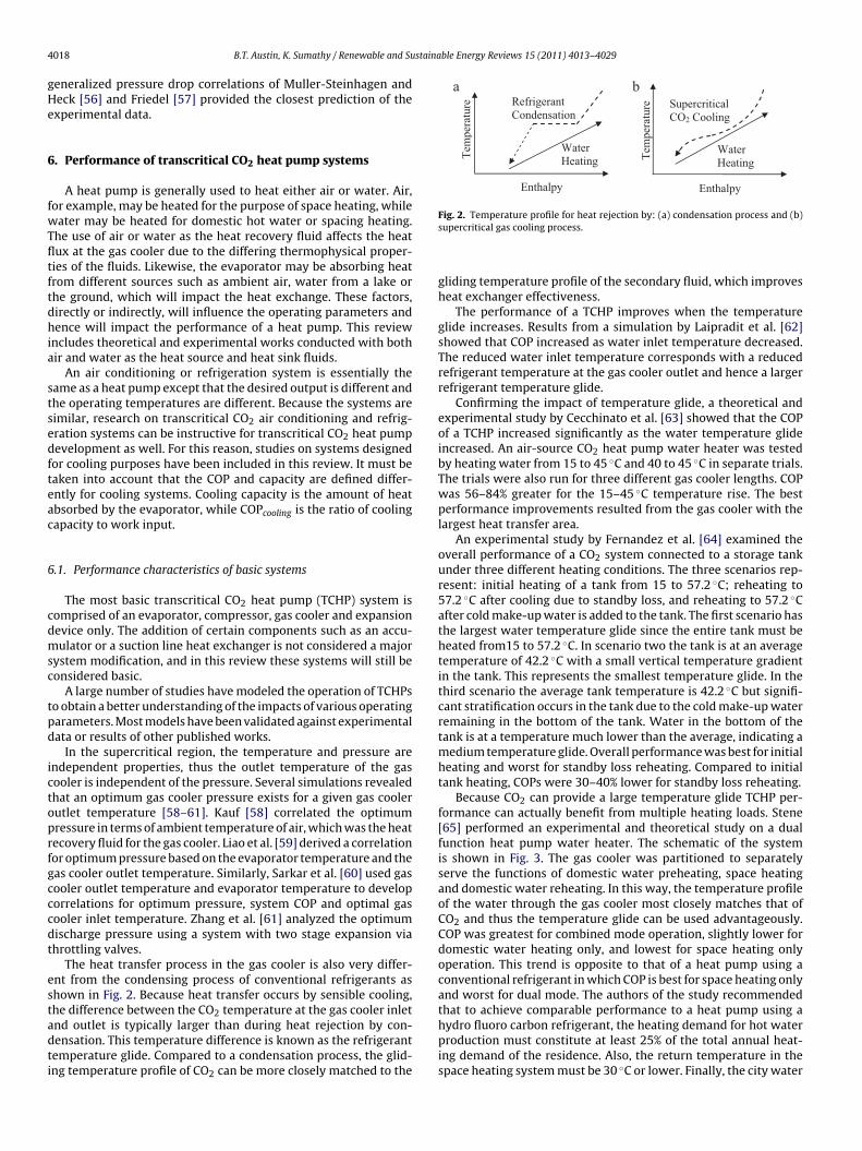
4 stainable Energy Reviews 15 (2011) 4013–4029
gHe
6
fwTfltftdhia
stsedfteac
6
cdmsc
tpd
ictoprfgcccdt
estadti
Tem
pera
ture
Supercritical CO2 Cooling
Water Heating
Enthalpy
Tem
pera
ture
Water Heating
Refrigerant a b
Condensation
Enthalpy
Fig. 2. Temperature profile for heat rejection by: (a) condensation process and (b)
018 B.T. Austin, K. Sumathy / Renewable and Su
eneralized pressure drop correlations of Muller-Steinhagen andeck [56] and Friedel [57] provided the closest prediction of thexperimental data.
. Performance of transcritical CO2 heat pump systems
A heat pump is generally used to heat either air or water. Air,or example, may be heated for the purpose of space heating, whileater may be heated for domestic hot water or spacing heating.
he use of air or water as the heat recovery fluid affects the heatux at the gas cooler due to the differing thermophysical proper-ies of the fluids. Likewise, the evaporator may be absorbing heatrom different sources such as ambient air, water from a lake orhe ground, which will impact the heat exchange. These factors,irectly or indirectly, will influence the operating parameters andence will impact the performance of a heat pump. This review
ncludes theoretical and experimental works conducted with bothir and water as the heat source and heat sink fluids.
An air conditioning or refrigeration system is essentially theame as a heat pump except that the desired output is different andhe operating temperatures are different. Because the systems areimilar, research on transcritical CO2 air conditioning and refrig-ration systems can be instructive for transcritical CO2 heat pumpevelopment as well. For this reason, studies on systems designedor cooling purposes have been included in this review. It must beaken into account that the COP and capacity are defined differ-ntly for cooling systems. Cooling capacity is the amount of heatbsorbed by the evaporator, while COPcooling is the ratio of coolingapacity to work input.
.1. Performance characteristics of basic systems
The most basic transcritical CO2 heat pump (TCHP) system isomprised of an evaporator, compressor, gas cooler and expansionevice only. The addition of certain components such as an accu-ulator or a suction line heat exchanger is not considered a major
ystem modification, and in this review these systems will still beonsidered basic.
A large number of studies have modeled the operation of TCHPso obtain a better understanding of the impacts of various operatingarameters. Most models have been validated against experimentalata or results of other published works.
In the supercritical region, the temperature and pressure arendependent properties, thus the outlet temperature of the gasooler is independent of the pressure. Several simulations revealedhat an optimum gas cooler pressure exists for a given gas coolerutlet temperature [58–61]. Kauf [58] correlated the optimumressure in terms of ambient temperature of air, which was the heatecovery fluid for the gas cooler. Liao et al. [59] derived a correlationor optimum pressure based on the evaporator temperature and theas cooler outlet temperature. Similarly, Sarkar et al. [60] used gasooler outlet temperature and evaporator temperature to developorrelations for optimum pressure, system COP and optimal gasooler inlet temperature. Zhang et al. [61] analyzed the optimumischarge pressure using a system with two stage expansion viahrottling valves.
The heat transfer process in the gas cooler is also very differ-nt from the condensing process of conventional refrigerants ashown in Fig. 2. Because heat transfer occurs by sensible cooling,he difference between the CO2 temperature at the gas cooler inlet
nd outlet is typically larger than during heat rejection by con-ensation. This temperature difference is known as the refrigerantemperature glide. Compared to a condensation process, the glid-ng temperature profile of CO2 can be more closely matched to thesupercritical gas cooling process.
gliding temperature profile of the secondary fluid, which improvesheat exchanger effectiveness.
The performance of a TCHP improves when the temperatureglide increases. Results from a simulation by Laipradit et al. [62]showed that COP increased as water inlet temperature decreased.The reduced water inlet temperature corresponds with a reducedrefrigerant temperature at the gas cooler outlet and hence a largerrefrigerant temperature glide.
Confirming the impact of temperature glide, a theoretical andexperimental study by Cecchinato et al. [63] showed that the COPof a TCHP increased significantly as the water temperature glideincreased. An air-source CO2 heat pump water heater was testedby heating water from 15 to 45 ◦C and 40 to 45 ◦C in separate trials.The trials were also run for three different gas cooler lengths. COPwas 56–84% greater for the 15–45 ◦C temperature rise. The bestperformance improvements resulted from the gas cooler with thelargest heat transfer area.
An experimental study by Fernandez et al. [64] examined theoverall performance of a CO2 system connected to a storage tankunder three different heating conditions. The three scenarios rep-resent: initial heating of a tank from 15 to 57.2 ◦C; reheating to57.2 ◦C after cooling due to standby loss, and reheating to 57.2 ◦Cafter cold make-up water is added to the tank. The first scenario hasthe largest water temperature glide since the entire tank must beheated from15 to 57.2 ◦C. In scenario two the tank is at an averagetemperature of 42.2 ◦C with a small vertical temperature gradientin the tank. This represents the smallest temperature glide. In thethird scenario the average tank temperature is 42.2 ◦C but signifi-cant stratification occurs in the tank due to the cold make-up waterremaining in the bottom of the tank. Water in the bottom of thetank is at a temperature much lower than the average, indicating amedium temperature glide. Overall performance was best for initialheating and worst for standby loss reheating. Compared to initialtank heating, COPs were 30–40% lower for standby loss reheating.
Because CO2 can provide a large temperature glide TCHP per-formance can actually benefit from multiple heating loads. Stene[65] performed an experimental and theoretical study on a dualfunction heat pump water heater. The schematic of the systemis shown in Fig. 3. The gas cooler was partitioned to separatelyserve the functions of domestic water preheating, space heatingand domestic water reheating. In this way, the temperature profileof the water through the gas cooler most closely matches that ofCO2 and thus the temperature glide can be used advantageously.COP was greatest for combined mode operation, slightly lower fordomestic water heating only, and lowest for space heating onlyoperation. This trend is opposite to that of a heat pump using aconventional refrigerant in which COP is best for space heating onlyand worst for dual mode. The authors of the study recommendedthat to achieve comparable performance to a heat pump using ahydro fluoro carbon refrigerant, the heating demand for hot water
production must constitute at least 25% of the total annual heat-ing demand of the residence. Also, the return temperature in thespace heating system must be 30 ◦C or lower. Finally, the city water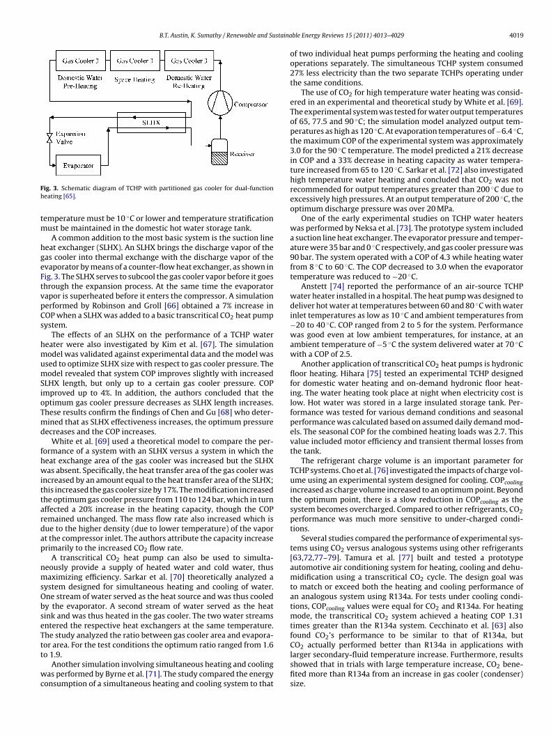
B.T. Austin, K. Sumathy / Renewable and Sustaina
Fh
tm
hgeFtvpCs
hmumSioTmd
fhwittardap
nmsObseTtt
wc
ig. 3. Schematic diagram of TCHP with partitioned gas cooler for dual-functioneating [65].
emperature must be 10 ◦C or lower and temperature stratificationust be maintained in the domestic hot water storage tank.A common addition to the most basic system is the suction line
eat exchanger (SLHX). An SLHX brings the discharge vapor of theas cooler into thermal exchange with the discharge vapor of thevaporator by means of a counter-flow heat exchanger, as shown inig. 3. The SLHX serves to subcool the gas cooler vapor before it goeshrough the expansion process. At the same time the evaporatorapor is superheated before it enters the compressor. A simulationerformed by Robinson and Groll [66] obtained a 7% increase inOP when a SLHX was added to a basic transcritical CO2 heat pumpystem.
The effects of an SLHX on the performance of a TCHP watereater were also investigated by Kim et al. [67]. The simulationodel was validated against experimental data and the model was
sed to optimize SLHX size with respect to gas cooler pressure. Theodel revealed that system COP improves slightly with increased
LHX length, but only up to a certain gas cooler pressure. COPmproved up to 4%. In addition, the authors concluded that theptimum gas cooler pressure decreases as SLHX length increases.hese results confirm the findings of Chen and Gu [68] who deter-ined that as SLHX effectiveness increases, the optimum pressure
ecreases and the COP increases.White et al. [69] used a theoretical model to compare the per-
ormance of a system with an SLHX versus a system in which theeat exchange area of the gas cooler was increased but the SLHXas absent. Specifically, the heat transfer area of the gas cooler was
ncreased by an amount equal to the heat transfer area of the SLHX;his increased the gas cooler size by 17%. The modification increasedhe optimum gas cooler pressure from 110 to 124 bar, which in turnffected a 20% increase in the heating capacity, though the COPemained unchanged. The mass flow rate also increased which isue to the higher density (due to lower temperature) of the vaport the compressor inlet. The authors attribute the capacity increaserimarily to the increased CO2 flow rate.
A transcritical CO2 heat pump can also be used to simulta-eously provide a supply of heated water and cold water, thusaximizing efficiency. Sarkar et al. [70] theoretically analyzed a
ystem designed for simultaneous heating and cooling of water.ne stream of water served as the heat source and was thus cooledy the evaporator. A second stream of water served as the heatink and was thus heated in the gas cooler. The two water streamsntered the respective heat exchangers at the same temperature.he study analyzed the ratio between gas cooler area and evapora-or area. For the test conditions the optimum ratio ranged from 1.6
o 1.9.Another simulation involving simultaneous heating and coolingas performed by Byrne et al. [71]. The study compared the energy
onsumption of a simultaneous heating and cooling system to that
ble Energy Reviews 15 (2011) 4013–4029 4019
of two individual heat pumps performing the heating and coolingoperations separately. The simultaneous TCHP system consumed27% less electricity than the two separate TCHPs operating underthe same conditions.
The use of CO2 for high temperature water heating was consid-ered in an experimental and theoretical study by White et al. [69].The experimental system was tested for water output temperaturesof 65, 77.5 and 90 ◦C; the simulation model analyzed output tem-peratures as high as 120 ◦C. At evaporation temperatures of −6.4 ◦C,the maximum COP of the experimental system was approximately3.0 for the 90 ◦C temperature. The model predicted a 21% decreasein COP and a 33% decrease in heating capacity as water tempera-ture increased from 65 to 120 ◦C. Sarkar et al. [72] also investigatedhigh temperature water heating and concluded that CO2 was notrecommended for output temperatures greater than 200 ◦C due toexcessively high pressures. At an output temperature of 200 ◦C, theoptimum discharge pressure was over 20 MPa.
One of the early experimental studies on TCHP water heaterswas performed by Neksa et al. [73]. The prototype system includeda suction line heat exchanger. The evaporator pressure and temper-ature were 35 bar and 0 ◦C respectively, and gas cooler pressure was90 bar. The system operated with a COP of 4.3 while heating waterfrom 8 ◦C to 60 ◦C. The COP decreased to 3.0 when the evaporatortemperature was reduced to −20 ◦C.
Anstett [74] reported the performance of an air-source TCHPwater heater installed in a hospital. The heat pump was designed todeliver hot water at temperatures between 60 and 80 ◦C with waterinlet temperatures as low as 10 ◦C and ambient temperatures from−20 to 40 ◦C. COP ranged from 2 to 5 for the system. Performancewas good even at low ambient temperatures, for instance, at anambient temperature of −5 ◦C the system delivered water at 70 ◦Cwith a COP of 2.5.
Another application of transcritical CO2 heat pumps is hydronicfloor heating. Hihara [75] tested an experimental TCHP designedfor domestic water heating and on-demand hydronic floor heat-ing. The water heating took place at night when electricity cost islow. Hot water was stored in a large insulated storage tank. Per-formance was tested for various demand conditions and seasonalperformance was calculated based on assumed daily demand mod-els. The seasonal COP for the combined heating loads was 2.7. Thisvalue included motor efficiency and transient thermal losses fromthe tank.
The refrigerant charge volume is an important parameter forTCHP systems. Cho et al. [76] investigated the impacts of charge vol-ume using an experimental system designed for cooling. COPcoolingincreased as charge volume increased to an optimum point. Beyondthe optimum point, there is a slow reduction in COPcooling as thesystem becomes overcharged. Compared to other refrigerants, CO2performance was much more sensitive to under-charged condi-tions.
Several studies compared the performance of experimental sys-tems using CO2 versus analogous systems using other refrigerants[63,72,77–79]. Tamura et al. [77] built and tested a prototypeautomotive air conditioning system for heating, cooling and dehu-midification using a transcritical CO2 cycle. The design goal wasto match or exceed both the heating and cooling performance ofan analogous system using R134a. For tests under cooling condi-tions, COPcooling values were equal for CO2 and R134a. For heatingmode, the transcritical CO2 system achieved a heating COP 1.31times greater than the R134a system. Cecchinato et al. [63] alsofound CO2’s performance to be similar to that of R134a, butCO2 actually performed better than R134a in applications with
larger secondary-fluid temperature increase. Furthermore, resultsshowed that in trials with large temperature increase, CO2 bene-fited more than R134a from an increase in gas cooler (condenser)size.
4 staina
osfhiadst
6
gilom
ptapTieoeIt
efestf
icmcoc
6
nTeisetwac
o[aaoto
020 B.T. Austin, K. Sumathy / Renewable and Su
The performance of a system using R410A was compared to thatf a transcritical CO2 system by Richter et al. [78]. The air-to-airystems were tested for different ambient conditions. COP valuesor the CO2 system were generally lower than the R410A system;owever, heating capacity was greater for CO2 under most operat-
ng temperatures. One significant finding of the study was that asmbient temperature decreased, the heating capacity of the TCHPecreased marginally compared to the R410A system. Thus CO2ystems would require less supplemental heat at lower ambientemperatures.
.2. Component and system modifications
The improvement of overall cycle performance in a TCHPenerally requires consideration of the system as a whole. Thenteractions between the components do not always allow for iso-ated improvements to a single component. Still, each componentr process in the cycle plays a role in dictating the overall perfor-ance of the system.Analysis the exergetic efficiency (2nd law efficiency) of TCHP
rovides insight as to which components hold the greatest poten-ial for overall improvements of cycle performance. A theoreticalnalysis of 2nd law efficiencies by Robinson and Groll [66] com-ared the component irreversibilities (exergy losses) in a basicCHP. The study showed that the expansion valve suffers the mostrreversibilities followed in order by the compressor, gas cooler andvaporator. Yang et al. [80] also found that the most exergy lossccurred in the expansion valve, but concluded that the next great-st contribution to exergy loss depended on operating conditions.n some cases the losses of the gas cooler were greater than that ofhe compressor. In other cases the trend was reversed.
In contrast to Robinson and Groll [66] and Yang et al. [80], Sarkart al. [81] concluded that the compressor had greatest exergy loss,ollowed in order by the gas cooler, evaporator and finally thexpansion valve. The model of Sarkar et al. [81] was designed forimultaneous heating and cooling and included the effects of heatransfer and fluid flow. These factors may have led to the differencesrom the other studies.
Each process in the cycle can be modified in a variety of waysn the attempt to improve overall performance. Some modifi-ations make isolated alterations of only one component. Otherodifications are more closely tied to the interaction of system
omponents. These changes may require the alteration more thanne component. Sections 6.2.1–6.2.3 will address the possible pro-ess modifications which may lead to cycle improvements.
.2.1. Heat exchanger modificationsImprovements to the gas cooler and the evaporator can sig-
ificantly impact the performance and application potential ofCHPs. Pettersen et al. [82] reviewed unique characteristics of heatxchangers used for CO2 in evaporators and gas coolers. By increas-ng the contact area between the refrigerant and the heat exchangerurface, microchannel tubes can reduce the overall size of a heatxchanger for a given heating or cooling capacity. The automo-ive market in particular would benefit from the reduced size andeight of micro-channel heat exchangers. Microchannel tubes are
lso capable of withstanding high working pressures, making themompatible with CO2 systems.
The design of a gas cooler is strongly dependant on the sec-ndary fluid used and the flow characteristics. Fronk and Garimella83] drew attention to the importance of the ratio between CO2nd secondary fluid heat transfer coefficients. Generally hair < hCO2
nd hwater > hCO2 . Therefore in a water coupled heat exchanger theverall heat transfer coefficient is more sensitive to the CO2 heatransfer coefficient; hCO2 is the primary factor which determinesverall heat transfer coefficient. In an air coupled heat exchangerble Energy Reviews 15 (2011) 4013–4029
the overall heat transfer coefficient is more sensitive to the heattransfer coefficient of air; hair dominates the overall heat transfercoefficient.
Gas cooler performance improves when the temperature dif-ference between CO2 and the heat recovery fluid (air or water) atany point in the gas cooler is reduced. Sarkar et al. [60,81] analyzedthe irreversibilities of the gas cooler and concluded that approxi-mately 90% of the heat exchanger losses were due to temperaturedifferences between the refrigerant and the secondary fluid. Irre-versibilities due to pressure drop in the gas cooler were negligiblein comparison.
In a counter-flow gas cooler, the difference between the CO2inlet temperature and the secondary fluid outlet temperature isknown as the hot-side approach temperature difference (�Tap).Cold-side �Tap is the difference between CO2 outlet temperatureand secondary fluid inlet temperature. Fronk and Garimella [83,84]showed that as the cold-side �Tap is reduced, the optimum gascooler pressure is reduced. This leads to a reduction in compressorwork.
Losses due to temperature difference can be reduced by increas-ing heat transfer area, but there is a limit to the effectivenessof this approach. A theoretical optimization of tube-in-tube heatexchanger geometry was performed by Sarkar et al. [85] based onminimizing irreversibility. The study showed that for a given set ofoperating conditions, a heat exchanger has an optimum capacityfor a given diameter and length of the refrigerant tube. Below theoptimum diameter, increased pressure drop leads to greater vis-cous losses. Increasing the diameter decreases the pressure dropbut increases the thermal dissipation due to reduced heat transfercoefficient. Thermal dissipation can be reduced by increasing tubelength, but this in turn leads to increased pressure drop. Hence anoptimum set of dimensions exist which will provide the greatestheat transfer capacity.
Shell and tube heat exchangers for use with CO2 were theo-retically analyzed by Hwang and Radermacher [86]. Three shelland tube heat exchanger designs were modeled for gas coolingand evaporation processes. For each heat exchanger the perfor-mance and the component mass was compared to conventionalR22 heat exchangers. The CO2 gas cooler could achieve an equiv-alent capacity to the R22 condenser while reducing the mass byabout 50%.
Experimental and theoretical studies by Fronk and Garimella[83,84] investigated a water-coupled gas cooler with serpentinepattern microchannel tubes. Water flowed through plate-typeheat exchangers with internal fins, while CO2 passed through themicrochannels in a cross-counter-flow arrangement. The config-uration facilitated the required heat capacity in a more compactsize.
Air-coupled CO2 gas coolers were also investigated [87–89].Hwang et al. [87] tested the performance of a fin and tube gas coolerunder various operating conditions. The test parameters were airinlet temperature, air velocity, refrigerant flow rate and gas coolerpressure. A series of twelve parametric tests were conducted as afirst step in establishing a performance database.
A microchannel gas cooler was modeled by Yin et al. [88]. Inthe model, CO2 flowed through microchannel tube-banks, while airwas maintained in cross-flow conditions. Each tube bank consistedof ten or more parallel microchannel tubes connected to a header ateach end. As a baseline a single tube-bank was tested. Two config-urations were tested: in the first test, additional tube-banks wereadded in the plane perpendicular to the air flow (thus increasing thefrontal area of the heat exchanger); in the second test, tube-banks
were aligned in the direction the air flow, one behind the other, asshown in Fig. 4. In the first test, the model showed an increase inheating capacity from one to three sets of tube-banks. More thanthree tub-banks produced marginal increase in heat capacity. In
B.T. Austin, K. Sumathy / Renewable and Sustainable Energy Reviews 15 (2011) 4013–4029 4021
CO2 Inlet
CO2 Outlet
Air flow
CO2 Inlet
CO2 Outlet
Air flow
CO2 Inlet
Air flow
gurations for microchannel gas cooler [88].
td
caTupcattats
mdopotaattimitt
a[mttCsme
hoeubdua
Air flow
Air flow
Slab 1
Slab 1
Slab 2
Slab 2
Air flow
An indirect modification of the evaporation process is the addi-tion of a flash gas bypass (FGB) system. Fig. 6 shows the schematicdiagram of a TCHP with FGB. In a FGB arrangement, the refrigerant
Fig. 4. Heat exchanger tube-bank confi
he second test, increasing the number of tube banks resulted in aecreased �Tap and an increased heating capacity.
Neksa et al. [89] proposed a novel TCHP system in which the gasooler rejects heat to air driven by natural convection instead offan. Both experimental and simulation studies were conducted.
he counter flow gas cooler consisted of vertical aluminum fins forpward air flow bonded to vertical refrigerant tubes with high tem-erature CO2 entering at the top. The experimental setup achievedold-end �Tap from 2.6 to 10.8 ◦C and a heat output between 71nd 140 W for different operating conditions. Further experimen-ation investigated the effects of an extended “chimney” attachedo the top of the heat exchanger. This modification increased their flow rate and the heat output. The simulation model was usedo optimize fin spacing, thickness and height and to analyze otherystem modifications.
Research has also been conducted to investigate heat exchangerodifications for use in CO2 evaporators. Bendaoud et al. [90]
eveloped a model for the purpose of analyzing the performancef finned tube evaporators with CO2. The model showed that theressure drop of CO2 through the evaporator is less than withther refrigerants. The use of a microchannel heat exchanger ashe evaporator has also been shown to improve the performance ofTCHP system. Yun et al. [91] used a numerical model to comparemicrochannel evaporator for air conditioning with a conven-
ional fin-and-tube evaporator. The model was validated againsthe results of an experimental system using R134a and also val-dated against the results of a study by Beaver et al. [92]. The
icrochannel evaporator had a 33% greater heat transfer capac-ty. Compared to the conventional heat exchanger, the capacity ofhe microchannel heat exchanger was more strongly dependant onube width, tube pitch and fin spacing.
Other authors have also developed models for the purpose ofnalyzing microchannel evaporators using CO2. Kim and Bullard93] developed a model to analyze the performance of a two-slab
icrochannel evaporator. The model incorporated existing correla-ions for heat transfer coefficient and pressure drop and can be usedo aid in designing compact microchannel evaporators for use withO2. Jin et al. [94] developed their model using new correlationspecifically developed for CO2. The model was validated experi-entally and was shown to be applicable for systems with high or
ven superheated vapor quality.CO2 is well suited for use with microchannel tubes because its
igh working pressure and high vapor density reduce the problemf phase maldistribution experienced by other refrigerants. Brixt al. performed a modeling study to analyze the effects of non-niform CO2 distribution [95]. CO2 maldistribution is considered
oth due to non-uniform airflow and due to non-uniform phaseistribution in the channels. For horizontal flow of refrigerant,neven airflow distribution and non-uniform refrigerant qualityt the inlet both caused reduction in the evaporator capacity. ForFig. 5. Heat exchanger slab configurations for microchannel evaporator [91].
vertical upward flow, airflow maldistribution caused capacityreduction, but refrigerant phase distribution did not impact thecapacity. The authors note that for a system with more than twochannels the results may prove different.
The alignment and orientation of the evaporator slabs alsoimpacts the performance of a CO2 evaporator. A simulation by Yunet al. [91] compared the performance of two cross-flow evaporatorconfigurations using CO2 as the refrigerant and air as the secondaryfluid. Fig. 5 shows the two arrangements. Two slabs of microchanneltubes arranged in a V-shape showed better heat transfer capacitythan two slabs arranged in series with respect to airflow.
Fig. 6. Schematic diagram of TCHP with flash gas bypass [96].

4 stainable Energy Reviews 15 (2011) 4013–4029
eslTtbosbi
tmt
6
otstctucmb
prtcrrs
aocbeet2fo
Gas Cooler
Evaporator
H.P. Comp.
L.P. Comp.
Exp. Valve
Intercooler
SLHX
022 B.T. Austin, K. Sumathy / Renewable and Su
xpands through a single throttling device to the evaporator pres-ure and then enters a flash tank. From the flash tank only saturatediquid enters the evaporator while vapor bypasses the evaporator.he evaporation process is impacted because the vapor quality athe evaporator inlet is significantly reduced. An experimental studyy Elbel and Hrnjak [96] showed that FGB increased the CO2 evap-rator’s heat transfer capacity up to 9%, and COPcooling of the TCHPystem improved up to 7%. The improved performance can mainlye attributed to reduced pressure drop through the evaporator and
ncreased heat transfer coefficient in the evaporator.In the same study, Elbel and Hrnjak [96] also investigated
he impacts of a FGB arrangement on the CO2 distribution in aicrochannel evaporator. FGB led to more uniform refrigerant dis-
ribution in the evaporator.
.2.2. Compression process modificationsEfficiency of a TCHP can be improved by various modifications
f the compression process. The most basic compressor modifica-ion is two-stage compression. By separating compression into twotages, each compressor will have a lower pressure ratio which inurn improves the isentropic efficiency. Further improvements inycle efficiency can be obtained by cooling the refrigerant betweenhe compression stages. Cecchinato et al. [97] showed that these of intercooling in a transcritical CO2 system with two-stageompression led to improved cycle efficiency. There are variousethods of intercooling, and multi-stage compression systems can
e configured in different ways as will be discussed in below.A theoretical study by Cecchinato et al. [97] analyzed the
erformance of transcritical CO2 air conditioning system incorpo-ating dual compression with intercooling (DCWI). Fig. 7 showshe system configuration. Compared to a system using single-stageompression, DCWI improved the COPcooling 9%. At lower evapo-ator temperatures, COPcooling gains were more substantial. Theesults also showed that the benefits of inter stage cooling aretrongly enhanced by the use of a suction line heat exchanger.
A common method of intercooling is to reject heat to ambientir by means of a heat exchanger. Cecchinato et al. [97] pointedut that due to the higher temperatures involved in the trans-ritical cycle, CO2 is better able to take advantage of intercoolingy rejecting heat to the environment than conventional refrig-rants. Cavallini et al. [7] tested the cooling performance of anxperimental system incorporating DCWI at different intercooler
emperatures. The COPcooling at optimum discharge pressures was.1 for the 20.5 and 21.5 ◦C intercooler temperatures and 1.8or the 33.0 ◦C temperature. A simulation model was also devel-ped in order to analyze three modifications to the two-stageFig. 8. TCHP with flash intercooling: (a) schemat
Fig. 7. TCHP with dual-compression and intercooling [97].
compression system. The addition of a SLHX provided a 7.6%improvement in COPcooling. Incorporating two-stage throttlingimproved the COPcooling by 21.1%. Including both of these modifi-cations increased the COPcooling by 24.0% above that of the baselinesystem.
Beyond DCWI, various systems can be configured which inte-grate modifications of both the expansion and compressionprocesses. Flash intercooling is an alternative means of cooling therefrigerant between compression stages in which the inter-stageCO2 temperature is reduced by mixing with expansion vapor ina flash tank. Fig. 8 shows the system schematic and cycle dia-gram of a TCHP incorporating flash intercooling. Agrawal andBhattacharyya [98] determined that, unlike other methods of inter-cooling, two-stage compression with flash intercooling decreasedthe COP compared to that of an analogous system with single stagecompression. This is due to the fact that mass flow rate throughthe second stage compressor increases significantly. Though thespecific work of compression in the second stage is reduced, actualcompression work in the second stage increases. Intermediate pres-sure was found to have little impact on COP.
Another modification is the use of an economizer tank, whichis similar to the flash gas bypass system discussed in Section 6.2.1.Economizer systems in various configurations have been studiedby several researchers [97,99–101]. Cho et al. [99] obtained anincrease in COPcooling up to 16.5% by the addition of an economizerto an experimental dual compression transcritical CO system.
2Cecchinato et al. [97] theoretically analyzed a similar system whichresulted in a COPcooling increase of 16.8–28.7% compared to a sys-tem using single compression. Sarkar and Agrawal [100] tested aic diagram and (b) cycle P–h diagram [98].

B.T. Austin, K. Sumathy / Renewable and Sustainable Energy Reviews 15 (2011) 4013–4029 4023
pi
icpcswmopth
ent7aau
tticw
F
Gas Cooler
Evaporator
Aux. Comp.
L.P. Comp.
Internal Heat Exchanger
Fig. 9. Reciprocating piston compressor with Voorhees modification [101].
arallel compression system with an economizer. The COPcoolingmproved by 47.3% over a conventional transcritical system.
Zha et al. [101] tested an experimental laboratory setup whichncluded a flash economizer and a single-stage reciprocating pistonompressor with a Voorhees-type modification. In a Voorhees com-ressor, intermediate pressure CO2 is injected into the compressionhamber during only a portion of the intake stroke. The compres-or modification is shown in Fig. 9. The Voorhees-economizer cycleas compared to a single stage compression cycle without econo-ization. The economizer-cycle increased heating capacity for all
perating conditions; however, COP improved only for low com-ressor speeds and low evaporator temperatures. At an evaporatoremperature of −20 ◦C, the economizer provided nearly double theeating capacity.
A dual compression-dual expansion system with internal heatxchanger was experimentally tested for water heating by Fer-andez et al. [64]. The performance was compared to a systemhat used only dual compression with intercooling. COP improved.5% for the test with a small increase in water temperature andn ambient temperature of 10 ◦C. At higher ambient temperaturesnd for larger temperature glide requirements, COP was virtuallynchanged or actually decreased.
Cecchinato et al. [97] theoretically studied a system similaro Fernandez et al. [64] with the addition of a SLHX prior tohe low pressure compressor, see Fig. 10. The other distinction
s that the simulation was performed for cooling. The study con-luded that COPcooling improved 15.6% compared to a DCWI systemith an evaporator temperature of −30 ◦C. Furthermore COPcoolingGas Cooler
H.P.Comp.
L.P.Comp.
Intercooler
EvaporatorLow Pressure SLHX
HighPressure
SLHX
ig. 10. Schematic diagram of a dual-compression dual-expansion system [97].
Fig. 11. Schematic diagram of an auxiliary loop TCHP system [97].
improved 20.6–29.3% for all conditions compared to a single com-pression system.
A transcritical system very unlike those of the previous studieswas theoretically analyzed by Cecchinato et al. [97]. The system wascomposed of two separate heat pump loops with independent com-pressors. An internal heat exchanger served as the evaporator in theauxiliary loop while also subcooling the main-loop refrigerant priorto expansion. The system is represented in Fig. 11. Compared to heatpumps with more complex dual compression cycles, the auxiliarycycle’s cooling performance was better only for low intermediatepressures.
6.2.3. Expansion process modificationsThe two functions of the expansion device are to maintain the
pressure difference between the gas cooler and the evaporatorand to maintain proper flow of distribution to the evaporator. Asdiscussed in Section 6.1, optimum system performance requiresmaintaining the optimum pressure in the gas cooler, therefore theexpansion device plays an important role efficient system opera-tion. An experimental study by Aprea and Maiorino [102] examineda method of maintaining the optimum high side pressure by two-stage expansion under changing ambient temperatures. The testsetup incorporated a pressure valve and an electronically con-trolled expansion valve.
6.2.3.1. Capillary tube expansion. The primary means of expansioncontrol for experimental transcritical CO2 heat pump systems isthrough an expansion valve. Small refrigeration and heat pumpunits using conventional refrigerants commonly incorporate cap-illary tubes for expansion control, but there has been uncertaintyabout the effectiveness of capillary tubes in transcritical CO2 sys-tems. In order to ensure that a capillary tube can maintain theoptimum gas cooler pressure and achieve optimal overall systemperformance theoretical studies have been conducted [103–109].The studies generally indicate capillary tubes can perform ade-quately in TCHPs.
Agrawal and Bhattacharyya [103–105] performed a series ofnumerical studies on the flow characteristics of CO2 in adiabaticcapillary tubes and the performance of TCHP systems incorporat-ing capillary expansion control. In one study [103] a capillary tubewas used in a system designed for simultaneous heating and cool-ing. Performance was compared to a system studied by Sarkar et al.[70] which used a controllable expansion valve. Capillary lengthhad significant influence on the gas cooler pressure and on the sys-
tem COP. With optimal capillary length the system was tested fora range of gas cooler exit temperatures. The optimized capillarytube was able to very closely match the optimal gas cooler pres-sure calculated using the expansion valve. The COP for capillary
4024 B.T. Austin, K. Sumathy / Renewable and Sustainable Energy Reviews 15 (2011) 4013–4029
Lin Lheat exchange Lout
From gas cooler
To evaporator
To compressor
Super-critical flow
Subcritical2-phase
flow
Solder joint
Trans-criticalflow
Capillary Tube
From evaporator
Suction line
acld
iaccEd
ltsmvAa
tciniaovGfltfd
acaet(mr
6ibhaga
Table 1Theoretical COPcooling of transcritical CO2 system and subcritical R22 system bothincorporating expanders of various isentropic efficiencies [79].
Expanderefficiency (%)
COPcooling atTambient = 28 ◦C
COPcooling atTambient = 50 ◦C
CO2 R22 CO2 R22
100 6.9–7.6 5.8 2.9–3.0 3.380 6.4–7.0 5.8 2.5–2.6 3.2
Fig. 12. Section of a non-adiabatic capillary tube heat exchanger [108].
nd expansion valve systems were nearly the same and coolingapacity of the capillary system was slightly better. Optimal capil-ary tube length was found to be strongly dependant on capillaryiameter and surface roughness.
Exergetic efficiency of a transcritical CO2 system using a cap-llary tube for expansion control was also examined by Agrawalnd Bhattacharyya [104]. The exergy efficiency of a TCHP with aapillary tube was 13–19% greater than that of a system using aontrollable expansion valve operating with the same conditions.xergy efficiency decreased under conditions of increased capillaryiameter or conditions of increased capillary length.
Madsen et al. [106] also considered the performance of a capil-ary tube in a transcritical CO2 cycle. A capillary tube was comparedo a fixed pressure valve and an adjustable (optimized) expan-ion valve. Simulation was based on a constant enthalpy expansionodel. Capillary performance was superior to the fixed pressure
alve but the adjustable expansion valve produced the best COP.uthors concluded that for a small system, a capillary tube can becompetitive solution for expansion control.
In addition to adiabatic capillary tubes, non-adiabatic capillaryubes have been investigated as well [107–109]. In a non-adiabaticapillary tube, refrigerant will reject heat to the environment dur-ng the expansion in the tube. However, the heat rejected from aon-adiabatic capillary could be utilized as useful heat. As shown
n Fig. 12, the capillary can serve as a heat exchanger by solderingportion of the capillary to the refrigerant line between the evap-rator outlet and the compressor inlet. This provides superheatedapor to the compressor in the same way as an SLHX. Chen andu [107] analyzed this type of system using used a non-adiabaticow model to examine heat exchange and flow characteristics of aranscritical CO2 capillary tube. Cooling capacity of the system wasound to decrease as capillary length increased for a given inneriameter and pressure.
Non-adiabatic capillary tubes were also investigated by Agrawalnd Bhattacharyya [108,109]. Flow characteristics, heat transferharacteristics and system performance were analyzed. Particularttention was paid to the effect of gas cooler outlet temperature,vaporator temperature and placement of the heat exchange por-ion of the tube relative to the flow condition of CO2 in the tubesuper critical, transcritical, or two-phase subcritical). It was recom-
ended that the heat exchange take place through the two-phaseegion of the capillary.
.2.3.2. Expansion work recovery. Using an expansion valve or cap-llary tube results in an energy loss because no useful work is doney the expansion process. These expansion losses associated with
eat pumps using conventional refrigerants are generally small. Intranscritical CO2 cycle, the greater pressure difference results inreater expansion losses, thus making work recovery more feasiblend more beneficial. A theoretical investigation by Yang et al. [80]60 5.9–6.5 5.7 2.2–2.3 3.10 4.8–5.3 5.5 1.6 2.8
determined that the use of an expander in place of a conventionalexpansion valve produced a 50% decrease in exergy loss, resultingin a 30% improvement in system exergy efficiency. The expanderreduced the optimum gas cooler pressure and led to a 33% higherCOPcooling.
There are many devices which can potentially be used asexpanders for the purpose of work recovery in a TCHP. In additionto turbines, expander types include rotary, reciprocating, scroll,screw, and vane. Each design has its advantages and limitations.Experimental and theoretical research has been conducted on awide variety of systems.
Huff and Radermacher [79] carried out a theoretical study whichcompared the performance of reciprocating piston, rotary pis-ton, and scroll expander/compressor pairs in a transcritical CO2cooling system. Each setup paired the same type of compressorand expander. The simulation modeled valve losses, internal leak-age, internal heat transfer and unmatched volume ratio. Resultsindicated that the reciprocating and rotary piston expanders hadsimilar performance, but the scroll expander performed poorlywhen leakage gaps were larger than 5 �m. The simulation also eval-uated the performance of a CO2 system with expander relative to asystem using R22 with expander and with expansion valve. Table 1compares the performance at ambient temperatures of 28 ◦C and50 ◦C and expander efficiencies of 100%, 80%, 60%, and 0%. The CO2system generally performed better than the R22 system for lowerambient temperatures.
A numerical simulation of a CO2 transcritical cooling cycle witha scroll type expander was performed by Kim et al. [110]. The sys-tem incorporated two-stage compression with intercooling usingscroll compressors. The expander shaft was directly coupled to thefirst stage compressor. The model accounted for leakage by assum-ing a scroll clearance of 8 �m. At a gas cooler exit temperatureof 35 ◦C and compressor inlet and outlet pressures of 35 bar and100 bar respectively, the total efficiency of the expander was 54.4%.The expander efficiency was relatively stable for changing pres-sure ratios, however, the compressor efficiency decreased as inletpressure increased. The expander reduced the required externalcompressor work by about 12%. This resulted in an increase in thecooling capacity of 8.6% and an increase in COPcooling of 23.5%.
Baek et al. [111] designed, built and tested an early prototype ofa two-cylinder reciprocating piston work recovery expander for usewith CO2 under cooling conditions. Being a prototype, the systemwas not optimized and COPcooling values were actually less than one.Only one test condition included a supercritical pressure. For thetranscritical test condition, the isentropic efficiency of the expanderwas 10.27%, and the expander improved the COPcooling 6.6% com-pared to the system using an expansion valve. A simulation modelwas also developed for the system [112]. The predicted exhaustpressure was significantly higher than measured in the experi-ments. This was attributed to a significant portion of CO2 leakingfrom the cylinder via the piston ring in the experimental prototype.
A reciprocating piston expander was also tested by Nickl et al.[113]. The authors built and tested a three-stage piston expanderwhich directly powered the second stage compressor in a CO2
B.T. Austin, K. Sumathy / Renewable and Sustainable Energy Reviews 15 (2011) 4013–4029 4025
rftito
iilipoewTtFb
fFe4d1ieor
ettiuteopHl
efCm
Table 2Results of simulation comparing methods of transferring energy recovered from anexpansion turbine [118].
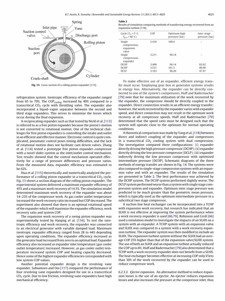
Cycle (Tev = 5 ◦C,Tgc,o = 40 ◦C)
COP Optimum highpressure (bar)
Inter-stagepressure (bar)
Singlecompression,expansionvalve
2.418 100.4 –
Singlecompression,expander
3.211 96.14 –
DCOP 3.496 96.14 82.62
Fig. 13. Cross-section of a rolling piston expander [115].
efrigeration system. Isentropic efficiency of the expander rangedrom 65 to 70%. The COPcooling increased by 40% compared to aranscritical CO2 cycle with throttling valve. The expander alsoncorporated a liquid–vapor separator between the second andhird stage expanders. This serves to minimize the losses whichccur during the final expansion.
A reciprocating expander such as that tested by Nickl et al. [113]s referred to as a free piston expander because the piston’s motions not converted to rotational motion. One of the technical chal-enges for free piston expanders is controlling the intake and outletn an efficient and effective manner. Electronic control is quite com-licated, pneumatic control poses timing difficulties, and the lackf rotational motion does not facilitate cam driven valves. Zhangt al. [114] tested a prototype free piston expander–compressorith a novel slider-system as the inlet/outlet control mechanism.
est results showed that the control mechanism operated effec-ively for a range of pressure differences and pressure ratios.rom the measured data, expander efficiency was estimated toe 62%.
Hua et al. [115] theoretically and numerically analyzed the per-ormance of a rolling piston expander in a transcritical CO2 cycle.ig. 13 shows a section diagram of the rolling piston expander. Thexperimental system delivered a maximum expander efficiency of5% and a maximum work recovery of 14.5%. The simulation modeletermined maximum work recovery of the expander was about4–23% of the compressor work. As gas cooler outlet temperature
ncreased the work recovery ratio increased but COP decreased. Thexperiment also showed that there is an optimal rotational speedf the expander which will maximize the expander efficiency, workecovery ratio and system COP.
The expansion work recovery of a swing piston expander wasxperimentally tested by Haiqing et al. [116]. To test the isen-ropic efficiency and work recovery, the expander was connectedo an electrical generator with variable damped load. Maximumsentropic expander efficiency ranged from 28 to 44% dependingpon operating conditions. The expander efficiency increased ashe generator load increased from zero to an optimal load. Expanderfficiency also increased as expander inlet temperature (gas coolerutlet temperature) increased. However, as gas cooler outlet tem-erature increased system COP and heating capacity decreased.ence some of the highest expander efficiencies corresponded with
ow system COP values.Another potential expander design is the revolving vane
xpander. Subiantoro and Ooi [117] compared the performance ofour revolving vane expanders designed for use in a transcriticalO2 cycle. Due to low friction, revolving vane expanders have highechanical efficiency.
DCHP 3.521 101.3 80.90DCLP 3.163 96.20 47.97
To make effective use of an expander, efficient energy trans-fer must occur. Employing gear box or generator systems resultsin energy loss. Alternatively, the expander can be directly con-nected to one of the system’s compressors. Huff and Radermacher[79] note that for maximum utilization of the work recovered bythe expander, the compressor should be directly coupled to theexpander. Direct connection results in an efficient energy transfer;however, the work recovered by the expander varies with expanderspeed, and direct connection may not result in the optimum workrecovery at all compressor speeds. Huff and Radermacher [79]determined that the speed ratio must be designed such that thesystem will operate close to the optimum for normal operatingconditions.
A theoretical comparison was made by Yang et al. [118] betweendirect and indirect coupling of the expander and compressorsin a transcritical CO2 cooling system with dual compression.The investigation compared three configurations: (i) expanderdirectly driving the high pressure compressor (DCHP); (ii) expanderdirectly driving the low pressure compressor (DCLP); (iii) expanderindirectly driving the low pressure compressor with optimizedintermediate pressure (DCOP). Schematic diagrams of the threemethods of energy transfer are shown in Fig. 14. The systems werealso compared to single-stage compression systems with an expan-sion valve and with an expander. The results of the simulationare presented in Table 2. The best performance was achieved bythe DCHP system. The DCOP system performed slightly worse. TheDCLP system performed worse than a system with single stage com-pression system and expander. Optimum inter stage pressure waspredicted to be much greater than the geometric mean pressure,which is typically used as the optimum intermediate pressure in asubcritical two stage compressor.
A suction line heat exchanger can be incorporated into a TCHPwith expansion work recovery, but research has indicated that anSLHX is not effective at improving the system performance whena work recovery expander is used [66,79]. Robinson and Groll [66]used a simulation model to investigate the impacts of an SLHX on asystem with an expander. A TCHP system with an expansion valveand SLHX was compared to a system with a work recovery expan-sion turbine. The expander system was then modified to include anSLHX. The expansion turbine system without the SLHX had an aver-age COP 25% higher than that of the expansion valve/SLHX system.The use of both an SLHX and an expansion turbine actually reducedthe COP up to 8%. Huff and Radermacher [79] also determined that aTCHP with a work recovery expander does not benefit from a SLHX.The heat exchanger becomes effective at increasing COP only if lessthan 30% of the work recovered by the expander can be used toreduce compressor work.
6.2.3.3. Ejector expansion. An alternative method to reduce expan-sion losses is the use of an ejector. An ejector reduces expansionlosses and also increases the pressure at the compressor inlet, thus

4026 B.T. Austin, K. Sumathy / Renewable and Sustainable Energy Reviews 15 (2011) 4013–4029
Gas Cooler 2
Evaporator
Exp. Turbine Gas
Cooler 1
H.P. Comp.
L.P. Comp.
Gas Cooler
Evaporator
H.P. Comp.
L.P. Comp.
Exp. Turbine
Gas a b cCooler 2
Evaporator
H.P. Comp.
L.P. Comp.
Exp. Turbine
Gas Cooler 1
Gear box
F : (a) ip
raptiCbClp
hctLaqemi
Ttoctcvecvw
ig. 14. Three methods of transferring work recovered from an expansion turbineressure drive; (c) direct low pressure drive [118].
educing compressor work. Fig. 15 shows the schematic diagramnd corresponding P–h diagram of a typical ejector cycle. The basicrinciples of ejector cycle are as follows. High pressure CO2 fromhe gas cooler enters the nozzle of the ejector where its velocity isncreased and pressure is decreased. This decreased pressure drawsO2 vapor from the evaporator into the ejectors mixing cham-er where the pressure increases. A diffuser is utilized to increaseO2 pressure while also lowering the velocity. CO2 then enters a
iquid–vapor separator from which vapor is drawn into the com-ressor and liquid re-enters the evaporator.
An ejector expansion device was first investigated by Korn-auser [119] as an alternative throttling valve for a vaporompression cycle using R12 as a refrigerant. Use of an ejector in aranscritical CO2 cooling cycle was later theoretically analyzed byi and Groll [120] and Deng et al. [121]. Li and Groll [120] modeledmodified ejector cycle which was designed to adjust the vapor
uality at the evaporator inlet and aid steady state operation. Dengt al. [121] focused on the importance of entrainment ratio for opti-ized performance. Both studies found significant improvements
n COPcooling.Sarkar [122] theoretically analyzed the use of an ejector in a
CHP for simultaneous heating and cooling. The study modeledwo systems: a typical ejector cycle and the modified ejector cyclef Li and Groll [120]. The performance difference between the twoycles was negligible except at low evaporator temperatures wherehe modified cycle was slightly less efficient. The ejector-expansionycles were also compared to a conventional system with throttlingalve and a system with a work recovery turbine. The ejector-
xpansion cycles both lowered the optimum discharge pressureompared to the throttling valve cycle. Both ejector cycles had COPalues superior to the conventional cycle, but the system with theork recovery turbine had the best COP.Fig. 15. TCHP with ejector expander: (a) system
ndirect low pressure drive with optimized intermediate pressure; (b) direct high
A prototype transcritical ejector system for cooling was built andtested by Elbel and Hrnjak [123]. Results were compared to a con-ventional system with expansion valve, and the results were usedto validate a numerical model. The ejector improved COPcooling byup to 7%, and ejector efficiency ranged from 3.5 to 14.5%. Cycle per-formance was maximized at an optimum gas cooler pressure, butthe greatest ejector efficiency occurred at a pressure much lowerthan this optimum gas cooler pressure.
A suction line heat exchanger decreases the inlet temperatureof the ejector which increases both ejector efficiency and systemefficiency. The impacts of an SLHX on a transcritical CO2 systemwith an ejector were experimentally tested by Nakagawa et al.[124]. When testing the system without the SLHX, the vapor qual-ity at the exit of the separator was approximately 0.9 for most ofthe test conditions. Thus the ejector system was allowing signifi-cant amounts of liquid to enter the compressor, and COPcooling wasactually lower than an analogous system tested with an expansionvalve. With a gas cooler outlet temp of 42 ◦C, the 60 cm suctionline heat exchanger improved the ejector system’s COPcooling by55–63%. At higher gas cooler outlet temperatures, the performanceimprovement was even more significant.
7. Future potential of transcritical CO2 heat pump systems
CO2 has proven its potential as an appropriate working fluidfor transcritical heat pump systems in the research setting. As dis-cussed in the previous sections, the performance of CO2 systemscan match or exceed the performance of conventional refrigerants
in many applications. In addition, there has already been some com-mercialization of transcritical CO2 heat pump systems, the mostnotable of which are the Japanese heat pump water heaters whichuses CO2 in a transcritical cycle. The systems are manufactured byschematic and (b) cycle P–h diagram [122].

staina
sWb
htu
iita
lteebtg
c[pscispc
itthci
tufssdthttt
emof
8
rdIrqps
B.T. Austin, K. Sumathy / Renewable and Su
everal companies and are marketed as the Eco Cute Heat Pumpater Heater. As of October 2009 more than 2 million units had
een sold in Japan [15].The Eco Cute system has shown that CO2 heat pump systems
ave the potential for commercialization. It is likely that manufac-urers will follow the success of the Eco Cute and will expand these of CO2 beyond residential water heaters.
One application which, to the authors’ knowledge, has not beennvestigated in the academic or commercial setting is the use of CO2n direct expansion geothermal heat pumps. CO2 holds the potentialo provide both environmental and performance benefits in thispplication.
The majority of geothermal heat pump systems today use a dualoop system where a single phase brine solution circulates throughhe buried ground coils and a heat exchanger delivers the absorbednergy to the heat pump loop [125,126]. Less common are the directxpansion geothermal heat pumps (DXGHP) in which no secondaryrine loop exists, but rather the refrigerant passes directly throughhe ground coils. Hence, evaporation takes place directly in theround coils.
One reason a DXGHP is less common is the risk of ground waterontamination by the refrigerant if a leak develops in the system127]. Because it is a non-toxic natural substance, CO2 does notose any risk of ground water contamination. In addition, DXGHPystems require as much as 10 times more refrigerant, by volume,ompared to brine based dual loop system [128]. This can signif-cantly impact the cost of a DXGHP system using an expensiveynthetic refrigerant. Because CO2 is readily available and inex-ensive, the increased charge volume would have less affect onost.
Another issue with DXGHP systems is excessive pressure dropn the evaporator [125]. The long ground coils cause a large fric-ional pressure drop. As the evaporator’s outlet pressure decreaseshe outlet temperature also decreases, thus reducing the system’seating capacity and COP. As will be explained below, a CO2 systeman tolerate a larger pressure drop without the significant decreasen evaporator temperature [82].
In the temperature range applicable for geothermal heat pumps,he change in temperature associated with a given change in sat-ration pressure (i.e. �T/�Psaturation) is much smaller for CO2 thanor other refrigerants. For example, at 0 ◦C a 1 kPa decrease in pres-ure reduces the saturation temperature of CO2 by 0.01 ◦C while theame pressure drop causes the saturation temperature of R134a toecrease by 0.10 ◦C [6]. Thus assuming equal pressure drop throughhe ground coils of a DXGHP and equal inlet temperatures, CO2 willave a greater outlet temperature than other refrigerants [82]. Forhis reason, CO2 may be more suitable than other refrigerants forhe large evaporative pressure drop associated with DXGHP sys-ems.
Carbon dioxide has the potential to improve the performance,nvironmental impacts and economics of direct expansion geother-al heat pump systems. In order to gain a better understanding
f the operating characteristics and feasibility of CO2 in a DXGHP,urther theoretical and experimental research is needed.
. Conclusion
Carbon dioxide was used as a refrigerant in some of the earliestefrigeration systems. CO2 fell out of favor when other refrigerantselivered superior performance over a wider range of conditions.
n light of growing concerns over climate change, CO2 has been
evived as a potential refrigerant due to its benign environmentalualities. To overcome limitations imposed by CO2’s low criticaloint, most of the research has focused on the use of CO2 in a tran-critical cycle. Due to the high working pressures and the distinctble Energy Reviews 15 (2011) 4013–4029 4027
nature of the transcritical cycle, optimization of system compo-nents and process parameters is ongoing.
Research has shown that transcritical CO2 heat pumps can per-form well for water and air heating applications. Furthermore, asignificant body of research has shown that performance of thebasic transcritical cycle can be improved by modifications such asdual-stage compression, multi-stage expansion, expansion workrecover and heat exchanger optimization. As environmental regu-lations further restrict the use of harmful refrigerants, it is possiblethat transcritical CO2 heat pumps will become much more com-mon.
References
[1] U.S. Environmental Protection Agency. High GWP gases and climatechange. U.S. Environmental Protection Agency, www.epa.gov/highgwp/scientific.html; 2010 [accessed 25.07.10].
[2] Intergovernmental Panel on Climate Change. Climate Change 2001: WorkingGroup I: The Scientific Basis. Intergovernmental Panel on Climate Change;2001, 6.12.2.
[3] Emissions from air conditioning systems in motor vehicles.http://europa.eu/legislation summaries/internal market/single market forgoods/motor vehicles/interactions industry policies/l24280 en.htm;September 25, 2007 [accessed 05.10.10].
[4] Directive 2006/40/EC of the European Parliament and of the Council of 17 May2006 relating to emissions from air-conditioning systems in motor vehiclesand amending Council Directive 70/156/EEC. Journal of the European UnionJune 2006;161:12–8.
[5] Neksa P. CO2 heat pump systems. International Journal of Refrigeration2002;25:421–7.
[6] Kim MH, Pettersen J, Bullard CW. Fundamental process and system designissues in CO2 vapor compression systems. Progress in Energy and CombustionScience 2004;30.
[7] Cavallini A, Cecchinato L, Corradi M, Fornasieri E, Zilio C. Two-stage tran-scritical carbon dioxide cycle optimization: a theoretical and experimentalanalysis. International Journal of Refrigeration 2005;28:1274–83.
[8] U.S. Secretary of Commerce. Thermophysical properties of fluid systems,http://webbook.nist.gov/chemistry/fluid; 2008 [accessed 14.05.10].
[9] Pearson A. Carbon dioxide—new uses for an old refrigerant. InternationalJournal of Refrigeration 2005;28:1140–8.
[10] Calm JM. The next generation of refrigerants—historical review, considera-tions, and outlook. International Journal of Refrigeration 2008;31:1123–33.
[11] Lorentzen, G. Trans-critical vapour compression cycle device. PatentWO/07683; 1990.
[12] Lorentzen G, Pettersen J. A new, efficient and environmentally benign systemfor car air-conditioning. International Journal of Refrigeration 1993;16:4–12.
[13] Pettersen J. An efficient new automobile air conditioning system based oncarbon dioxide vapor compression. ASHRAE Transactions 1994;100:657–65.
[14] EcoCute tops one million units. IEA Heat Pump Centre Newsletter 2007:13.[15] EcoCute shipments exceed 2 million landmark. R744.com,
http://www.r744.com/articles/2009-11-26-eco-cute-shipments-exceed-2-million-landmark.php; November 26, 2009 [accessed 04.08.10].
[16] BeyondHFCs. BeyondHFCs position paper on CO2 vending machines.BeyondHFCs, http://www.beyondhfcs.org/search.result.php?Keyword=BeyondHFCs+position+paper+on+CO2+vending+machines; March 20, 2010[accessed 24.10.10].
[17] Hepbasli A, Kalinci Y. A review of heat pump water heating systems. Renew-able and Sustainable Energy Reviews 2009;13:1211–29.
[18] American Society of Mechanical Engineers. The Equitable BuildingHeat Pump System Dedication Ceremony Program. American Soci-ety of Mechanical Engineers, http://files.asme.org/ASMEORG/Communities/History/Landmarks/5541.pdf; May 8, 1980 [accessed 04.08.10].
[19] Hua T, Zhao Y, MinXia L, YiTai MA. Research and application of CO2 refriger-ation and heat pump cycle. Science in China Series E: Technological Sciences2009;52(June (6)):1563–75.
[20] Staub J, Rasmusen BD, Robinson M. CO2 as refrigerant: the transcritical cycle.ACHR News 2004;January 26.
[21] Asinari P, Cecchinato L, Fornasieri E. Effects of thermal conduction inmicrochannel gas coolers for carbon dioxide. International Journal of Refrig-eration 2004;27:577–86.
[22] Oritz TM, Li D, Groll EA. Evaluation of the performance potential of CO2 as arefrigerant in air-to-air air conditioners and heat pumps: system modelingand analysis. Final Report. ARTI; 2003.
[23] Yang J, Ma Y, Liu S, Zeng X. Comparison investigation on the heat transfercharacteristics for supercritical CO2 fluid and conventional refrigerants. In:7th IIR Gustav Lorentzen conference on natural working fluids. 2006.
[24] Krasnoshchekov EA, Kuraeva IV, Protopopov VS. Local heat transfer of carbon
dioxide at supercritical pressure under cooling conditions (translated fromTeplofizika Vysokikh Temperatur) 1970;7: 856–62.[25] Baskov VL, Kuraeva IV, Protopopov VS. Heat transfer with turbulent flow of aliquid at supercritical pressures in tubes under cooling conditions (translatedfrom Teplofizika Vysokikh Temperatur) 1977;15: 81–6.

4 staina
028 B.T. Austin, K. Sumathy / Renewable and Su[26] Petrov NE, Popov VN. Heat transfer and resistance of carbon dioxidebeing cooled in the supercritical region. Thermal Engineering 1985;32:131–4.
[27] Petukhov BS, Popov VN. Theoretical calculation of heat exchange and fric-tional resistance in turbulent flow in tubes of an incompressible fluid withthermophysical properties. High Temperature 1963;I:69–83.
[28] Yoon SH, Kim JH, Hwang YW, Kim MS, Min K, Kim Y. Heat transfer andpressure drop characteristics during the in-tube cooling process of carbondioxide in the supercritical region. International Journal of Refrigeration2003;26:857–64.
[29] Dang C, Hihara E. In-tube cooling heat transfer of supercritical carbon diox-ide, part 1. Experimental measurement. International Journal of Refrigeration2004;27:736–47.
[30] Pettersen J, Rieberer R, Leister A. Heat transfer and pressure drop character-istics of supercritical carbon dioxide in microchannel tubes under cooling.In: Preliminary proceedings of the 4th IIR-Gustav Lorentzen conference onnatural working fluids. 2000. p. 99–106.
[31] Kuang G, Ohadi MM, Zhao Y. Experimental study on gas cooling heat transferfor supercritical CO2 in microchannels. In: Second international conferenceon microchannels and minichannels. 2004. p. 325–32.
[32] Huai XL, Koyama S, Zhao TS. An experimental study of flow and heat transferof supercritical carbon dioxide in multi-port mini channels under coolingconditions. Chemical Engineering Science 2005;60:3337–45.
[33] Huai XL, Koyama S. Heat transfer characteristics of supercritical CO2 flow insmall-channeled structure. Experimental Heat Transfer 2007;20:19–33.
[34] Liao SM, Zhao TS. Measurement of heat transfer coefficients from supercrit-ical carbon dioxide flowing in horizontal mini/micro channels. Journal HeatTransfer 2002;124:413–20.
[35] Pitla SS, Groll EA, Ramadhyani S. New correlation to predict the heat transfercoefficient during in-tube cooling of turbulent supercritical CO2. InternationalJournal of Refrigeration 2002;25:887–95.
[36] Olson DA. Heat transfer of supercritical carbon dioxide flowing in a cooledhorizontal tube. In: Proceedings of 4th IIR-Gustav Lorentzen conference onnatural working fluids. 2000. p. 251–8.
[37] Kuang G, Ohadi M. Semi-empirical correlation of gas cooling heat trans-fer of supercritical carbon dioxide in microchannels. HVAC&R Research2008;14:861–70.
[38] Kim JH, Yoon MS, Kim Y. An experimental investigation of heat transfercharacteristics during in-tube gas cooling process of carbon dioxide. (IIF-IIRCommission B1) B6 2001: 17–21.
[39] Oh HK, Son CH. New correlation to predict the heat transfer coefficient in-tubecooling of supercritical CO2 in horizontal macro-tubes. Experimental Thermaland Fluid Science 2010;34:1230–41.
[40] Petrov NE, Popov VN. Heat transfer and resistance of carbon dioxide beingcooled in the supercritical region. Thermal Engineering 1985;32:131–4.
[41] Pettersen J, Rieberer R, Munkejord ST. Heat transfer and pressure drop forflow of supercritical and subcritical CO2 in microchannel tubes. Final Tech-nical Report. European Research Office of the U.S. Army, United States Army,London, England; 2000.
[42] Son CH, Park SJ. An experimental study on heat transfer and pressure dropcharacteristics of carbon dioxide during gas cooling process in a horizontaltube. International Journal of Refrigeration 2006;29:539–46.
[43] Cheng L, Ribatski G, Thome JR. Analysis of supercritical CO2 cooling in macro-and micro-channels. International Journal of Refrigeration 2008;31:1301–16.
[44] Yoon SH, Cho ES, Hwang YW, Kim MS, Min K, Kim Y. Characteristics of evap-orative heat transfer and pressure drop of carbon dioxide and correlationdevelopment. International Journal of refrigeration 2004;27:111–9.
[45] Bredesen AM, Hafner AH, Pettersen J, Neksa P, Aflekt K. Heat transfer and pres-sure drop for in-tube evaporation of CO2. College Park: IIF-IIR-Commission B1,with E1 & E2; 1997.
[46] Cho JM, Kim MS. Experimental studies on the evaporative heat transfer andpressure drop of CO2 in smooth and micro-fin tubes of the diameters of 5.00and 9.52 mm. International Journal of Refrigeration 2007;30:986–94.
[47] Yun R, Kim Y, Kim MS, Choi Y. Boiling heat transfer and dryout phenomenonof CO2 in horizontal smooth tube. International Journal of Heat and MassTransfer 2003;46:2353–61.
[48] Zhao X, Bansal PK. Flow boiling heat transfer characteristics of CO2 at lowtemperatures. International Journal of Refrigeration 2007;30:937–45.
[49] Oh HK, Ku HG, Roh GS, Park SJ, Son CH. Flow boiling heat transfer charac-teristics of carbon dioxide in a horizontal tube. Applied Thermal Engineering2008;28:1022–30.
[50] Park CY, Hrnjak PS. CO2 and R410A flow boiling heat transfer, pressure drop,and flow pattern at low temperatures in a horizontal smooth tube. Interna-tional Journal of Refrigeration 2007;30:166–78.
[51] Wu XM, Zhao HY, Wang WC, Jing L, Zhang L. Experimental study on evaporat-ing heat transfer of CO2 in thin tube. Journal of Engineering Thermophysics2005;26:823–5.
[52] Schael AE, Kind M. Flow pattern and heat transfer characteristics during flowboiling of CO2 in a horizontal micro-fin tube and comparison with smoothtube data. International Journal of Refrigeration 2005;28:1186–95.
[53] Mastrullo R, Mauro AW, Rosato A, Vanoli GP. Carbon dioxide heat transfer
coefficients and pressure drops during flow boiling: assessment of predictivemethods. International Journal of Refrigeration 2010;33:1068–85.[54] Cheng L, Ribatski G, Moreno Quiben Q, Thome JR. New prediction methodsfor CO2 evaporation inside tubes: part I—a two-phase flow pattern map and aflow pattern based phenomenological model for two-phase flow frictional
ble Energy Reviews 15 (2011) 4013–4029
pressure drops. International Journal of Heat and Mass Transfer 2008;51:111–24.
[55] Jung DS, Radermacher R, McLinden M, Didon D. A study of flow boiling heattransfer with refrigerant mixtures. International Journal of Heat and MassTransfer 1989;32:1751–64.
[56] Muller-Steinhagen H, Heck K. A simple friction pressure correlationfor two-phase flow in pipes. Chemical Engineering Process 1986;20:297–308.
[57] Friedel L. Improved friction drop correlation for horizontal and vertical two-phase pipe flow. In: European two-phase flow group meeting. 1979. PaperE2.
[58] Kauf F. Determination of the optimum high pressure for transcriti-cal CO2-refrigeration cycles. International Journal of Thermal Sciences1999;38:325–30.
[59] Liao SM, Zhao TS, Jakobsen A. A correlation of optimal heat rejection pres-sures in transcritical carbon dioxide cycles. Applied Thermal Engineering2000;20:831–41.
[60] Sarkar J, Bhattacharyya S, Gopal MR. Optimization of a transcritical CO2 heatpump cycle for simultaneous cooling and heating applications. InternationalJournal of Refrigeration 2004;27:830–8.
[61] Zhang XP, Fan XW, Wang FK, Shen HG. Theoretical and experimental studieson optimum heat rejection pressure for a CO2 heat pump system. AppliedThermal Engineering 2010.
[62] Laipradit P, Tiansuwan J, Kiatsiriroat T, Aye L. Theoretical performanceanalysis of heat pump water heaters using carbon dioxide as refrigerant.International Journal of Energy Research 2007;32(4):356–66.
[63] Cecchinato L, Corradi M, Fornasieri E, Zamboni L. Carbon dioxide as refrig-erant for tap water heat pumps: a comparison with the traditional solution.International Journal of Refrigeration 2005;28:1250–8.
[64] Fernandez N, Hwang Y, Radermacher R. Comparison of CO2 heat pump waterheater performance with baseline cycle and two high COP cycles. Interna-tional Journal of Refrigeration 2010;33:635–44.
[65] Stene J. Residential CO2 heat pump system for combined space heating andhot water heating. International Journal of Refrigeration 2005;28:1259–65.
[66] Robinson DM, Groll EA. Efficiencies of transcritical CO2 cycles withand without an expansion turbine. International Journal of Refrigeration1998;21(7):577–89.
[67] Kim SG, Kim YJ, Lee G, Kim MS. The performance of a transcritical CO2 cyclewith an internal heat exchanger for hot water heating. International Journalof Refrigeration 2005;28:1064–72.
[68] Chen Y, Gu J. The optimum high pressure for CO2 transcritical refrigerationsystems with internal heat exchangers. International Journal of Refrigeration2005;28:1238–49.
[69] White SD, Yarrall MG, Cleland DJ, Hedley RA. Modeling the performance ofa transcritical CO2 heat pump for high temperature heating. InternationalJournal of Refrigeration 2002;25:479–86.
[70] Sarkar J, Bhattacharyya S, Gopal MR. Simulation of a transcritical CO2 heatpump cycle for simultaneous cooling and heating applications. InternationalJournal of Refrigeration 2006;29:735–43.
[71] Byrne P, Miriel J, Lenat Y. Design and simulation of a heat pump for simulta-neous heating and cooling using HFC or CO2 as a working fluid. InternationalJournal of Refrigeration 2009;32:1711–23.
[72] Sarkar J, Bhattacharyya S, Gopal MR. Natural refrigerant-based subcriticaland transcritical cycles for high temperature heating. International Journalof Refrigeration 2007;30:3–10.
[73] Neksa P, Rekstad H, Zakeri GR, Schiefloe PA. CO2 heat pump water heater:characteristics, system design and experimental results. International Journalof Refrigeration 1998;21:172–9.
[74] Anstett P. Measurement of the performance of an air/water heat pump usingCO2 or R744 for the production of hot water for use in a hospital. IEA HeatPump Centre Newsletter 2006:35–8.
[75] Hihara E. Performance test of a carbon dioxide heat pump for combineddomestic hot water and floor heating. IEA Heat Pump Centre Newsletter2006:21–3.
[76] Cho H, Ryu C, Kim Y, Kim HY. Effects of refrigerant charge amount on theperformance of a transcritical CO2 heat pump. International Journal of Refrig-eration 2005;28:1266–73.
[77] Tamura T, Yakumaru Y, Nishiwaki F. Experimental study on automotivecooling and heating air conditioning system using CO2 as a refrigerant. Inter-national Journal of Refrigeration 2005;28:1302–7.
[78] Richter MR, Song SM, Yin JM, Kim MH, Bullard CW, Hrnjak PS. Experimen-tal results of transcritical CO2 heat pump for residential application. Energy2003;28:1005–19.
[79] Huff HJ, Radermacher R. CO2 compressor–expander analysis. Arlington, VA:Air-Conditioning and Refrigeration Technology Institute; 2003.
[80] Yang JL, Ma YT, Li MX, Guan HQ. Exergy analysis of transcritical carbon dioxiderefrigeration cycle with an expander. Energy 2005;30:1162–75.
[81] Sarkar J, Bhattacharyya S, Gopal MR. Transcritical CO2 heat pump systems:exergy analysis including heat transfer and fluid flow effects. Energy Conver-sion and Management 2005;46:2053–67.
[82] Pettersen J, Hafner A, Skaugen G. Development of compact heat exchang-
ers for CO2 air-conditioning systems. International Journal of Refrigeration1998;21:180–93.[83] Fronk BM, Garimella S. Water-coupled carbon dioxide microchannel gascooler for heat pump water heaters: part II—model development and vali-dation. International Journal of Refrigeration 2011;34:17–28.
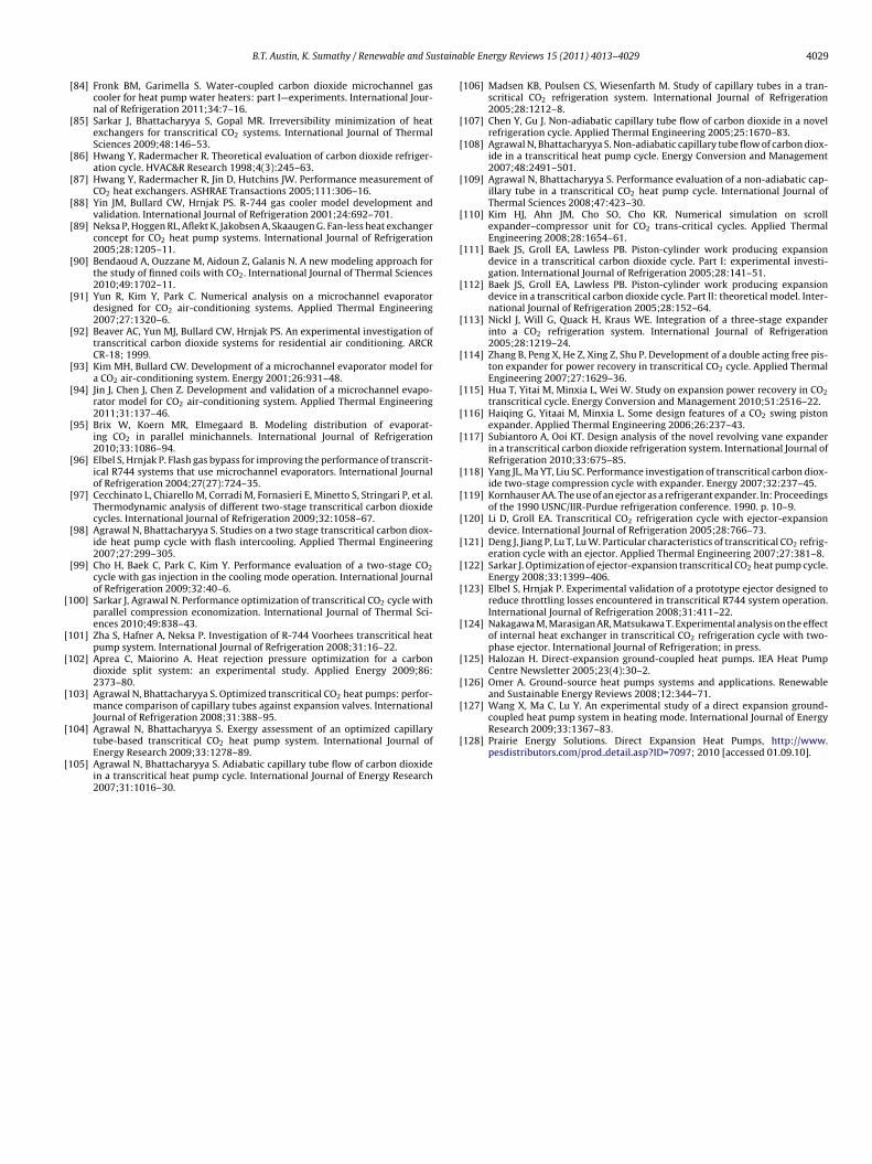
staina
[
[
[
[
[
[
[127] Wang X, Ma C, Lu Y. An experimental study of a direct expansion ground-coupled heat pump system in heating mode. International Journal of EnergyResearch 2009;33:1367–83.
B.T. Austin, K. Sumathy / Renewable and Su
[84] Fronk BM, Garimella S. Water-coupled carbon dioxide microchannel gascooler for heat pump water heaters: part I—experiments. International Jour-nal of Refrigeration 2011;34:7–16.
[85] Sarkar J, Bhattacharyya S, Gopal MR. Irreversibility minimization of heatexchangers for transcritical CO2 systems. International Journal of ThermalSciences 2009;48:146–53.
[86] Hwang Y, Radermacher R. Theoretical evaluation of carbon dioxide refriger-ation cycle. HVAC&R Research 1998;4(3):245–63.
[87] Hwang Y, Radermacher R, Jin D, Hutchins JW. Performance measurement ofCO2 heat exchangers. ASHRAE Transactions 2005;111:306–16.
[88] Yin JM, Bullard CW, Hrnjak PS. R-744 gas cooler model development andvalidation. International Journal of Refrigeration 2001;24:692–701.
[89] Neksa P, Hoggen RL, Aflekt K, Jakobsen A, Skaaugen G. Fan-less heat exchangerconcept for CO2 heat pump systems. International Journal of Refrigeration2005;28:1205–11.
[90] Bendaoud A, Ouzzane M, Aidoun Z, Galanis N. A new modeling approach forthe study of finned coils with CO2. International Journal of Thermal Sciences2010;49:1702–11.
[91] Yun R, Kim Y, Park C. Numerical analysis on a microchannel evaporatordesigned for CO2 air-conditioning systems. Applied Thermal Engineering2007;27:1320–6.
[92] Beaver AC, Yun MJ, Bullard CW, Hrnjak PS. An experimental investigation oftranscritical carbon dioxide systems for residential air conditioning. ARCRCR-18; 1999.
[93] Kim MH, Bullard CW. Development of a microchannel evaporator model fora CO2 air-conditioning system. Energy 2001;26:931–48.
[94] Jin J, Chen J, Chen Z. Development and validation of a microchannel evapo-rator model for CO2 air-conditioning system. Applied Thermal Engineering2011;31:137–46.
[95] Brix W, Koern MR, Elmegaard B. Modeling distribution of evaporat-ing CO2 in parallel minichannels. International Journal of Refrigeration2010;33:1086–94.
[96] Elbel S, Hrnjak P. Flash gas bypass for improving the performance of transcrit-ical R744 systems that use microchannel evaporators. International Journalof Refrigeration 2004;27(27):724–35.
[97] Cecchinato L, Chiarello M, Corradi M, Fornasieri E, Minetto S, Stringari P, et al.Thermodynamic analysis of different two-stage transcritical carbon dioxidecycles. International Journal of Refrigeration 2009;32:1058–67.
[98] Agrawal N, Bhattacharyya S. Studies on a two stage transcritical carbon diox-ide heat pump cycle with flash intercooling. Applied Thermal Engineering2007;27:299–305.
[99] Cho H, Baek C, Park C, Kim Y. Performance evaluation of a two-stage CO2
cycle with gas injection in the cooling mode operation. International Journalof Refrigeration 2009;32:40–6.
100] Sarkar J, Agrawal N. Performance optimization of transcritical CO2 cycle withparallel compression economization. International Journal of Thermal Sci-ences 2010;49:838–43.
101] Zha S, Hafner A, Neksa P. Investigation of R-744 Voorhees transcritical heatpump system. International Journal of Refrigeration 2008;31:16–22.
102] Aprea C, Maiorino A. Heat rejection pressure optimization for a carbondioxide split system: an experimental study. Applied Energy 2009;86:2373–80.
103] Agrawal N, Bhattacharyya S. Optimized transcritical CO2 heat pumps: perfor-mance comparison of capillary tubes against expansion valves. InternationalJournal of Refrigeration 2008;31:388–95.
104] Agrawal N, Bhattacharyya S. Exergy assessment of an optimized capillary
tube-based transcritical CO2 heat pump system. International Journal ofEnergy Research 2009;33:1278–89.105] Agrawal N, Bhattacharyya S. Adiabatic capillary tube flow of carbon dioxidein a transcritical heat pump cycle. International Journal of Energy Research2007;31:1016–30.
ble Energy Reviews 15 (2011) 4013–4029 4029
[106] Madsen KB, Poulsen CS, Wiesenfarth M. Study of capillary tubes in a tran-scritical CO2 refrigeration system. International Journal of Refrigeration2005;28:1212–8.
[107] Chen Y, Gu J. Non-adiabatic capillary tube flow of carbon dioxide in a novelrefrigeration cycle. Applied Thermal Engineering 2005;25:1670–83.
[108] Agrawal N, Bhattacharyya S. Non-adiabatic capillary tube flow of carbon diox-ide in a transcritical heat pump cycle. Energy Conversion and Management2007;48:2491–501.
[109] Agrawal N, Bhattacharyya S. Performance evaluation of a non-adiabatic cap-illary tube in a transcritical CO2 heat pump cycle. International Journal ofThermal Sciences 2008;47:423–30.
[110] Kim HJ, Ahn JM, Cho SO, Cho KR. Numerical simulation on scrollexpander–compressor unit for CO2 trans-critical cycles. Applied ThermalEngineering 2008;28:1654–61.
[111] Baek JS, Groll EA, Lawless PB. Piston-cylinder work producing expansiondevice in a transcritical carbon dioxide cycle. Part I: experimental investi-gation. International Journal of Refrigeration 2005;28:141–51.
[112] Baek JS, Groll EA, Lawless PB. Piston-cylinder work producing expansiondevice in a transcritical carbon dioxide cycle. Part II: theoretical model. Inter-national Journal of Refrigeration 2005;28:152–64.
[113] Nickl J, Will G, Quack H, Kraus WE. Integration of a three-stage expanderinto a CO2 refrigeration system. International Journal of Refrigeration2005;28:1219–24.
[114] Zhang B, Peng X, He Z, Xing Z, Shu P. Development of a double acting free pis-ton expander for power recovery in transcritical CO2 cycle. Applied ThermalEngineering 2007;27:1629–36.
[115] Hua T, Yitai M, Minxia L, Wei W. Study on expansion power recovery in CO2
transcritical cycle. Energy Conversion and Management 2010;51:2516–22.[116] Haiqing G, Yitaai M, Minxia L. Some design features of a CO2 swing piston
expander. Applied Thermal Engineering 2006;26:237–43.[117] Subiantoro A, Ooi KT. Design analysis of the novel revolving vane expander
in a transcritical carbon dioxide refrigeration system. International Journal ofRefrigeration 2010;33:675–85.
[118] Yang JL, Ma YT, Liu SC. Performance investigation of transcritical carbon diox-ide two-stage compression cycle with expander. Energy 2007;32:237–45.
[119] Kornhauser AA. The use of an ejector as a refrigerant expander. In: Proceedingsof the 1990 USNC/IIR-Purdue refrigeration conference. 1990. p. 10–9.
[120] Li D, Groll EA. Transcritical CO2 refrigeration cycle with ejector-expansiondevice. International Journal of Refrigeration 2005;28:766–73.
[121] Deng J, Jiang P, Lu T, Lu W. Particular characteristics of transcritical CO2 refrig-eration cycle with an ejector. Applied Thermal Engineering 2007;27:381–8.
[122] Sarkar J. Optimization of ejector-expansion transcritical CO2 heat pump cycle.Energy 2008;33:1399–406.
[123] Elbel S, Hrnjak P. Experimental validation of a prototype ejector designed toreduce throttling losses encountered in transcritical R744 system operation.International Journal of Refrigeration 2008;31:411–22.
[124] Nakagawa M, Marasigan AR, Matsukawa T. Experimental analysis on the effectof internal heat exchanger in transcritical CO2 refrigeration cycle with two-phase ejector. International Journal of Refrigeration; in press.
[125] Halozan H. Direct-expansion ground-coupled heat pumps. IEA Heat PumpCentre Newsletter 2005;23(4):30–2.
[126] Omer A. Ground-source heat pumps systems and applications. Renewableand Sustainable Energy Reviews 2008;12:344–71.
[128] Prairie Energy Solutions. Direct Expansion Heat Pumps, http://www.pesdistributors.com/prod detail.asp?ID=7097; 2010 [accessed 01.09.10].