Embed Size (px)
Citation preview
Renewable and Sustainable Energy Reviews 16 (2012) 6823–6850
Contents lists available at SciVerse ScienceDirect
Renewable and Sustainable Energy Reviews
1364-03
http://d
n Corr
E-m
journal homepage: www.elsevier.com/locate/rser
Indirect evaporative cooling: Past, present and future potentials
Zhiyin Duan a, Changhong Zhan b, Xingxing Zhang a, Mahmud Mustafa a, Xudong Zhao a,n,Behrang Alimohammadisagvand c, Ala Hasan c
a Institute of Energy and Sustainable Development, De Montfort University, The Gateway, Leicester, LE1 9BH, UKb School of Architecture, Heilongjiang Cold Climate Architecture Science Key Laboratory, Harbin Institute of Technology, 66 Xidazhi Street 150001, Chinac School of Engineering, Department of Energy Technology, Aalto University, PO Box 14400, FI-00076 Aalto, Finland
a r t i c l e i n f o
Article history:
Received 27 March 2012
Received in revised form
30 June 2012
Accepted 15 July 2012
Keywords:
Indirect evaporative cooling
Heat and mass transfer
Research
Heat and mass exchanger
Effectiveness
Energy efficiency
21/$ - see front matter & 2012 Elsevier Ltd. A
x.doi.org/10.1016/j.rser.2012.07.007
esponding author. Tel.: þ44 1482 466684; fa
ail address: [email protected] (X. Zhao
a b s t r a c t
This paper reported a review based study into the Indirect Evaporative Cooling (IEC) technology, which
was undertaken from a variety of aspects including background, history, current status, concept,
standardisation, system configuration, operational mode, research and industrialisation, market
prospect and barriers, as well as the future focuses on R&D and commercialisation. This review work
indicated that the IEC technology has potential to be an alternative to conventional mechanical vapour
compression refrigeration systems to take up the air conditioning duty for buildings. Owing to the
continuous progress in technology innovation, particularly the M-cycle development and associated
heat and mass transfer and material optimisation, the IEC systems have obtained significantly
enhanced cooling performance over those the decade ago, with the wet-bulb effectiveness of greater
than 90% and energy efficiency ratio (EER) up to 80. Structure of the IEC heat and mass exchanger varied
from flat-plate-stack, tube, heat pipe and potentially wave-form. Materials used for making the
exchanger elements (plate/tube) included fibre sheet with the single side water proofing, aluminium
plate/tube with single side wicked setting (grooved, meshed, toughed etc), and ceramic plate/tube with
single side water proofing. Counter-current water flow relevant to the primary air is considered the
favourite choice; good distribution of the water stream across the wet surface of the exchanger plate
(tube) and adequate (matching up the evaporation) control of the water flow rate are critical to
achieving the expected system performance. It was noticed that the IEC devices were always in
combined operation with other cooling measures and the commonly available IEC related operational
modes are (1) IEC/DEC system; (2) IEC/DEC/mechanical vapour compression system; (3) IEC/desiccant
system; (4) IEC/chilled water system; and (5) IEC/heat pipe system. The future potential operational
modes may also cover the IEC-inclusive fan coil units, air handle units, cooling towers, solar driven
desiccant cycle, and Rankine cycle based power generation system etc. Future works on the IEC
technology may focus on (1) heat exchanger structure and material; (2) water flowing, distribution and
treatment; (3) incorporation of the IEC components into conventional air conditioning products to
enable combined operation between the IEC and other cooling devices; (4) economic, environment and
social impacts; (5) standardisation and legislation; (6) public awareness and other dissemination
measures; and (7) manufacturing and commercialisation. All above addressed efforts may help increase
the market ratio of the IEC to around 20% in the next 20 years, which will lead to significant saving of
fossil fuel consumption and cut of carbon emission related to buildings.
& 2012 Elsevier Ltd. All rights reserved.
Contents
1. Introduction . . . . . . . . . . . . . . . . . . . . . . . . . . . . . . . . . . . . . . . . . . . . . . . . . . . . . . . . . . . . . . . . . . . . . . . . . . . . . . . . . . . . . . . . . . . . . . . . . . . . . 6824
2. History and current status of the indirect evaporative cooling (IEC) technology . . . . . . . . . . . . . . . . . . . . . . . . . . . . . . . . . . . . . . . . . . . . . . . 6826
3. Basic concept and operational principle, performance evaluation methods/standards, system configuration and operational modes related to the
IEC . . . . . . . . . . . . . . . . . . . . . . . . . . . . . . . . . . . . . . . . . . . . . . . . . . . . . . . . . . . . . . . . . . . . . . . . . . . . . . . . . . . . . . . . . . . . . . . . . . . . . . . . . . . . . . . . 6830
3.1. Basic concept of the IEC and its operational principle . . . . . . . . . . . . . . . . . . . . . . . . . . . . . . . . . . . . . . . . . . . . . . . . . . . . . . . . . . . . . . 6830
3.1.1. Conventional IEC systems . . . . . . . . . . . . . . . . . . . . . . . . . . . . . . . . . . . . . . . . . . . . . . . . . . . . . . . . . . . . . . . . . . . . . . . . . . . . . 6830
3.1.2. M-Cycle IEC systems . . . . . . . . . . . . . . . . . . . . . . . . . . . . . . . . . . . . . . . . . . . . . . . . . . . . . . . . . . . . . . . . . . . . . . . . . . . . . . . . 6831
ll rights reserved.
x: þ44 1482 466664.
).
Z. Duan et al. / Renewable and Sustainable Energy Reviews 16 (2012) 6823–68506824
3.2. Performance evaluation standards and indicative parameters . . . . . . . . . . . . . . . . . . . . . . . . . . . . . . . . . . . . . . . . . . . . . . . . . . . . . . . . 6832
3.2.1. Standards overview . . . . . . . . . . . . . . . . . . . . . . . . . . . . . . . . . . . . . . . . . . . . . . . . . . . . . . . . . . . . . . . . . . . . . . . . . . . . . . . . . 6832
3.2.2. Indicative parameters. . . . . . . . . . . . . . . . . . . . . . . . . . . . . . . . . . . . . . . . . . . . . . . . . . . . . . . . . . . . . . . . . . . . . . . . . . . . . . . . 6833
3.2.3. Summary of the IEC parametric performance . . . . . . . . . . . . . . . . . . . . . . . . . . . . . . . . . . . . . . . . . . . . . . . . . . . . . . . . . . . . . 6834
3.3. System configuration and operational mode . . . . . . . . . . . . . . . . . . . . . . . . . . . . . . . . . . . . . . . . . . . . . . . . . . . . . . . . . . . . . . . . . . . . . 6834
3.3.1. System configuration . . . . . . . . . . . . . . . . . . . . . . . . . . . . . . . . . . . . . . . . . . . . . . . . . . . . . . . . . . . . . . . . . . . . . . . . . . . . . . . . 6834
3.3.2. Operational mode. . . . . . . . . . . . . . . . . . . . . . . . . . . . . . . . . . . . . . . . . . . . . . . . . . . . . . . . . . . . . . . . . . . . . . . . . . . . . . . . . . . 6836
4. Researches and achievements related to the IEC . . . . . . . . . . . . . . . . . . . . . . . . . . . . . . . . . . . . . . . . . . . . . . . . . . . . . . . . . . . . . . . . . . . . . . . . 6838
4.1. Material study . . . . . . . . . . . . . . . . . . . . . . . . . . . . . . . . . . . . . . . . . . . . . . . . . . . . . . . . . . . . . . . . . . . . . . . . . . . . . . . . . . . . . . . . . . . . . 6838
4.2. Mathematical theory and computer simulation . . . . . . . . . . . . . . . . . . . . . . . . . . . . . . . . . . . . . . . . . . . . . . . . . . . . . . . . . . . . . . . . . . . 6839
4.3. Experimental work and model validation . . . . . . . . . . . . . . . . . . . . . . . . . . . . . . . . . . . . . . . . . . . . . . . . . . . . . . . . . . . . . . . . . . . . . . . . 6841
4.4. Effect of the water distribution . . . . . . . . . . . . . . . . . . . . . . . . . . . . . . . . . . . . . . . . . . . . . . . . . . . . . . . . . . . . . . . . . . . . . . . . . . . . . . . . 6842
4.5. M-cycle IEC systems and associated performance measures . . . . . . . . . . . . . . . . . . . . . . . . . . . . . . . . . . . . . . . . . . . . . . . . . . . . . . . . . 6845
4.6. Social-technical studies including energy saving, costing, payback, life cycle analyses, as well as environmental impact . . . . . . . . . 6845
5. The current market profile and potential barriers existing for marketing exploitation . . . . . . . . . . . . . . . . . . . . . . . . . . . . . . . . . . . . . . . . . . 6846
5.1. Current market profile . . . . . . . . . . . . . . . . . . . . . . . . . . . . . . . . . . . . . . . . . . . . . . . . . . . . . . . . . . . . . . . . . . . . . . . . . . . . . . . . . . . . . . . 6846
5.2. Potential market barriers . . . . . . . . . . . . . . . . . . . . . . . . . . . . . . . . . . . . . . . . . . . . . . . . . . . . . . . . . . . . . . . . . . . . . . . . . . . . . . . . . . . . . 6847
6. Future research focuses and trend of development relating to the indirect evaporative cooling (IEC) . . . . . . . . . . . . . . . . . . . . . . . . . . . . . . 6847
7. Conclusions . . . . . . . . . . . . . . . . . . . . . . . . . . . . . . . . . . . . . . . . . . . . . . . . . . . . . . . . . . . . . . . . . . . . . . . . . . . . . . . . . . . . . . . . . . . . . . . . . . . . . 6848
Acknowledgement . . . . . . . . . . . . . . . . . . . . . . . . . . . . . . . . . . . . . . . . . . . . . . . . . . . . . . . . . . . . . . . . . . . . . . . . . . . . . . . . . . . . . . . . . . . . . . . . 6848
References . . . . . . . . . . . . . . . . . . . . . . . . . . . . . . . . . . . . . . . . . . . . . . . . . . . . . . . . . . . . . . . . . . . . . . . . . . . . . . . . . . . . . . . . . . . . . . . . . . . . . . 6849
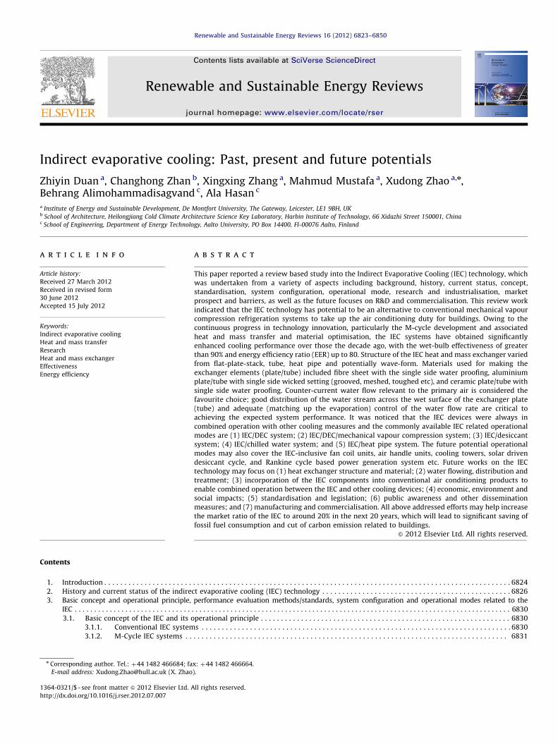
Fig. 1. Conventional vapour compression refrigeration cycle.
1. Introduction
The building sector is responsible for around 30–40% of worldtotal energy consumption and similar proportion of global carbonemission [1]. Heating, Ventilation and Air Conditioning (HVAC) isthe major energy user in a building and consumes around 50% ofthe total supplied energy [1]. Air-conditioning, representing animportant function of the HVAC system, is becoming increasinglycrucial for many buildings, particularly those public types e.g.,office blocks, supermarkets, sport centers, airports, factories etc,owing to recent frequent warm spells, improved building insula-tion and growth of in-house heat generating appliances. In hotand/or arid regions e.g., Middle East, Far East and North American,air conditioning has become part of the people’s life need; whilstits use in mild climatic regions such as UK, Denmark and otherEuropean regions is also rapidly growing [2]. During the hottestsummer period when air conditioning is in full operation, manycities in China, Kuwait etc. [3], experienced difficult power-over-loads that often led to unwanted grid ‘cut-off’. Concerning withthe extensive need for air conditioning and growing pressure onenergy saving and carbon emission in building sector [4], seeking forroutes to reduce fossil fuel consumption and increase utilization ofnatural or renewable energy during air conditioning process is ofparticular importance.
Air conditioning market is currently dominated by the mechan-ical vapour compression refrigeration system which, formed as aloop (Fig. 1) comprising an evaporator, a condenser, a compressorand an expansion valve, allows a refrigerant (e.g., R-22, R-134a,R410A) to circulate around. Within the evaporator, the refrigerantabsorbs heat from the surrounding causing change of its phase fromliquid to vapour and subsequently the cooling of the surroundingmedium (e.g., water, air). Afterwards, the refrigerant is fed into thecompressor which, through delivering a significant electrical power,enables generation of a high pressure, super-saturated refrigerantvapour. This form of vapour then enters into the condenser; whereasit loses heat to surrounding medium, leading to condensation of thehigh pressure refrigerant vapour. Leaving off the condenser, therefrigerant comes across an expansion valve which, through thethrottle effect, causes reduction of the refrigerant’s pressure. Thislow pressure refrigerant is then back to the evaporator to recollect
the heat. This kind of cycle was fully established and has beenin practical use for over 100 years. Owing to its relatively longhistory and massive scale production, the technology presents manyadvantages e.g., good stability in performance, low cost, long lifecycle time and reasonable good energy performance (COP in therange of 2–4). However, this type of system has a major disadvan-tage that lies in high demand to electricity for operation of thecompressor. Owing to the high dependency of fossil fuel burning incurrent electrical industry, this technology is regarded as neithersustainable nor environmentally friendly [5].
Absorption and adsorption cooling, as a potential alternative toconventional mechanical vapour compression systems, removeneed for the power-intensive compressor but add up requirementfor high temperature vapour or water. The absorbent system is aliquid desiccant cycle comprising a desiccant absorber, regenera-tor, condenser, evaporator, expansion vale and piping connec-tions, as shown schematically in Fig. 2. This system would absorbheat on one side (evaporator) to enable cooling of a medium (e.g.,

Nomenclatures
c specific heat at constant pressure, kJ/ (kg k)V volumetric flow rate, m3/sm mass flow rate, kg/sQ cooling capacity of evaporative cooler, kWt air flow temperature, 1Cw moisture content, kg/kg (dry air)i enthalpy, kJ/kgu air velocity, m/sW measured total power consumption, kWECER evaporative cooler efficiency ratio, measured at
tp,db,in¼32.8 1C, tp,wb,in¼20.6 1C, troom¼26.7 1CCOP coefficient of performanceEER energy efficiency ratio, which is the COP multiplied
by 3.413.
Greek symbols
r density, kg/m3
e saturation effectiveness
Subscripts
f airw waterp primary channels secondary channeldb dry bulbwb wet bulbdp dew pointin inletout outlet
Z. Duan et al. / Renewable and Sustainable Energy Reviews 16 (2012) 6823–6850 6825
air or water) and reject the absorbed heat on the other side(condenser) simultaneously; whilst the absorber and generator incombination act as the thermal compressor of the system. Owingto the need of an expensive and metal-corrosive chemical solution,e.g., LiCl, LiBr, CaCl2 or KCOOH, the system configuration appears tobe complex and its cost is therefore high [6]. The adsorbent systemhas a similar system construction to the absorbent system but usesthe desiccant wheel or beds as the replacement of the absorber andregenerator, which accommodate a solid desiccant such as Silica gel,Zeolites, Molecule sieves or Polymer. Both absorption and adsorp-tion systems need heat as a driving force and therefore are onlysuitable for occasions where heat source is available. These systemshave a relatively lower thermal COP in the range 0.4–1.2, which leadto intensive use of heat energy. Further, relatively complex systemconfiguration containing pressurised and de-pressurised componentsin the absorption and adsorption systems reduces their attraction tousers [6].
Table 1A general comparison between the currently available air conditioning systems.
System
type
Mechanical vapour compression Absorption/adsorp
Features Dominate the air conditioning market
Mature technology with stable performance
and low cost
Driven by electricity with COP of 2 to 3
Energy intensive
Driven by heat (w
limited applicatio
Complex system c
Low COP: 0.4–1.2
Energy intensive
Fig. 2. Absorption cooling cycle.
Over the past decades, evaporative cooling, utilizing theprinciple of water evaporation for heat absorbing, has gainedgrowing popularity for use in air conditioning [7–9], owing to itssimplicity in structure and good use of natural energy (i.e., latentheat of water) existing in ambient. This led to enhanced systemCOP in the range 15–20, which is significantly higher than that forconventional vapour compression and adsorption/absorption airconditioning systems. Direct Evaporative Cooling (DEC) keeps theprimary (product) air in direct contact with water, causingevaporation of the water and reduction of temperature of theair simultaneously. As a result, the vaporised water, in form ofvapour, is added into the air, which often creates wetter aircondition and causes discomfort to the residents. To overcomethis difficulty, Indirect Evaporative Cooling (IEC) was brought intoconsideration. In an IEC, water is separated from the primary(product) air using the heat exchanging plate [10,11]. Duringoperation, evaporation of the water occurs in one side of theplate where the secondary (working) air moves along; while theprimary (product) air flows across the other side. Evaporation ofthe water causes reduction of the temperature of the plate,resulting in heat transfer between the primary air and the plate.Meanwhile, the vaporised water is taken away by the secondary(working) air across the wet-side of plate. By doing so, theprimary air is cooled but no moisture is added into it, which isideal for purpose of building air conditioning. Owing to thisadvantage, Indirect Evaporative Cooling (IEC) has potential tobecome a feasible alternative to conventional mechanical vapourcompression systems, which would lead to realisation of low(zero) carbon air conditioning served for buildings.
Biggest problem facing the Indirect Evaporative Cooling (IEC)technology lies in its high level of dependency to ambient aircondition. The driving force of either direct or indirect evapora-tive cooling is the temperature difference between the dry-bulb
tion Evaporative cooling
aste, renewable or gas) with
n
onfiguration and operational status
Using water as the cooling medium
Simple system configuration and
operational status
High dependency to the ambient
condition
High COP: 15 to 20
Energy economic
Z. Duan et al. / Renewable and Sustainable Energy Reviews 16 (2012) 6823–68506826
and wet-bulb (or dew point) of the process air, which, in humid ormild climate regions, is very small and thus leads to very limitedsystem cooling capacity. Further, instability of the ambient aircondition (temperature/humidity) also causes unsteady operationof the Indirect Evaporative Cooling (IEC) system [12]. A generalcomparison among the above mentioned air conditioning systemsis indicated in Table 1.
To understand the performance, current status, advantagesand disadvantages of the Indirect Evaporative Cooling (IEC),identify difficulties and barriers remaining in the application ofthis type of system, find out routes toward the enhanced systemperformance, and study the system’s operational modes, a com-prehensive review and subsequent analysis into the IndirectEvaporative Cooling (IEC) technology is critically needed andtherefore conducted hereby as the major work of the paper.Further, future research focuses on this topic and market poten-tial of the IEC products were also studied.
2. History and current status of the indirect evaporativecooling (IEC) technology
Appearance of evaporative cooling occurred at around 2500B.C., during which the ancient Egyptians made use of water-containing porous clay jars for purpose of air cooling. Thismechanism was also applied into ancient Egypt buildings andfurther spread across the Middle East regions where the climatesare always at hot and arid state. Numerous similar built-ups suchas porous water pots, water ponds, pools, and thin water chutesappeared in that time being and many of those were combinedinto the building constructions in order to create the buildings’cooling effects [13].
Table 2Selected evaporative cooling manufacturers and their product specifications.
No Manufacturer Product model Tech
1 Munters group [http://www.munters.
us/en/us/Products–Services]
Oasis EPX Hyb
5,00
41
Bas
Ma
Rec
Oasis PFC Rej
62
EW
72
EW
2 Coolerado Corporation [http://www.
coolerado.com/products/]
M30/M50/C60, Stand Alone Ind
450
Con
EER
H 80, Hybrid Hyb
EER
Con
RF100, Pre-cooling Ind
Sign
Hig
Com
3 Speakman CRS [www.
speakmancompany.com/files]
OASYS Ind
110
80%
2.8
The modern evaporative cooling devices were originated fromUSA. In early 1900s, air washers were invented at New Englandand Southern Coastline and used for cleaning and cooling air intextile mills and factories. During that period, several air coolingdevices including the direct and indirect coolers were also foundin Southwest (Arizona and California) region [13]. In late 1930s,many houses and business spaces at Southwest were equippedwith individually made water dripping air coolers which, whenentering into early 1950s, were developed into the massivelyproducing products and obtained wide range of market placesincluding USA, Canada, and Australia.
Owing to the distinguished advantage of the Indirect EvaporativeCooling over the direct one, i.e., no moisture added into the air thusenabling hygiene air quality, this type of air treatment has gainedgrowing attention and fast development over the past few decades.Research, production and practical application related to the IEC wereall rapidly flourishing. From research point of view, focuses weregiven to (1) computer model set-up of the heat and mass exchangerand accuracy verification and modification using the test results [14–20], optimisation of the geometrical configuration and operationalcondition related to the exchanger [21], analyses of the systemperformance in terms of cooling effectiveness, COP, moisture entrainsdissipation and thermal resistance [7,8], lab and onsite testing of theexchanger and whole IEC system [22–26], study of the methodenabling effective air conditioning for buildings by using the indirectevaporative cooling system and other associated cooling measures, aswell as economic and environmental analyses [10,25,27]. In recentyears, a new type of indirect evaporative cooling system, known as‘dew point cooling’, was developed enabling the outlet air to becooled to the degree below the wet-bulb of the inlet air and approachits relevant dew point, which was viewed as a breakthroughagainst traditional direct/indirect evaporative cooling. Researches
nical specifications
rid IEC/DX system
0 to 15,000 cfm
to 112 Cooling Tonnage
ed condition: 110F1 DB and 75F1 WB
ximum EER over 100
over 50% of the heat exhausted from the space in winter
ect up to 2.7 million BTUs of heat at design conditions
to 247 GPM Wet/307–1228 MBH Heat Rejection—Wet Operation: 951F DB, 781F WB;
T 951F, LWT 851F
to 288 GPM Wet/359 to 1436 MBH Heat Rejection—Dry Operation, 501F DB, 451F WB;
T 951F, LWT 851F
irect Evaporative Cooling
/710/710 W or less power consumption
ditioned air flow: 1,530/2,460/2,700 m3/h
40þ(Energy Efficiency Ratio)
rid IEC/and two stage compressor system.
21þ; an EER of 21.7 at 1051F and an EER of 51.8 at 901F annual test conditions
ditioned air flow at 2.700 m3/h with 174.02 Pa external ducting losses
irect Evaporative Cooling
ificant energy savings—up to 90% in arid climates
h-efficiency hybrid Coolerado cooling with cooling capacity up to 25 t.
bined EER of 20þ
irect/direct (Two stage) evaporative cooling
% of evaporative effectiveness,
of energy savings potential
gal/ton-hr of water use
Table 2 (continued )
No Manufacturer Product model Technical specifications
4 AIR GROUP AUSTRALIA [http://www.
coolbreeze.com.au/
coolbreeze-model-range.html]
CoolBreeze, Cascade Model Series
(C125 to C240)/(D095 to D255)
Direct Evaporative Cooling
Energy input: 600–1,000 W
Cooling power: 9–16.5 kW/7–17 kW
Supply flow rate: 10,000–18,500/7,500–19,500 m3/h
5 CARRIER [http://www.brivis.com.au] Brivis Contour Series (L24 to L64)/
(P24 to P64)/(F24D to F54D)
Direct Evaporative Cooling
Cooling capacity: 8.9–16.7 kW/8.6-16 kW/8.6–15.4 kW (on basis of AS2913-2000)
6 CLIMATE TECHNOLOGY [http://www.
climatetechnologies.com.au] [www.
waterrating.gov.au/y/
evaporative-air-conditioners.pdf]
Celair Profile Series (PS 500 to 850) Direct Evaporative Cooling
Air output flow rate: 9,326–15,986 (m3/h)
Energy input: 600–750 W
Bonaire Integra Series (VSS50 –
VSL75)/(SBS50 – SBL 75)
Direct Evaporative Cooling
Residential ducted
Supply flow rate: 9,085–17,766 (m3/h)
Energy input: 970–1,540 W
Bonaire B&C Series (B18 – B36 and
700C – 1500C)
Direct Evaporative Cooling
Commercial ducted
Supply flow rate: 9,360–57,060 (m3/h)
Energy input: 750–10,000 W
Bonaire Seasonmaker DF Direct Evaporative Cooling
Commercial, window-mounted
Supply flow rate: 13,300 (m3/h)
Energy input: 425 W
7 SEELEY INTERNATIONAL [http://www.
seeley.com.au] [www.waterrating.gov.
au/y/evaporative-air-conditioners.pdf]
Coolair Series (CPL450–CPL1100)/
Braemar Series (LCB250–LCB550)/
Breezair Series (EXH130–EZH215)/
Direct Evaporative Cooling
85% of Evaporation efficiency
Energy input: 335–750 W/360–930 W/500–1,500 W/500–1500 W/
Cooling power: 7.3–14.1 kW/8–14.7 kw/8.4–15.4 kw/
Supply flow rate: 2,340 to 10,080 m3/h
Braemar Commercial EA series
(EA90–EA150)
Direct Evaporative Cooling
85% of Evaporation efficiency
Energy input: 550–1,500 W
Supply flow rate: 6,840–11,340 m3/h
Braemar Commercial RPA series
(RPA400–RPA900)
Direct Evaporative Cooling
85% of Evaporation efficiency
Energy input: 1,100–4,500 W
Supply flow rate: 14,760–31,716 m3/h
Braemar Commercial RPB series
(RPB600–RPB1800)
Direct Evaporative Cooling
85% of Evaporation efficiency
Energy input: 2,000–15,000 W
Supply flow rate: 22,032–63,684 m3/h
Braemar Commercial RPC series
(RPC250–RPC450)
Direct Evaporative Cooling
85% of Evaporation efficiency
Energy input: 560–1,500 W
Supply flow rate: 6,840–12,240 m3/h
8 AMAX [http://www.amax.us.com/index.
html]
AMAX series (AMAX 055 – AMAX
200)
Indirect/Direct
5,500 to 20,000 cfm
Adiabatic effectiveness 115–140%
EER 40þ
Water Evaporation: 77–280 LPH
9 United Metal Products [http://www.
unitedmetal.com]
IDU Series (End discharge, Down
discharge and Up discharge)
Indirect-only or Indirect-Direct cooling
4,000 cfm to over 58,500 cfm as standard
78 cataloged sizes and Custom sizes availalbe
ETL labeling available
10 WESTAIRE ENGINEERING INC [http://
www.westaireengineering.com/index.
htm]
Two Stage Indirect/Direct
Evaporative Cooler
Comply with UL 1995/CSA C22.2 No. 236 s edition and bear ETL labels
Meet the requirements of the United States Government Military MIL-OC-22949C
Capacity for standard units 3,000 cfm to 25,000 cfm
Cel-pack Evaporative Cooler Comply with (UL 1995/CSA C22.2 No. 236 s edition) and bear ETL labels
Self-contained unit incorporating Cel-dek media
Cross-fluted self-cleaning design of pads
Standard capacities range from 4,000 cfm to 42,000 cfm and special units are built up to
130,000 cfm
Rotary-Type Evaporative Cooler Comply with the United States Military Specifications (MIL-OC-22948C)
Evaporative efficiency is minimum 85% at 20F wet bulb depression
Capacity for standard units 2,000 cfm to 30,000 cfm
Z. Duan et al. / Renewable and Sustainable Energy Reviews 16 (2012) 6823–6850 6827
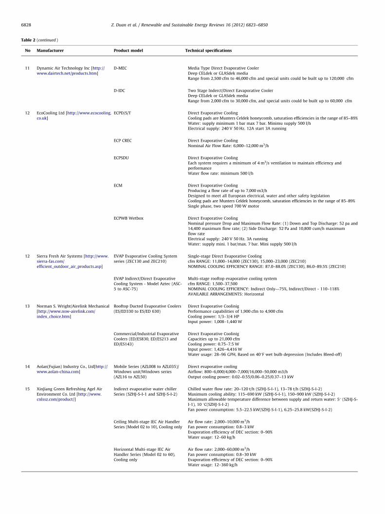
Table 2 (continued )
No Manufacturer Product model Technical specifications
11 Dynamic Air Technology Inc [http://
www.dairtech.net/products.htm]
D-MEC Media Type Direct Evaporative Cooler
Deep CELdek or GLASdek media
Range from 2,500 cfm to 46,000 cfm and special units could be built up to 120,000 cfm
D-IDC Two Stage Inderct/Direct Eavaporative Cooler
Deep CELdek or GLASdek media
Range from 2,000 cfm to 30,000 cfm, and special units could be built up to 60,000 cfm
12 EcoCooling Ltd [http://www.ecocooling.
co.uk]
ECPD/S/T Direct Evaporative Cooling
Cooling pads are Munters Celdek honeycomb, saturation efficiencies in the range of 85–89%
Water: supply minimum 1 bar max 7 bar. Minimu supply 500 l/h
Electrical supply: 240 V 50 Hz. 12A start 3A running
ECP CREC Direct Evaporative Cooling
Nominal Air Flow Rate: 6,000–12,000 m3/h
ECPSDU Direct Evaporative Cooling
Each system requires a minimum of 4 m3/s ventilation to maintain efficiency and
performance
Water flow rate: minimum 500 l/h
ECM Direct Evaporative Cooling
Producing a flow rate of up to 7,000 m3/h
Designed to meet all European electrical, water and other safety legislation
Cooling pads are Munters Celdek honeycomb, saturation efficiencies in the range of 85–89%
Single phase, two speed 700 W motor
ECPWB Wetbox Direct Evaporative Cooling
Nominal pressure Drop and Maximum Flow Rate: (1) Down and Top Discharge: 52 pa and
14,400 maximum flow rate; (2) Side Discharge: 52 Pa and 10,800 cum/h maximum
flow rate
Electrical supply: 240 V 50 Hz. 3A running
Water: supply mini. 1 bar/max. 7 bar. Mini supply 500 l/h
12 Sierra Fresh Air Systems [http://www.
sierra-fas.com/
efficient_outdoor_air_products.asp]
EVAP Evaporative Cooling System
series (ZEC130 and ZEC210)
Single-stage Direct Evaporative Cooling
cfm RANGE: 11,000–14,000 (ZEC130), 15,000–23,000 (ZEC210)
NOMINAL COOLING EFFICIENCY RANGE: 87.0–88.0% (ZEC130), 86.0–89.5% (ZEC210)
EVAP Indirect/Direct Evaporative
Cooling System - Model Aztec (ASC-
5 to ASC-75)
Multi-stage rooftop evaporative cooling system
cfm RANGE: 1,500–37,500
NOMINAL COOLING EFFICIENCY: Indirect Only—75%, Indirect/Direct - 110–118%
AVAILABLE ARRANGEMENTS: Horizontal
13 Norman S. Wright/Airelink Mechanical
[http://www.nsw-airelink.com/
index_choice.htm]
Rooftop Ducted Evaporative Coolers
(ES/ED330 to ES/ED 630)
Direct Evaporative Coolinig
Performance capabilities of 1,900 cfm to 4,900 cfm
Cooling power: 1/3–3/4 HP
Input power: 1,008–1,440 W
Commercial/Industrial Evaporative
Coolers (ED/ES830, ED/ES213 and
ED/ES143)
Direct Evaporative Coolinig
Capacities up to 21,000 cfm
Cooling power: 0.75–7.5 W
Input power: 1,426–4,416 W
Water usage: 28–96 GPH, Based on 401F wet bulb depression (Includes Bleed-off)
14 Aolan(Fujian) Industry Co., Ltd[http://
www.aolan-china.com]
Mobile Series (AZL008 to AZL035)/
Windows unit/Windows series
(AZL16 to AZL50)
Direct evaporative cooling
Airflow: 800–6,000/4,000–7,000/16,000–50,000 m3/h
Output cooling power: 0.02–0.55/0.06–0.25/0.37–13 kW
15 XinJiang Green Refreshing Agel Air
Environment Co. Ltd [http://www.
cnlssz.com/product/]
Indirect evaporative water chiller
Series (SZHJ-S-I-1 and SZHJ-S-I-2)
Chilled water flow rate: 20–120 t/h (SZHJ-S-I-1), 13–78 t/h (SZHJ-S-I-2)
Maximum cooling ability: 115–690 kW (SZHJ-S-I-1), 150–900 kW (SZHJ-S-I-2)
Maximum allowable temperature difference between supply and return water: 51 (SZHJ-S-
I-1), 10 1C(SZHJ-S-I-2)
Fan power consumption: 5.5–22.5 kW(SZHJ-S-I-1), 6.25–25.8 kW(SZHJ-S-I-2)
Ceiling Multi-stage IEC Air Handler
Series (Model 02 to 10), Cooling only
Air flow rate: 2,000–10,000 m3/h
Fan power consumption: 0.8–3 kW
Evaporation efficiency of DEC section: 0–90%
Water usage: 12–60 kg/h
Horizontal Multi-stage IEC Air
Handler Series (Model 02 to 60),
Cooling only
Air flow rate: 2,000–60,000 m3/h
Fan power consumption: 0.8–30 kW
Evaporation efficiency of DEC section: 0–90%
Water usage: 12–360 kg/h
Z. Duan et al. / Renewable and Sustainable Energy Reviews 16 (2012) 6823–68506828

Table 3The selected engineering project using IEC/DEC technologies.
No Project information
1 Project: Evaluation of an OASys Indirect-Direct Evaporative Cooler Retrofit [http://www.speakmancompany.com/files/15971]
Product Supplier: Speakman CRS
Project profile: Installed at 2006 in a Sacramento area PATH demonstration house. Before the OASys installation, the 43-year old house was air-conditioned
exclusively using a 5-ton AC system. The house also included an existing (but no longer functional) roof mounted evaporative cooler. SWA evaluated the drop-in
replacement of the existing evaporative cooler with the OASys, interviewing the HVAC contractor and homeowner and installing long term monitoring equipment
in order to quantify:
OASys and AC energy use
OASys cooling capacity over a range of outdoor conditions
Indoor house temperature and relative humidity
This evaluation effort was co-funded through the Building America Program and the Sacramento Municipal Utility District (SMUD). Results indicate that (1) The
cooling capacity of the OASys is comparable to that of a typical 2-ton AC system and (2) The Energy Efficiency Ratio (EER) of the OASys is roughly 3 times greater
than that of a SEER 14 AC system.
2 Project: Evaporative Cooling for Badwater, California [http://www.munters.us/upload/Related%20product%20files/
Evaporative%20Cooling%20for%20Badwater%20CA%20Case%20Study.pdf]
Product Supplier: Munters
Project profile: To meet ventilation requirements of the 2001 California Title 24 Energy Code as well as ASHRAE Standard 62-2001 both called for a minimum
outdoor air quantity of 1.5 cfm per square foot of auto shop floor space, a total outdoor air requirement of 18,000 cfm for the two shops is needed. With California’s
severe energy shortages in 2001, the decision was made to use an Indirect/Direct Evaporative Cooling Unit (IDEC) design rather than refrigeration. On a 1211F
design day, the two-stage evaporative cooling systems would deliver 681F to the conditioned space, allowing the indoor temperature to be maintained at 851F or
lower while introducing the code required outdoor air quantity. This system would consume only 0.2 kW per ton (kw/ton) of electrical energy for sensible cooling
of the space compared to the more conventional air-cooled refrigeration design which would require 1.2 kW/ton or worse at the higher ambient dry-bulb
conditions. Till October 8, 2005, the IEC/DEC equipment had completed three years of operation. It was noticed that the cadmium plated bolts had deteriorated to
the point that they crumbled as they were removed. After the panels were removed it was also determined that
the sump pump and the metal box surrounding the pump had considerable hardness deposits on the surfaces.
the scavanger side of the ABS plastic tubes were free of harmful deposits
the remainder of the equipment was clean and in like new condition
the equipment was operating as intended, delivering the cfm and temperature as specified.
3 Project: The Cooling of Green House Data
[http://www.coolerado.com/products-files/2011/casestudies/casestudy_greenhousedata.pdf]
Product Supplier: Coolerado
Project profile: Green House Data—a 100% wind powered data center in Cheyenne, Wyoming—began its business in 2008 with the mission to build a super-
energy-efficient client server and data storage system. Like every data center, Green House Data which was 2000 square footage with an upcoming add of 3,000
needed a reliable air conditioning system that would cool its server room 24 h a day, seven days a week—without fail. Traditional cooling methods would have
taken an enormous amount of energy throughout the year.
By using 14 Coolerado M50’s, in two years, Green House Data had reduced its cooling bill by 90% and had experienced an overall total energy reduction in the data
center of 40%. Besides providing Green House Data with a dramatic reduction in energy savings and an increase in sustainability, Coolerado also met the
company’s reliability needs. In addition, the modular installation system provided a critical backup option, so if an air conditioner needed to be taken offline, it
wouldn’t impact the servers or operation.
4 Project: Application of Dew Point Indirect Evaporative Cool Technique in Textile Mill
[Du Lei. Application of Dew Point Indirect Evaporative Cool Technique in Textile Mill. Progress in Textile Science & Technology. 2009, No. 3: 50–52]
Product Supplier: Unavailable
Project profile: As pre-cooling, combined with mechanical cooling system, the dew point indirect evaporative cooling technique was adopted in by a textile mill
with 1200 m2 in Shaoxing of Zhejiang province China. Through test and calculating, the dew point indirect evaporative cooling section could lower temperature 6–
8 1C and maintain room relative humidity between 70–85%. Complete fresh air could improve workshop air quality; the use of hybrid system could save energy
14% comparing to simple mechanism refrigeration air conditioning.
5 Project: Three Stages Evaporative Cooling in a functional building located in Karamay of Xinjiang Province China [Huang Xiang, Qu Yuan and Di Yuhui. Application
of multi-stage evaporative cooling air conditioning system to northwest China. HV & AC. 2004, Vol. 34, No.6: 67–71]
Product Supplier: XinJiang Green Refreshing Agel Air Environment Co. Ltd
Project profile:General information of this hospital building: (a) Floor No: 13 in total; (b) Area: 2,000 m2; (c) Room type: Lecture room and lounge hall
Air conditioning system: (a) Model: SZHJ-III-50; (b) 3 stages evaporative air conditioning system (IECþ IECþDEC); (c) Air flow rate: 5000 m3/h; (d) Design
sensible cooling load: 700 kW;(e) Date of start in operation: July 2001
Operation performance test and conclusions
Time: 15:52–17:54
Date: 12/August/2001
Test results: outdoor air 36 1C db/20 1C wb; supply air: 15.5 1C db/14.5 1C wb
6 Project: Indirect-Direct Evaporative Cooling at McCarran Airport, Las Vegas Nevada
[http://www.swenergy.org/events/evaporative/Summary.pdf]
Product Supplier: Des Champs Technologies
Project profile: Des Champs Technologies developed an indirect evaporative cooling system for the McCarran
Airport Terminal in Las Vegas, Nevada. The system consists of 15 Des Champs IDEC units ranging in size from 8,000 cfm to 28,000 cfm, for a total of 280,000 cfm of
equipment. The IEC system uses an EPX polymer heat exchanger that resists mineral buildup, which is a major challenge to the use of evaporative cooling in Las Vegas
because of hard water conditions. The Des Champs system provides cold supply air with an EER of 42, which is much more efficient than refrigeration based systems.
7 Project: Pharmaceutical Warehouse
[http://www.ecocooling.ie/casestudies.pdf]Product Supplier: Ecocooling
Project profile: Merck Sante, based in the French city of Orleans, manufactures and distributes pharmaceutical products. Their main warehouse is required to
operate under the conditions of ‘controlled room temperature’ which for their range of products is less than 250 1C. Eighteen down discharge EcoCooling
Z. Duan et al. / Renewable and Sustainable Energy Reviews 16 (2012) 6823–6850 6829
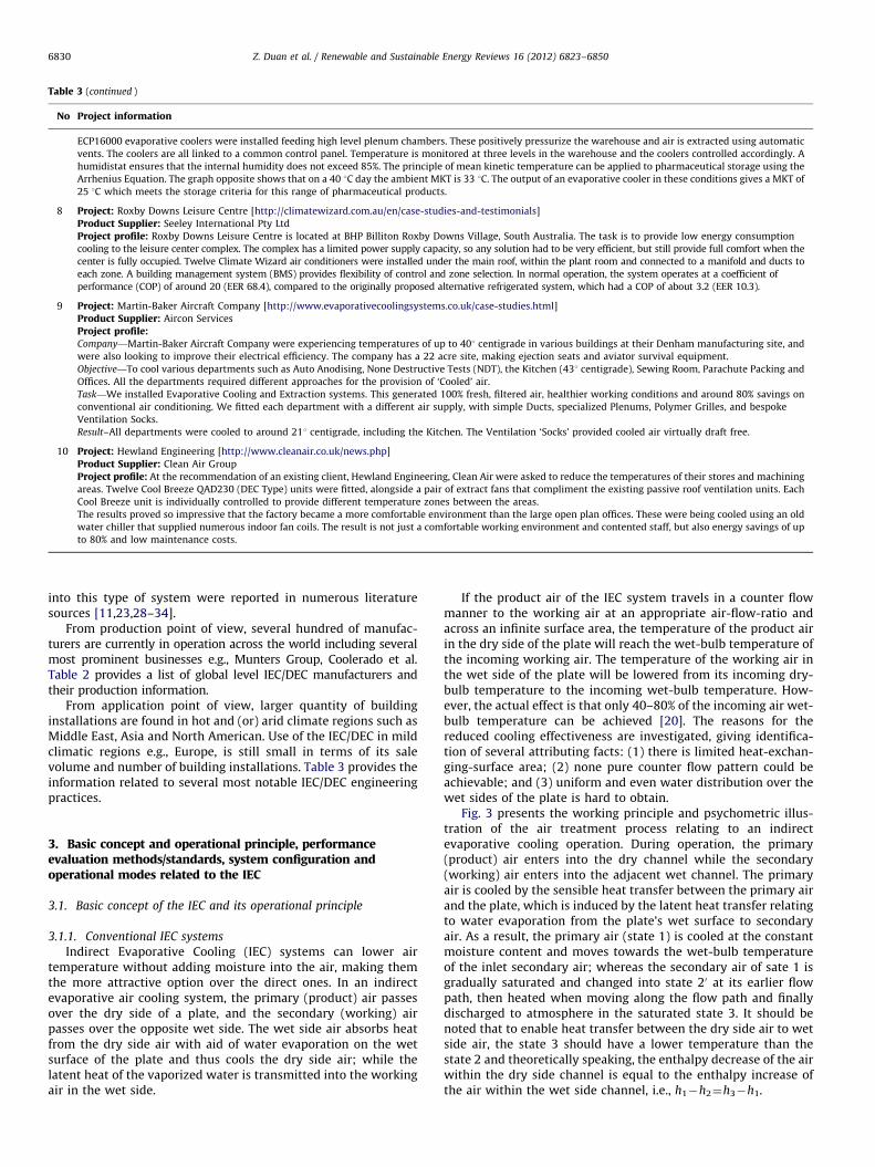
Table 3 (continued )
No Project information
ECP16000 evaporative coolers were installed feeding high level plenum chambers. These positively pressurize the warehouse and air is extracted using automatic
vents. The coolers are all linked to a common control panel. Temperature is monitored at three levels in the warehouse and the coolers controlled accordingly. A
humidistat ensures that the internal humidity does not exceed 85%. The principle of mean kinetic temperature can be applied to pharmaceutical storage using the
Arrhenius Equation. The graph opposite shows that on a 40 1C day the ambient MKT is 33 1C. The output of an evaporative cooler in these conditions gives a MKT of
25 1C which meets the storage criteria for this range of pharmaceutical products.
8 Project: Roxby Downs Leisure Centre [http://climatewizard.com.au/en/case-studies-and-testimonials]
Product Supplier: Seeley International Pty Ltd
Project profile: Roxby Downs Leisure Centre is located at BHP Billiton Roxby Downs Village, South Australia. The task is to provide low energy consumption
cooling to the leisure center complex. The complex has a limited power supply capacity, so any solution had to be very efficient, but still provide full comfort when the
center is fully occupied. Twelve Climate Wizard air conditioners were installed under the main roof, within the plant room and connected to a manifold and ducts to
each zone. A building management system (BMS) provides flexibility of control and zone selection. In normal operation, the system operates at a coefficient of
performance (COP) of around 20 (EER 68.4), compared to the originally proposed alternative refrigerated system, which had a COP of about 3.2 (EER 10.3).
9 Project: Martin-Baker Aircraft Company [http://www.evaporativecoolingsystems.co.uk/case-studies.html]
Product Supplier: Aircon Services
Project profile:Company—Martin-Baker Aircraft Company were experiencing temperatures of up to 401 centigrade in various buildings at their Denham manufacturing site, and
were also looking to improve their electrical efficiency. The company has a 22 acre site, making ejection seats and aviator survival equipment.
Objective—To cool various departments such as Auto Anodising, None Destructive Tests (NDT), the Kitchen (431 centigrade), Sewing Room, Parachute Packing and
Offices. All the departments required different approaches for the provision of ‘Cooled’ air.
Task—We installed Evaporative Cooling and Extraction systems. This generated 100% fresh, filtered air, healthier working conditions and around 80% savings on
conventional air conditioning. We fitted each department with a different air supply, with simple Ducts, specialized Plenums, Polymer Grilles, and bespoke
Ventilation Socks.
Result–All departments were cooled to around 211 centigrade, including the Kitchen. The Ventilation ‘Socks’ provided cooled air virtually draft free.
10 Project: Hewland Engineering [http://www.cleanair.co.uk/news.php]
Product Supplier: Clean Air Group
Project profile: At the recommendation of an existing client, Hewland Engineering, Clean Air were asked to reduce the temperatures of their stores and machining
areas. Twelve Cool Breeze QAD230 (DEC Type) units were fitted, alongside a pair of extract fans that compliment the existing passive roof ventilation units. Each
Cool Breeze unit is individually controlled to provide different temperature zones between the areas.
The results proved so impressive that the factory became a more comfortable environment than the large open plan offices. These were being cooled using an old
water chiller that supplied numerous indoor fan coils. The result is not just a comfortable working environment and contented staff, but also energy savings of up
to 80% and low maintenance costs.
Z. Duan et al. / Renewable and Sustainable Energy Reviews 16 (2012) 6823–68506830
into this type of system were reported in numerous literaturesources [11,23,28–34].
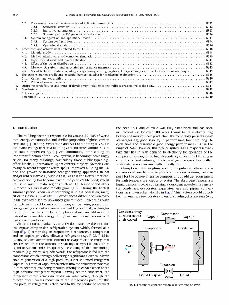
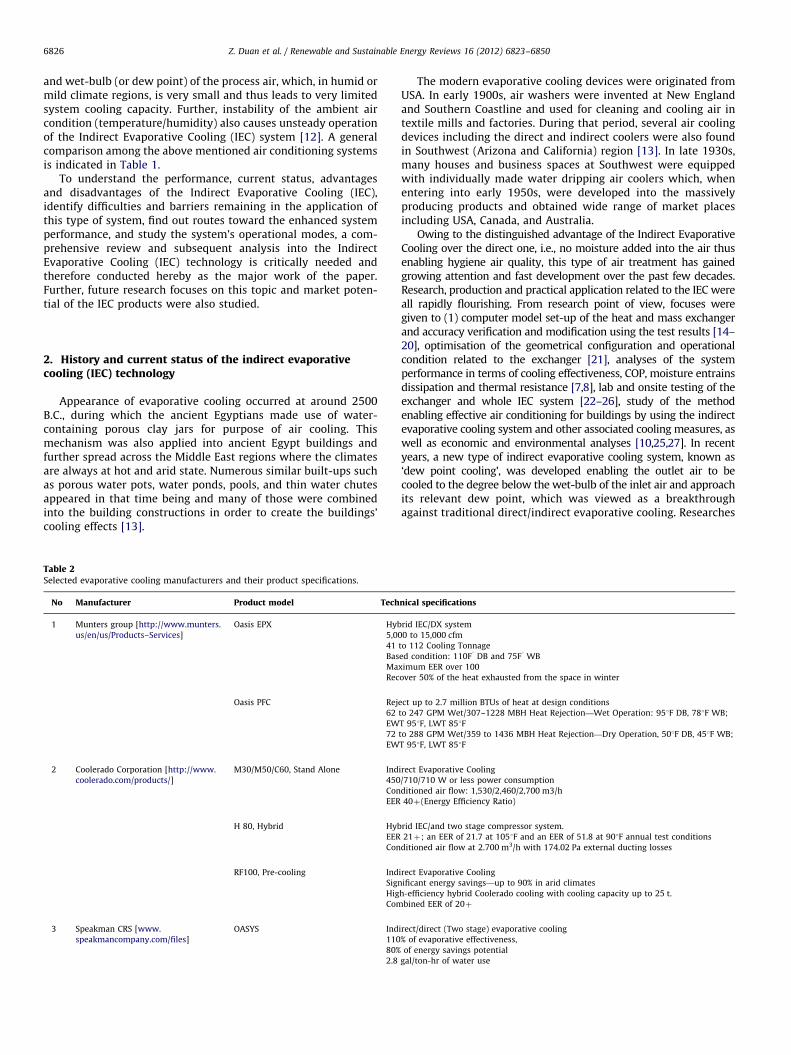
From production point of view, several hundred of manufac-turers are currently in operation across the world including severalmost prominent businesses e.g., Munters Group, Coolerado et al.Table 2 provides a list of global level IEC/DEC manufacturers andtheir production information.
From application point of view, larger quantity of buildinginstallations are found in hot and (or) arid climate regions such asMiddle East, Asia and North American. Use of the IEC/DEC in mildclimatic regions e.g., Europe, is still small in terms of its salevolume and number of building installations. Table 3 provides theinformation related to several most notable IEC/DEC engineeringpractices.
3. Basic concept and operational principle, performanceevaluation methods/standards, system configuration andoperational modes related to the IEC
3.1. Basic concept of the IEC and its operational principle
3.1.1. Conventional IEC systems
Indirect Evaporative Cooling (IEC) systems can lower airtemperature without adding moisture into the air, making themthe more attractive option over the direct ones. In an indirectevaporative air cooling system, the primary (product) air passesover the dry side of a plate, and the secondary (working) airpasses over the opposite wet side. The wet side air absorbs heatfrom the dry side air with aid of water evaporation on the wetsurface of the plate and thus cools the dry side air; while thelatent heat of the vaporized water is transmitted into the workingair in the wet side.
If the product air of the IEC system travels in a counter flowmanner to the working air at an appropriate air-flow-ratio andacross an infinite surface area, the temperature of the product airin the dry side of the plate will reach the wet-bulb temperature ofthe incoming working air. The temperature of the working air inthe wet side of the plate will be lowered from its incoming dry-bulb temperature to the incoming wet-bulb temperature. How-ever, the actual effect is that only 40–80% of the incoming air wet-bulb temperature can be achieved [20]. The reasons for thereduced cooling effectiveness are investigated, giving identifica-tion of several attributing facts: (1) there is limited heat-exchan-ging-surface area; (2) none pure counter flow pattern could beachievable; and (3) uniform and even water distribution over thewet sides of the plate is hard to obtain.
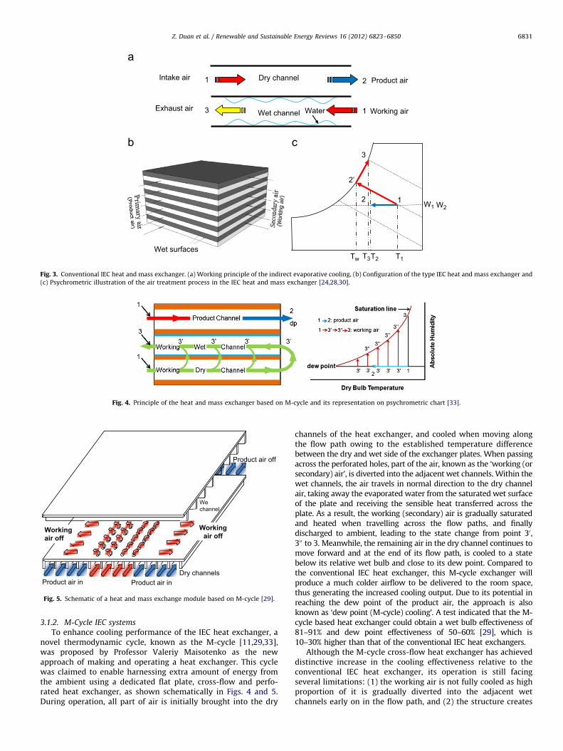
Fig. 3 presents the working principle and psychometric illus-tration of the air treatment process relating to an indirectevaporative cooling operation. During operation, the primary(product) air enters into the dry channel while the secondary(working) air enters into the adjacent wet channel. The primaryair is cooled by the sensible heat transfer between the primary airand the plate, which is induced by the latent heat transfer relatingto water evaporation from the plate’s wet surface to secondaryair. As a result, the primary air (state 1) is cooled at the constantmoisture content and moves towards the wet-bulb temperatureof the inlet secondary air; whereas the secondary air of sate 1 isgradually saturated and changed into state 20 at its earlier flowpath, then heated when moving along the flow path and finallydischarged to atmosphere in the saturated state 3. It should benoted that to enable heat transfer between the dry side air to wetside air, the state 3 should have a lower temperature than thestate 2 and theoretically speaking, the enthalpy decrease of the airwithin the dry side channel is equal to the enthalpy increase ofthe air within the wet side channel, i.e., h1�h2¼h3�h1.
1 2 Product airIntake air
3 1 Working airExhaust air
Dry channel
Wet channel Water
Wet surfaces T2Tw
W21 W1
2
T1
3
T3
2’
Fig. 3. Conventional IEC heat and mass exchanger. (a) Working principle of the indirect evaporative cooling, (b) Configuration of the type IEC heat and mass exchanger and
(c) Psychrometric illustration of the air treatment process in the IEC heat and mass exchanger [24,28,30].
Fig. 4. Principle of the heat and mass exchanger based on M-cycle and its representation on psychrometric chart [33].
Dry channelsProduct air inProduct air in
Workingair off
Product air off
Wechannel
Workingair off
Fig. 5. Schematic of a heat and mass exchange module based on M-cycle [29].
Z. Duan et al. / Renewable and Sustainable Energy Reviews 16 (2012) 6823–6850 6831
3.1.2. M-Cycle IEC systems
To enhance cooling performance of the IEC heat exchanger, anovel thermodynamic cycle, known as the M-cycle [11,29,33],was proposed by Professor Valeriy Maisotenko as the newapproach of making and operating a heat exchanger. This cyclewas claimed to enable harnessing extra amount of energy fromthe ambient using a dedicated flat plate, cross-flow and perfo-rated heat exchanger, as shown schematically in Figs. 4 and 5.During operation, all part of air is initially brought into the dry
channels of the heat exchanger, and cooled when moving alongthe flow path owing to the established temperature differencebetween the dry and wet side of the exchanger plates. When passingacross the perforated holes, part of the air, known as the ‘working (orsecondary) air’, is diverted into the adjacent wet channels. Within thewet channels, the air travels in normal direction to the dry channelair, taking away the evaporated water from the saturated wet surfaceof the plate and receiving the sensible heat transferred across theplate. As a result, the working (secondary) air is gradually saturatedand heated when travelling across the flow paths, and finallydischarged to ambient, leading to the state change from point 30,300 to 3. Meanwhile, the remaining air in the dry channel continues tomove forward and at the end of its flow path, is cooled to a statebelow its relative wet bulb and close to its dew point. Compared tothe conventional IEC heat exchanger, this M-cycle exchanger willproduce a much colder airflow to be delivered to the room space,thus generating the increased cooling output. Due to its potential inreaching the dew point of the product air, the approach is alsoknown as ‘dew point (M-cycle) cooling’. A test indicated that the M-cycle based heat exchanger could obtain a wet bulb effectiveness of81–91% and dew point effectiveness of 50–60% [29], which is10–30% higher than that of the conventional IEC heat exchangers.
Although the M-cycle cross-flow heat exchanger has achieveddistinctive increase in the cooling effectiveness relative to theconventional IEC heat exchanger, its operation is still facingseveral limitations: (1) the working air is not fully cooled as highproportion of it is gradually diverted into the adjacent wetchannels early on in the flow path, and (2) the structure creates
Dry Bulb Temperature
Saturation Line
Abs
olut
e H
umid
ity
12
3
dp3’
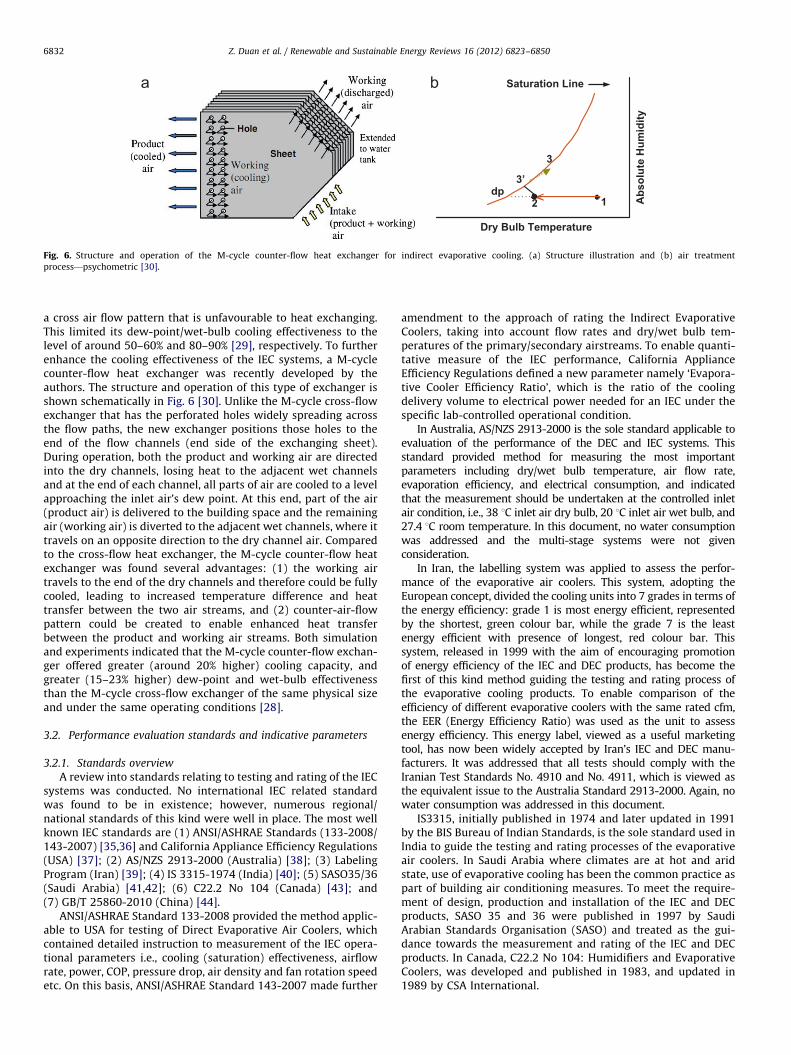
Fig. 6. Structure and operation of the M-cycle counter-flow heat exchanger for indirect evaporative cooling. (a) Structure illustration and (b) air treatment
process—psychometric [30].
Z. Duan et al. / Renewable and Sustainable Energy Reviews 16 (2012) 6823–68506832
a cross air flow pattern that is unfavourable to heat exchanging.This limited its dew-point/wet-bulb cooling effectiveness to thelevel of around 50–60% and 80–90% [29], respectively. To furtherenhance the cooling effectiveness of the IEC systems, a M-cyclecounter-flow heat exchanger was recently developed by theauthors. The structure and operation of this type of exchanger isshown schematically in Fig. 6 [30]. Unlike the M-cycle cross-flowexchanger that has the perforated holes widely spreading acrossthe flow paths, the new exchanger positions those holes to theend of the flow channels (end side of the exchanging sheet).During operation, both the product and working air are directedinto the dry channels, losing heat to the adjacent wet channelsand at the end of each channel, all parts of air are cooled to a levelapproaching the inlet air’s dew point. At this end, part of the air(product air) is delivered to the building space and the remainingair (working air) is diverted to the adjacent wet channels, where ittravels on an opposite direction to the dry channel air. Comparedto the cross-flow heat exchanger, the M-cycle counter-flow heatexchanger was found several advantages: (1) the working airtravels to the end of the dry channels and therefore could be fullycooled, leading to increased temperature difference and heattransfer between the two air streams, and (2) counter-air-flowpattern could be created to enable enhanced heat transferbetween the product and working air streams. Both simulationand experiments indicated that the M-cycle counter-flow exchan-ger offered greater (around 20% higher) cooling capacity, andgreater (15–23% higher) dew-point and wet-bulb effectivenessthan the M-cycle cross-flow exchanger of the same physical sizeand under the same operating conditions [28].
3.2. Performance evaluation standards and indicative parameters
3.2.1. Standards overview
A review into standards relating to testing and rating of the IECsystems was conducted. No international IEC related standardwas found to be in existence; however, numerous regional/national standards of this kind were well in place. The most wellknown IEC standards are (1) ANSI/ASHRAE Standards (133-2008/143-2007) [35,36] and California Appliance Efficiency Regulations(USA) [37]; (2) AS/NZS 2913-2000 (Australia) [38]; (3) LabelingProgram (Iran) [39]; (4) IS 3315-1974 (India) [40]; (5) SASO35/36(Saudi Arabia) [41,42]; (6) C22.2 No 104 (Canada) [43]; and(7) GB/T 25860-2010 (China) [44].
ANSI/ASHRAE Standard 133-2008 provided the method applic-able to USA for testing of Direct Evaporative Air Coolers, whichcontained detailed instruction to measurement of the IEC opera-tional parameters i.e., cooling (saturation) effectiveness, airflowrate, power, COP, pressure drop, air density and fan rotation speedetc. On this basis, ANSI/ASHRAE Standard 143-2007 made further
amendment to the approach of rating the Indirect EvaporativeCoolers, taking into account flow rates and dry/wet bulb tem-peratures of the primary/secondary airstreams. To enable quanti-tative measure of the IEC performance, California ApplianceEfficiency Regulations defined a new parameter namely ‘Evapora-tive Cooler Efficiency Ratio’, which is the ratio of the coolingdelivery volume to electrical power needed for an IEC under thespecific lab-controlled operational condition.
In Australia, AS/NZS 2913-2000 is the sole standard applicable toevaluation of the performance of the DEC and IEC systems. Thisstandard provided method for measuring the most importantparameters including dry/wet bulb temperature, air flow rate,evaporation efficiency, and electrical consumption, and indicatedthat the measurement should be undertaken at the controlled inletair condition, i.e., 38 1C inlet air dry bulb, 20 1C inlet air wet bulb, and27.4 1C room temperature. In this document, no water consumptionwas addressed and the multi-stage systems were not givenconsideration.
In Iran, the labelling system was applied to assess the perfor-mance of the evaporative air coolers. This system, adopting theEuropean concept, divided the cooling units into 7 grades in terms ofthe energy efficiency: grade 1 is most energy efficient, representedby the shortest, green colour bar, while the grade 7 is the leastenergy efficient with presence of longest, red colour bar. Thissystem, released in 1999 with the aim of encouraging promotionof energy efficiency of the IEC and DEC products, has become thefirst of this kind method guiding the testing and rating process ofthe evaporative cooling products. To enable comparison of theefficiency of different evaporative coolers with the same rated cfm,the EER (Energy Efficiency Ratio) was used as the unit to assessenergy efficiency. This energy label, viewed as a useful marketingtool, has now been widely accepted by Iran’s IEC and DEC manu-facturers. It was addressed that all tests should comply with theIranian Test Standards No. 4910 and No. 4911, which is viewed asthe equivalent issue to the Australia Standard 2913-2000. Again, nowater consumption was addressed in this document.
IS3315, initially published in 1974 and later updated in 1991by the BIS Bureau of Indian Standards, is the sole standard used inIndia to guide the testing and rating processes of the evaporativeair coolers. In Saudi Arabia where climates are at hot and aridstate, use of evaporative cooling has been the common practice aspart of building air conditioning measures. To meet the require-ment of design, production and installation of the IEC and DECproducts, SASO 35 and 36 were published in 1997 by SaudiArabian Standards Organisation (SASO) and treated as the gui-dance towards the measurement and rating of the IEC and DECproducts. In Canada, C22.2 No 104: Humidifiers and EvaporativeCoolers, was developed and published in 1983, and updated in1989 by CSA International.
Z. Duan et al. / Renewable and Sustainable Energy Reviews 16 (2012) 6823–6850 6833
In China, the first IEC/DEC standard namely, GB/T 25860-2010Evaporative Air Cooler, was developed in 2010. This standardaddressed various issues related to the IEC/DEC including terms,definitions, types, requirements, testing procedures, signs, packa-ging, transportation and storage. It is considered as the legaldocument applicable to the IEC/DEC related productions andbuilding installations.
3.2.2. Indicative parameters
Review of the IEC/DEC standards indicated that the perfor-mance of an IEC system could be represented by several char-acteristic parameters including (1) wet-bulb or dew pointeffectiveness; (2) evaporative cooler efficiency ratio; (3) coolingcapacity; (4) power consumption; (5) energy efficiency; (6) waterevaporation rate; (7) secondary-to-primary air ratio; (8) pressureloss; and (9) air flow rate. These are detailed as follows:
(1)
Wet-bulb (dew-point) effectivenessWet-bulb effectiveness is a parameter describing the extent ofthe approach of the outlet product air temperature of the IECagainst the wet-bulb temperature of the inlet working air, andcan be written as:ewb ¼tp,db,in�tp,db,out
tp,db,in�tp,wb,inð1Þ
Dew point effectiveness is another parameter used for thispurpose and defined as the ratio of the temperature differencebetween the inlet and outlet product air to the differencebetween the inlet product air’s dry bulb and inlet workingair’s dew point temperature. This reflects the extent of theapproach of the outlet product air temperature againstthe dew point temperature of the inlet working air relatedto the IEC, shown as follows:
edp ¼tp,db,in�tp,db,out
tp,db,in�tp,db,inð2Þ
It should be addressed that the dew point effectiveness isparticularly suitable for use in recently emerging dew pointsystem, an innovative form of IEC configuration.
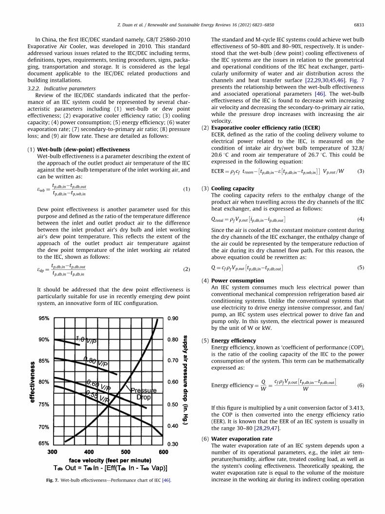
Fig. 7. Wet-bulb effectiveness—Performance chart of IEC [46].
The standard and M-cycle IEC systems could achieve wet bulbeffectiveness of 50–80% and 80–90%, respectively. It is under-stood that the wet-bulb (dew point) cooling effectiveness ofthe IEC systems are the issues in relation to the geometricaland operational conditions of the IEC heat exchanger, parti-cularly uniformity of water and air distribution across thechannels and heat transfer surface [22,29,30,45,46]. Fig. 7presents the relationship between the wet-bulb effectivenessand associated operational parameters [46]. The wet-bulbeffectiveness of the IEC is found to decrease with increasingair velocity and decreasing the secondary-to-primary air ratio,while the pressure drop increases with increasing the airvelocity.
(2)
Evaporative cooler efficiency ratio (ECER)ECER, defined as the ratio of the cooling delivery volume toelectrical power related to the IEC, is measured on thecondition of intake air dry/wet bulb temperature of 32.8/20.6 1C and room air temperature of 26.7 1C. This could beexpressed in the following equation:ECER¼ rf cf troom� tp,db,in�e tp,db,in�tp,wb,in
� �� �� �Vp,out=W ð3Þ
(3)
Cooling capacityThe cooling capacity refers to the enthalpy change of theproduct air when travelling across the dry channels of the IECheat exchanger, and is expressed as follows:Qtotal ¼ rf Vp,out ip,db,in�ip,db,out
� �ð4Þ
Since the air is cooled at the constant moisture content duringthe dry channels of the IEC exchanger, the enthalpy change ofthe air could be represented by the temperature reduction ofthe air during its dry channel flow path. For this reason, theabove equation could be rewritten as:
Q ¼ cfrf Vp,out tp,db,in�tp,db,out
� �ð5Þ
(4)
Power consumptionAn IEC system consumes much less electrical power thanconventional mechanical compression refrigeration based airconditioning systems. Unlike the conventional systems thatuse electricity to drive energy intensive compressor, and fan/pump, an IEC system uses electrical power to drive fan andpump only. In this system, the electrical power is measuredby the unit of W or kW.(5)
Energy efficiencyEnergy efficiency, known as ‘coefficient of performance (COP),is the ratio of the cooling capacity of the IEC to the powerconsumption of the system. This term can be mathematicallyexpressed as:Energy efficiency¼Q
W¼
cfrf Vp,out tp,db,in�tp,db,out
� �
Wð6Þ
If this figure is multiplied by a unit conversion factor of 3.413,the COP is then converted into the energy efficiency ratio(EER). It is known that the EER of an IEC system is usually inthe range 30–80 [28,29,47].
(6)
Water evaporation rateThe water evaporation rate of an IEC system depends upon anumber of its operational parameters, e.g., the inlet air tem-perature/humidity, airflow rate, treated cooling load, as well asthe system’s cooling effectiveness. Theoretically speaking, thewater evaporation rate is equal to the volume of the moistureincrease in the working air during its indirect cooling operation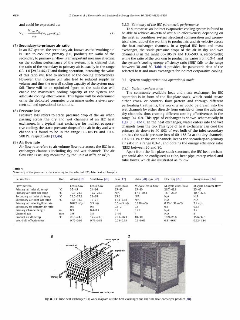
TablSum
Pa
Flo
Pr
Pr
Se
Se
Pr
Se
Pr
Ch
Pr
W
Z. Duan et al. / Renewable and Sustainable Energy Reviews 16 (2012) 6823–68506834
and could be expressed as:
Vw ¼Vs,outrs,f
rw
ðws,out�ws,inÞ ð7Þ
(7)
Secondary-to-primary air ratioIn an IEC system, the secondary air, known as the ‘working air’is used to cool the primary (i.e., product) air. Ratio of thesecondary to primary air-flow is an important measure effectingon the cooling performance of the system. It is claimed thatthe ratio of the secondary to primary air is usually in the range0.3–1.0 [29,34,46,47] and during operation, increasing the valueof this ratio will lead to increase of the cooling effectiveness.However, this increase will also lead to reduced supply airvolume and thus the overall cooling capacity of the system mayfall. There will be an optimised figure on the ratio that willenable the maximised cooling capacity of the system andadequate cooling effectiveness. This figure will be determinedusing the dedicated computer programme under a given geo-metrical and operational conditions.(8)
Pressure lossPressure loss refers to static pressure drop of the air whenpassing across the dry and wet channels of an IEC heatexchanger. In a typical heat exchanger for indirect evapora-tive cooling, the static pressure drops of the air in dry and wetchannels is found to be in the range 60–185 Pa and 100–500 Pa, respectively [13,46].(9)
Air flow rateAir flow rate refers to air volume flow rate across the IEC heatexchanger channels including dry and wet channels. The airflow rate is usually measured by the unit of m3/s or m3/h.e 4mary of the parametric data relating to the selected IEC plate heat exchangers.
rameters Unit Alonso [19] Stoitchkov [20] Guo
w pattern Cross-flow Cross-flow Cross
imary air inlet db temp 1C 35–45 24–36 25–4
imary air inlet wb temp 1C 19.5–23.3 17.7–28.3 N/A
condary air inlet db temp 1C 23.5–27.2 22–28 25.0
condary air inlet wb temp 1C 16.8–18.6 16–21 11.4–
imary air velocity/flow rate 0.022 m3/s 3.3 m/s 0.5–4
condary to primary air ratio 0.5 0.5 0.5–2
imary Channel length m 0.3 0.4–0.7 0.2
annel gap mm 3.0 3.5 2–10
oduct air db temp 1C 20.8–24.8 17.2–23.6 21.3–
et-bulb effectiveness 0.77–0.93 0.79–0.88 0.78–
Fig. 8. IEC Tube heat exchanger: (a) work diagram of tube he
3.2.3. Summary of the IEC parametric performance
To summarise, an indirect evaporative cooling system is found tobe able to achieve 40–90% of wet bulb effectiveness, depending onthe inlet air condition, system structural configuration and geome-trical size, ratio of the working to product air, and air velocity acrossthe heat exchanger channels. In a typical IEC heat and massexchanger, the static pressure drops of the air in dry and wetchannels is in the range 60–185 Pa and 100–500 Pa, respectively;while the ratio of the working to product air varies from 0.3–1, andthe system’s cooling energy efficiency ratio (EER) falls to the rangebetween 30 and 80. Table 4 provides the parametric data of theselected heat and mass exchangers for indirect evaporative cooling.
3.3. System configuration and operational mode
3.3.1. System configuration
The commonly available heat and mass exchanger for IECoperation is in form of the flat-plate-stack, which could createeither cross- or counter- flow pattern and through differentperforating treatments, the working air could be drawn into thewet channels by either directly from outside or from the adjacentdry channels, thus creating different cooling effectiveness in therange 0.4–0.9. This type of exchanger is shown schematically inFigs. 3, 5 and 6. In the heat exchanger, water enters into the wetchannels from the top. This type of heat exchanger can cool theprimary air down to 40–90% of wet-bulb of the inlet secondaryair, has the static pressure loss of 60–185 Pa at the dry channels,100–500 Pa at the wet channels, keeps the secondary-to-primaryair ratio in a range 0.3–1, and obtains the energy efficiency ratio(EER) between 30 and 80.
Apart from the flat-plate-stack structure, the IEC heat exchan-ger could also be configured as tube, heat pipe, rotary wheel andtube forms, which are illustrated as follow:
[47] Zhan [28], Qiu [22] Elberling [29] Riangvilaikul [24]
-flow M-cycle cross-flow M-cycle cross-flow M-cycle Counter-flow
5 25–40 26.7–43.8 25–45
17.9–30.3 18.1–23.9 10.7–32.5
N/A N/A N/A
23.8 N/A N/A N/A
.5 m/s 0.036 m3/s 0.53–1.38 m3/s 2.4 m/s
0.5 0.5 0.33
0.25 N/A 1.2
4 N/A 5
26.3 18–30 19.9–25.6 15.6–32.1
0.95 0.5–0.65 0.81–0.91 0.92–1.14
at exchanger and (b) tube heat exchanger product [48].
Z. Duan et al. / Renewable and Sustainable Energy Reviews 16 (2012) 6823–6850 6835
(1)
Tube structured IEC systemsFig. 8 presents a tube-based IEC heat exchanger invented byVelasco Gomez et al. [48]. This structure allows the primary airto flow through the internal tubing space on its length direction,and the second air to sweep across the external surface of thetubes in the normal direction to the primary air. Meanwhile, thewater is sprayed over the external surface of the tubes from thetop. This exchanger is claimed to be able to obtain more uniformwater films on the outer surface of the tubes and thus reducedair flow resistance than the flat-plate-stack structure.In this structure, the tubes are made of either polymer, metal,porous ceramic, or PVC. Over the recent years, the hydrophilicaluminium tubes with wall thickness of 0.02–0.06 mm weregradually applied in this process owing to their several dis-tinctive advantages, e.g., high thermal conductivity, low cost,and capability of forming the uniform water film. The newapproach for treating the aluminium tubes was to wrap a thinlayer of water affinity material (e.g., cotton, polyester fibre,special fibre, metallic wick, stainless steel mesh) to the outersurface of the tubes [44], which has been proven to be effectivein improving its water uniformity over the surface and thusenhancing the cooling effectiveness of the IEC. Porous ceramics,owing to the large specific surface area, excellent water retain-ing capacity and superior mechanical strength, were also foundto be the favourite materials for making tubes. During thisprocess, a non-permeable membrane is normally attached tothe inner surface of the porous ceramic tubes to preventmoisture transfer across the tube walls.The second tube-based IEC heat exchanger is shown schemati-cally in Fig. 9 [48]. In this structure, the primary air sweepsacross the outer surface of the tubes while the secondary airflows through the inner space of the tubes. The wall of the tubes,made of the thin porous layer, is designed to retain the spraywater which helps transfer heat between the primary andsecondary airstreams, through evaporation of water reservedin the porous media. The diffusion of the water from the poresto the air depends upon the permeability of the porous wall.This structure is claimed to be able to obtain an improvedcooling effectiveness over the one in Fig. 8 and its wet-bulbeffectiveness is in the range 40–80%.(2)
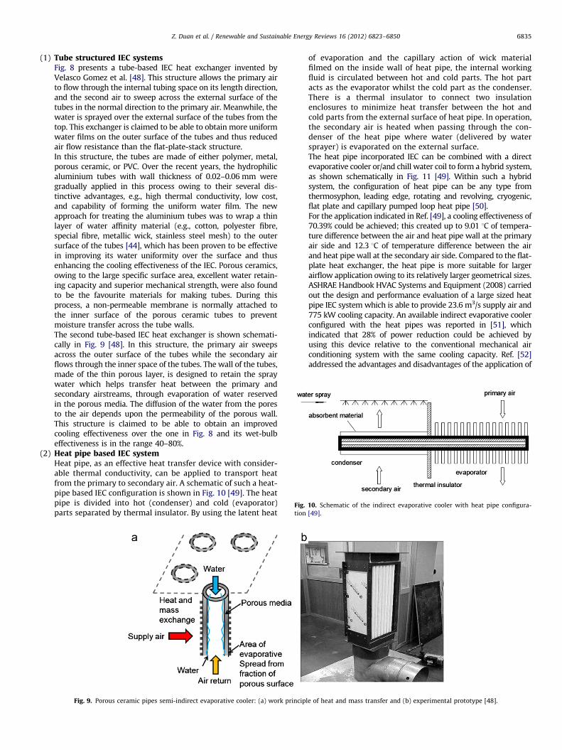
Fig. 10. Schematic of the indirect evaporative cooler with heat pipe configura-
tion [49].
Heat pipe based IEC systemHeat pipe, as an effective heat transfer device with consider-able thermal conductivity, can be applied to transport heatfrom the primary to secondary air. A schematic of such a heat-pipe based IEC configuration is shown in Fig. 10 [49]. The heatpipe is divided into hot (condenser) and cold (evaporator)parts separated by thermal insulator. By using the latent heat
Fig. 9. Porous ceramic pipes semi-indirect evaporative cooler: (a) work principl
of evaporation and the capillary action of wick materialfilmed on the inside wall of heat pipe, the internal workingfluid is circulated between hot and cold parts. The hot partacts as the evaporator whilst the cold part as the condenser.There is a thermal insulator to connect two insulationenclosures to minimize heat transfer between the hot andcold parts from the external surface of heat pipe. In operation,the secondary air is heated when passing through the con-denser of the heat pipe where water (delivered by watersprayer) is evaporated on the external surface.The heat pipe incorporated IEC can be combined with a directevaporative cooler or/and chill water coil to form a hybrid system,as shown schematically in Fig. 11 [49]. Within such a hybridsystem, the configuration of heat pipe can be any type fromthermosyphon, leading edge, rotating and revolving, cryogenic,flat plate and capillary pumped loop heat pipe [50].For the application indicated in Ref. [49], a cooling effectiveness of70.39% could be achieved; this created up to 9.01 1C of tempera-ture difference between the air and heat pipe wall at the primaryair side and 12.3 1C of temperature difference between the airand heat pipe wall at the secondary air side. Compared to the flat-plate heat exchanger, the heat pipe is more suitable for largerairflow application owing to its relatively larger geometrical sizes.ASHRAE Handbook HVAC Systems and Equipment (2008) carriedout the design and performance evaluation of a large sized heatpipe IEC system which is able to provide 23.6 m3/s supply air and775 kW cooling capacity. An available indirect evaporative coolerconfigured with the heat pipes was reported in [51], whichindicated that 28% of power reduction could be achieved byusing this device relative to the conventional mechanical airconditioning system with the same cooling capacity. Ref. [52]addressed the advantages and disadvantages of the application of
e of heat and mass transfer and (b) experimental prototype [48].
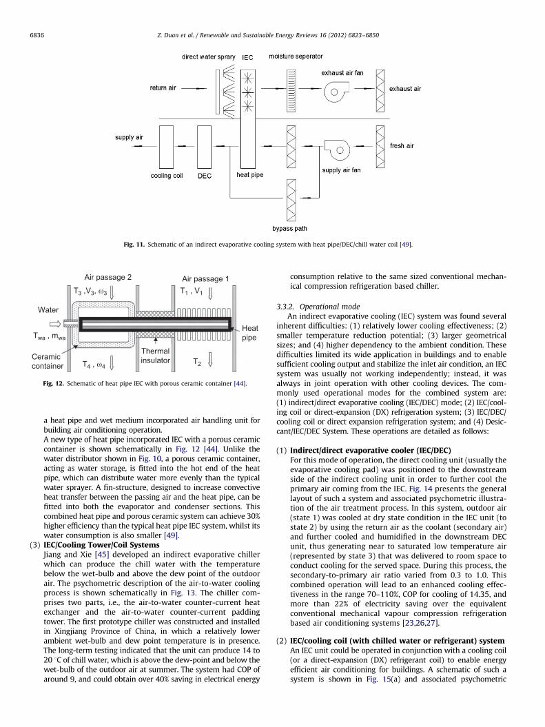
Fig. 11. Schematic of an indirect evaporative cooling system with heat pipe/DEC/chill water coil [49].
Air passage 2 Air passage 1 T3 ,V3, ω3
T4 , ω4
T1 , V1
T2
Water
Twa , mwa
Ceramiccontainer
Thermalinsulator
Heatpipe
Fig. 12. Schematic of heat pipe IEC with porous ceramic container [44].
Z. Duan et al. / Renewable and Sustainable Energy Reviews 16 (2012) 6823–68506836
a heat pipe and wet medium incorporated air handling unit forbuilding air conditioning operation.A new type of heat pipe incorporated IEC with a porous ceramiccontainer is shown schematically in Fig. 12 [44]. Unlike thewater distributor shown in Fig. 10, a porous ceramic container,acting as water storage, is fitted into the hot end of the heatpipe, which can distribute water more evenly than the typicalwater sprayer. A fin-structure, designed to increase convectiveheat transfer between the passing air and the heat pipe, can befitted into both the evaporator and condenser sections. Thiscombined heat pipe and porous ceramic system can achieve 30%higher efficiency than the typical heat pipe IEC system, whilst itswater consumption is also smaller [49].
(3)
IEC/Cooling Tower/Coil SystemsJiang and Xie [45] developed an indirect evaporative chillerwhich can produce the chill water with the temperaturebelow the wet-bulb and above the dew point of the outdoorair. The psychometric description of the air-to-water coolingprocess is shown schematically in Fig. 13. The chiller com-prises two parts, i.e., the air-to-water counter-current heatexchanger and the air-to-water counter-current paddingtower. The first prototype chiller was constructed and installedin Xingjiang Province of China, in which a relatively lowerambient wet-bulb and dew point temperature is in presence.The long-term testing indicated that the unit can produce 14 to20 1C of chill water, which is above the dew-point and below thewet-bulb of the outdoor air at summer. The system had COP ofaround 9, and could obtain over 40% saving in electrical energyconsumption relative to the same sized conventional mechan-ical compression refrigeration based chiller.
3.3.2. Operational mode
An indirect evaporative cooling (IEC) system was found severalinherent difficulties: (1) relatively lower cooling effectiveness; (2)smaller temperature reduction potential; (3) larger geometricalsizes; and (4) higher dependency to the ambient condition. Thesedifficulties limited its wide application in buildings and to enablesufficient cooling output and stabilize the inlet air condition, an IECsystem was usually not working independently; instead, it wasalways in joint operation with other cooling devices. The com-monly used operational modes for the combined system are:(1) indirect/direct evaporative cooling (IEC/DEC) mode; (2) IEC/cool-ing coil or direct-expansion (DX) refrigeration system; (3) IEC/DEC/cooling coil or direct expansion refrigeration system; and (4) Desic-cant/IEC/DEC System. These operations are detailed as follows:
(1)
Indirect/direct evaporative cooler (IEC/DEC)For this mode of operation, the direct cooling unit (usually theevaporative cooling pad) was positioned to the downstreamside of the indirect cooling unit in order to further cool theprimary air coming from the IEC. Fig. 14 presents the generallayout of such a system and associated psychometric illustra-tion of the air treatment process. In this system, outdoor air(state 1) was cooled at dry state condition in the IEC unit (tostate 2) by using the return air as the coolant (secondary air)and further cooled and humidified in the downstream DECunit, thus generating near to saturated low temperature air(represented by state 3) that was delivered to room space toconduct cooling for the served space. During this process, thesecondary-to-primary air ratio varied from 0.3 to 1.0. Thiscombined operation will lead to an enhanced cooling effec-tiveness in the range 70–110%, COP for cooling of 14.35, andmore than 22% of electricity saving over the equivalentconventional mechanical vapour compression refrigerationbased air conditioning systems [23,26,27].(2)
IEC/cooling coil (with chilled water or refrigerant) systemAn IEC unit could be operated in conjunction with a cooling coil(or a direct-expansion (DX) refrigerant coil) to enable energyefficient air conditioning for buildings. A schematic of such asystem is shown in Fig. 15(a) and associated psychometric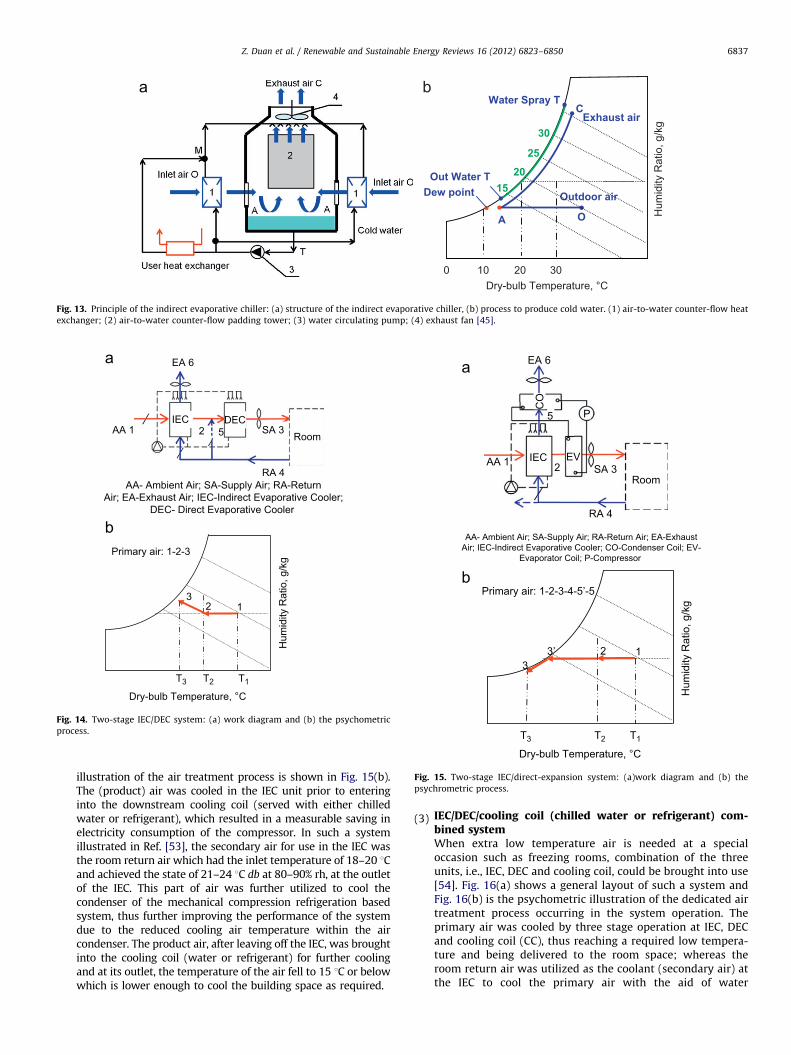
20
OA
3010
Water Spray T
Hum
idity
Rat
io, g
/kg
Dry-bulb Temperature, °C0
Outdoor air
Out Water T Dew point
C
30
25
2015
Exhaust air
Fig. 13. Principle of the indirect evaporative chiller: (a) structure of the indirect evaporative chiller, (b) process to produce cold water. (1) air-to-water counter-flow heat
exchanger; (2) air-to-water counter-flow padding tower; (3) water circulating pump; (4) exhaust fan [45].
T2
12
T1
3
T3
Primary air: 1-2-3
Hum
idity
Rat
io, g
/kg
Dry-bulb Temperature, °C
EA 6
AA 1 2 5 SA 3
RA 4
Room DECIEC
AA- Ambient Air; SA-Supply Air; RA-ReturnAir; EA-Exhaust Air; IEC-Indirect Evaporative Cooler;
DEC- Direct Evaporative Cooler
Fig. 14. Two-stage IEC/DEC system: (a) work diagram and (b) the psychometric
process.
Dry-bulb Temperature, °C
T2
12
T1
3’
T3
Primary air: 1-2-3-4-5’-5
Hum
idity
Rat
io, g
/kg
3
AA- Ambient Air; SA-Supply Air; RA-Return Air; EA-ExhaustAir; IEC-Indirect Evaporative Cooler; CO-Condenser Coil; EV-
Evaporator Coil; P-Compressor
AA 1
RA 4
SA 3Room
IEC EV2
5 P
CO
EA 6
Fig. 15. Two-stage IEC/direct-expansion system: (a)work diagram and (b) the
psychrometric process.
Z. Duan et al. / Renewable and Sustainable Energy Reviews 16 (2012) 6823–6850 6837
illustration of the air treatment process is shown in Fig. 15(b).The (product) air was cooled in the IEC unit prior to enteringinto the downstream cooling coil (served with either chilledwater or refrigerant), which resulted in a measurable saving inelectricity consumption of the compressor. In such a systemillustrated in Ref. [53], the secondary air for use in the IEC wasthe room return air which had the inlet temperature of 18–20 1Cand achieved the state of 21–24 1C db at 80–90% rh, at the outletof the IEC. This part of air was further utilized to cool thecondenser of the mechanical compression refrigeration basedsystem, thus further improving the performance of the systemdue to the reduced cooling air temperature within the aircondenser. The product air, after leaving off the IEC, was broughtinto the cooling coil (water or refrigerant) for further coolingand at its outlet, the temperature of the air fell to 15 1C or belowwhich is lower enough to cool the building space as required.
(3)
IEC/DEC/cooling coil (chilled water or refrigerant) com-bined systemWhen extra low temperature air is needed at a specialoccasion such as freezing rooms, combination of the threeunits, i.e., IEC, DEC and cooling coil, could be brought into use[54]. Fig. 16(a) shows a general layout of such a system andFig. 16(b) is the psychometric illustration of the dedicated airtreatment process occurring in the system operation. Theprimary air was cooled by three stage operation at IEC, DECand cooling coil (CC), thus reaching a required low tempera-ture and being delivered to the room space; whereas theroom return air was utilized as the coolant (secondary air) atthe IEC to cool the primary air with the aid of water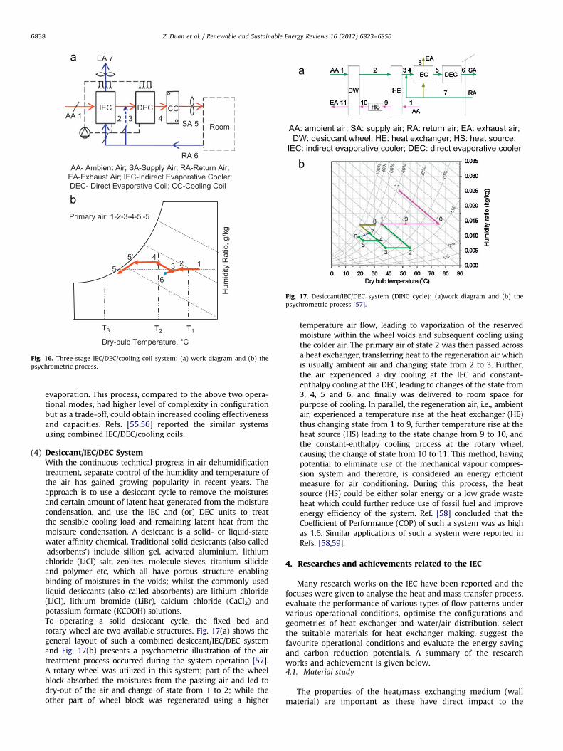
T2
12
T1
5’
T3
Primary air: 1-2-3-4-5’-5H
umid
ity R
atio
, g/k
g
3
6
45
Dry-bulb Temperature, °C
EA 7
SA 5
CCDECIECAA 1 2 3 4
RA 6
Room
AA- Ambient Air; SA-Supply Air; RA-Return Air;EA-Exhaust Air; IEC-Indirect Evaporative Cooler;DEC- Direct Evaporative Coil; CC-Cooling Coil
Fig. 16. Three-stage IEC/DEC/cooling coil system: (a) work diagram and (b) the
psychrometric process.
AA: ambient air; SA: supply air; RA: return air; EA: exhaust air;DW: desiccant wheel; HE: heat exchanger; HS: heat source;
IEC: indirect evaporative cooler; DEC: direct evaporative cooler
Fig. 17. Desiccant/IEC/DEC system (DINC cycle): (a)work diagram and (b) the
psychrometric process [57].
Z. Duan et al. / Renewable and Sustainable Energy Reviews 16 (2012) 6823–68506838
evaporation. This process, compared to the above two opera-tional modes, had higher level of complexity in configurationbut as a trade-off, could obtain increased cooling effectivenessand capacities. Refs. [55,56] reported the similar systemsusing combined IEC/DEC/cooling coils.
(4)
Desiccant/IEC/DEC SystemWith the continuous technical progress in air dehumidificationtreatment, separate control of the humidity and temperature ofthe air has gained growing popularity in recent years. Theapproach is to use a desiccant cycle to remove the moisturesand certain amount of latent heat generated from the moisturecondensation, and use the IEC and (or) DEC units to treatthe sensible cooling load and remaining latent heat from themoisture condensation. A desiccant is a solid- or liquid-statewater affinity chemical. Traditional solid desiccants (also called‘adsorbents’) include sillion gel, acivated aluminium, lithiumchloride (LiCl) salt, zeolites, molecule sieves, titanium silicideand polymer etc, which all have porous structure enablingbinding of moistures in the voids; whilst the commonly usedliquid desiccants (also called absorbents) are lithium chloride(LiCl), lithium bromide (LiBr), calcium chloride (CaCl2) andpotassium formate (KCOOH) solutions.To operating a solid desiccant cycle, the fixed bed androtary wheel are two available structures. Fig. 17(a) shows thegeneral layout of such a combined desiccant/IEC/DEC systemand Fig. 17(b) presents a psychometric illustration of the airtreatment process occurred during the system operation [57].A rotary wheel was utilized in this system; part of the wheelblock absorbed the moistures from the passing air and led todry-out of the air and change of state from 1 to 2; while theother part of wheel block was regenerated using a highertemperature air flow, leading to vaporization of the reservedmoisture within the wheel voids and subsequent cooling usingthe colder air. The primary air of state 2 was then passed acrossa heat exchanger, transferring heat to the regeneration air whichis usually ambient air and changing state from 2 to 3. Further,the air experienced a dry cooling at the IEC and constant-enthalpy cooling at the DEC, leading to changes of the state from3, 4, 5 and 6, and finally was delivered to room space forpurpose of cooling. In parallel, the regeneration air, i.e., ambientair, experienced a temperature rise at the heat exchanger (HE)thus changing state from 1 to 9, further temperature rise at theheat source (HS) leading to the state change from 9 to 10, andthe constant-enthalpy cooling process at the rotary wheel,causing the change of state from 10 to 11. This method, havingpotential to eliminate use of the mechanical vapour compres-sion system and therefore, is considered an energy efficientmeasure for air conditioning. During this process, the heatsource (HS) could be either solar energy or a low grade wasteheat which could further reduce use of fossil fuel and improveenergy efficiency of the system. Ref. [58] concluded that theCoefficient of Performance (COP) of such a system was as highas 1.6. Similar applications of such a system were reported inRefs. [58,59].
4. Researches and achievements related to the IEC
Many research works on the IEC have been reported and thefocuses were given to analyse the heat and mass transfer process,evaluate the performance of various types of flow patterns undervarious operational conditions, optimise the configurations andgeometries of heat exchanger and water/air distribution, selectthe suitable materials for heat exchanger making, suggest thefavourite operational conditions and evaluate the energy savingand carbon reduction potentials. A summary of the researchworks and achievement is given below.4.1. Material study
The properties of the heat/mass exchanging medium (wallmaterial) are important as these have direct impact to the
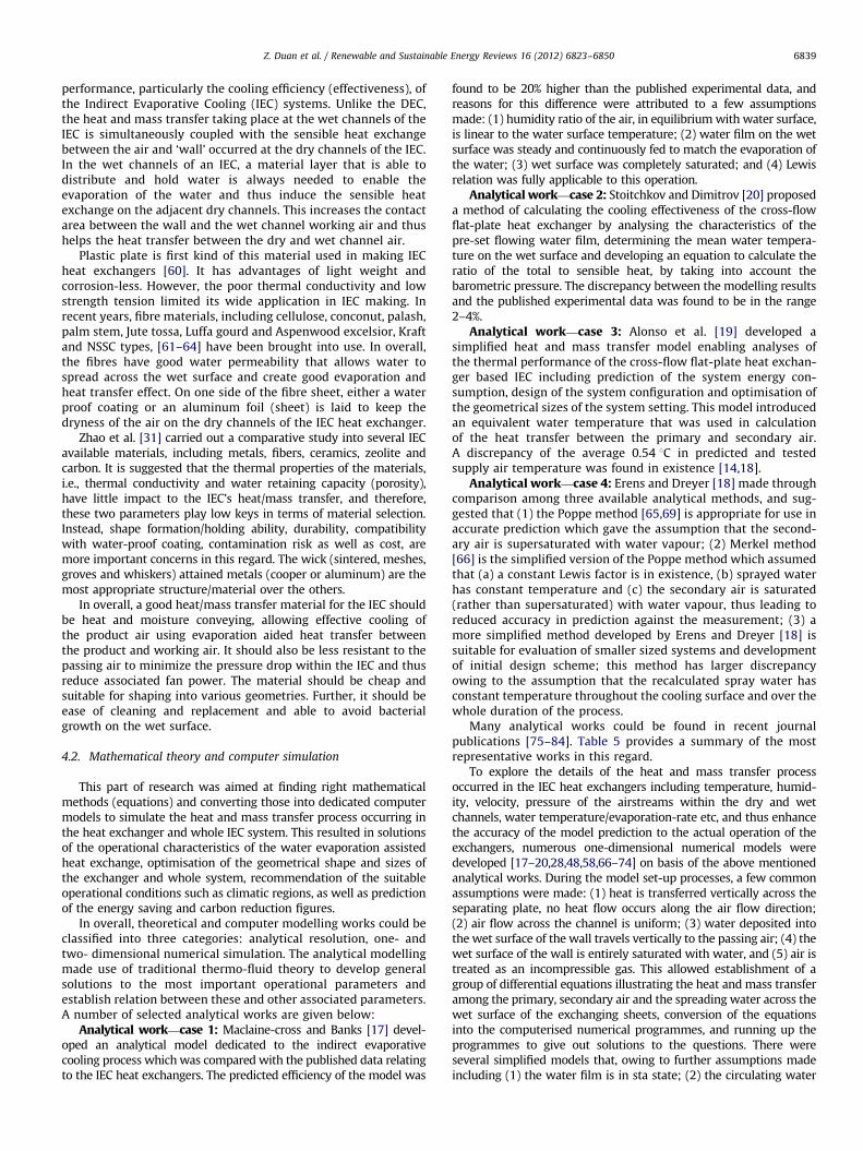
Z. Duan et al. / Renewable and Sustainable Energy Reviews 16 (2012) 6823–6850 6839
performance, particularly the cooling efficiency (effectiveness), ofthe Indirect Evaporative Cooling (IEC) systems. Unlike the DEC,the heat and mass transfer taking place at the wet channels of theIEC is simultaneously coupled with the sensible heat exchangebetween the air and ‘wall’ occurred at the dry channels of the IEC.In the wet channels of an IEC, a material layer that is able todistribute and hold water is always needed to enable theevaporation of the water and thus induce the sensible heatexchange on the adjacent dry channels. This increases the contactarea between the wall and the wet channel working air and thushelps the heat transfer between the dry and wet channel air.
Plastic plate is first kind of this material used in making IECheat exchangers [60]. It has advantages of light weight andcorrosion-less. However, the poor thermal conductivity and lowstrength tension limited its wide application in IEC making. Inrecent years, fibre materials, including cellulose, conconut, palash,palm stem, Jute tossa, Luffa gourd and Aspenwood excelsior, Kraftand NSSC types, [61–64] have been brought into use. In overall,the fibres have good water permeability that allows water tospread across the wet surface and create good evaporation andheat transfer effect. On one side of the fibre sheet, either a waterproof coating or an aluminum foil (sheet) is laid to keep thedryness of the air on the dry channels of the IEC heat exchanger.
Zhao et al. [31] carried out a comparative study into several IECavailable materials, including metals, fibers, ceramics, zeolite andcarbon. It is suggested that the thermal properties of the materials,i.e., thermal conductivity and water retaining capacity (porosity),have little impact to the IEC’s heat/mass transfer, and therefore,these two parameters play low keys in terms of material selection.Instead, shape formation/holding ability, durability, compatibilitywith water-proof coating, contamination risk as well as cost, aremore important concerns in this regard. The wick (sintered, meshes,groves and whiskers) attained metals (cooper or aluminum) are themost appropriate structure/material over the others.
In overall, a good heat/mass transfer material for the IEC shouldbe heat and moisture conveying, allowing effective cooling ofthe product air using evaporation aided heat transfer betweenthe product and working air. It should also be less resistant to thepassing air to minimize the pressure drop within the IEC and thusreduce associated fan power. The material should be cheap andsuitable for shaping into various geometries. Further, it should beease of cleaning and replacement and able to avoid bacterialgrowth on the wet surface.
4.2. Mathematical theory and computer simulation
This part of research was aimed at finding right mathematicalmethods (equations) and converting those into dedicated computermodels to simulate the heat and mass transfer process occurring inthe heat exchanger and whole IEC system. This resulted in solutionsof the operational characteristics of the water evaporation assistedheat exchange, optimisation of the geometrical shape and sizes ofthe exchanger and whole system, recommendation of the suitableoperational conditions such as climatic regions, as well as predictionof the energy saving and carbon reduction figures.
In overall, theoretical and computer modelling works could beclassified into three categories: analytical resolution, one- andtwo- dimensional numerical simulation. The analytical modellingmade use of traditional thermo-fluid theory to develop generalsolutions to the most important operational parameters andestablish relation between these and other associated parameters.A number of selected analytical works are given below:
Analytical work—case 1: Maclaine-cross and Banks [17] devel-oped an analytical model dedicated to the indirect evaporativecooling process which was compared with the published data relatingto the IEC heat exchangers. The predicted efficiency of the model was
found to be 20% higher than the published experimental data, andreasons for this difference were attributed to a few assumptionsmade: (1) humidity ratio of the air, in equilibrium with water surface,is linear to the water surface temperature; (2) water film on the wetsurface was steady and continuously fed to match the evaporation ofthe water; (3) wet surface was completely saturated; and (4) Lewisrelation was fully applicable to this operation.
Analytical work—case 2: Stoitchkov and Dimitrov [20] proposeda method of calculating the cooling effectiveness of the cross-flowflat-plate heat exchanger by analysing the characteristics of thepre-set flowing water film, determining the mean water tempera-ture on the wet surface and developing an equation to calculate theratio of the total to sensible heat, by taking into account thebarometric pressure. The discrepancy between the modelling resultsand the published experimental data was found to be in the range2–4%.
Analytical work—case 3: Alonso et al. [19] developed asimplified heat and mass transfer model enabling analyses ofthe thermal performance of the cross-flow flat-plate heat exchan-ger based IEC including prediction of the system energy con-sumption, design of the system configuration and optimisation ofthe geometrical sizes of the system setting. This model introducedan equivalent water temperature that was used in calculationof the heat transfer between the primary and secondary air.A discrepancy of the average 0.54 1C in predicted and testedsupply air temperature was found in existence [14,18].
Analytical work—case 4: Erens and Dreyer [18] made throughcomparison among three available analytical methods, and sug-gested that (1) the Poppe method [65,69] is appropriate for use inaccurate prediction which gave the assumption that the second-ary air is supersaturated with water vapour; (2) Merkel method[66] is the simplified version of the Poppe method which assumedthat (a) a constant Lewis factor is in existence, (b) sprayed waterhas constant temperature and (c) the secondary air is saturated(rather than supersaturated) with water vapour, thus leading toreduced accuracy in prediction against the measurement; (3) amore simplified method developed by Erens and Dreyer [18] issuitable for evaluation of smaller sized systems and developmentof initial design scheme; this method has larger discrepancyowing to the assumption that the recalculated spray water hasconstant temperature throughout the cooling surface and over thewhole duration of the process.
Many analytical works could be found in recent journalpublications [75–84]. Table 5 provides a summary of the mostrepresentative works in this regard.
To explore the details of the heat and mass transfer processoccurred in the IEC heat exchangers including temperature, humid-ity, velocity, pressure of the airstreams within the dry and wetchannels, water temperature/evaporation-rate etc, and thus enhancethe accuracy of the model prediction to the actual operation of theexchangers, numerous one-dimensional numerical models weredeveloped [17–20,28,48,58,66–74] on basis of the above mentionedanalytical works. During the model set-up processes, a few commonassumptions were made: (1) heat is transferred vertically across theseparating plate, no heat flow occurs along the air flow direction;(2) air flow across the channel is uniform; (3) water deposited intothe wet surface of the wall travels vertically to the passing air; (4) thewet surface of the wall is entirely saturated with water, and (5) air istreated as an incompressible gas. This allowed establishment of agroup of differential equations illustrating the heat and mass transferamong the primary, secondary air and the spreading water across thewet surface of the exchanging sheets, conversion of the equationsinto the computerised numerical programmes, and running up theprogrammes to give out solutions to the questions. There wereseveral simplified models that, owing to further assumptions madeincluding (1) the water film is in sta state; (2) the circulating water
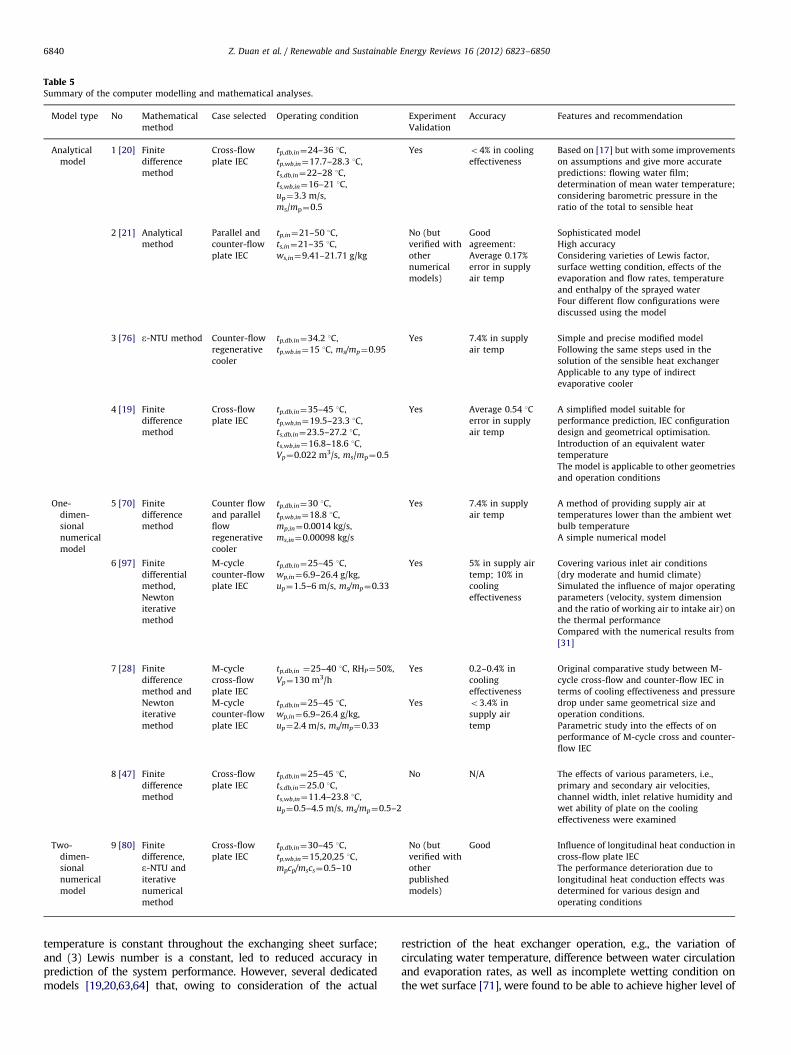
Table 5Summary of the computer modelling and mathematical analyses.
Model type No Mathematical
method
Case selected Operating condition Experiment
Validation
Accuracy Features and recommendation
Analytical
model
1 [20] Finite
difference
method
Cross-flow
plate IEC
tp,db,in¼24–36 1C,
tp,wb,in¼17.7–28.3 1C,
ts,db,in¼22–28 1C,
ts,wb,in¼16–21 1C,
up¼3.3 m/s,
ms/mp¼0.5
Yes o4% in cooling
effectiveness
Based on [17] but with some improvements
on assumptions and give more accurate
predictions: flowing water film;
determination of mean water temperature;
considering barometric pressure in the
ratio of the total to sensible heat
2 [21] Analytical
method
Parallel and
counter-flow
plate IEC
tp,in¼21–50 1C,
ts,in¼21–35 1C,
ws,in¼9.41–21.71 g/kg
No (but
verified with
other
numerical
models)
Good
agreement:
Average 0.17%
error in supply
air temp
Sophisticated model
High accuracy
Considering varieties of Lewis factor,
surface wetting condition, effects of the
evaporation and flow rates, temperature
and enthalpy of the sprayed water
Four different flow configurations were
discussed using the model
3 [76] e-NTU method Counter-flow
regenerative
cooler
tp,db.in¼34.2 1C,
tp,wb.in¼15 1C, ms/mp¼0.95
Yes 7.4% in supply
air temp
Simple and precise modified model
Following the same steps used in the
solution of the sensible heat exchanger
Applicable to any type of indirect
evaporative cooler
4 [19] Finite
difference
method
Cross-flow
plate IEC
tp,db,in¼35–45 1C,
tp,wb,in¼19.5–23.3 1C,
ts,db,in¼23.5–27.2 1C,
ts,wb,in¼16.8–18.6 1C,
Vp¼0.022 m3/s, ms/mp¼0.5
Yes Average 0.54 1C
error in supply
air temp
A simplified model suitable for
performance prediction, IEC configuration
design and geometrical optimisation.
Introduction of an equivalent water
temperature
The model is applicable to other geometries
and operation conditions
One-
dimen-
sional
numerical
model
5 [70] Finite
difference
method
Counter flow
and parallel
flow
regenerative
cooler
tp,db,in¼30 1C,
tp,wb,in¼18.8 1C,
mp,in¼0.0014 kg/s,
ms,in¼0.00098 kg/s
Yes 7.4% in supply
air temp
A method of providing supply air at
temperatures lower than the ambient wet
bulb temperature
A simple numerical model
6 [97] Finite
differential
method,
Newton
iterative
method
M-cycle
counter-flow
plate IEC
tp,db,in¼25–45 1C,
wp,in¼6.9–26.4 g/kg,
up¼1.5–6 m/s, ms/mp¼0.33
Yes 5% in supply air
temp; 10% in
cooling
effectiveness
Covering various inlet air conditions
(dry moderate and humid climate)
Simulated the influence of major operating
parameters (velocity, system dimension
and the ratio of working air to intake air) on
the thermal performance
Compared with the numerical results from
[31]
7 [28] Finite
difference
method and
Newton
iterative
method
M-cycle
cross-flow
plate IEC
tp,db,in ¼25–40 1C, RHP¼50%,
Vp¼130 m3/h
Yes 0.2–0.4% in
cooling
effectiveness
Original comparative study between M-
cycle cross-flow and counter-flow IEC in
terms of cooling effectiveness and pressure
drop under same geometrical size and
operation conditions.
Parametric study into the effects of on
performance of M-cycle cross and counter-
flow IEC
M-cycle
counter-flow
plate IEC
tp,db,in¼25–45 1C,
wp,in¼6.9–26.4 g/kg,
up¼2.4 m/s, ms/mp¼0.33
Yes o3.4% in
supply air
temp
8 [47] Finite
difference
method
Cross-flow
plate IEC
tp,db,in¼25–45 1C,
ts,db,in¼25.0 1C,
ts,wb,in¼11.4–23.8 1C,
up¼0.5–4.5 m/s, ms/mp¼0.5–2
No N/A The effects of various parameters, i.e.,
primary and secondary air velocities,
channel width, inlet relative humidity and
wet ability of plate on the cooling
effectiveness were examined
Two-
dimen-
sional
numerical
model
9 [80] Finite
difference,
e-NTU and
iterative
numerical
method
Cross-flow
plate IEC
tp,db,in¼30–45 1C,
tp,wb,in¼15,20,25 1C,
mpcp/mscs¼0.5–10
No (but
verified with
other
published
models)
Good Influence of longitudinal heat conduction in
cross-flow plate IEC
The performance deterioration due to
longitudinal heat conduction effects was
determined for various design and
operating conditions
Z. Duan et al. / Renewable and Sustainable Energy Reviews 16 (2012) 6823–68506840
temperature is constant throughout the exchanging sheet surface;and (3) Lewis number is a constant, led to reduced accuracy inprediction of the system performance. However, several dedicatedmodels [19,20,63,64] that, owing to consideration of the actual
restriction of the heat exchanger operation, e.g., the variation ofcirculating water temperature, difference between water circulationand evaporation rates, as well as incomplete wetting condition onthe wet surface [71], were found to be able to achieve higher level of
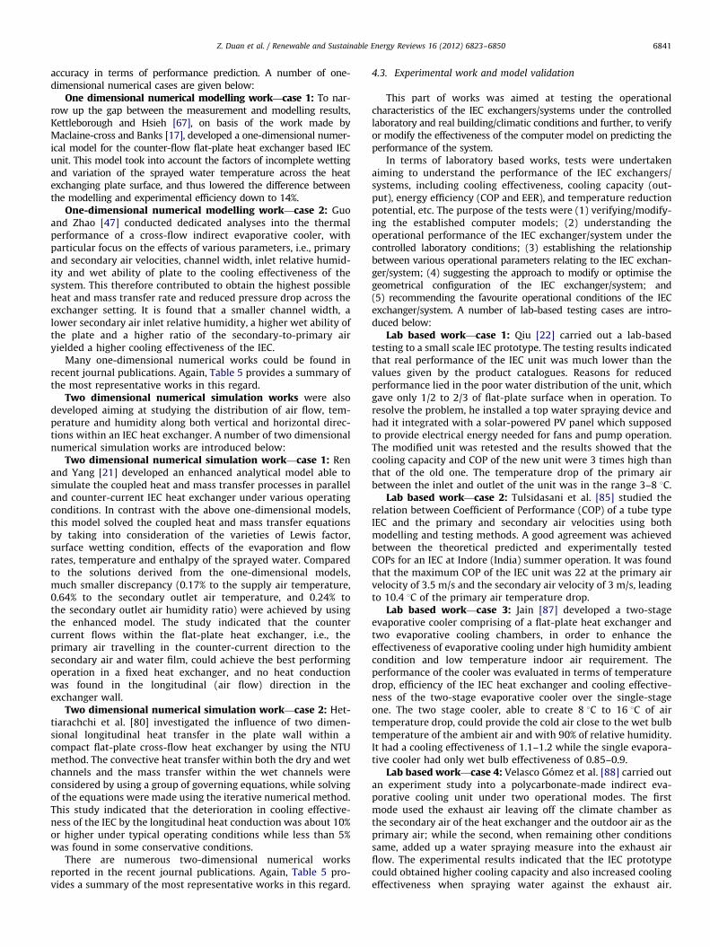
Z. Duan et al. / Renewable and Sustainable Energy Reviews 16 (2012) 6823–6850 6841
accuracy in terms of performance prediction. A number of one-dimensional numerical cases are given below:
One dimensional numerical modelling work—case 1: To nar-row up the gap between the measurement and modelling results,Kettleborough and Hsieh [67], on basis of the work made byMaclaine-cross and Banks [17], developed a one-dimensional numer-ical model for the counter-flow flat-plate heat exchanger based IECunit. This model took into account the factors of incomplete wettingand variation of the sprayed water temperature across the heatexchanging plate surface, and thus lowered the difference betweenthe modelling and experimental efficiency down to 14%.
One-dimensional numerical modelling work—case 2: Guoand Zhao [47] conducted dedicated analyses into the thermalperformance of a cross-flow indirect evaporative cooler, withparticular focus on the effects of various parameters, i.e., primaryand secondary air velocities, channel width, inlet relative humid-ity and wet ability of plate to the cooling effectiveness of thesystem. This therefore contributed to obtain the highest possibleheat and mass transfer rate and reduced pressure drop across theexchanger setting. It is found that a smaller channel width, alower secondary air inlet relative humidity, a higher wet ability ofthe plate and a higher ratio of the secondary-to-primary airyielded a higher cooling effectiveness of the IEC.
Many one-dimensional numerical works could be found inrecent journal publications. Again, Table 5 provides a summary ofthe most representative works in this regard.
Two dimensional numerical simulation works were alsodeveloped aiming at studying the distribution of air flow, tem-perature and humidity along both vertical and horizontal direc-tions within an IEC heat exchanger. A number of two dimensionalnumerical simulation works are introduced below:
Two dimensional numerical simulation work—case 1: Renand Yang [21] developed an enhanced analytical model able tosimulate the coupled heat and mass transfer processes in paralleland counter-current IEC heat exchanger under various operatingconditions. In contrast with the above one-dimensional models,this model solved the coupled heat and mass transfer equationsby taking into consideration of the varieties of Lewis factor,surface wetting condition, effects of the evaporation and flowrates, temperature and enthalpy of the sprayed water. Comparedto the solutions derived from the one-dimensional models,much smaller discrepancy (0.17% to the supply air temperature,0.64% to the secondary outlet air temperature, and 0.24% tothe secondary outlet air humidity ratio) were achieved by usingthe enhanced model. The study indicated that the countercurrent flows within the flat-plate heat exchanger, i.e., theprimary air travelling in the counter-current direction to thesecondary air and water film, could achieve the best performingoperation in a fixed heat exchanger, and no heat conductionwas found in the longitudinal (air flow) direction in theexchanger wall.
Two dimensional numerical simulation work—case 2: Het-tiarachchi et al. [80] investigated the influence of two dimen-sional longitudinal heat transfer in the plate wall within acompact flat-plate cross-flow heat exchanger by using the NTUmethod. The convective heat transfer within both the dry and wetchannels and the mass transfer within the wet channels wereconsidered by using a group of governing equations, while solvingof the equations were made using the iterative numerical method.This study indicated that the deterioration in cooling effective-ness of the IEC by the longitudinal heat conduction was about 10%or higher under typical operating conditions while less than 5%was found in some conservative conditions.
There are numerous two-dimensional numerical worksreported in the recent journal publications. Again, Table 5 pro-vides a summary of the most representative works in this regard.
4.3. Experimental work and model validation
This part of works was aimed at testing the operationalcharacteristics of the IEC exchangers/systems under the controlledlaboratory and real building/climatic conditions and further, to verifyor modify the effectiveness of the computer model on predicting theperformance of the system.
In terms of laboratory based works, tests were undertakenaiming to understand the performance of the IEC exchangers/systems, including cooling effectiveness, cooling capacity (out-put), energy efficiency (COP and EER), and temperature reductionpotential, etc. The purpose of the tests were (1) verifying/modify-ing the established computer models; (2) understanding theoperational performance of the IEC exchanger/system under thecontrolled laboratory conditions; (3) establishing the relationshipbetween various operational parameters relating to the IEC exchan-ger/system; (4) suggesting the approach to modify or optimise thegeometrical configuration of the IEC exchanger/system; and(5) recommending the favourite operational conditions of the IECexchanger/system. A number of lab-based testing cases are intro-duced below:
Lab based work—case 1: Qiu [22] carried out a lab-basedtesting to a small scale IEC prototype. The testing results indicatedthat real performance of the IEC unit was much lower than thevalues given by the product catalogues. Reasons for reducedperformance lied in the poor water distribution of the unit, whichgave only 1/2 to 2/3 of flat-plate surface when in operation. Toresolve the problem, he installed a top water spraying device andhad it integrated with a solar-powered PV panel which supposedto provide electrical energy needed for fans and pump operation.The modified unit was retested and the results showed that thecooling capacity and COP of the new unit were 3 times high thanthat of the old one. The temperature drop of the primary airbetween the inlet and outlet of the unit was in the range 3–8 1C.
Lab based work—case 2: Tulsidasani et al. [85] studied therelation between Coefficient of Performance (COP) of a tube typeIEC and the primary and secondary air velocities using bothmodelling and testing methods. A good agreement was achievedbetween the theoretical predicted and experimentally testedCOPs for an IEC at Indore (India) summer operation. It was foundthat the maximum COP of the IEC unit was 22 at the primary airvelocity of 3.5 m/s and the secondary air velocity of 3 m/s, leadingto 10.4 1C of the primary air temperature drop.
Lab based work—case 3: Jain [87] developed a two-stageevaporative cooler comprising of a flat-plate heat exchanger andtwo evaporative cooling chambers, in order to enhance theeffectiveness of evaporative cooling under high humidity ambientcondition and low temperature indoor air requirement. Theperformance of the cooler was evaluated in terms of temperaturedrop, efficiency of the IEC heat exchanger and cooling effective-ness of the two-stage evaporative cooler over the single-stageone. The two stage cooler, able to create 8 1C to 16 1C of airtemperature drop, could provide the cold air close to the wet bulbtemperature of the ambient air and with 90% of relative humidity.It had a cooling effectiveness of 1.1–1.2 while the single evapora-tive cooler had only wet bulb effectiveness of 0.85–0.9.
Lab based work—case 4: Velasco Gomez et al. [88] carried outan experiment study into a polycarbonate-made indirect eva-porative cooling unit under two operational modes. The firstmode used the exhaust air leaving off the climate chamber asthe secondary air of the heat exchanger and the outdoor air as theprimary air; while the second, when remaining other conditionssame, added up a water spraying measure into the exhaust airflow. The experimental results indicated that the IEC prototypecould obtained higher cooling capacity and also increased coolingeffectiveness when spraying water against the exhaust air.
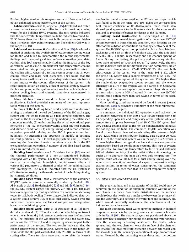
Z. Duan et al. / Renewable and Sustainable Energy Reviews 16 (2012) 6823–68506842
Further, higher outdoor air temperature or air flow rate helpedobtain enhanced cooling performance of the system.
Lab based work—case 5: Jiang et al. [45] developed and testeda novel indirect evaporative chiller for use in providing coolingwater for the building HVAC systems. The test results indicatedthat the outlet water temperature could be reduced to around 14–20 1C, lower than the inlet air wet bulb temperature and higherthan its relevant dew point temperature. The chiller’s COP was inthe range 0.4–0.8.
Lab based work—case 6: Costelloe and Finn [89] developed amethod of analysing the availability of evaporative cooling waterfor Dublin and Milan by incorporating the recent experimentalfindings and meteorological test reference weather year data.Further, they [90] experimentally studied the impacts of the keyoperational variables (e.g., ambient wet bulb temperature, coolingtower air-flow rate, primary and secondary water-flow rate) tothe cooling effectiveness of a testing system comprising an opencooling tower and plate heat exchanger. They found that thecooling tower air-flow rate and secondary water-flow rate have astrong impact to the cooling effectiveness of the system; thisresult helped obtain an energy efficient control strategy towardsthe fan and pump in the system which would enable adaption tovarious cooling loads and climatic conditions encountered inpractical operation.
Many lab based works could be found in recent journalpublications. Table 6 provided a summary of the most represen-tative works in this regard.
In terms of the building based works, tests were undertakenaiming to understand the real performance of the IEC exchanger/system and the whole building at a real climatic condition. Thepurpose of the tests were (1) verifying/modifying the establishedcomputer models; (2) understanding the actual operational per-formance of the IEC exchanger/systems under the real buildingand climatic conditions; (3) energy saving and carbon emissionreduction potential relating to the IEC implementation intobuildings; (4) suggesting the approach to modify or optimisethe configuration of the IEC exchanger/system; and (5) recom-mending the favourite climatic conditions adaptable to the IECexchanger/system operation. A number of building-based testingcases are introduced below:
Building based work—case 1: Tulsidasani et al. [85] studiedthe thermal performance of a non-air-conditioned buildingequipped with an IEC system. For three different climatic condi-tions at India (dry/hot, humid/hot, humid/warm), effects ofvarious IEC parameters to thermal comfort of the building spacewas investigated. The results indicated that the IEC system iseffective in improving the thermal comfort of the buildings in dry/hot climatic condition.
Building based work—case 2: Performance of the combinedIEC/DEC systems were experimentally studied by Scofield [86],Al-Marafie et al. [3], Heidarinejad G [23] and Jain [87]. In Ref. [86],the IEC/DEC system passed the primary air into a IEC flat-plateheat exchanger for dry cooling and then to a conventional coolingtower for adiabatic cooling. The testing results indicated that sucha system could achieve 30% of fossil fuel energy saving over thesame sized conventional mechanical compression refrigerationbased air conditioning system.
Building based work—case 3: El-Dessouky et al. [3] intro-duced a combined IEC/DEC unit installed on a building in Kuwaitwhere the ambient dry bulb temperature in summer is often above45 1C. The thickness of the wet packing (for DEC) and water flowrate across the DEC were found to impose significant impact to theperformance of the system. The test results indicated that thecooling effectiveness of the IEC/DEC system was in the range 90–105% while the IEC part contributed only 20–40% in terms of itscooling effect. These test data were used to correlate the Nusselt
number for the airstreams outside the IEC heat exchanger, whichwas found to be in the range 150–450, giving the correspondingheat transfer coefficient of 0.1–0.4 kW/m2 k. These results alsoshowed good agreement to the literature data for the same condi-tion and so provided references for design of the IEC units.
Building based work—case 4: Heidarinejad et al. [23]reported an experimental investigation of a two-stage IEC/DECsystem operated in Iran’s climatic condition, with focusing on theeffect of the outdoor air conditions on cooling effectiveness of thesystem. The IEC/DEC system comprised of a plastic flat-plate heatexchanger and a 15 cm thick of cellulose pad, with the unit sizesof 500�500�400 mm, respectively and the channel spacing of7 mm. During the testing, the primary and secondary air flowrates were adjusted to 1700 and 850 m3/h, respectively. The testresults indicated that under different inlet air parameters, (inletdry/wet-bulb temperature: 27–49 1C/15–33 1C), the wet bulbeffectiveness of the system was in the range 108–111%, whilethe single IEC system had a cooling effectiveness of 55–61%. Theaverage water consumption of the system was 55% higher thanthe single direct evaporative cooling system, and the energyefficiency (or COP) of the system was in a range 8–9. Comparedto the typical mechanical vapour compression refrigeration basedsystems which have a COP of around 3, the two-stage IEC/DECsystem could obtain more than 60% saving in terms of the fossilfuel energy consumption.
Many building based works could be found in recent journalapplication. Table 6 provides a summary of the most representa-tive works in this regard.
In summary, the individual IEC operation could achieve thewet bulb effectiveness as high as 0.4–0.9; its COP varied from 5 to15 depending upon size and complexity of the system; while airtemperature drop was between 5 and 10 1C. The IEC system hadvery positive cooling effect to the non air-conditioned buildings atthe hot regions like India. The combined IEC/DEC operation wasfound to be able to achieve enhanced cooling effectiveness as highas 90–120%, while the contribution from IEC part is about 20–60%.The COP of the combined system was in the range 8–22, which is3 times higher than the typical mechanical vapour compressionrefrigeration based air conditioning systems. This type of systemhad potential to lower air temperature by 8–16 1C and obtained90% of relative humidity of at the outlet of the unit, allowing theoutlet air to approach the inlet air’s wet-bulb temperature. Thesystem could achieve 30–60% fossil fuel energy saving over thesame sized conventional mechanical vapour compression refrig-eration system. In terms of water consumption, the combinedsystem is 50–60% higher than that in a direct evaporative coolingsystem.
4.4. Effect of the water distribution
The predicted heat and mass transfer of the IEC could only beachieved on the condition of obtaining complete wetting of thewet channels surfaces. Poor water distribution on the surfaceswould reduce the heat/mass transfer rate between the primary airand the water film, and between the water film and secondary air,which would eventually undermine the effectiveness of theindirect evaporative cooler.
The most commonly used water spraying method in indirectevaporative coolers is by sparking nozzles, as shown schemati-cally in Fig. 18 [91]. The nozzle sprayers are positioned above thecross-flow heat exchanger, sprinkling the atomized water drizzlesover the upcoming secondary airstreams. The water, whensprayed into the wet channels, wets the surface of the channelsand enables the heat/moisture exchange between the water andthe secondary air, thus causing evaporation of large proportion ofwater. Meanwhile, the remaining water drops into the bottom
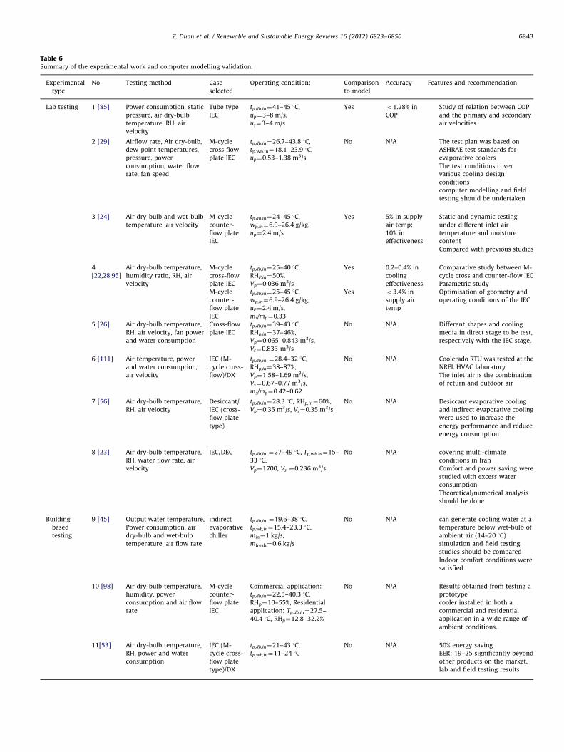
Table 6Summary of the experimental work and computer modelling validation.
Experimental
type
No Testing method Case
selected
Operating condition: Comparison
to model
Accuracy Features and recommendation
Lab testing 1 [85] Power consumption, static
pressure, air dry-bulb
temperature, RH, air
velocity
Tube type
IEC
tp,db,in¼41–45 1C,
up¼3–8 m/s,
us¼3–4 m/s
Yes o1.28% in
COP
Study of relation between COP
and the primary and secondary
air velocities
2 [29] Airflow rate, Air dry-bulb,
dew-point temperatures,
pressure, power
consumption, water flow
rate, fan speed
M-cycle
cross flow
plate IEC
tp,db,in¼26.7–43.8 1C,
tp,wb,in¼18.1–23.9 1C,
up¼0.53–1.38 m3/s
No N/A The test plan was based on
ASHRAE test standards for
evaporative coolers
The test conditions cover
various cooling design
conditions
computer modelling and field
testing should be undertaken
3 [24] Air dry-bulb and wet-bulb
temperature, air velocity
M-cycle
counter-
flow plate
IEC
tp,db,in¼24–45 1C,
wp,in¼6.9–26.4 g/kg,
up¼2.4 m/s
Yes 5% in supply
air temp;
10% in
effectiveness
Static and dynamic testing
under different inlet air
temperature and moisture
content
Compared with previous studies
4
[22,28,95]
Air dry-bulb temperature,
humidity ratio, RH, air
velocity
M-cycle
cross-flow
plate IEC
tp,db,in¼25–40 1C,
RHP,in¼50%,
Vp¼0.036 m3/s
Yes 0.2–0.4% in
cooling
effectiveness
Comparative study between M-
cycle cross and counter-flow IEC
Parametric study
Optimisation of geometry and
operating conditions of the IEC
M-cycle
counter-
flow plate
IEC
tp,db,in¼25–45 1C,
wp,in¼6.9–26.4 g/kg,
uP¼2.4 m/s,
ms/mp¼0.33
Yes o3.4% in
supply air
temp
5 [26] Air dry-bulb temperature,
RH, air velocity, fan power
and water consumption
Cross-flow
plate IEC
tp,db,in¼39–43 1C,
RHp,in¼37–46%,
Vp¼0.065–0.843 m3/s,
Vs¼0.833 m3/s
No N/A Different shapes and cooling
media in direct stage to be test,
respectively with the IEC stage.
6 [111] Air temperature, power
and water consumption,
air velocity
IEC (M-
cycle cross-
flow)/DX
tp,db,in ¼28.4–32 1C,
RHp,in¼38–87%,
Vp¼1.58–1.69 m3/s,
Vs¼0.67–0.77 m3/s,
ms/mp¼0.42–0.62
No N/A Coolerado RTU was tested at the
NREL HVAC laboratory
The inlet air is the combination
of return and outdoor air
7 [56] Air dry-bulb temperature,
RH, air velocity
Desiccant/
IEC (cross-
flow plate
type)
tp,db.in¼28.3 1C, RHp,in¼60%,
Vp¼0.35 m3/s, Vs¼0.35 m3/s
No N/A Desiccant evaporative cooling
and indirect evaporative cooling
were used to increase the
energy performance and reduce
energy consumption
8 [23] Air dry-bulb temperature,
RH, water flow rate, air
velocity
IEC/DEC tp,db,in ¼27–49 1C, Tp,wb.in¼15–
33 1C,
Vp¼1700, Vs ¼0.236 m3/s
No N/A covering multi-climate
conditions in Iran
Comfort and power saving were
studied with excess water
consumption
Theoretical/numerical analysis
should be done
Building
based
testing
9 [45] Output water temperature,
Power consumption, air
dry-bulb and wet-bulb
temperature, air flow rate
indirect
evaporative
chiller
tp,db,in ¼19.6–38 1C,
tp,wb,in¼15.4–23.3 1C,
min¼1 kg/s,
mfresh¼0.6 kg/s
No N/A can generate cooling water at a
temperature below wet-bulb of
ambient air (14–20 1C)
simulation and field testing
studies should be compared
Indoor comfort conditions were
satisfied
10 [98] Air dry-bulb temperature,
humidity, power
consumption and air flow
rate
M-cycle
counter-
flow plate
IEC
Commercial application:
tp,db,in¼22.5–40.3 1C,
RHp¼10–55%, Residential
application: Tp,db,in¼27.5–
40.4 1C, RHp¼12.8–32.2%
No N/A Results obtained from testing a
prototype
cooler installed in both a
commercial and residential
application in a wide range of
ambient conditions.
11[53] Air dry-bulb temperature,
RH, power and water
consumption
IEC (M-
cycle cross-
flow plate
type)/DX
tp,db,in¼21–43 1C,
tp,wb,in¼11–24 1C
No N/A 50% energy saving
EER: 19–25 significantly beyond
other products on the market.
lab and field testing results
Z. Duan et al. / Renewable and Sustainable Energy Reviews 16 (2012) 6823–6850 6843
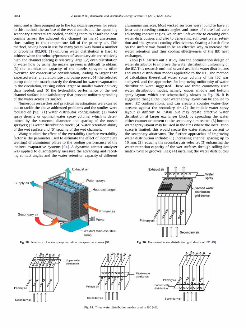
Z. Duan et al. / Renewable and Sustainable Energy Reviews 16 (2012) 6823–68506844
sump and is then pumped up to the top nozzle sprayers for reuse.In this method, the surface of the wet channels and the upcomingsecondary airstream are cooled, enabling them to absorb the heatcoming across the adjacent dry channel (primary) airstreams,thus leading to the temperature fall of the primary air. Thismethod, having been in use for many years, was found a numberof problems [92,93]: (1) uniform water distribution is hard toachieve when the velocity/pressure of secondary air are relativelyhigh and channel spacing is relatively large; (2) even distributionof water flow by using the nozzle sprayers is difficult to obtain;(3) the atomization capacity of the nozzle sprayers is oftenoversized for conservative consideration, leading to larger thanexpected water circulation rate and pump power; (4) the selectedpump could not match exactly the demand for water evaporationin the circulation, causing either larger or smaller water deliverythan needed; and (5) the hydrophilic performance of the wetchannel surface is unsatisfactory that prevent uniform spreadingof the water across its surface.
Numerous researches and practical investigations were carriedout to tackle the above addressed problems and the studies werefocused on [92]: (1) water distributor configuration; (2) waterspray density or optimal water spray volume, which is deter-mined by the structure, diameter and spacing of the nozzlesprayers; (3) water distribution mode; (4) water retention abilityof the wet surface and (5) spacing of the wet channels.
Wang studied the effect of the wettability (surface wettabilityfactor is the parameter used to estimate the effect of incompletewetting) of aluminium plates to the cooling performance of theindirect evaporative systems [94]. A dynamic contact analyserwas applied to quantitatively measure the advancing and reced-ing contact angles and the water-retention capacity of different
Exhaust air
Water sprays
Heat exchanger
Primary air
Pump
Welded stainless steelsump
Supply air
Secondary air
Fig. 18. Schematic of water sprays in indirect evaporative coolers [91].
Fig. 19. Three water distributio
aluminium surfaces. Most wicked surfaces were found to have atleast zero receding contact angles and some of those had zeroadvancing contact angles, which are unfavourite to creating evenwater distribution, and also to generating sufficient water reten-tion and the system’s cooling effectiveness. Coating a harsh fibreon the surface was found to be an effective way to increase thewater retention and thus cooling effectiveness of the IEC heatexchanger.
Zhou [93] carried out a study into the optimisation design ofwater distributor to improve the water distribution uniformity ofthe IEC. This research outlined several available water distributorsand water distribution modes applicable to the IEC. The methodof calculating theoretical water spray volume of the IEC wasanalyzed, and the approaches for improving uniformity of waterdistribution were suggested. There are three commonly usedwater distribution modes, namely, upper, middle and bottomspray layout, which are schematically shown in Fig. 19. It issuggested that (1) the upper water spray layout can be applied tomost IEC configurations, and can create a counter water-flowstreams against the secondary air. (2) the middle water spraylayout is difficult to install but may create effective waterdistribution at larger exchanger block by spreading the watereither counter or current to the secondary airstreams; (3) bottomwater spray layout may be used in the sites where the installationspace is limited; this would create the water streams current tothe secondary airstreams. The further approaches of improvingwater distribution include: (1) increasing channel spacing up to10 mm; (2) reducing the secondary air velocity; (3) enhancing thewater retention capacity of the wet surfaces through rolling dotmatrix twill or grooves lines; (4) installing the water distributors
n modes used in IEC [49].
Fig. 20. The second water distribution grid device of IEC [49].
Z. Duan et al. / Renewable and Sustainable Energy Reviews 16 (2012) 6823–6850 6845
to appropriate position to create the right water streams; and (5)adding up a second water distribution grid beneath the first watersprays, as shown in Fig. 20.
In recent years, a new type of water distribution method wasapplied to the IEC unit [95] and this used the regularly perforated,small sized tubes that were laid on the slots of the wet channelsto discharge the water streams to the wet surfaces of the channels.The water streams, when flowing downward along the channelwalls, spread across the walls along the horizontal direction andowing to the permeability effect of the wet surfaces and small flowrate of the water streams, the water quickly spread along thehorizontal direction and thus formed uniform distribution of thewater across the walls. In this case, the flow rate of the water was 2–3 times of the water evaporation rate.
4.5. M-cycle IEC systems and associated performance measures
A new M-cycle IEC system [34] was developed to enableobtaining enhanced cooling effectiveness, reduced supply airtemperature and increased per unit volume cooling capacitycompared to conventional IEC systems. Its system configurations,associated theories and computer models, experimental testingand performance evaluation measures were broadly studied inrecent years [11,29–32,96,97].
Pacific Gas and Electric Company carried out a lab-based testingfor the Coolerado Cross-Flow M-Cycle IEC unit [29]. Effect of theinlet air dry/wet bulb temperatures, outlet back-pressure, fan speed,airflow rate to performance of the unit including cooling effective-ness, cooling capacity, power consumption, cooling capacity, energyefficiency and water evaporation rate were broadly investigatedusing the experimental method. The testing results indicated thatthe wet-bulb effectiveness of unit varied from 81% to 91% over thefull range of testing conditions, which is 15–30% higher than that ofthe normal IEC systems. Under all sets of testing conditions, the unitcould provide a supply air of 18.9–25.6 1C in dry-bulb and 30–80% inrelative humidity. The average energy efficiency (COP) of unit wasover 8.8, leading to 40–80% reduction in fossil fuel energy con-sumption relative to the normal IEC system.
Zhao et al. developed a novel counter-flow IEC module andconducted various sets of investigation into its performance usingboth theoretical and experimental methods [12,28,30–32].In terms of computer simulation, the equations governing theheat and mass transfer between air, water and exchanging platewithin the dry and wet channels of the IEC unit was coupled andsolved using the finite-element differential approach. The NewtonIterative Method was applied to the simulation process. Themodel predicted that the wet-bulb effectiveness of the coolercould be as high as 130% under the UK’s summer outdoor airdesign condition (28 1C db and 20 1C wb) if wet surface of theexchange plate is completely saturated. It also indicated thatchannel sizes, air velocities and secondary-to-primary air ratioshad important impact to the cooling effectiveness and energyefficiency of the cooler, while the feed water temperature hadless. Several geometrical and operational parameters were sug-gested to help design of the heat exchanger; these include: (1)channel spacing gap should be less than 6 mm; (2) length of thechannels should be longer than 1 m or 200 time of channelspacing gap; (3) secondary-to-primary air ratio should be around0.4; and (4) the intake air velocity should be set to 0.3–0.5 m/s.
Riangvilaikul and Kumar [97] presented a similar numerical studyof a counter-flow dew point indirect evaporative cooler. The studydeveloped a numerical model to simulate the heat and mass transferprocess occurred in the dew point cooler. The governing equationswere solved by employing finite differential approach and Newtoniterative method to obtain temperature and humidity values of theair across the whole channel space. The modelling results were
validated using the experimental data [24] under various inlet airconditions (typically covering dry, moderate and humid climates)and for different intake air velocities (1.5–6 m/s). Reasonable agree-ment was achieved between the numerical and experimental results,giving 5–10% of deviation in terms of the outlet air temperature andeffectiveness, respectively. The study also showed that the predicteddew point effectiveness varied significantly from 65 to 86% when theinlet air humidity changed from 6.9 g/kg to 26.4 g/kg at the constantinlet temperature of 35 1C. In order to achieve a wet bulb effective-ness greater than 100%, the cooler should be properly configured andoperated at favourite conditions; these include: (1) the intake airvelocity should be set below 2.5 m/s; (2) the channel spacing gapshould be less than 5 mm; (3) the channel length should be largerthan 1 m; and (4) ratio of the working to intake air should be setbetween 35 and 60%.
Bruno [98] carried out an experimental study into the opera-tional characteristics of a novel dew point IEC unit equipped witha counter-flow flat-plate heat exchanger [33]. As a pre-coolingdevice of a refrigeration air conditioner in the commercialapplication, the dew point IEC could achieve a wet-bulb effec-tiveness of 93–106% when the average outlet air temperature was17.3 1C. The annual energy saving of the system relative to theequivalent refrigeration air conditioning was in the range 52–56%.For residential application, the wet-bulb effectiveness of dewpoint IEC was in the range 118–129%.
Based on the previous studies [31,99], a comparative study ofcross-flow and counter-flow heat exchangers based on M-cycle [100]for dew point cooling was conducted [28]. Both configurations ofheat exchangers were theoretically and experimentally investigatedto identify the difference in cooling effectiveness under the parallelstructural/operational conditions, optimise the geometrical sizes ofthe exchangers and suggest their favourite operational conditions.Through development of a computer model and experimentaltesting and validation, a parametric study of the cooling performanceof the counter-flow and cross-flow heat exchangers was carried out.The comparison between the simulation and experimental resultsindicate an acceptable error range of 2–10%. The results showed thecounter-flow exchanger offered greater (around 20% higher) coolingcapacity, as well as greater (15–23% higher) dew-point and wet-bulb effectiveness when equal in physical size and under thesame operational conditions. The cross-flow system, however, hada greater (10% higher) Energy Efficiency.
In summary, the M-cycle dew point cooling can achieve 80–120% of wet-bulb cooling effectiveness, 15–30% higher thanconventional IEC system. The system could achieve enhancedCOP as high as 8–20, thus leading to 10–20% reduction in fossilfuel energy consumption relative to the normal IEC system. For atypical cross-flow heat exchanger, its design limitations are (1)the intake air velocity should be set below 2.5 m/s; (2) thechannel spacing gap should be less than 5 mm; (3) the channellength should be larger than 1 m; and (4) the secondary-to-primary air ratio should be set between 35% and 60%. Thecounter-flow exchanger offered greater (around 20% higher) cool-ing capacity, greater (15–23% higher) dew-point and wet-bulbeffectiveness, and lower (around 90%) energy efficiency than theequivalent cross-flow heat exchanger. For computer modelling,the finite differential approach and Newton iterative methodwere commonly used and the experiment results indicated theestablished model can achieve the reasonable accuracy (less than10%) in predicting the operational performance of the IEC.
4.6. Social-technical studies including energy saving, costing,
payback, life cycle analyses, as well as environmental impact
Social-technical studies of the IEC systems were undertaken bya number of researchers. These involved evaluation of the
Z. Duan et al. / Renewable and Sustainable Energy Reviews 16 (2012) 6823–68506846
feasibility of the combined DEC/IEC systems or IEC systems alonefor use in residential and commercial application under variousclimatic regions [3,10,12,23,33,45,55,89,95,101,102], and analysesof costing, energy saving, payback, life cycle as well as carbonbased environment measures related to IEC system manufactur-ing and applications [10,16,25,27,29,84,101,103,104].
Energy saving potential associated with the IEC was studiedby a number of researchers. Maheshwari et al. [10] presented ananalytical investigation using the field testing results of an IECunit with capacity of 1180 l/s air-flow rate and the recordedweather data in coastal and inland locations in Kuwait. Thecooling outputs and power consumptions of the IEC and thepackaged refrigerated air-conditioner of the same capacity wereestimated; the results indicated that the IEC unit, when beingused in the inland and coastal regions of Kuwait, could obtain12,418 kW h and 6320 kW h of seasonal energy savings comparedto the same sized conventional mechanical vapour compressionrefrigeration based air conditioner.
Heidarinejad et al. [23] investigated a two-stage IEC/DECsystem used in various climate regions in Iran, with particularfocus on the issues of thermal comfort, power saving and waterconsumption. The study indicated that more than 60% of powersaving could be obtained by using this system in comparison withthe conventional mechanical vapour compression systems withthe same capacity; while the water consumption by the formerwas 55% higher. Based on this study, Delfani et al. [27] experi-mentally investigated the performance of the IEC to pre-cool airfor a conventional mechanical vapour compression system (pack-aged air conditioner) for four cities in Iran. Two air simulatorswere designed and used to simulate indoor heating load andoutdoor design conditions. By using the experimental data and anappropriate analytical method, the performance and energyreduction capability of the combined system during the coolingseason operation was evaluated. The results indicated that the IECunit could take up around 75% of total cooling load and savearound 55% of electricity consumption compared to the sole useof the packaged unit air conditioner.
Feasibility for use of IEC in various climate regions was alsoconsidered. Jiang et al. [45] presented the feasibility of using anewly developed indirect evaporative chillier in different parts ofthe world by analysing the design climatic data derived from theASHRAE handbook 2001. The paper indicated that the technologyis suitable for use in dry climatic regions in the world e.g., WestAmerica, North France, Germany, Poland, Austria, Holland, mostregions of Russia, Northwest China, Mongolia, Saudi Arabia,Kazakhstan, certain regions in India, and most regions ofAustralia. Duan’s research [95] analysed the feasibility of usinga new dew point cooling system (based on M-cycle) in China andEuropean countries, taking into account of local weather condi-tions, availability of water source and water consumption. In thispaper, the cooling capacity of such a system under various regionsof China and European countries was estimated. The associatedenergy saving, economic measures (bill reduction) and environ-ment impacts (carbon reduction) relative to conventionalmechanical vapour compression system were also given quanti-tative analyses. It is concluded that the M-cycle based dew pointsystem is suitable for most regions within EU countries and China,but unsuitable for some regions where the air is too humid to bedealt, e.g., Venice, Rome, Shanghai, Guangzhou etc. Lower humid-ity results in a higher difference between the dry bulb and dewpoint temperature of the air, which will benefit to the system interms of enhanced cooling performance. Tap water has a suitabletemperature to feed the system for cooling, with a water consump-tion rate in the range 2–2.5 l/kW h output. The cooling output of thesystem ranges from 1.6 to 5.2 W/m3/h air flow rate, depending uponthe region where the system is applied. For a 100 m2 building space
with 30 W/m2 cooling load, the required air volume flow rate varieswith application location and is in the range from 700 to 1700 m3/h.This building space consumes 50–60 l of water daily. Compared tothe mild or humid climates, the dry and hot climates need less airvolume flow rate and less water. Compared to conventionalmechanical vapour compression refrigeration based system, thedew point system has significant higher potential in saving energybill although its capital cost is slightly higher. The estimated paybackperiod of the dew point system is around 1.05–1.8 years, and the lifecycle cost saving is in the range 2500–4700 Euros, depending uponthe area the system is being used. By using the dew point system,the estimated annual carbon emission reduction potential isapproximately 30,000 t across whole range of Europe area.
Farmahini-Farahani and Heidarinejad [54] carried out a theo-retical study into the feasibility of using a combined systemcomprising a two-stage IEC/DEC, the radiative cooling panelsand the first-stage pre-cooling coil in four cities in Iran, whichhave hot, dry, hot and dry, semi-humid climatic characteristicsduring the summer season. It was intended to generate thecooling water at night time by using the radiative panels; thisamount of water was then stored and at the day time, delivered tothe pre-cooling coil to cool down the intake air. This paperreported that the combined system could obtain 100–110% ofwet-bulb effectiveness, which is around 9% higher than that in thetwo-stage IEC/DEC system.
Joudi and Mehdi [102] reported a case of utilizing an indirect/direct evaporative cooling system in a typical Iraq house. To copewith the changing cooling load, four different operational modeswere implemented and put into alternative use. A dedicatedanalyses and comparison among these operations suggested thatthe system would obtain a higher level of energy efficiency whenutilizing the relatively cold indoor return air, instead of the warmoutdoor fresh air.
Economic aspects of the IEC systems were also discussed.Taking the same sized conventional air conditioner (AC) as thereference, Navon and Arkin [103] investigated the economicbenefit and thermal comfort relating to utilization of a combinedDEC/IEC system in a residential building in Israel. The life cyclecost was calculated by using the annual equivalent costs (AE) ofthe DEC/IEC and AC, as well as the estimated initial cost of the DE/IEC system. The results indicated that the economic benefitrelating to use of the DEC/IEC is very promising owing to itssignificant electricity cost saving over the conventional AC.
Jaber and Ajib [25] designed an indirect evaporative air-con-ditioning for the typical Mediterranean residential buildings andstudied the economic benefit relating to utilization of such a system.The results indicated that most of the cooling load of the buildingscould be matched by using an IEC unit with the air flow rate of1100 l/s. If such a IEC system were mounted in 500,000 Mediterra-nean residential buildings, as the replacement of conventionalmechanical vapour compression refrigeration systems, the esti-mated annual energy saving and CO2 emission reduction would bearound 1084 GW h and 637,873 t per annum, respectively. Thepayback time of the implementation would be less than two years.
5. The current market profile and potential barriers existingfor marketing exploitation
5.1. Current market profile
The information relating to IEC productions and engineeringpractices were briefed in Tables 1 and 2. In general, one-stage IECsare unable to provide sufficient cooling to buildings and thus,combination of IECs with other cooling devices, i.e., DEC, mechan-ical vapour compression type, heat pipe, heat recovery, chiller and
Z. Duan et al. / Renewable and Sustainable Energy Reviews 16 (2012) 6823–6850 6847
desiccant system, has become a trend of future technical andcommercial development. Owing to the advantages of the IECtechnology, extensive global commercial opportunities have beenexplored and market for IEC application is stilling expanding.According to the survey undertaken by Bom GJ et al. [105], nearly20 million residential evaporative coolers were under operationacross the world in 1999; of which 8–10 millions were placed inIndia, and around 4 millions in America, Australia, South Africa,Pakistan and Saudi Arabia.
Throughout USA (especially its southwest region), the ratio ofthe evaporative coolers in the whole air conditioning market wasaround 5% [42] in the commercial building sector. A number oforganisations in California, including Pacific Gas and Electric,Sacramento Municipal Utility District, and Southern CaliforniaEdison [105], delivered several debating programmes to discussthe EC related economic, environment and social benefits, withthe aim of promoting use of the direct, indirect, hybrid and twostage evaporative cooling systems. In New Mexico, large quan-tities of evaporative cooling systems (mainly IEC/DEC) wereinstalled in Schools [46]; this installation still grew at the rateof around 100 units each year.
In Australia, evaporative cooling products have occupied 20%of the air conditioning market since 2005. Use of the evaporativeair coolers was mainly found in dry and hot climatic regions,particularly the southern Australia [106].
Potential application of IEC/DEC systems in European countrieswere also analysed [3,89]. Considering the expected increase inambient temperature in the future decades, the European marketfor the IEC/DECs will be predicted to be steadily growing. In theUK, the estimated annual sale for the IEC/DECs would be around40 millions, taking up roughly 5% of the full air conditioningmarket.
In China, around 40% of its territory (mainly Northwest region)was located at dry and hot climatic region which is ideallysuitable for DEC/IEC application [107]. Over the recent years,the EC market has been rapidly growing owing to the users’increasing interest in applying energy efficient measures. As theindirect and hybrid evaporative cooling systems have lessclimatic restriction in application, its potential market is expectedto be substantial. Between 1998 and 2009, quantities of theevaporative air coolers installed in China have increased fromthousands to half a million [107]. Currently, there are over 160IEC/DEC manufacturers in China who are producing varioussystems suitable for use in industrial, agricultural and commercialbuildings [108,109].
To summarise, the combined operation of the IEC, DEC andmechanical vapour compression system could remove theclimatic barrier in existence for use of IECs. It, meanwhile, couldalso significantly reduce the primary energy consumption causedby air conditioning operation, which is the case referred toconventional mechanical vapour compression systems [105]. Thismethod therefore has potential to replace conventional mechan-ical vapour compression systems and presented significant mar-ket prospect. Based on the above market and technical reviews,the authors predicted that the market ratio of the EC (includingIEC and DEC) in the whole air conditioning sector would achievearound 20% in the next 20 years.
5.2. Potential market barriers
Although significant market space has been exploited with theIEC technology, certain technical and non-technical barriers arestill in existence and these have become the resistance to furthermarket penetration. The identified technical barriers include:(1) relatively lower cooling effectiveness; (2) smaller temperaturereduction potential; (3) larger geometrical sizes; and (4) higher
dependency to the ambient condition. These barriers made theIEC systems unsuitable for independent operation in buildings[1,46,104,105,110] but the combined operation between the IECand other cooling devices would be a solution. The non-technicalbarriers lie in [101]: (1) building matching; (2) use of land andarchitectural aesthetics; (3) local legislation on water use;(4) potential discomfort; (5) lack of standardisation; and (6) lim-ited public awareness. The technical barriers will be resolved bythe continuous advance in R&D; while the non-technical barrierswill be mitigated through effective and organised disseminationactivities including publications, conferences/seminars/work-shops, governmental and community involvement, lecturing,medium broadcasting, as well as social movements etc.
6. Future research focuses and trend of development relatingto the indirect evaporative cooling (IEC)
The current/past R&D works and commercial activities havecreated significant technical advance and market development inIEC technology. These, however, also help identification of theproblems, difficulties and barriers that are still in existence, whichin turn stimulate the development of the forthcoming researchand industrial activities.
In line with the above review based study, future research anddevelopment activities related to the IEC may be (1) heat exchan-ger structure and material; (2) water flowing, distribution andtreatment; (3) incorporation of the IEC components into theconventional air conditioning products; (4) economic, environ-ment, and social impacts; (5) standardisation and legislation;(6) public awareness and other dissemination measures; and(7) manufacturing and commercialisation.
In terms of heat exchanger for the IEC, the current structure ismainly based on the flat-plate stacked form, which was found tobe an easy-making, cost effective and energy efficient way ofconducting indirect cooling of air. However, if the flat plate isreshaped into the wave form with the narrow straight stripes asthe supporters between the adjacent plates, the heat exchangingarea per unit of its width will increase by 30–40%, whichsubsequently increases the heat transfer rate of the heat exchan-ger unit by 15–30%; as a result, the cooling effectiveness of thesystem would increase by 10–20%. In terms of material, one-sidewater-proofed fibre paper was thought to be the favourite choice.However, its hardness, durability and water permeability werefound to be unsatisfactory. Study of material should be focused onimproving the hardness, durability and water permeability of thematerials, which may be based on the currently available materialwith adequate chemical treatment to its surface, or finding thealternative material that can obtain enhanced performance interms of the above measures.
In terms of water flowing, distribution and treatment, the currentresearches are far from satisfactory. Effect of the water flow speedacross the wet surface of the exchanging plate on the coolingeffectiveness of the heat exchanger was not yet investigated, andthe flow patterns (current counter, opposite counter, current cross,and opposite cross) of water across the wet surface of the plate wasalso not given detailed consideration. Ways of water delivery andspray and their potential of creating even distribution of wateracross the surface of the plate are also the issues to be addressed.Further, method of treating water to keep its cleanness and preventcontamination of the wet surface of the plate is regarded as adifficult topic, which is worthy of further investigation.
in terms of the integration of the IEC with conventional airconditioning products, the currently available system modes areIEC/DEC, IEC/DEC/vapour compression refrigeration, IEC/desiccantcooling, and IEC/water chiller. However, more potential operational
Z. Duan et al. / Renewable and Sustainable Energy Reviews 16 (2012) 6823–68506848
modes are worthy of exploration and these may include (1) integra-tion of the IEC into fan coil units; (2) integration of the IEC into airhandle units; (3) integration of the IEC into a cooling tower to makechill water; (4) integration of the IEC into solar driven desiccant bed/wheel systems; (5) integration of the IEC into the condensationsector of a Rankin cycle power generating system. All these worksexpect to explore significant energy saving potential as the newtrials for building air conditioning and power supply.
Economic, environment, and social impacts relating to the IECare the issues that received less consideration in previousresearches. Owing to the short history of the technology, theproduction scale of this type of products is still relativelyimmature compared to the conventional mechanical vapourcompression refrigeration systems, and its practical applicationis limited to the several favourite climatic regions and (or)combined operation with other air conditioning devices includingconventional mechanical vapour compression systems. On thiscircumstance, the economic, environmental and social impactsrelating to the IEC were not given full range of investigation andno clear knowledge and understanding of these issues were yetestablished in most people’s mind including the professionals.This will be another direction to be focused in relation to the IEC.
Standardisation, regulations and legislations are also the issuesworthy of further investigation. Current studies into these aspectsare not well established and also restricted to certain regions andcountries in the world. This has caused certain difficulties inevaluating the product performance and assessing associatedengineering quality. The future work on this subject will over-come this deficiency and expect to formulate complete and fullyjustified national/international standards/legislations that willpromote development of the IEC technology.
The IEC, compared to the conventional mechanical vapourcompression systems, is still relatively new technology and is lessfamiliar to public including some of professionals. Organisingspecifically designed activities e.g., workshop, seminar, exhibition,onsite visit, demonstration as well as lectures, and publicising theresearch results in dedicated ways e.g., conference, journal, leaflet,brochure as well as media report, would help propaganda theknowledge relating to the technology and its associated benefits.This will promote its potential application in buildings and thus helpwin the fast acceptance and familiarity by the public.
Finally, the technology will need to be converted into massiveproducing and market attracting commercial products. The com-mercialisation work is currently under way but further speed-upmeasures should be brought into realisation.
7. Conclusions
This paper undertook a review based study into the IndirectEvaporative Cooling (IEC) technology in terms of its background,originality, current status, research and industrialisation achieve-ment, market prospects and barriers, as well as future focuses onR&D and commercialisation. This work will be of great signifi-cance to promoting wider application of the IEC technology inbuildings and thus contribute to realisation of low (zero) carbonair conditioning for buildings and associated energy saving andcarbon emission measures.
The IEC originated at around 2500 B.C. and is now developed intoa widely accepted technology in air conditioning sector. The IEC hasadvantages of conducting cooling of air using principle of waterevaporation with no moisture being added into the air. This createsa comfortable space environment using the reserved energy inatmosphere rather than fossil fuel depended electricity, thus makingit a potential alternative to the conventional mechanical vapourcompression refrigeration systems. With the continuous technical
advances in this specific area, especially the innovated M-cycleoperation and associated heat and mass transfer and materialstudies, the cooling performance of an IEC system has achievedsignificant enhancement which allows as high as 80–90% of wet-bulb effectiveness to be obtained, while its cooling EER approaches30–80. In a typical heat and mass exchanger for use in indirectevaporative cooling, the static pressure drop of the air in dry andwet channels is found to be in the range 60–185 Pa and 100–500 Pa,respectively, and the ratio of the working to product air is in therange 0.3 and 1. In terms of the structure of an IEC heat and massexchanger, the flat-plate-stack is the commonly used form whichenabled either cross- or counter- air flow patterns to be obtained;however, other forms of heat exchangers including tubing, heat pipeand wave structure, are also available choices. In terms of materialfor making heat/mass exchanging components (plate, tube etc), thesingle side water proofed cellulose fibre is the most common option;however, aluminium plate/tube with single side wicked (grooved,meshed, toughed etc), and ceramic plate/tube with single side waterproofing were also acceptable alternatives. Treatment to materialsto enable enhanced hardness, durability and water permeability isone of the future research focuses. Further, ways of water deliveryand spray and their potential to create even distribution of wateracross the surface of the plate are also the issues to be addressed.Method of treating water to keep its cleanness and preventcontamination of the wet surface of the plate is another issue tobe studied in the future.
Although significant progress has been achieved in developingthe IEC technology, several inherent difficulties still remain withthis subject, namely (1) relatively lower cooling effectiveness;(2) smaller temperature reduction potential; (3) larger geome-trical sizes; and (4) higher dependency to the ambient condition.These drawbacks limited its wider application in air conditioningfor buildings and as a result, the combined use of IEC and othercooling devices including conventional mechanical vapour com-pression refrigeration has become the common approach for thecurrent, and potentially future, trend of the IEC technologydevelopment. Current operational modes for this combined sys-tem include (1) IEC/DEC system; (2) IEC/DEC/mechanical vapourcompression system; (3) IEC/desiccant system; (4) IEC/chilledwater system; as well as (5) IEC/heat pipe system. The futurepotential of the combined operation will be to develop the IECincorporating fan coil units, air handle units, cooling towers forchilled water making, solar driven desiccant cycle, and Rankincycle based power generation system.
Standardisations, regulations and legislations are the issues tobe fully studied and the current status on standardisation of theIEC is far from mature. Further, the public awareness throughproper dissemination activities will be one of the importantconcerns. All these events will eventually contribute to realisationof wide range of production, marketing and building installationof the IEC products. It is predicted that in the next 20 years, theIEC and IEC related systems will take up 20% of air conditioningmarket in buildings, with particular focus on dry and hot climaticregions including Middle East, East Asian, North American, Afri-can and Part of Europe.
Acknowledgement
The authors would like to acknowledge the financial supportprovided for this research by the EU FP7 Marie Curie InternationalIncoming Fellowship (PIIF-GA-2008-220079), EU FP7 Marie CurieInternational Research Staff Exchange Scheme (PIRSES-GA-2010-269205), and ICUK Programme (Notts 13).
Z. Duan et al. / Renewable and Sustainable Energy Reviews 16 (2012) 6823–6850 6849
References
[1] Luis PL, Jose O, Christine P. A review on buildings energy consumptioninformation. Energy and Buildings 2008;40(3):394–8.
[2] Smith ST, Hanby VI, Harpham C. A probabilistic analysis of the futurepotential of evaporative cooling systems in a temperate climate. Energy andBuildings 2011;43(2–3):507–16.
[3] El-Dessouky H, Ettouney H, Al-Zeefari A. Performance analysis of two-stageevaporative coolers. Chemical Engineering Journal 2004;102(0):255–66.
[4] Committee on Climate Change., Building a Low-Carbon Economy—The UK’sContribution to Tackling Climate Change. 2008, p. 210–250.
[5] Zhang LZ. Energy performance of independent air dehumidification systemswith energy recovery measures. Energy 2006;31(8–9):1228–42.
[6] Daou K, Wang RZ, Xia ZZ. Desiccant cooling air conditioning: a review.Renewable and Sustainable Energy Reviews 2006;10(2):55–77.
[7] Chen Q, et al. A new approach to analysis and optimization of evaporativecooling system I: Theory. Energy 2010;35(6):2448–54.
[8] Chen Q, Pan Ning, Guo Zeng-Yuan. A new approach to analysis andoptimization of evaporative cooling system II: Applications. Energy2011;36(5):2890–8.
[9] Goshayshi HR, Missenden JF, Tozer R. Cooling tower—an energy conserva-tion resource. Applied Thermal Engineering 1999;19(11):1223–35.
[10] Maheshwari GP, Al-Ragom F, Suri RK. Energy-saving potential of an indirectevaporative cooler. Applied Energy 2001;69(1):69–76.
[11] Maisotsenko V, GillanLE, Heaton TL, Gillan AD. Method and Plate Apparatusfor Dew Point Evaporative Cooler. F25D 17/06; F28C 1/00;F28D 5/00 ed.United States 2003.
[12] Zhao X, et al. Feasibility study of a novel dew point air conditioning systemfor China building application. Building and Environment 2009;44(9):1990–1999.
[13] WKB JRW. Evaporative Air Conditioning Handbook-3rd edition edition.Fairmont Press; 1997.
[14] Pescod D. A heat exchanger for energy saving in an air conditioning plant:ASHRAE. Transactions 1979;85:238–51.
[15] Watt J., Power Cost Comparison: Evaporative vs Refrigerative Cooling, inEnergy-Saving Heating and Cooling Systems, ASHRAE Annual Meeting.Ottawa, Ontario1988: 41–47.
[16] Navon R, Arkin H. Economic comparison of an air conditioner and a desertcooler for residences in arid areas. Construction Management and Econom-ics 1993;11:62–70.
[17] Maclainecross I, Banks PJ. A general-theory of wet surface heat-exchangersand its application to regenerative evaporative cooling. Heat Transf-TransASME 1981;103:579–85.
[18] Erens PJ, Dreyer AA. Modelling of indirect evaporative air coolers. Interna-tional Journal of Heat and Mass Transfer 1993;36(1):17–26.
[19] Jose A, San JF, et al. Simulation model of an indirect evaporative cooler.Energy and Buildings 1998;29(1):23–7.
[20] Stoitchkov NJ, Dimitrov GI. Effectiveness of crossflow plate heat exchangerfor indirect evaporative cooling: efficacite des echangeurs thermiques �aplaques, �a courants croises pour refroidissement indirect evaporatif. Inter-national Journal of Refrigeration 1998;21(6):463–71.
[21] Chengqin R, Hongxing Yang. An analytical model for the heat and masstransfer processes in indirect evaporative cooling with parallel/counter flowconfigurations. International Journal of Heat and Mass Transfer 2006;49(3–4):617–27.
[22] Qiu G. A Novel Evaporative/Desiccant Cooling System [PhD]. The Universityof Nottingham; 2007.
[23] Heidarinejad G, et al. Experimental investigation of two-stage indirect/direct evaporative cooling system in various climatic conditions. Buildingand Environment 2009;44(10):2073–9.
[24] Riangvilaikul B, Kumar S. An experimental study of a novel dew pointevaporative cooling system. Energy and Buildings 2010;42(5):637–44.
[25] Jaber S, Ajib Salman. Evaporative cooling as an efficient system in Medi-terranean region. Applied Thermal Engineering 2011;31(14–15):2590–6.
[26] Kulkarni RK, Rajput SPS. Performance evaluation of two stage indirect/direct evaporative cooler with alternative shapes and cooling media indirect stage. International Journal of Applied Engineering Research2011:1–13.
[27] Delfani S, et al. Energy saving potential of an indirect evaporative cooler asa pre-cooling unit for mechanical cooling systems in Iran. Energy andBuildings 2010;42(11):2169–76.
[28] Zhan C, et al. Comparative study of the performance of the M-cyclecounter-flow and cross-flow heat exchangers for indirect evaporative cool-ing—Paving the path toward sustainable cooling of buildings. Energy2011;36(12):6790–805.
[29] Elberling L. Laboratory Evaluation of the Coolerado Cooler-Indirect Eva-porative Cooling Unit. Pacific Gas and Electric Company; 2006.
[30] Zhao X, Li JM, Riffat SB. Numerical study of a novel counter-flow heat andmass exchanger for dew point evaporative cooling. Applied ThermalEngineering 2008;28(14–15):1942–51.
[31] Zhao X, Liu S, Riffat SB. Comparative study of heat and mass exchangingmaterials for indirect evaporative cooling systems. Building and Environ-ment 2008;43(11):1902–11.
[32] Zhao X, et al. Dynamic performance of a novel dew point air conditioningfor the UK buildings. International Jornal of Low-Carbon Technology2009;4:27–35.
[33] Idalex, The Maisotsenko Cycle—Conceptual. A Technical Concept View ofthe Maisotsenko cycl . 2003.
[34] Peterson J. An effectiveness model for indirect evaporative coolers. ASHRAETransactions 1993;99:392–9.
[35] ASHRAE Standards Committee. ANSI/ASHRAE Standard 133-2008, Methodof Testing Direct Evaporative Air Coolers [S] 2008.
[36] ASHRAE Standard Committee, ANSI/ASHRAE Standard 143-2007, Method ofTest for Rating Indirect Evaporative Cooler [S], 2007.
[37] Appliance Efficiency Regulations, CEC-400-2006-002-REV2, Dec 2006, 84-85.
[38] Standards Australia International Ltd, AS2913–2000 Evaporative Air Con-ditioning Equipment [S], 2000.
[39] Saidi MH, Sajadi B, Sayyadi P. Energy consumption criteria and labelingprogram of wet cooling towers in Iran. Energy and Buildings2011;43(10):2712–7.
[40] Bureau of Indian Standard, IS 3315-1974 Evaporative Air Cooler [S], 1974.[41] Saudi Arabian Standards Organization, SASO 35 Evaporative Air Coolers [S],
1997.[42] Saudi Arabian Standards Organization, SASO 36 Evaporative Air Coolers [S],
1997.[43] Canadian Standards Association International, C22.2 No 104: Humidifiers
and Evaporative Coolers [S],1983.[44] Riffat SB, Zhu Jie. Mathematical model of indirect evaporative cooler using
porous ceramic and heat pipe. Applied Thermal Engineering 2004;24(4):457–470.
[45] Jiang Y, Xie Xiaoyun. Theoretical and testing performance of an innovativeindirect evaporative chiller. Solar Energy 2010;84(12):2041–55.
[46] Palmer J, et al., Evaporative Cooling Design Guidelines Manual-for NewMexico Schools and Commercial Buildings. In: Division ECaM, Eds. NewMexico2002.
[47] Guo XC, Zhao TS. A parametric study of an indirect evaporative air cooler.International Communications in Heat and Mass Transfer 1998;25(2):217–226.
[48] Velasco Gomez E, et al. Description and experimental results of a semi-indirect ceramic evaporative cooler. International Journal of Refrigeration2005;28(5):654–62.
[49] Huang X. Theory and Application of Evaporative Air Conditioning. first ed.China Architecture and Building Press; 2010 (in Chinese).
[50] GP P. An Introduction to Heat Pipes: Modeling, Testing, and Applications.New York: John Wiley and Sons; 1994.
[51] C�Sol-Air, C�SOL-AIR Heat Pipe Coil. 2003.[52] PE, T.B. and CEM. Indirect evaporative cooling with heat pipes. 2012;
Available from: /http://www.heatpipe.com/HomePage/mktg_materials/Papers/Final%20IEC%20White%20Paper.pdfS.
[53] Higgins C, Reichmuth H. Desert CoolAireTM Package Unit Technical Assess-ment Field Performance of a Prototype Hybrid Indirect Evaporative Air-conditioner. New Buildings Institute; 2007.
[54] Farmahini-Farahani M, Heidarinejad G. Increasing effectiveness of evapora-tive cooling by pre-cooling using nocturnally stored water. Applied ThermalEngineering 2012;38(0):117–23.
[55] Khalajzadeh V, Farmahini-Farahani M, Heidarinejad G. A novel integratedsystem of ground heat exchanger and indirect evaporative cooler. Energyand Buildings 2012;49:604–10.
[56] Finocchiaro P, Beccali M, Nocke B. Advanced solar assisted desiccant andevaporative cooling system equipped with wet heat exchangers. SolarEnergy 2012;86(1):608–18.
[57] La D, et al. Technical development of rotary desiccant dehumidification andair conditioning: a review. Renewable and Sustainable Energy Reviews2010;14(1):130–47.
[58] Waugaman D, Kini A, Kettleborough CF. A review of desiccant coolingsystems. Journal of Energy Resources Technology 1993;115:1–8.
[59] Goldsworthy M, White S. Optimisation of a desiccant cooling system designwith indirect evaporative cooler. International Journal of Refrigeration2011;34(1):148–58.
[60] Pescod D. Unit air cooler using plastic heat exchanger with evaporativelycooled plates. Australian refrigeration, Air conditioning and heating1968;22:22.
[61] Malli A, et al. Investigating the performance of cellulosic evaporativecooling pads. Energy Conversion and Management 2011;52(7):2598–603.
[62] Jain JK, Hindoliya DA. Experimental performance of new evaporative cool-ing pad materials. Sustainable Cities and Society 2011;1(4):252–6.
[63] Al-Sulaiman F. Evaluation of the performance of local fibers in evaporativecooling. Energy Conversion and Management 2002;43(16):2267–73.
[64] Barzegar M, et al. Experimental evaluation of the performances of cellulosicpads made out of Kraft and NSSC corrugated papers as evaporative media.Energy Conversion and Management 2012;54(1):24–9.
[65] Halasz B. A general mathematical model of evaporative cooling devices.Revue Generale de Thermique 1998;37(4):245–55.
[66] Merkel F. Verdunstungsku€hlung: VDI-Zeitchrift 1925;70:123–8.[67] Kettleborough C, Hsieh CS. The thermal performance of the wet surface
plastic plate heat exchanger used as an indirect evaporative cooler. Journalof Heat Transfer 1983;105:366–73.
Z. Duan et al. / Renewable and Sustainable Energy Reviews 16 (2012) 6823–68506850
[68] Parker RO, Treybal RE. The heat mass transfer characteristics of evaporativecoolers, in Chemical Engineering and Processing Symposium. 1962, 138–149.
[69] Poppe M, Rogener H., Berechnung von Ru€ckku€hlwerken: VDI-Wa€rmeatlas(1991) Mi 1–Mi 15.
[70] Hasan A. Indirect evaporative cooling of air to a sub-wet bulb temperature.Applied Thermal Engineering 2010;30(16):2460–8.
[71] Mizushina T, Ito R, Miyashita H. Characteristics and methods of thermaldesign of evaporative cooler. International Chemical Engineering 1968;8(3):532–538.
[72] Peterson D, et al. Predicting the performance of an evaporative condenser.ASME Journal of Heat Transfer 1988;110:748–53.
[73] Zalewski W. Mathematical model of heat and mass transfer processes inevaporative condensers. International Journal of Refrigeration 1993;16(1):23–30.
[74] Zalewski W, Gryglaszewski PA. Mathematical model of heat and masstransfer processes in evaporative fluid coolers. Chemical Engineering andProcessing: Process Intensification 1997;36(4):271–80.
[75] Fac~ao J, Oliveira AC. Thermal behaviour of closed wet cooling towers for usewith chilled ceilings. Applied Thermal Engineering 2000;20(13):1225–36.
[76] Hasan A. Going below the wet-bulb temperature by indirect evaporativecooling: analysis using a modified e-NTU method. Applied Energy 2012;89(1):237–245.
[77] Hsu ST, Lavan Z, Worek WM. Optimization of wet-surface heat exchangers.Energy 1989;14(11):757–70.
[78] Heidarinejad G, Khalajzadeh V, Delfani S. Performance analysis of a ground-assisted direct evaporative cooling air conditioner. Building and Environment2010;45(11):2421–9.
[79] Heidarinejad G, Farmahini Farahani M, Delfani S. Investigation of a hybridsystem of nocturnal radiative cooling and direct evaporative cooling.Building and Environment 2010;45(6):1521–8.
[80] Hettiarachchi HDM, Golubovic D, Mihajlo F, Worek WM. The effect oflongitudinal heat conduction in cross flow indirect evaporative air coolers.Applied Thermal Engineering 2007;27(11–12):1841–8.
[81] Chengqin R, Nianping L, Guangfa T. Principles of exergy analysis in HVACand evaluation of evaporative cooling schemes. Building and Environment2002;37(11):1045–55.
[82] Taufiq BN, et al. Exergy analysis of evaporative cooling for reducing energyuse in a Malaysian building. Desalination 2007;209(1–3):238–43.
[83] Farmahini-Farahani M, Delfani S, Esmaeelian J. Exergy analysis of evapora-tive cooling to select the optimum system in diverse climates. Energy2012;40(1):250–7.
[84] Caliskan H, Dincer Ibrahim. Hepbasli, Arif, A comparative study on ener-getic, exergetic and environmental performance assessments of novel M-Cycle based air coolers for buildings. Energy Conversion and Management2012;56(0):69–79.
[85] Tulsidasani T, Sawhney RL, Singh SP, Sodha MS. Recent research on anindirect evaproative cooler (IEC) part 1: optimization of the COP. Interna-tional Journal of Energy Research 1997:21.
[86] Scofield C, Deschamps N. Indirect evaporative cooling using plate heatexchangers. ASHRAE Transactions 1984;90:148–53.
[87] Jain D. Development and testing of two-stage evaporative cooler. Buildingand Environment 2007;42(7):2549–54.
[88] Velasco Gomez E, Tejero Gonzalez A, Rey Martınez FJ. Experimentalcharacterisation of an indirect evaporative cooling prototype in twooperating modes. Applied Energy 2012;97(0):340–6.
[89] Costelloe B, Finn D. Indirect evaporative cooling potential in air–watersystems in temperate climates. Energy and Buildings 2003;35(6):573–91.
[90] Costelloe B, Finn D. Thermal effectiveness characteristics of low approachindirect evaporative cooling systems in buildings. Energy and Buildings2007;39(12):1235–43.
[91] Munters Oasis indirect evaporative cooler-product engineering reviewdesktop study, 2012. /http://www.munters.com/upload/Case%20studies/Cundall%20report%20for%20download.pdfS.
[92] Zhou B., Experimental Study on Water Distribution Uniformity of IndirectEvaporative Cooling, Ph.D. Thesis, 2000, Xi’an Polytechnic University, China.in Chinese.
[93] Zhou B, Huang X, Di Y. Effects of Water Sprays in Indirect EvaporativeCoolers on Heat and Mass Transfer, 2003, Building Energy and Environment.
[94] Wang T, Reid RL. Surface wettability effect on an indirect evaporativecooling system. ASHRAE Transactions 1996;102(Part1.):427–33.
[95] Duan, Z., Investigation of a Novel Dew Point Indirect Evaporative AirConditioning System for Buildings [Ph.D. Thesis]. Nottingham: Universityof Nottingham; 2011.
[96] Maisotsenko V, Gillan LE, Heaton TL, Gillan AD., Method and Apparatus forDew Point Evaporative Product Cooling. In: Patent US, Eds. United States:Idalex Technologies, Inc.; 2004. 10.
[97] Riangvilaikul B, Kumar S. Numerical study of a novel dew point evaporativecooling system. Energy and Buildings 2010;42(11):2241–50.
[98] Bruno F. On-site experimental testing of a novel dew point evaporativecooler. Energy and Buildings 2011;43(12):3475–83.
[99] Zhan C, et al. Numerical study of a M-cycle cross-flow heat exchanger forindirect evaporative cooling. Building and Environment 2011;46(3):657–668.
[100] Maisotsenko V. I.R., The Maisotsenko cycle for electronics cooling. Proceed-ings of the ASME/Pacific Rim Technical Conference and Exhibition onIntegration and Packaging of MEMS, NEMS, and Electronic Systems. SanFrancisco, C.A., U.S. (2005) 415–424.
[101] Lilly P, Misemer Phil. Evaporative cooling: an assessment of californiamarket potential and estimated impacts of key deployment barriers.Renewable Energy 1996;8(1–4):165–8.
[102] Joudi KA, Mehdi SM. Application of indirect evaporative cooling to variabledomestic cooling load. Energy Conversion and Management 2000;41(17):1931–1951.
[103] Navon R, Arkin H. Feasibility of direct-indirect evaporative cooling forresidences, based on studies with a desert cooler. Building and Environment1994;29(3):393–9.
[104] Kinney L. Evaporative Cooling Policy and Program Options: Promising PeakShaving in a Growing Southwest. Midwest Research Institute NationalRenewable Energy Laboratory Division; 2004.
[105] Bom G, Foster R, Dijkstra E, Tummers M. Evaporative air-conditioning:applications for environmentally friendly cooling. Washington D.C: TheWorld Bank; 1999.
[106] NAEEEC (National Appliance and Equipment Energy Efficiency Committee)-Status Of Air Conditioners In Australia, updated with 2005 data. 2006.
[107] Song Y, Long W, Huang X. Evaporative cooling air conditioning technologybased on low-carbon economy. Heating, Ventilation and Air conditioning2010;40(7):55–7.
[108] Wang C, Huang X, Wu Z. Introduction on the preparation of the standard ofevaporative air cooler. Building Science 2010;26(10):226–30.
[109] Wang C, Huang Xiang, Wu Zhi-xiang. Problems of ‘‘Evaporative air-condi-tioners’’ standard-setting. Journal of Xi’an Polytechnic University 2009;23(6):90–94.
[110] Ashrae Handbook Heating, Ventilating, and Air-Conditioning Systems andEquipment: Inch-Pound Edition: American Society of Heating, Refrigeratingand Air-Conditioning Engineers; 2008.
[111] Kozubal E, Slayzak S. Coolerado 5 Ton RTU performance: western coolingchallenge results. National Renewable Energy Laboratory; 2009.


![Renewable and Sustainable Energy Reviews - … · Renewable and Sustainable Energy Reviews ... from 2009 and the Pelamis device [5] ... this evidence challenges typical WEC modelling](https://img.pdfslide.net/doc/110x75/5ad8fb577f8b9ab8378e0638/renewable-and-sustainable-energy-reviews-and-sustainable-energy-reviews-.jpg)
![Renewable and Sustainable Energy Reviews...2590 W.T. Xie et al. / Renewable and Sustainable Energy Reviews 15 (2011) 2588–2606 Fig. 1. Conventional lens and Fresnel lens [48]. nificant](https://img.pdfslide.net/doc/110x75/603b467b0c88b00a0f6e9551/renewable-and-sustainable-energy-reviews-2590-wt-xie-et-al-renewable-and.jpg)


![Renewable and Sustainable Energy Reviews - ULisboa€¦ · A. Hussain et al. Renewable and Sustainable Energy Reviews 71 (2017) 12–28 13. relative to the annual GDP [11]. A report](https://img.pdfslide.net/doc/110x75/5f83f941462a6e1dd763c311/renewable-and-sustainable-energy-reviews-ulisboa-a-hussain-et-al-renewable-and.jpg)