Embed Size (px)
Citation preview

WM2018
American Nuclear Society
Technical Dinner
Replacement of Melter 2 at the Defense Waste Processing Facility (DWPF)
Brandon Hodges
Savannah River Remediation
1
April 24, 2018

WM2018
▪ Background
▪ Melter 2 end-of-life
▪ Shutdown of Melter 2
▪ Remote internal inspection of Melter 2
▪ Disassembly and removal of Melter 2
▪ Placement of Melter 2 into a storage box and transport to a storage vault
▪ Preparation and initial testing of Melter 3 prior to transport to the DWPF
▪ Transport to the DWPF and installation of Melter 3
▪ Final startup testing and initiation of radioactive operation of Melter 3
2
Agenda
WM2018
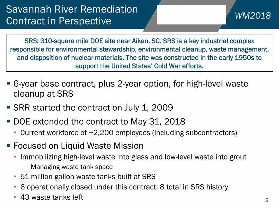
▪ 6-year base contract, plus 2-year option, for high-level waste cleanup at SRS
▪ SRR started the contract on July 1, 2009
▪ DOE extended the contract to May 31, 2018
• Current workforce of ~2,200 employees (including subcontractors)
▪ Focused on Liquid Waste Mission
• Immobilizing high-level waste into glass and low-level waste into grout
– Managing waste tank space
• 51 million-gallon waste tanks built at SRS
• 6 operationally closed under this contract; 8 total in SRS history
• 43 waste tanks left
Savannah River Remediation Contract in Perspective
3
SRS: 310-square mile DOE site near Aiken, SC. SRS is a key industrial complex
responsible for environmental stewardship, environmental cleanup, waste management,
and disposition of nuclear materials. The site was constructed in the early 1950s to
support the United States’ Cold War efforts.
WM2018
4
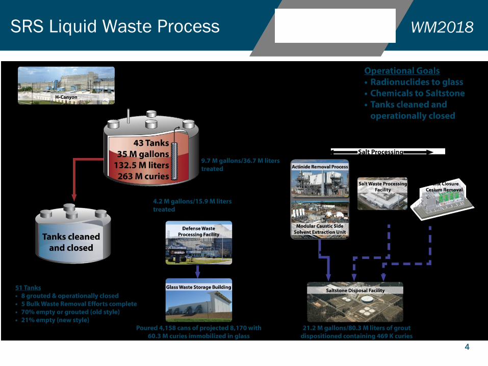
SRS Liquid Waste Process

WM2018
5
Background
▪ Melter 2 was shipped to SRS in 1989 with final assembly work completed on-site• Fabricated by Chicago Bridge and Iron of Cordova, AL
▪ Melter 2 operated from March 2003 until February 2017• 12 years longer than the 2 year design life
• 6 year longer life compared to Melter 1
▪ Produced over 4.9 million kgs (10.6 million lbs) of waste glass • 2819 glass filled canisters
▪ Retrofit with melt pool agitation bubblers in September 2010
▪ Operated since February 2013 with a failed Dome Heater D
WM2018
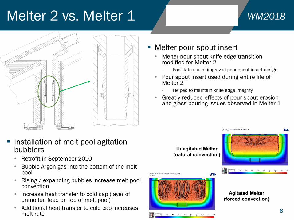
▪ Installation of melt pool agitation bubblers• Retrofit in September 2010
• Bubble Argon gas into the bottom of the melt pool
• Rising / expanding bubbles increase melt pool convection
• Increase heat transfer to cold cap (layer of unmolten feed on top of melt pool)
• Additional heat transfer to cold cap increases melt rate
6
Melter 2 vs. Melter 1
Unagitated Melter
(natural convection)
Agitated Melter
(forced convection)
▪ Melter pour spout insert• Melter pour spout knife edge transition
modified for Melter 2
– Facilitate use of improved pour spout insert design
• Pour spout insert used during entire life of Melter 2
– Helped to maintain knife edge integrity
• Greatly reduced effects of pour spout erosion and glass pouring issues observed in Melter 1

WM2018
▪ Experienced a failure of the pour spout heater on January 26, 2017
▪ Experienced a failure of the lower electrodes on February 1, 2017
▪ Cooling water observed dripping from L4 electrode stem
▪ Cooling water supply could have breached electrode stem wall or thermocouple cavity
▪ Breach would have resulted in contact between cooling water and molten glass which would have quenched glass at the breach location
7
Melter 2 End-of-Life
Lower Electrode
Stem
Cooling
water
supply/return
Pour Spout
Heater
Connection
WM2018
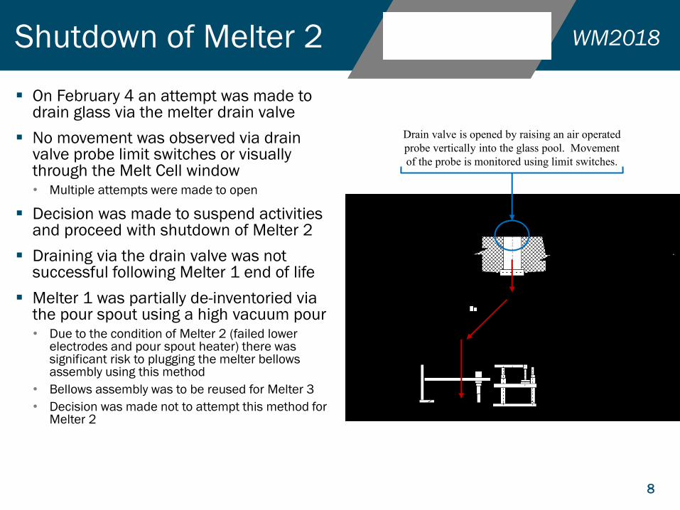
▪ On February 4 an attempt was made to drain glass via the melter drain valve
▪ No movement was observed via drain valve probe limit switches or visually through the Melt Cell window• Multiple attempts were made to open
▪ Decision was made to suspend activities and proceed with shutdown of Melter 2
▪ Draining via the drain valve was not successful following Melter 1 end of life
▪ Melter 1 was partially de-inventoried via the pour spout using a high vacuum pour• Due to the condition of Melter 2 (failed lower
electrodes and pour spout heater) there was significant risk to plugging the melter bellows assembly using this method
• Bellows assembly was to be reused for Melter 3
• Decision was made not to attempt this method for Melter 2
8
Shutdown of Melter 2
Drain valve is opened by raising an air operated
probe vertically into the glass pool. Movement
of the probe is monitored using limit switches.
WM2018
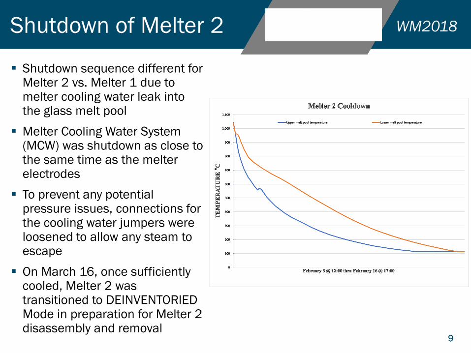
▪ Shutdown sequence different for Melter 2 vs. Melter 1 due to melter cooling water leak into the glass melt pool
▪ Melter Cooling Water System (MCW) was shutdown as close to the same time as the melter electrodes
▪ To prevent any potential pressure issues, connections for the cooling water jumpers were loosened to allow any steam to escape
▪ On March 16, once sufficiently cooled, Melter 2 was transitioned to DEINVENTORIED Mode in preparation for Melter 2 disassembly and removal
9
Shutdown of Melter 2
WM2018
▪ Completed with the support from SRNL• Provided video camera system and recording equipment
▪ Camera was suspended from the Melt Cell in-cell crane• Remotely operated from a station at the Melt Cell window
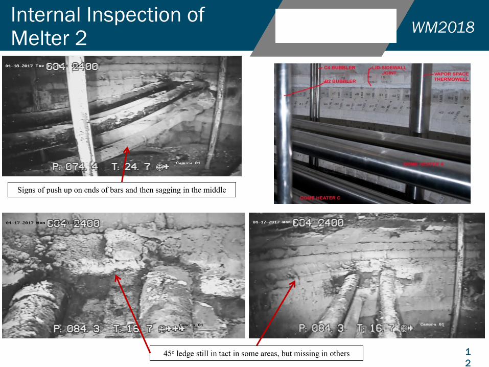
▪ Inspection revealed that overall condition appeared significantly more degraded that Melter 1• Expected due to 6 additional years of operation
▪ Inspection did not reveal any obvious issues with Dome Heater D that would have caused its failure
▪ Due to the level of glass in the melter, an inspection of the L4 electrode to potentially determine the cause of failure was not possible
▪ Melter Engineering and SRNL evaluated the inspection video and a joint paper has been released (SRNL-STI-2017-00428)
10
Internal Inspection of Melter 2

WM2018
11
Internal Inspection of Melter 2
WM2018
1
2
Signs of push up on ends of bars and then sagging in the middle
45o ledge still in tact in some areas, but missing in others
Internal Inspection of Melter 2

WM2018
13
Internal Inspection of Melter 2
Mound in center of melter
Visual observation of the sample determined the
glass was a “foamy” glass. This is likely due to the
introduction of gas into the melt pool which formed
a foam like layer on top of the melt pool. This
layer produced the glass observed in the sample as
it cooled when the melter was de-energized.
WM2018
▪ Disassembly is performed remotely using the Main Process Cell (MPC) crane• Main hoist has a capacity of 106 metric tons (117 US tons)
• Combined weight of the melter (completely filled with glass) and lifting yoke is approximately 95 tons
▪ Removal of 93 jumpers / components is required for melter removal
▪ Components were designated for re-use with Melter 3
• Melter Seal Pot
• Melter Bellows Assembly
• Melter Center Feed Tube
• Canister Positioning Arm
• Upper sections of the four melter agitation bubblers
▪ Components left installed on Melter 2 for disposal
• Melter Primary and Backup Off-gas Film Coolers
• Melter Vapor Space Thermowell
• Lower sections of the four melter agitation bubblers
14
Melter 2 Disassembly

WM2018
▪ Movement of the Melter Storage Box (MSB) from the FESV to the DWPF Inner Railroad Well (RRW)• Removed lid on MSB to inspect the internal area to ensure no foreign debris
• Loaded MSB onto a specifically design flatbed trailer that was wrapped to prevent contamination
• Moved trailer with MSB to the Inner RRW
▪ Restore operability of the rail system and the FESV crane system
• Unique systems that are only required to be operational for the MSB to FESV transport evolution
• Given the 14-year life of Melter 2, the systems had not been maintained for readiness
• Preventive and corrective maintenance was completed
• Testing of both systems and replacement of critical components was completed
– Five (5) sections of rail were replaced near the DWPF
15
Parallel Activities to Melter 2 Disassembly
WM2018
16
Melter 2 Removal from Melt Cell
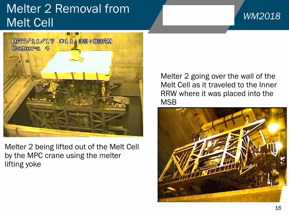
Melter 2 being lifted out of the Melt Cell by the MPC crane using the melter lifting yoke
Melter 2 going over the wall of the Melt Cell as it traveled to the Inner RRW where it was placed into the MSB

WM2018
17
Melter 2 Placement in Melter Storage Box
▪ A container was designed to fit inside the area normally filled by the seal pot
▪ Two 55-gallon drums were modified and placed in open areas to dispose of additional glass laden components
▪ System of nozzles was setup to spray a fixative (paint) over the MSB as it was moved from the Inner RRW to the Outer RRW.
▪ MSB surveyed in the Outer RRW and additional spraying was done by hand
WM2018
18
Melter 2 Removal and Transport to FESV
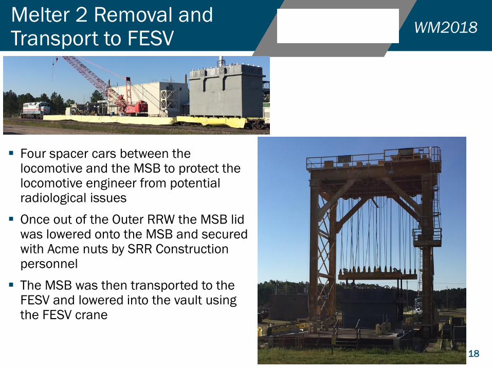
▪ Four spacer cars between the locomotive and the MSB to protect the locomotive engineer from potential radiological issues
▪ Once out of the Outer RRW the MSB lid was lowered onto the MSB and secured with Acme nuts by SRR Construction personnel
▪ The MSB was then transported to the FESV and lowered into the vault using the FESV crane

WM2018
19
Melter 3 Preparation & Testing
▪ Melter 3 placed in the mock-up cell in Building 717-F for final assembly and testing
• Melter 3 remotability and balance
• Melter 3 drain valve operation test
– Corrected a wiring issue related to drain valve limit switches
• Electrical testing
– Insulation resistance and continuity where applicable
– Corrected an issue with the electrical isolation of Melter Nozzle C3
• Hydrostatic testing of the melter cooling water system
▪ Startup glass loading
• Installed four (4) melter bubbler lower units prior to loading
• Used a camera system to monitor the glass loading
• Poured glass into multiple nozzles to ensure as level a surface as possible
• Loaded 1360 kilograms (3000 pounds) of startup glass
▪ Fabricated and installed removable covers over electrical and process nozzles on the melter top-head and frame
WM2018
20
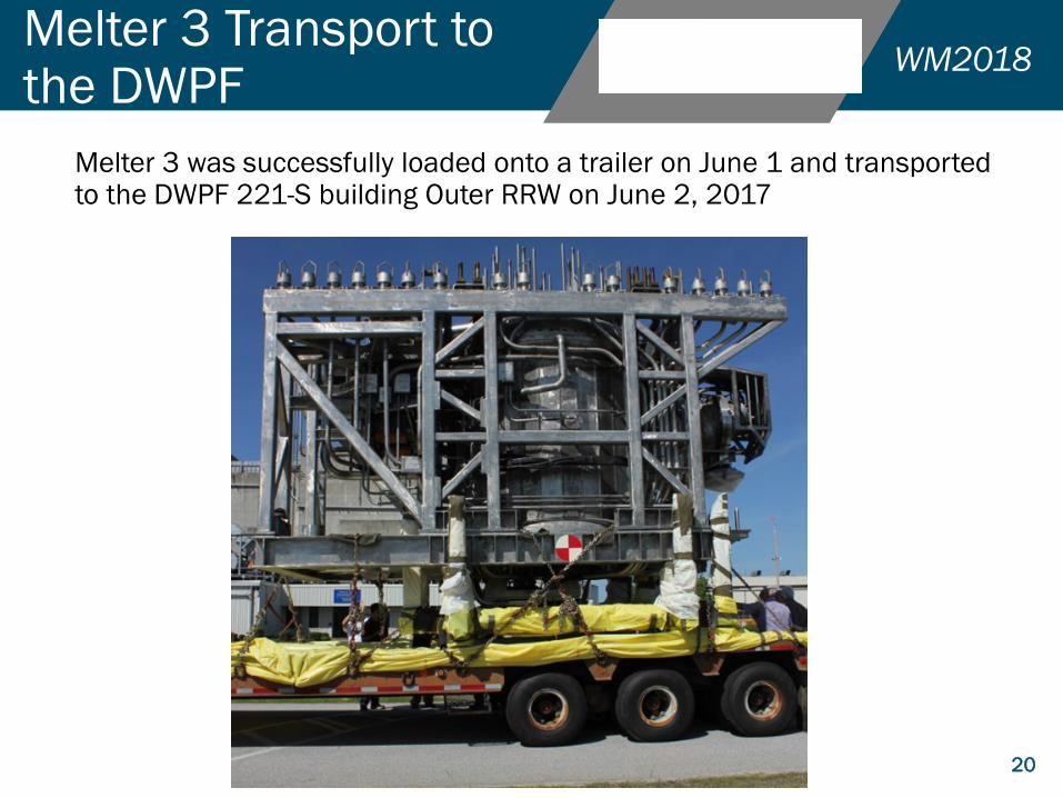
Melter 3 Transport to the DWPF
Melter 3 was successfully loaded onto a trailer on June 1 and transported to the DWPF 221-S building Outer RRW on June 2, 2017

WM2018
21
Melter 3 Pre-Installation Testing & Transport to Melt Cell
▪ Electrical testing was duplicated in the Outer RRW to ensure that no damage had occurred to Melter 3 during loading and transport to the DWPF
▪ Remote fit-up test of seal pot on Melter 3
• Done based on lesson learned from Melter 2 installation
• Only 1 seal pot is available so fit-up prior to transport to RRW was not possible
• Interference discovered between the Melter Dome Heater splash guard and the seal pot drain valve actuator
▪ Melter 3 was placed on the melter support beam in the Melt Cell on July 27, 2017
WM2018
22
Melter 3 Assembly & Testing in the Melt Cell
▪ Effort was made to install jumpers necessary to start-up the MCW System at the beginning of reassembly
• Begin circulating biocide through the system to prevent any potential corrosion from developing
▪ Two issues were discovered following restart of the MCW System.
• Potential leak in the system
– Found using remote camera equipment
– Corrected by removing the jumper and replacing the connector gaskets
• Low flow condition for Dome Heater C
– Initial investigation done on portion of system outside the cell (x-ray, line breaks) with no blockage discovered
– Flush rig was developed and deployed to send water through the Dome Heater C water channel on the melter frame
– Flushing activity was successful and system returned to normal flow once restarted
▪ During assembly, an interference was discovered between the electrical jumper for the Melter Off-gas primary isolation valve
• Due to stiffeners added to Melter 3 frame at the melter lifting yoke engagement points
– Not part of Melter 1 and Melter 2 design
• A new jumper was designed and fabricated to overcome the interference

WM2018
23
Melter 3 Assembly & Testing in the Melt Cell
▪ During electrical checks, the Dome Heater B transformer indicated an electrical short was present
• Various actions were performed to determine the root cause of the potential failure
• Visual inspection using the in-cell and crane cameras discovered that a small counterweight box on the melter seal pot was in contact with the copper piping that supplied cooling water to the Dome Heater B transformer
• A design change was implemented to remove the small counterweight box
▪ During functional testing of the Canister Positioning Arm (CPA) discovered that the arm would not close when commanded
• Troubleshooting indicated an electrical short was present at the CPA
• The CPA was removed and visual inspection found a crack in the Lexan plate and a potential short between two (2) pins on the electrical connector
• Decision was made to install the spare CPA which was completed following satisfactory electrical and functional checks

WM2018
24
Other Melter Related Activities Completed
▪ Design change to capability to switch between old and new melter electrode control cabinets
• New cabinets were in the procurement process at Melter 2 end-of-life
• Initially a melter replacement outage was needed to install new cabinets
• Change in direction to provide design that would allow switching capability
• New manual transfer switches and a new local control station were installed and tested prior to Melter 3 startup to successfully accomplish this goal
▪ Preventive Maintenance (PMs) on each melter heater control cabinet
▪ Checkout of various melter electrical jumpers
▪ Replacement of melter feed pump
▪ Replacement of melter feed pump variable frequency drive (VFD) due to obsolescence
▪ PMs on multiple electrical load centers
▪ Installation of new glass pour stream viewing camera
WM2018
25
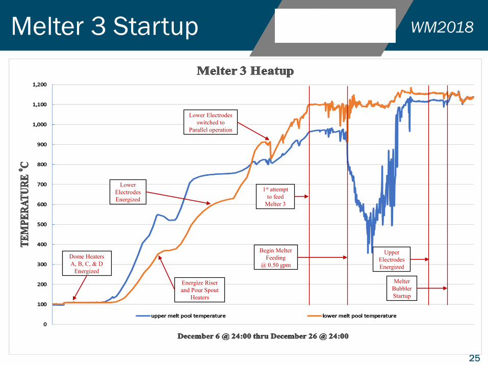
Melter 3 Startup
Energize Riser
and Pour Spout
Heaters
Lower
Electrodes
Energized
Lower Electrodes
switched to
Parallel operation
Begin Melter
Feeding
@ 0.50 gpm
Upper
Electrodes
Energized
Melter
Bubbler
Startup
Dome Heaters
A, B, C, & D
Energized
1st attempt
to feed
Melter 3

WM2018
26
Melter 3 Startup
▪ December 28, 2017 at 08:45 the DWPF initiated glass pouring from Melter 3
▪ Pouring of the 1st canister completed on December 29
▪ Since pouring the 1st canister, the DWPF produced 5 additional canisters until feed stock was no longer available
Melter Pour Stream Viewing Camera Image
DWPF Canister InfraRed image
at canister pour completion
WM2018
Questions?
27
WM2018
28
Melter 3 Startup
▪ Energized Melter Dome Heaters A, B, C, and D on December 6, 2017
▪ Heat-up rate limited to a nominal 10oC per hour to ensure proper dry-out and prevent potential damage to melter refractories
• Original recommendation for Melter 1 from the refractory manufacturer
▪ Heater controllers are initially operated in MANUAL and adjusted as necessary to maintain the nominal 10oC limit
▪ Melter Riser and Pour Spout heaters were energized once the lower glass melt pool temperature reached 350oC
▪ December 15: Melter lower electrodes were energized in Series (high voltage) once lower glass temperature reached 600oC
▪ Lower electrode Series/Parallel switch moved to Parallel (low voltage) once lower glass temperature reached 900oC and dome heater temperatures reached 960oC
• Parallel operation allows for higher current from the electrodes necessary for normal melter operation at 1100 to 1150oC
WM2018
29
Melter 3 Startup
▪ Lower electrode current increased to bring melt pool temperature to 1100oC so initial melter feeding could begin
▪ Attempt made on December 19 to transfer feed to the melter, however an issue arose with the 3-way valve in the melter feed jumper• Valve would not stop in the FEED MLTR position
• Troubleshooting determined that there was a bad or out of adjustment limit switch within the valve actuator
• Due to elevated radiological rates on the feed jumper, decision was made to install the spare melter feed jumper– Functional check was performed on spare jumper prior to installation within the melt cell
▪ On December 22 melter feeding began at 1.89 L/min (0.50 gpm)• Adjusted between 1.51 L/min (0.40 gpm) and 2.27 L/min (0.60 gpm) during melter charging
▪ Melter upper electrodes were energized once glass level reached 61 centimeters (24 inches)• Upper electrodes energized without issue
▪ Melter glass level reached 73.7 centimeters (29 inches) on December 25 and held there until a melter pour spout insert could be installed• Pour spout insert installed on December 27
▪ Melter charging to bring glass to the desired operating level continued until reaching 82.6 centimeters (32.5 inches)