Embed Size (px)
Citation preview
REPORT OF
PRELIMINARY GEOTECHNICAL SITE INVESTIGATION
KERSHAW COUNTY EXIT 87 OFFICE PARK
ELGIN, SOUTH CAROLINA S&ME Project No. 1611-04-450
Prepared For:
KERSHAW COUNTY ECONOMIC DEVELOPMENT OFFICE Post Office Box 763
Columbia, South Carolina 29020
Prepared By S&ME, Inc.
134 Suber Rd. Columbia, SC 29210
September 22, 2004
Report of Geotechnical Exploration S&ME Project No. 1611-04-450 Kershaw County Exit 87 Office Park, Elgin, SC September, 2004
2
1.0 Project Information
Information about the project was provided by Kershaw County Economic Development Of-
fice. The information provided included location, size and intended use of this site. We
noted that the site is moderately sloping with approximately 50 ft of surface relief. Access to
the site is off Whiting Way Road along the south border of the property. The site consists of
approximately 60 acres and is located northwest of Interstate 20 in Kershaw County. Cur-
rently, the site is mainly wood land with a small pond in the North West portion of the parcel.
A site vicinity map is included in the Appendix as Figure 1.
Construction at the site will likely consist of light to medium office facilities with the associ-
ated parking and drive areas.
Exploration Procedures
In exploring the site, we generally followed the approach described in our proposal 1614-
3704-04 dated August 30, 2004. Right-of-entry to perform borings and other fieldwork on
the property was granted with acceptance of our proposal.
A Field Assignment Sheet was prepared for the field exploration staff indicating minimum
boring depths, drilling method, sampling methods and depths, and backfilling method. Dur-
ing a site visit on September 14, 2004, a total of 5 boring locations were spaced around the
tract.
A brief summary of exploration and laboratory procedures is attached in the Appendix.
Site Work
After receiving notice to proceed, we notified the Palmetto Utility Protection Service (PUPS)
of our intent to drill at the site. S&ME checked proposed sampling points for conflicts with
Report of Geotechnical Exploration S&ME Project No. 1611-04-450 Kershaw County Exit 87 Office Park, Elgin, SC September, 2004
3
marked utilities, overhead power lines, tree limbs, or man-made structures during reconnais-
sance of the site.
S&ME laid out sampling points by measuring distances from existing site features and by
turning rough right angles from existing features marked on the aerial photograph. Sampling
point locations were marked in the field with small colored flags with the sampling point
numbers inscribed. Sampling points indicated on the attached “Boring Location Plan” must
be considered as approximate.
Top-of-ground elevations at sampling point locations were interpolated from the USGS 7.5-
minute topographic map. Interpolations between adjacent topographic contours were made
using the care and judgment ordinarily exercised in similar work. No survey of the boring
locations or elevations was conducted by S&ME.
Representatives of S&ME, Inc. visited the sites on September14 and 17, 2004. During the
visit we conducted the following activities:
• Observed site features and topography
• Laid out 5 boring locations by measuring from existing landmarks. • Advanced 4 soil test (STP) borings to a depth of 25 feet each and on seismic boring
to auger refusal at 63 feet.
• Water level measurements at the sampling locations were taken at the time of completion of the soil test borings and at least 24 hours after drilling.
Standard Penetration Testing and Sampling Exploration work included five SPT borings (B-1 to B-5) advanced to 25-63 ft. using a ATV-
mounted drill rig. Hollow-stem continuous flight augers were used to advance the borings into
the ground. Groundwater levels in the boring holes were measured at the time of completion.
Report of Geotechnical Exploration S&ME Project No. 1611-04-450 Kershaw County Exit 87 Office Park, Elgin, SC September, 2004
4
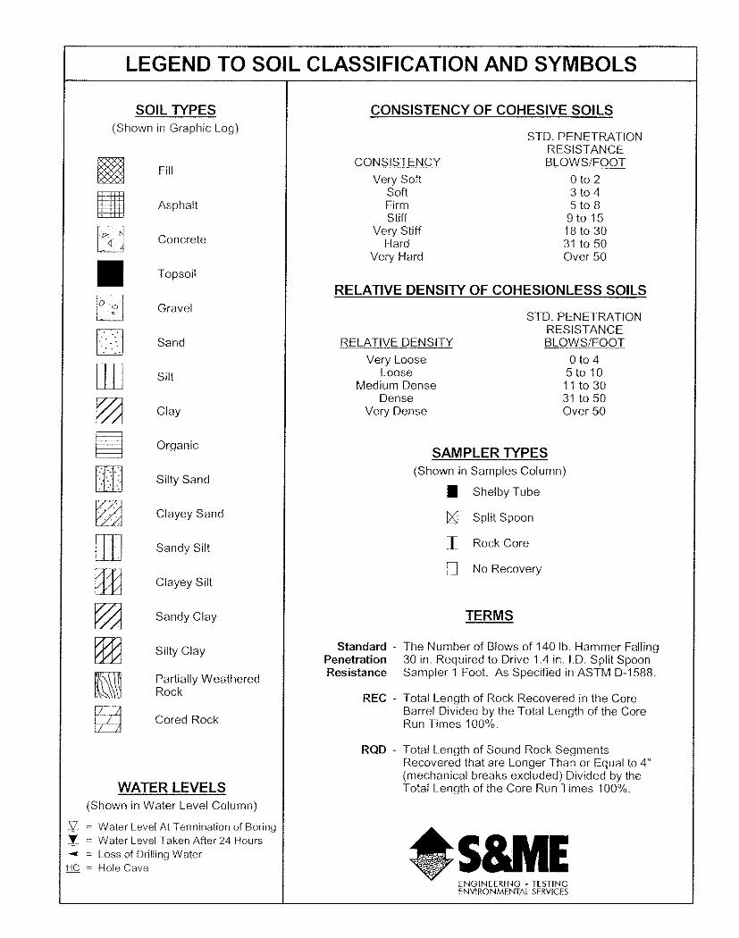
Standard Penetration Tests were performed at designated intervals in general accordance
with ASTM D 1586 to provide an index for estimating soil strength and density. In conjunc-
tion with the penetration testing, split-spoon soil samples were recovered for soil classifica-
tion and potential laboratory testing. The SPT data is attached in the Appendix
Site Conditions
The site is bordered by Whiting Way Road to the south, White Pond Road to the south west
and Haig Creek to the north east. The majority of the site is currently wooded with mature
pines and few small hardwoods. Ground cover on the site consists of mainly thin underbrush
with some dense pockets of vegetation. No rock outcroppings were observed on the site. No
existing structures were noted on site.
Topography The site is located in the Coastal Plains Province of South Carolina. The site is moderately
sloping with approximately 50 feet of surface relief. Surface elevation was estimated as
ranging from about 250 ft at the south side of the site to about 200 ft. near Haig Creek to the
north east. Elevations given are above mean sea level estimated from the USGS topographic
map for Kershaw County.
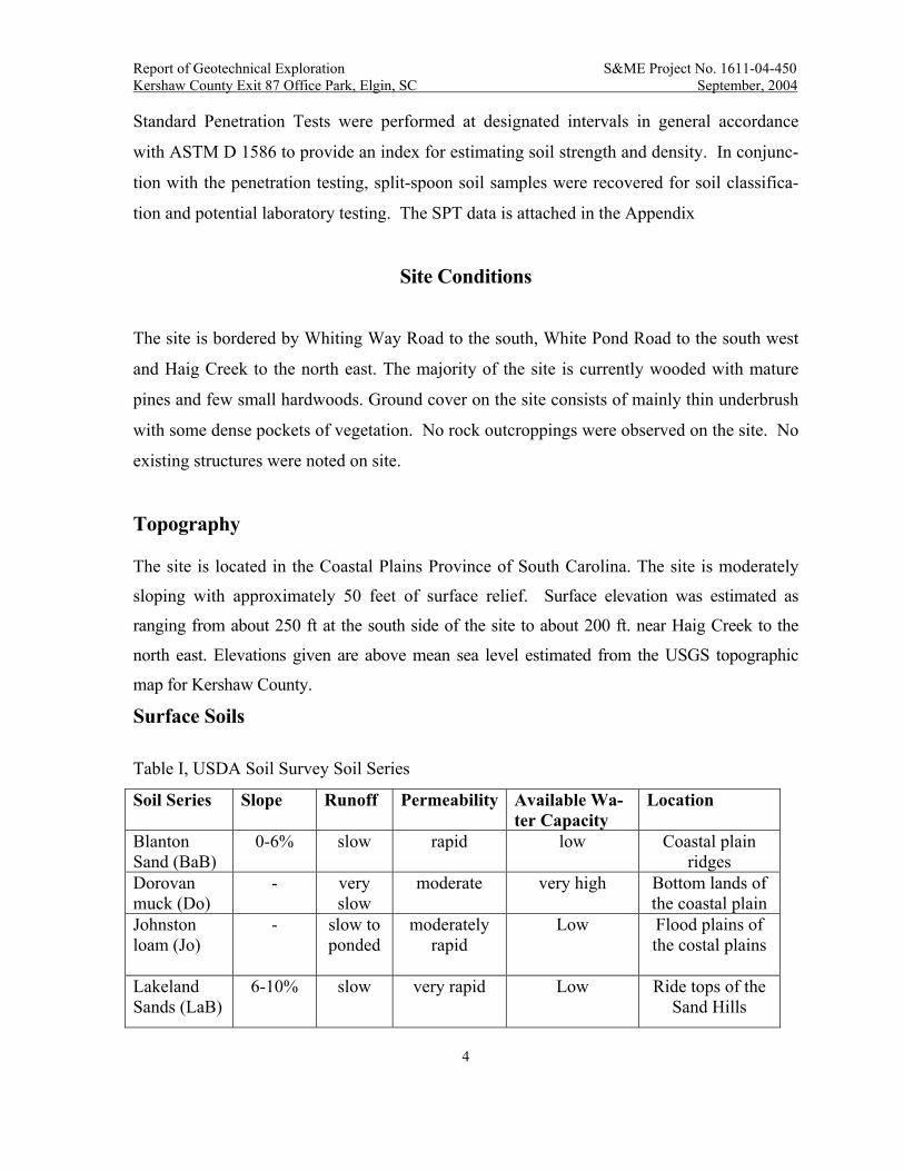
Surface Soils
Table I, USDA Soil Survey Soil Series
Soil Series Slope Runoff Permeability Available Wa-ter Capacity
Location
Blanton Sand (BaB)
0-6% slow rapid low Coastal plain ridges
Dorovan muck (Do)
- very slow
moderate very high Bottom lands of the coastal plain
Johnston loam (Jo)
- slow to ponded
moderately rapid
Low Flood plains of the costal plains
Lakeland Sands (LaB)
6-10% slow very rapid
Low Ride tops of the Sand Hills

Report of Geotechnical Exploration S&ME Project No. 1611-04-450 Kershaw County Exit 87 Office Park, Elgin, SC September, 2004
5
The site lies within the White Sand Hills Physiographic Region of the Upper Coastal Plain of
South Carolina. The White Sand Hills form the most inland portion of the coastal plain and
are underlain by mostly sandy Cretaceous age sediments of the Black Mingo and Middendorf
formations. These soils were eroded from a range of mountains in the northwest portion of
the state approximately 65,000,000 years ago and laid down in their present positions as fan
deposits, where they have weathered in place. In many areas groundwater is relatively shal-
low and supports heavy forest cover. Fresh soil exposures are typically white, but become
pink, purple or rusty orange with weathering. Iron-oxide cemented sandstone beds are com-
mon.
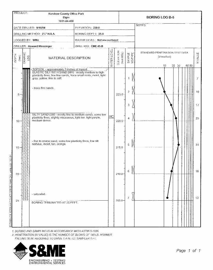
3.3 Interpreted Subsurface Profile The generalized subsurface conditions at the site are described below. For detailed descriptions and stratification at a particular boring location, the respective SPT boring log record should be reviewed.
Our borings encountered about 3 to 6 in. of topsoil at the boring locations. Underlying the
topsoil, our borings encountered generally three layers of subsurface soils, which are grouped
on the basis of data from the STP borings and our observation and manipulation of the
recovered soil samples.
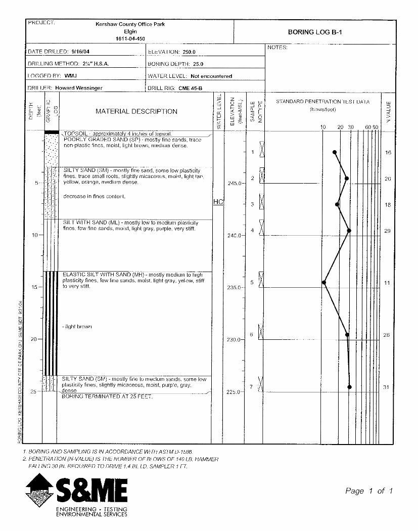
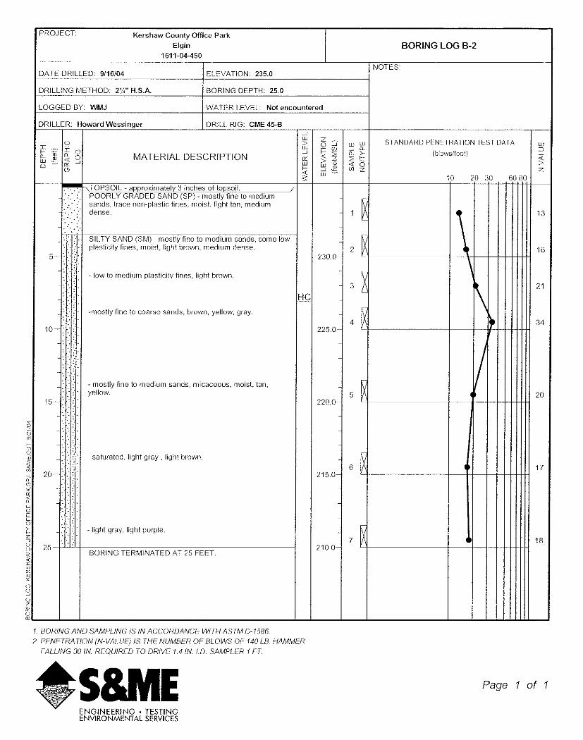
In borings B-1 and B-2 the upper approximately 3-1/2 ft. of the boring consists mainly me-
dium dense poorly graded sands (SP) Standard Penetration Test (SPT) N-values in this strata
ranged from 13 to 16 blows per foot (bpf). Beneath the poorly graded sand layer in boring B-
2, medium dense silty sand (SM) was encountered to termination of the boring at about 25 ft.
SPT-N values in the silty sands ranged from 17 to 34 bpf. In boring B-1 medium dense silty
sand was encountered from about 3-1/2 ft/ to approximately 6.5 ft. with N values in this
strata ranging from 18 to 26 bpf. The silty sand layer is underlain by a stiff silt with sand
(ML) layer from approximately 6-1/2 ft. to about 13-1/2 ft. with N-values ranging from 29 to
11 bpf. Elastic silt with sand (MH) was encountered from approximately 13-1/2 ft. to 23-1/2
Report of Geotechnical Exploration S&ME Project No. 1611-04-450 Kershaw County Exit 87 Office Park, Elgin, SC September, 2004
6
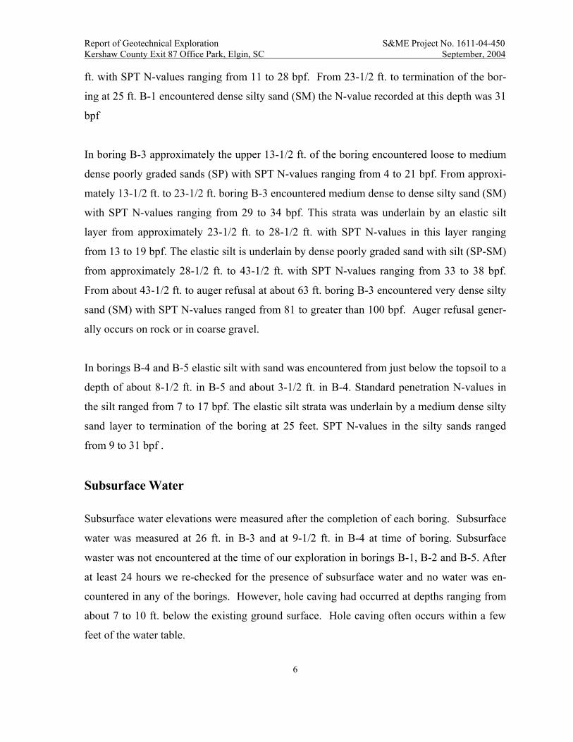
ft. with SPT N-values ranging from 11 to 28 bpf. From 23-1/2 ft. to termination of the bor-
ing at 25 ft. B-1 encountered dense silty sand (SM) the N-value recorded at this depth was 31
bpf
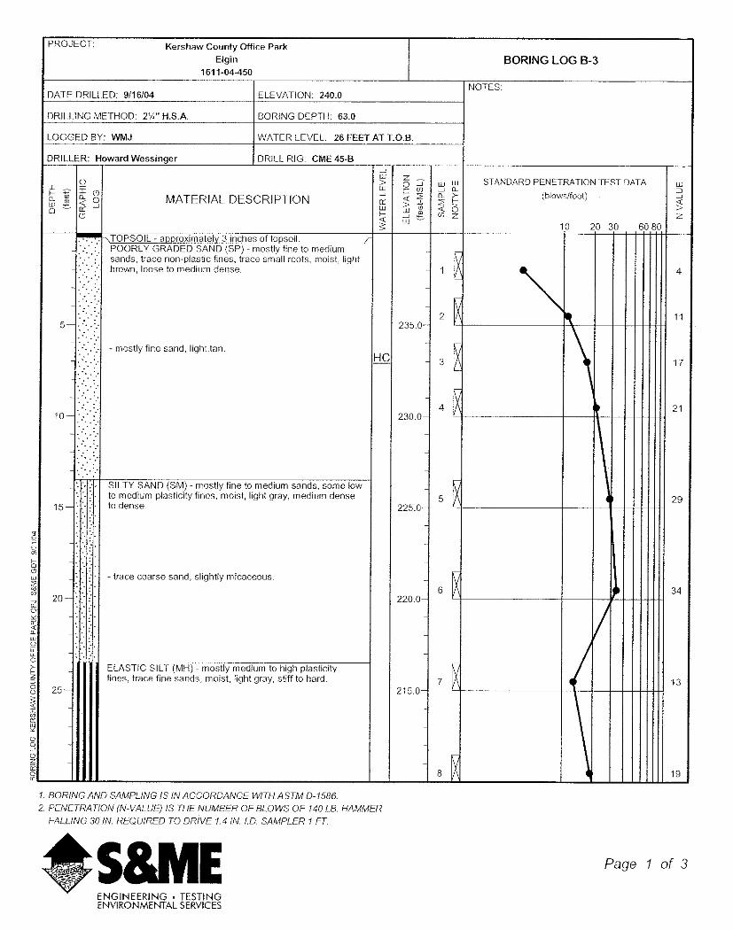
In boring B-3 approximately the upper 13-1/2 ft. of the boring encountered loose to medium
dense poorly graded sands (SP) with SPT N-values ranging from 4 to 21 bpf. From approxi-
mately 13-1/2 ft. to 23-1/2 ft. boring B-3 encountered medium dense to dense silty sand (SM)
with SPT N-values ranging from 29 to 34 bpf. This strata was underlain by an elastic silt
layer from approximately 23-1/2 ft. to 28-1/2 ft. with SPT N-values in this layer ranging
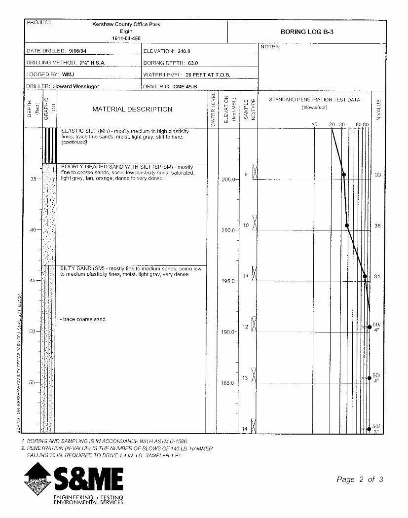
from 13 to 19 bpf. The elastic silt is underlain by dense poorly graded sand with silt (SP-SM)
from approximately 28-1/2 ft. to 43-1/2 ft. with SPT N-values ranging from 33 to 38 bpf.
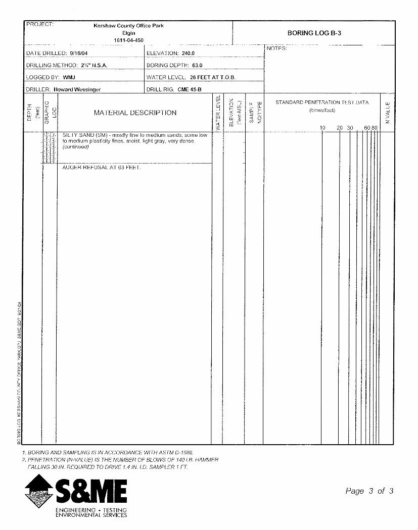
From about 43-1/2 ft. to auger refusal at about 63 ft. boring B-3 encountered very dense silty
sand (SM) with SPT N-values ranged from 81 to greater than 100 bpf. Auger refusal gener-
ally occurs on rock or in coarse gravel.
In borings B-4 and B-5 elastic silt with sand was encountered from just below the topsoil to a
depth of about 8-1/2 ft. in B-5 and about 3-1/2 ft. in B-4. Standard penetration N-values in
the silt ranged from 7 to 17 bpf. The elastic silt strata was underlain by a medium dense silty
sand layer to termination of the boring at 25 feet. SPT N-values in the silty sands ranged
from 9 to 31 bpf .
Subsurface Water
Subsurface water elevations were measured after the completion of each boring. Subsurface
water was measured at 26 ft. in B-3 and at 9-1/2 ft. in B-4 at time of boring. Subsurface
waster was not encountered at the time of our exploration in borings B-1, B-2 and B-5. After
at least 24 hours we re-checked for the presence of subsurface water and no water was en-
countered in any of the borings. However, hole caving had occurred at depths ranging from
about 7 to 10 ft. below the existing ground surface. Hole caving often occurs within a few
feet of the water table.
Report of Geotechnical Exploration S&ME Project No. 1611-04-450 Kershaw County Exit 87 Office Park, Elgin, SC September, 2004
7
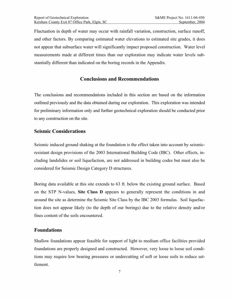
Fluctuation in depth of water may occur with rainfall variation, construction, surface runoff,
and other factors. By comparing estimated water elevations to estimated site grades, it does
not appear that subsurface water will significantly impact proposed construction. Water level
measurements made at different times than our exploration may indicate water levels sub-
stantially different than indicated on the boring records in the Appendix.
Conclusions and Recommendations
The conclusions and recommendations included in this section are based on the information
outlined previously and the data obtained during our exploration. This exploration was intended
for preliminary information only and further geotechnical exploration should be conducted prior
to any construction on the site. Seismic Considerations
Seismic induced ground shaking at the foundation is the effect taken into account by seismic-
resistant design provisions of the 2003 International Building Code (IBC). Other effects, in-
cluding landslides or soil liquefaction, are not addressed in building codes but must also be
considered for Seismic Design Category D structures.
Boring data available at this site extends to 63 ft. below the existing ground surface. Based
on the STP N-values, Site Class D appears to generally represent the conditions in and
around the site as determine the Seismic Site Class by the IBC 2003 formulas. Soil liquefac-
tion does not appear likely (to the depth of our borings) due to the relative density and/or
fines content of the soils encountered.
Foundations Shallow foundations appear feasible for support of light to medium office facilities provided
foundations are properly designed and constructed. However, very loose to loose soil condi-
tions may require low bearing pressures or undercutting of soft or loose soils to reduce set-
tlement.

Report of Geotechnical Exploration S&ME Project No. 1611-04-450 Kershaw County Exit 87 Office Park, Elgin, SC September, 2004
8
Grade Slab Support and Construction
It is likely that grade slabs on the site will be supported by shallow on-site cut or fill soils. The
in-place poorly graded and silty sands similar to those penetrated by our borings will
generally provide adequate support to soil-supported slabs-on-grade, assuming proper
preparation, moisture control, and compaction of the subgrade for static load conditions.
Elastic silts encountered at or near the ground surface in borings B-4 and B-5 may require
some stabilization or undercutting prior to placement of grade slabs.
Potential Borrow Material and Site Preparation The poorly graded sands encountered at the site are suitable for use as structural fill. The
silty sand can also likely be used as structural fill; however, the high fines content of some of
these soils will result in the material being difficult to dry if it is allowed to become wet. Care
should be exercised during site work to segregate excessively wet fine-grained sols from
structural fill. The elastic silts encountered at this site should be avoided as use for structural
fill; however, this material could possibly be used in deep (greater than 10 ft.) parking area
fills.
Site preparation may require ditching to lower subsurface water levels prior to deep cuts or
trenching for utility lines. Care should be taken to seal the surface of building pads and
pavement subgrades if rain is pending. Fill material should maintain a slope of at least
1V:100H to allow runoff of rain water during site grading.
Qualifications of Report
This report has been prepared in accordance with generally accepted geotechnical engineering
practice for specific application to this project. The conclusions and recommendations
contained in this report were based on the applicable standards of our profession at the time this
report was prepared. No other warranty, express or implied, is made.
Report of Geotechnical Exploration S&ME Project No. 1611-04-450 Kershaw County Exit 87 Office Park, Elgin, SC September, 2004
9
The analyses and recommendations submitted in this report are based, in part, upon the data
obtained from the subsurface exploration. The nature and extent of variations between the
borings may not become evident until construction. Due to the distance between each boring,
subsurface conditions can be expected to vary from the conditions described herein.
In the event that any changes in the nature, design, or location of the project are planned, the
conclusions and recommendations contained in this report will not be considered valid unless
the changes are reviewed and conclusions of the report modified or verified in writing by us.
We recommend that S&ME, Inc. be provided the opportunity to review the final design plans
and specifications in order to ensure that earthwork and foundation recommendations are
properly interpreted and implemented.

APPENDIX
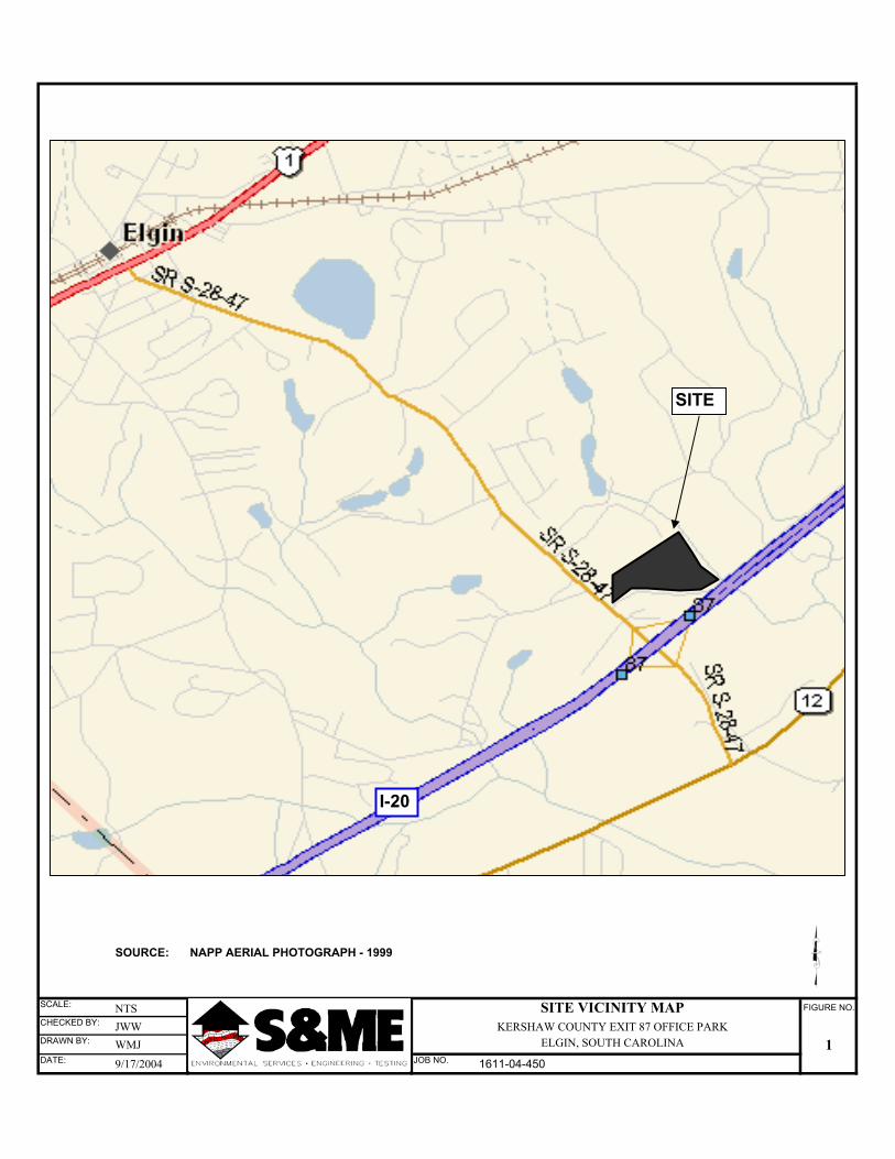
SOURCE: NAPP AERIAL PHOTOGRAPH - 1999
SCALE: NTS SITE VICINITY MAP FIGURE NO.
CHECKED BY: JWW KERSHAW COUNTY EXIT 87 OFFICE PARKDRAWN BY: WMJ ELGIN, SOUTH CAROLINA 1DATE: 9/17/2004 JOB NO. 1611-04-450
SITE
I-20
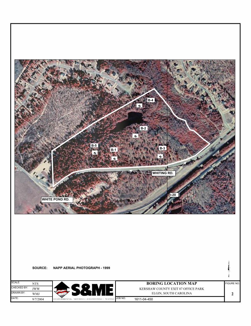
SOURCE: NAPP AERIAL PHOTOGRAPH - 1999
SCALE: NTS BORING LOCATION MAP FIGURE NO.
CHECKED BY: JWW KERSHAW COUNTY EXIT 87 OFFICE PARKDRAWN BY: WMJ ELGIN, SOUTH CAROLINA 2DATE: 9/7/2004 JOB NO. 1611-04-450
WHITING RD.
WHITE POND RD.I-20
B-1
B-2
B-3
B-4
B-5
PROCEDURES
Configuration and Layout of Borings Checks for Hazardous Conditions - After receiving notice to proceed, we notified the Palmetto Utility Protection Service (PUPS) of our intent to drill at the site. PUPS is operated by the major water, sewer, electrical, telephone, CATV, and natural gas suppliers of South Carolina. PUPS forwarded our location request to the participating utilities. Location crews then marked buried lines with colored flags within 72 hours. S&ME checked proposed sampling points for conflicts with marked utilities, overhead power lines, tree limbs, or man-made structures during reconnais-sance of the site. Staking of Borings - S&ME laid out the borings by measuring distances from existing site fea-tures and by turning rough right angles from existing features marked on the aerial photograph. Boring locations were marked in the field with small colored flags with the boring numbers in-scribed. Boring locations indicated on the attached “Boring Location Plan” must be considered as approximate. Boring Elevations - Top-of-ground elevations at borings were interpolated from USGS topog-raphic mapping data and should be considered approximate for demonstration purposes only. No survey of the boring locations or elevations was conducted by S&ME.
Boring and Sampling Procedures Field Boring Records - The subsurface conditions encountered during drilling were reported on a field test boring record by the chief driller. The record contains information about the drilling method, samples attempted and sample recovery, indications of materials in the borings such as coarse gravel, cobbles, etc, and indications of materials encountered between sample intervals. Field boring records are retained at our office. Soil Test Borings by Hollow Stem Auger - Soil test borings were advanced at the marked loca-tions by hollow-stem auger and are denoted “B-“on the boring location plan. All borings were advanced to their assigned depths or to auger refusal. In each boring - penetration testing were performed in general accordance with ASTM D1586, “Standard Test Method for Penetration Test and Split Barrel Sampling of Soils. At regular intervals, soil samples were obtained with a stan-dard 1.4 inch I. D., two-inch O. D., split barrel sampler. The sampler was first seated six inches to penetrate any loose cuttings, and then driven an additional 12 inches with blows of a 140-pound hammer falling 30 inches. The number of hammer blows required to drive the sampler through the two final six inch increments was recorded as the penetration resistance (SPT N) value. The N-value, when properly interpreted by qualified professional staff, is an index of the soil strength and foundation support capability. Borehole Closure - Following collection of relevant geotechnical data, boreholes were filled by slowly pouring auger cuttings into the open hole such that minimal “bridging” of the material oc-curred in the hole. Backfilling of the upper two feet of each hole was tamped as heavily as possi-ble with a shovel handle or other hand held equipment, and the backfill crowned to direct rainfall away on the surface. Where boreholes exceeded five feet in depth, a plastic hole plug was firmly tamped into place within the backfill at a depth of about two feet.
Water Measurements - Water level readings were made in the open boreholes immediately after completing drilling and withdrawal of the tools and at least 24 hours after drilling. Preservation and Handling of Recovered Earth Materials Preservation and Transporting of Soil Samples with Control of Field Moisture – Procedures for preserving soil samples obtained in the field and transportation of samples to the laboratory gen-erally followed those given in ASTM D 4220, “Standard Practice for Preserving and Transporting Soil Samples” for Group B samples as defined in Section 4. Representative samples split spoon samples were placed in suitably identified, sealed glass jars or plastic containers and transported to the labora-tory. Sample identification numbers on the containers corresponded to sample numbers recorded on field boring records or test pit records.
LABORATORY EVALUATION AND ARCHIVING OF SAMPLES Recovered field samples and field boring records were reviewed in the laboratory by the geotech-nical engineer. Soils were classified in general accordance with the visual-manual method de-scribed in ASTM D 2488, “Standard Practice for Description and Identification of Soils (Visual-Manual Method)”. With this information the geotechnical engineer prepared the final boring re-cords enclosed with this report.