Embed Size (px)
Citation preview

1
Report of the Ocean Engineering Committee
presented by Pierre Ferrant, Ecole Centrale de Nantes, France
(Committee Chairman)
September 19, 2008 Fukuoka, Japan

2
Committee Members
Prof. Pierre Ferrant (Chairman), Fluid Mechanics Laboratory, Ecole Centrale de Nantes, France
Prof. Martin Downie (Secretary), University of Newcastle upon Tyne, United Kingdom.
Dr Rolf Baarholm, Norwegian Marine Technology Research Institute, Norway.
Prof. Antonio C. Fernandes, Laboceano, Universidade Federal do Rio de Janeiro, Brasil
Dr. Nuno Fonseca, Instituto Superior Técnico, Portugal.
Dr Sa-Young Hong, Maritime and Ocean Engineering Research Institute, Moeri, Korea.
Prof. Shuichi Nagata, Institute of Ocean Energy, Saga University, Japan.
Dr Ir Jaap de Wilde, Maritime Research Institute Netherlands, The Netherlands.
Prof. Jianmin Yang, State Key Laboratory of Ocean Engineering, Shanghai Jiao Tong University, China

3
Meetings
Four Committee meetings were held respectively at:
• MARIN, Wageningen, the Netherlands, June 2006
• MOERI/KORDI, Daejon, Korea, December 2006
• Instituto Superior Técnico, Lisbon, Portugal, June 2007
• Shanghai Jiao Tong University, Shanghai, February 2008

4
Content of this Presentation
• Tasks assigned by the 24th ITTC• Structure of the report• State of the art reviews• Procedures• Benchmark study• Multiple scale model tests• Wind modelling• Concluding remarks

5
Tasks Assigned by the 24th ITTC (1)
State of the Art Reviews
Bottom founded structures, Stationary floating structures including moored and dynamically positioned ships, Modelling of waves, wind and current
• Comment on the potential impact of new developments on the ITTC.• Emphasize new experimental techniques and extrapolation methods
and the practical applications of computational methods to prediction and scaling.
• Identify the need for R&D for improving methods of model experiments, numerical modelling and full-scale measurements

6
Tasks Assigned by the 24th ITTC (2)
Review Existing Procedures• Laboratory Modelling of Multidirectional Irregular Wave Spectra (7.5-02-07-01.1)• Experiments with Offshore Platforms (7.5-02-07-03.1) • Model Testing in Regular Waves (7.5-02-07-03.2)• Turret Tanker Systems (7.5-02-07-03.4)• Hybrid Experiments and Numerical Simulations (7.5-02-07-03.45)
Review Validation of Prediction Techniques
• Identify and specify requirements for new benchmark data.• Outline a benchmark study using a simple geometric form for the application of unsteady RANS codes to wave load problems. The study should include validation against experimental data

7
Tasks Assigned by the 24th ITTC (3)
Develop New Procedures• Validation of frequency-domain codes• Validation of time-domain codes
Review Scaling Issues in Multiple-Scale Model TestsReview scaling issues associated with multiple-scale model tests in which, for example, some components become extremely small if proper geometric scaling is used.
Review Wind Modelling in Model BasinsIdentify requirements and carry out a review of wind modelling in model basins, including the physical modelling, simplified mathematical models and flow code analysis.
8
Structure of the Report
State of the Art Reviews
Section 2: Bottom-Founded StructuresSection 3: Stationary Floating Structures Section 4: Dynamically Positioned ShipsSection 5: Waves, Wind and CurrentSection 6: Hydroelasticity and ImpactSection 7: Renewable Energy SystemsSection 8: New Experimental TechniquesSection 9: Progress in CFD
Existing Procedures
Section 10:
• Multidirectional Irregular Wave Spectra• Experiments with Offshore Platforms• Model Testing in Regular Waves• Turret Tanker Systems• Hybrid Experiments and Numerical Simulations
New Documentation
Section 11: Benchmark Data for CFD ValidationSection 12: Validation of Software for Predicting Wave Loads and responses of Offshore StructuresSection 13: Multiple Scale Model TestingSection 14: Wind Modelling
Conclusions and Recommendations
Sections 15 & 16 respectively
Appendix
Section 17: Benchmark Data for validation of CFD codes

9
State of the Art Reviews

10
2 - Bottom Founded Structures
• Routine experimental and numerical procedures for estimating the fluid loading on bottom founded structures are well established. However, they remain a challenging area of research in extreme environmental conditions
• Ongoing research is required for novel structures of unusual geometry and interaction effects relating to the proximity of components in unexplored configu- rations.

11
• There are still fundamental fluid phenomena to investigate, particularly outside the conventionally defined regimes associated with flow separation and wave diffraction.
• As numerical/theoretical models become increasingly refined, and the scope of their capabilities widened, experiments and experimental techniques have to be devised for their validation.
Numerical wave run up calculations
Wellens et al ISOPE 2007
2 - Bottom Founded Structures

12
• Relative newcomers to the class of bottom founded structures are the offshore renewable energy converters, which introduce elements to the fluid loading problem not normally encountered in conventional mainstream offshore structures.
2 - Bottom Founded Structures

13
3-Stationary Floating Structures and Ships
Multiple methods in frequency domain and time domain: • Boundary element method• Finite element method• Finite Volumes, Finite Differences• Meshless methods• Hybrid schemes
dealing with coupled and non-linear phenomena:• Second order drift force• Sloshing• Green water and air gap• VIM and VIV • Multi-body interactions

14
Model experiments with new measuring techniques:• Particle image velocimetry to measure the velocity field for wave
impact, green water,. . .• Aerial and underwater motion tracking systems• Optical measurements of water surface motion
Measurements are used to verify the numerical simulations:• Hydrodynamics, VIM and installation of SPAR platform• Measurement of green water, air-gap and sloshing• Hydroelasticity of very large floating structures• Non-linear behavior of mooring lines and risers
3-Stationary Floating Structures and Ships

15
Coupled Systems
Floating platform motions Linear BEM methods
Mooring lines and risers finite difference, ormotions and tensions finite element methods
Coupling effects
Coupled solution by frequency or time domain methods
Work over the reporting period devoted to:
(a) Development and improvement of fully coupled time domain methods
(b) Improvement of frequency domain methods with the aim of reducing computational effort for engineering applications. Consistent stochastically linearization of the mooring forces is essential.
3-Stationary Floating Structures and Ships

16
Hydrodynamics of Multi-Body Interactions• Multi-body hydrodynamics in waves is in most cases calculated by linear BEM.
• Motions solved in the time domain to include specific external nonlinear effects.
• Higher Order BEM seems preferable since the computational effort is smaller for the same accuracy.
• As offshore activities expand and diversify, new challenges are posed to the scientific community also in the area of multi-body hydrodynamics (WEC farms)
3-Stationary Floating Structures and Ships

17
Side by side ships/platforms
• Typical problem: LNG offloading from the floating platform to the shuttle tanker.
• Linear models OK, except at resonant frequencies of the gap between vessels
• Existing semi-empirical methods to reduce the unrealistic high wave elevations between the two bodies have limitations
• Viscous flow models to be validated on such configurations
3-Stationary Floating Structures and Ships
Courtesy SBM

18
Further research may focus on:
• Complicated nonlinear behavior of stationary floating structures, such as green water, air-gap, multi-body interactions and VIM etc., in time domain
• New experimental techniques, such as particular image velocimetry, fibre optical sensors etc., need further maturing for day-to-day use in the basins.
• Numerical and Experimental Modelling of Floating Renewable Energy Systems to be developed
3-Stationary Floating Structures and Ships

19
Trends:
• Increasing complexity of the offshore operations, including: offloading by dynamically positioned shuttle tankers, dynamic tracking, disconnectable FPSOs with DP capabilities, etc.
• Autonomous under water vehicles with DP control
4-Dynamically Positioned Ships

20
Developments:
• DP contractors claim important developments in the control strategies of dynamic positioning systems, such as high precision control, DP for calm weather conditions and DP for minimum power consumption
• Model basins have worked on testing dynamic positioned vessels for novel structures or new applications of DP
• The focus in these papers is more on the application of the DP than on the (further development) of the DP control system.
4-Dynamically Positioned Ships

21
Extreme waves
• Freak (or Rogue) waves are now intensively studied (see Rogue Wave Symp., 2004, 2008)
• Reproduction of such extreme waves is very important as well as the investigation of their generation mechanism in real sea environments
5- Wind, Waves & Current

22
Reproduction of extreme waves• Wave focusing method
Clauss et al. (2005, 2006a) , Liu et al. (2005) Higher-order effects: Buchner et al. (2007), Ducrozet
(2006) • Wave-structure interactions
Kinoshita et al. (2006), Minami et al. (2006), Johannessen et al. (2006)
• Numerical wave tankIVOF: Buchner and Bunnik (2007), FEM vs. VOF: Bunnik
and Huijsmans(2005), Spectral: Ducrozet et al (2006)
5- Wind, Waves & Current
23
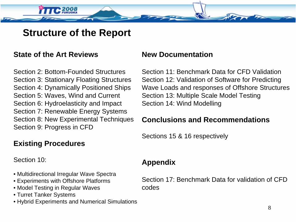
Shallow water waves
• Increase of shallow water floating storage facilities such as FSRU
• Increasing importance of low-frequency shallow water characteristics: Stansberg(2006)
– Wave-group induced low-frequency wave components
– Bound and free waves, reproduction and correction– Set-down effects: Theoretical model & model tests,
Voogt et al. (2005)
5- Wind, Waves & Current

24
Wind & current interactions
• Several commercial wave tests have been conducted combining waves with currents and winds, but few reports have been found for details of combined environments.
– Koo and Kim (2006) : wave-current interaction by NWT – Lee et al. (2006): experimental study on wave-current
interaction
5- Wind, Waves & Current

25
Hydroelasticity of VLFS
• Inherent weakened structural stiffness• Reduction of wave loads due to hydrostatic balance due to
structural deformation• Response time scale is comparable to wave periods
Research Trends:• Validation studies• Combined effects: bottom geometry, air cushion effects• Fully nonlinear time-domain methods
6- Hydroelasticity & Impact

26
Shape of fore structure of OWC chamber
2X/L
|W/A
|
-1 -0.8 -0.6 -0.4 -0.2 0 0.2 0.4 0.6 0.8 10
0.2
0.4
0.6
0.8
1
1.2
1.4λ/L=0.313, wo Chamberλ/L=0.313, δ=400, Lxa=0, a4=60m, Lc=62.5m, EIOWC=EIVLFS=EIoλ/L=0.313, Lxa=0, a4=60m, Lc= 0m, 0.01xEIOWC=EIVLFS=EIoλ/L=0.313, δ=400, Lxa=Lc, a4=C, Lc= 62.5m, EIOWC=EIVLFS=EIo
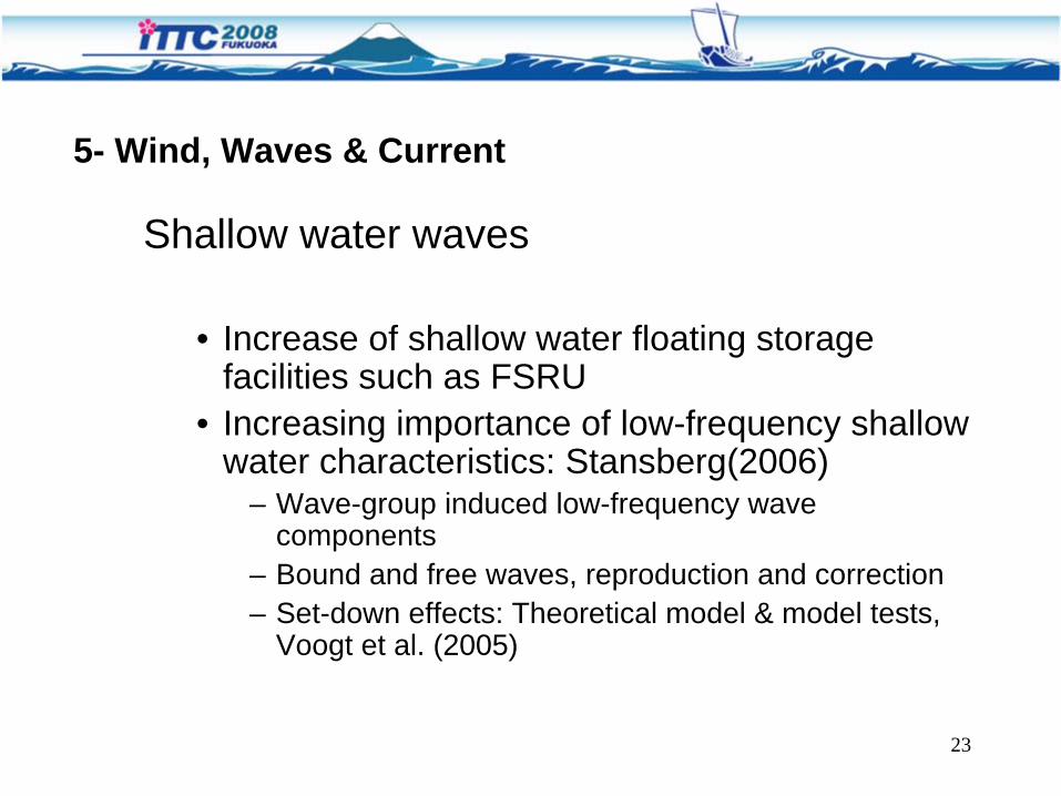
27
Whipping and Sloshing Impact• Consideration of hydroelasticity in analyzing impact
responsesDeuff et al, 2006, fluid-structure coupling using SPH
• Hydroelasticity related with sloshingMalenica et al.(2006), simplified asymptotic impact theoryRognebakke & Faltinsen (2006), entrapped air effectsWang & Kim(2007), FE analysis considering hydroelastic and
visco-elastic effects• Whipping & Springing
Storhaug & Moan(2006), experiments on whipping & springingMalenica et al, 2008
6- Hydroelasticity & Impact

28
Wave Energy Converters (WEC):Many different types :
Oscillating water columns
Moving or articulated bodies
Internal pendulum
Wave overtopping devices, etc…
Mostly systems based on moored bodies
7- Renewable Energy Systems

29
Wave Energy Converters (WEC):Numerous difficulties for Design and Modelling:
Modelling of power take-off mechanism
Strong nonlinear effects
Vortex shedding and viscosity affect efficiency
Multiple body interactions
Mooring lines damping
Real time monitoring of wave conditions for optimum control
Robust and cost-effective design is mandatory
A real challenge for EFD, CFD & Optimization !
7- Renewable Energy Systems

30Sailing offshore wind farm
Hywind floating wind turbine tests
Box girder grid type
floating wind turbine
7- Renewable Energy SystemsWind Energy:
Floating offshore wind farms based on Spars, TLPs, box girders are being studied.
Coupling effects between the support structure and the wind turbine when subjected to combined wind and wave loading must be modelled
Wind generation in model basins to be improved

31
Tidal & Marine Current EnergyIn order to evaluate the performance of the turbines orhydroplanes of these converters, a variety of numerical methods,such as RANS CFD, BEM, and Vortex Methods have been developed, and many experiments carried out.
7- Renewable Energy Systems

32
Particle Image VelocimetryNew experimental measuring techniques such as PIV and LDV, are becoming available for detailed investigation of the flow around the hull of a ship model or for instance the flow around a model of a complex offshore structures. These new techniques are particularly of interest for validation of CFD tools.
PIV measurements around bilge keels
PIV principle
8- New Experimental Techniques

33
Fiber Optics
Fibre optics is a particularly new experimental technique which is seeing its first applications in towing tanks and model basins. The technique is based on the same fibre optic techniques used in communication. Attractive when a large number of sensors is required in a small or a difficult to access area.
Fibre optic lines with Fibre Bragg Gratings (FBG)
8- New Experimental Techniques

34
Rapid Prototyping
Rapid prototyping technology is a group of manufacturing processes that enable the direct physical realization of 3D computer models.
Scale 1:300 demonstration model of drilling semi, manufactured with rapid prototyping
8- New Experimental Techniques
Optical Tracking Systems
Optical motion measurements of ship models, floater models or rigid bodies have become the standard in most towing tanks and model basins.
Underwater versions of such systems are now available for use in model basins.

35
Main Domains Impacted by CFD:Main Domains Impacted by CFD:
•• Wave Wave ModelingModeling, Extreme Waves, Extreme Waves•• Violent flows: Impact, Deck slamming, Green waterViolent flows: Impact, Deck slamming, Green water•• Coupled fluidCoupled fluid--structure interaction modellingstructure interaction modelling•• Cylinder flows, risers, VIVCylinder flows, risers, VIV•• WaveWave--structure interactions, including viscous structure interactions, including viscous
effects and/or extreme waveseffects and/or extreme waves•• . . .. . .
9- Progress in CFD

36
Developments of Numerical MethodsDevelopments of Numerical Methods
•• FiniteFinite--Volume methods with interface capturing Volume methods with interface capturing schemes (schemes (‘‘generalgeneral--purposepurpose’’ tools)tools)
•• Hybrid potential/viscous coupling schemesHybrid potential/viscous coupling schemes•• MeshlessMeshless methods show interesting capacities methods show interesting capacities
(robustness, complex configurations, multi(robustness, complex configurations, multi--physics, physics, adapted to massive parallel computing)adapted to massive parallel computing)
•• Efficient Efficient cartesiancartesian gridgrid--based methods with based methods with immersed boundaries techniqueimmersed boundaries technique
•• Validation & Verification, Estimation of uncertaintiesValidation & Verification, Estimation of uncertainties
9- Progress in CFD

37
•• Finite Finite Volumes+FreeVolumes+Free surface capturing:surface capturing:
9- Progress in CFD
Wave run up and pressure on GBS wind turbine support, Bredmose et al, OMAE2006

38
•• Hybrid potentialHybrid potential--viscous viscous flow couplingflow coupling–– Domain decompositionDomain decomposition–– Functional decompositionFunctional decomposition
Right: Focused wave on a TLP. Right: Focused wave on a TLP. Hybrid HOS/RANSE simulation Hybrid HOS/RANSE simulation ((LuquetLuquet et al, 2007)et al, 2007)
9- Progress in CFD

39
MeshlessMeshless methods:methods:Examples : SPH Examples : SPH
MPSMPS(See Violent flow Conference 2006)(See Violent flow Conference 2006)
9- Progress in CFD

40
•• Cartesian grid methods for massive parallel computationsCartesian grid methods for massive parallel computations(Domain decomposition, Immersed boundary techniques)(Domain decomposition, Immersed boundary techniques)
DommermuthDommermuth et al (2007)et al (2007)Yang et al (2007)Yang et al (2007)
9- Progress in CFD

41
•• Validation & VerificationValidation & Verification
•• Manufactured solutions for code benchmarking Manufactured solutions for code benchmarking
•• Uncertainty analysis, influence of uncertain input Uncertainty analysis, influence of uncertain input datadata
LucorLucor & & TryantafyllouTryantafyllou 20072007
9- Progress in CFD

42
Laboratory Modelling of Multidirectional Irregular Wave Spectra (7.5-02-07- 01.1)
• Minor changes to the text• References added
Model Tests in Regular Waves (7.5-02-07-03.2)
• A more complete analysis of the measured signals recommended in order to identify higher harmonic content, asymmetry and mean values,
• Small subsection of Uncertainty Analysis added,
• Lack of references with benchmark experimental data specific of offshore problems, however the committee is not aware of available and complete set of results including UA.
Truncation of Test Models and Integration with Numerical Simulations (7.5- 02-07-03.5)
• Minor changes and inclusion of a list of references
10- Procedures

43
Turret Tanker Systems (7.5-02-07-03.3) &Experiments with Offshore Platforms (7.5-02-07-03.1)
There are considerable areas of overlap between the Turret Tanker Systemsprocedure and the Experiments with Offshore Platforms procedure.
It is recommended that the procedure on Turret Tanker System is removed.The procedure on Experiments with Offshore Platforms was appropriately extended.
Hybrid Experiments and Numerical Simulations (7.5-02-07-03.4)
Procedure to carry out deep-water model tests in a test basin of limited depth using active control of the mooring lines.
Apparently, the technique described in the procedure is still not in use, therefore it is suggested that the procedure is reviewed when more experience is gained within active hybrid testing.
10- Procedures

44
Validation of Software for Predicting Wave Loads and Responses of Offshore Structures
• The OEC reviewed the procedure proposed by the seakeeping committee (Verification and validation of linear seakeeping codes) and proposes one common procedure for advancing ships and large volume stationary offshore structures.
• It is suggested that topics specific of offshore structures are added to a common procedure, such as: waterdepth effects, multi-body interactions, second order responses.
• Nonlinear effects should also be considered in future updates of the procedure (nonlinear geometric and free surface effects).
10- Procedures

45
Two candidates are proposed for a CFD benchmark study:
1. Existing ISSC experiments for wave run-up on a cylinder supplemented with new experiments including force measurements.
2. Existing non-oscillating and forced oscillation experiments on a circular cylinder in current
11- Benchmark Study

46
Wave Run-up around cylindersBackground
• Relevant for offshore structures in harsh environment where the air gap is an important parameter in design
• Available experimental data exists for wave loads on truncated circular and square cylinders and wave scattering around the cylinders
Objective
• To investigate how well state-of-the-art RANS codes (and other CFD techniques) can compute the wave scattering around a simple large volume structure due to monochromatic incident waves.
• Investigation of the free-surface wave elevation within a column radius distance around fixed vertical columns as well as wave loads on the columns
11- Benchmark Study (1)

47
Experiments performed at MARINTEK and MOERI
Snapshots from MARINTEK experiments
11- Benchmark Study (1)

48
Available experimental dataTime traces of calibrated incident waves at the position of the centre of the cylindersTime traces of the wave elevation of at the locations givenTime traces from wave force measurements (local and global).Harmonic analysis results for the wave elevation for zeroth, first and second harmonics for wave elevation and wave force.
Circular cylinder Square cylinder
11- Benchmark Study (1)

49
Test Conditions:
• Monochromatic incident waves• Two wave periods: 9s, 15s• Three wave steepness (H/λ): 1:30, 1:16 and 1:10
11- Benchmark Study (1)

50
Test set-up and test pipe
6 7
5
4
3
2
1
1 . V e r t ic a l s t r u ts .2 . L in e a r b e a r in g s3 . T e s t p ip e .4 . E n d p la te s .5 . D r iv e s h a f ts .6 . O s c i l la to r7 . 3 0 k W e le c t r ic m o to r .
6 7
5
4
3
2
1
6 7
5
4
3
2
1
1 . V e r t ic a l s t r u ts .2 . L in e a r b e a r in g s3 . T e s t p ip e .4 . E n d p la te s .5 . D r iv e s h a f ts .6 . O s c i l la to r7 . 3 0 k W e le c t r ic m o to r .
High Reynolds VIV test apparatus 200 mm smooth pipe
11- Benchmark Study (2)
Forced Oscillations of a Circular Cylinder in a Current

51
Three types of tests
Test set 1 : Vertical oscillation
Test set 2 :Horizontal tow
Test set 3 :Vertical oscillation,Horizontal tow
11- Benchmark Study (2)

52
Test data in ASCII format
• Time traces of measured in-line (Fx) and cross-flow (Fz) forces on the 3.52m long pipe for tow speed of 0.70 and 3.15m/s
• Cd and Cl coefficients for non-oscillating tests• Cd, Cm and Clv coefficients for forced oscillating test
11- Benchmark Study (2)

53
Stationary Cylinder in a Cross Flow• Re = 9.0E3, 9.0E4 and 5.5E5• Calculation of minimum of 40 vortex shedding cycles
of which 20 will be used for analysis • Time traces of calculated in-line (Fx) and cross-flow
(Fz) forces• Derivation of mean drag and oscillating lift
coefficients Cd and Cl• Analysis of vortex shedding frequency (St number
and spectrum)• Presentation of flow maps and vorticity plots
11- Benchmark Study (2)

54
Oscillating Cylinder in a Cross Flow
• Re = 9.0E3• Reduced velocity of Ur = UT/D = 5• Amplitude ratio of A/D = 0.3
11- Benchmark Study (2)

55
• Type of CFD model (RANS, URANS, LES, etc.)• Discretization method (finite elements, finite volumes,
finite differences etc.)• Turbulence model (e.g. 0-equation, 1-equation, 2-
equation, Reynolds-stress model, DES, LES, etc.)• Wall function (if applicable)• Grid (e.g. structured, unstructured, etc.)• Convergence• CPU time
11- Benchmark Study (2)
Description of the CFD Metod

56
Choice of a Realistic Case Study:Choice of a Realistic Case Study:•• FPSO (Floating Production Storage and Offloading)FPSO (Floating Production Storage and Offloading)•• L=300 mL=300 m•• 20 anchoring lines (taut leg mooring lines and polyester)20 anchoring lines (taut leg mooring lines and polyester)•• 100 different risers100 different risers•• Water Depth=1500 mWater Depth=1500 m
•• Submitted to random ocean waves (5Submitted to random ocean waves (5--15 s), wind and currents.15 s), wind and currents.
13- Multiple Scale Model Testing

57
Design of the Model Test:Design of the Model Test:
•• The central issue: define the scale of the model The central issue: define the scale of the model •• FroudeFroude scaling prevails due to the waves and lines responsesscaling prevails due to the waves and lines responses•• Typically, the scale factor ranges from 50 to 90Typically, the scale factor ranges from 50 to 90•• For the FPSO case study,For the FPSO case study, the compliant mooring lines avoid the compliant mooring lines avoid
horizontal drift but bring small horizontal restoring propertieshorizontal drift but bring small horizontal restoring properties..•• Second order low frequency resonant horizontal motion.Second order low frequency resonant horizontal motion.
13- Multiple Scale Model Testing

58
For the proposed case study:For the proposed case study:
•• Inertial effects are negligible;Inertial effects are negligible;•• The The staticsstatics (global restoring force plus the vertical angles at the top (global restoring force plus the vertical angles at the top
connections) maybe designed iteratively with userconnections) maybe designed iteratively with user--friendly computer friendly computer codescodes
•• The damping representation is based on The damping representation is based on diameter distortion, lines diameter distortion, lines concentration and truncationconcentration and truncation
•• However, the estimation of line damping remains an open issueHowever, the estimation of line damping remains an open issue
other cases such as CALM buoys would require specific analysisother cases such as CALM buoys would require specific analysis
13- Multiple Scale Model Testing

59
14.1 Physical Modelling In Model Basins
14.2 Wind Force Simulation By Empirical Models
14.3 Wind Simulation By CFD
14- Wind Modelling in Model Basins

60
Physical Modelling:Four methods to generate wind forces in model basins:
Kaasen E. K. et. al (2005)
1) Fixed banks of wind fansA method is proposed to calibrate the correct wind loads, rather than generate the correct wind velocity ( Buchner et al. , 2001)
Wind fan
2) Wind fans on model deck (Bobillier et al. 2000)
14- Wind Modelling in Model Basins

61
3) Spring-weight systemsa) Applied to wind-induced load in yaw motion
on turret moored vessels (Brown et al. 1998)b) Applied to controlled wind loads in surge,
sway, roll and yaw on a floating bridge (Nagata et al. 1999)
Spring
Wire
Sway
Roll
Yaw
Surge
W-4
W-3
W-1
W-2
Actuator
Floating Bridge
Layout of Actuators
Brown et al. 1998 Nagata et al. 1999

62
4) Wave tanks in wind tunnelsThe dynamic motions of an elastic floating bridge in waves and wind was studied by Murakoshi et al. (2004) in a wave tank with 12m length, 5.4m width and 0.22m depth, installed inside the test section of a wind tunnel. Wind velocity scaled using Froude’s law.
WIND TUNNEL
Spire Wave Generator
Wave absorbingsystem
Wave
Roughness Block
Floating Bridge

63
14.2 Wind Force Simulation By Empirical Models :
Widely accepted method for in-line and transverse forcesFluctuating wind velocity may be generated by superposition of harmonic
components
14.2 Wind Simulation by CFD :
Good agreement, but time consuming
Air flow around a shipRANS solver + k-εturbulence model
(Reddy et al 2000, El Moctar et al. 2003) Turbulent flow around bluff-bodies
RANS solver + various revised k-ε model,or LES (Murakami 1997 , Lübcke et al. 2001, Kuroda 2003,Tominaga et al. 2008)

64
Concluding remarks, suggestions
Development of procedures for identification & generation of highly nonlinear waves
Expansion of Marine Renewable Energies requires the development of CFD & EFD for a better design of WECs, Wind & Current turbines
Reference data needed for the validation of fluid-structure numerical models applied in Hydroelasticity & Impact problems
Development of Experimental Techniques: 3D PIV, Optical tracking, Free surface measurement….
New CFD methods are promissing. Their development should be continuously monitored
. . .

65
THANK YOU