Embed Size (px)
Citation preview

D2.1
Report on state-of-the-art of ‘functional distribution architecture’ frameworks and solutions
Project number: 730830
Project acronym: Safe4RAIL
Project title: Safe4RAIL: SAFE architecture for Robust
distributed Application Integration in roLling stock
Start date of the project: 1st of October, 2016
Duration: 24 months
Programme: H2020-S2RJU-OC-2016-01-2
Deliverable type: Report
Deliverable reference number: ICT-730830 / D 2.1/ 1.1
Work package WP2
Due date: December 2016 – M03
Actual submission date: 30th of December, 2016
Responsible organisation: SIE
Editor: Hongjie Fang
Dissemination level: Public
Revision: 1.1
Abstract:
Describes the state-of-the-art of functional distribution architecture frameworks including existing solutions from automotive, avionics and railway domains.
Keywords: ARINC 653, AUTOSAR, TCMS, DREAMS,
Functional distribution architecture framework
This project has received funding from the European Union’s Horizon 2020 research and innovation programme under grant agreement No 730830.

D2.1 - Report on state-of-the-art of ‘functional distribution architecture’ Frameworks and solutions
Safe4RAIL D2.1 Page II
Editor
Hongjie Fang (SIE)
Contributors (ordered according to beneficiary numbers)
Mirko Jakovljevic (TTT)
Azketa Ekain, Iñigo Odriozola (IKL)
Hongjie Fang (SIE)
Mario Münzer (TEC)
Dobromil Nenutil (UNI)
Achim Agster, Bernd Löhr (NEW)
Donatas Elvikis (IAV)
Disclaimer
The information in this document is provided “as is”, and no guarantee or warranty is given that the information is fit for any particular purpose. The content of this document reflects only the author’s view – the Joint Undertaking is not responsible for any use that may be made of the information it contains. The users use the information at their sole risk and liability.

D2.1 - Report on state-of-the-art of ‘functional distribution architecture’ Frameworks and solutions
Safe4RAIL D2.1 Page III
Executive Summary
The main task of WP2 of Safe4RAIL is to provide the “Functional Distribution” architecture concept for a mixed criticality embedded platform, offering an execution environment for multiple Train Control and Monitoring System (TCMS) application functions with a virtual bus inside the end-system.
SOTA analysis provides up to date relative knowledge to enable entering into the project as well as an initial alignment of SAFE4RAIL and CONNECTA participants. This document aims at developing a detailed SOTA analysis of existing ‘functional distribution architecture’ frameworks and suitable COTS solutions available in the market. This analysis takes into consideration domain specific standardised frameworks (AUTOSAR in automotive, ARINC 653 in avionics and TCN application profiles) and COTS solutions likely to be used for the development of such frameworks (e.g., RTOS, hypervisor).
This deliverable will be organized in this way: chapter 2 analyses the high level requirements of the next generation TCMS; chapter 3 analyses the AUTOSAR standard of automotive domain, as well as chapter 4 concentrates on the avionic domain by analysing ARINC 653 standard, chapter 5 focuses on the TCN application; since cross-domain architecture is being one of the popular research field, chapter 6 takes the ongoing project DREAMS into account, which is a suitable case for the cross-domain study. The analysis of high level requirements and domain specific standard or architecture concentrates on the technical and non-technical aspects. In chapter 7 a comparative analysis of the domain specific aspects will be done.

D2.1 - Report on state-of-the-art of ‘functional distribution architecture’ Frameworks and solutions
Safe4RAIL D2.1 Page IV
Contents
List of Figures ......................................................................................................... VII
List of Tables ......................................................................................................... VIII
Chapter 1 Introduction ......................................................................................... 1
1.1 Description of Safe4RAIL ................................................................................. 1
1.2 Mixed criticality application framework ............................................................. 2
Chapter 2 High-Level SOTA Requirements ........................................................ 4
2.1 Technical characteristics .................................................................................. 4
2.1.1 Configuration and management services ............................................................... 4
2.1.2 Time services ......................................................................................................... 7
2.1.3 Input/output services .............................................................................................. 7
2.1.4 Real-time support ................................................................................................... 7
2.1.5 Fault isolation ......................................................................................................... 8
2.1.6 Health monitoring ................................................................................................... 8
2.1.7 Security services .................................................................................................... 8
2.1.8 Requirements for underlying platform ...................................................................12
2.2 Non-technical characteristics ......................................................................... 12
2.2.1 A need for System Architecture Engineering Method ............................................12
2.2.2 Safety and the relevant standards .........................................................................14
2.2.3 Security and the relevant standards ......................................................................16
Chapter 3 SOTA in Automotive ..........................................................................20
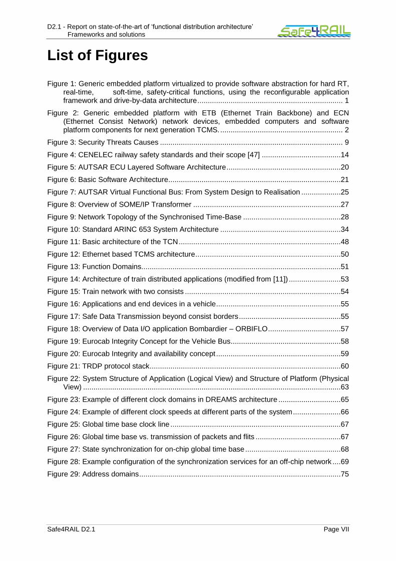
3.1 System architecture of AUTOSAR ................................................................. 20
3.1.1 Application Layer ..................................................................................................20
3.1.2 Runtime Environment (RTE) .................................................................................21
3.1.3 Basic Software (BSW) ...........................................................................................21
3.1.4 General Notes .......................................................................................................22
3.2 Technical characteristics ................................................................................ 22
3.2.1 Configuration and management services ..............................................................22
3.2.2 Inter-partition communication ................................................................................24
3.2.3 Time services ........................................................................................................27
3.2.4 Input/output services .............................................................................................28
3.2.5 Real-time support ..................................................................................................29
3.2.6 Fault isolation ........................................................................................................29
3.2.7 Health monitoring ..................................................................................................30
3.2.8 Security services ...................................................................................................31

D2.1 - Report on state-of-the-art of ‘functional distribution architecture’ Frameworks and solutions
Safe4RAIL D2.1 Page V
3.2.9 Requirements for underlying platform ...................................................................31
3.3 Non-technical characteristics ......................................................................... 32
3.3.1 Example products .................................................................................................32
3.3.2 Relationship to safety standards ...........................................................................32
3.3.3 Business model .....................................................................................................32
3.3.4 License cost ..........................................................................................................33
3.3.5 Support for third libraries .......................................................................................33
3.3.6 Legal considerations .............................................................................................33
Chapter 4 SOTA in Aerospace ............................................................................34
4.1 System architecture of ARINC 653 ................................................................ 34
4.2 Technical characteristics ................................................................................ 34
4.2.1 Configuration and management services ..............................................................35
4.2.2 Inter-partition communication ................................................................................37
4.2.3 Time services ........................................................................................................39
4.2.4 Input/output services .............................................................................................40
4.2.5 Real-time support ..................................................................................................40
4.2.6 Fault isolation ........................................................................................................40
4.2.7 Health monitoring ..................................................................................................43
4.2.8 Security services ...................................................................................................44
4.2.9 Requirements for underlying platform ...................................................................45
4.3 Non-technical characteristics ......................................................................... 45
4.3.1 Example products .................................................................................................45
4.3.2 Relationship to safety standards ...........................................................................47
Chapter 5 SOTA in Railway .................................................................................48
5.1 System architecture of TCMS ........................................................................ 48
5.1.1 Train Communication Network (TCN) ...................................................................48
5.1.2 TCMS as a function domain ..................................................................................51
5.1.3 The architecture of train distributed applications ...................................................52
5.2 Technical characteristics ................................................................................ 53
5.2.1 Configuration and management services ..............................................................53
5.2.2 Inter-partition communication ................................................................................54
5.2.3 Time services ........................................................................................................56
5.2.4 Input/output services .............................................................................................56
5.2.5 Real-time support ..................................................................................................57
5.2.6 Fault isolation ........................................................................................................58
5.2.7 Health monitoring ..................................................................................................59
5.2.8 Security services ...................................................................................................59

D2.1 - Report on state-of-the-art of ‘functional distribution architecture’ Frameworks and solutions
Safe4RAIL D2.1 Page VI
5.2.9 Requirements for underlying platform ...................................................................60
5.3 Non-technical characteristics ......................................................................... 61
5.3.1 Example products .................................................................................................61
5.3.2 Relationship to safety standards ...........................................................................61
5.3.3 Business model .....................................................................................................61
5.3.4 License cost ..........................................................................................................61
5.3.5 Support for third party libraries ..............................................................................62
5.3.6 Legal considerations .............................................................................................62
Chapter 6 SOTA in Cross-domain ......................................................................63
6.1 System architecture of DREAMS ................................................................... 63
6.2 Technical characteristics ................................................................................ 63
6.2.1 Configuration and management services ..............................................................63
6.2.2 Inter-partition communication ................................................................................70
6.2.3 Time services ........................................................................................................70
6.2.4 Input/output services .............................................................................................71
6.2.5 Real-time support ..................................................................................................71
6.2.6 Fault isolation ........................................................................................................71
6.2.7 Health monitoring ..................................................................................................71
6.2.8 Security services ...................................................................................................72
6.2.9 Requirements for underlying platform ...................................................................73
Chapter 7 Summary and conclusion..................................................................76
Chapter 8 List of Abbreviations .........................................................................78
Chapter 9 Bibliography .......................................................................................83
D2.1 - Report on state-of-the-art of ‘functional distribution architecture’ Frameworks and solutions
Safe4RAIL D2.1 Page VII
List of Figures
Figure 1: Generic embedded platform virtualized to provide software abstraction for hard RT, real-time, soft-time, safety-critical functions, using the reconfigurable application framework and drive-by-data architecture ...................................................................... 1
Figure 2: Generic embedded platform with ETB (Ethernet Train Backbone) and ECN (Ethernet Consist Network) network devices, embedded computers and software platform components for next generation TCMS. ........................................................... 2
Figure 3: Security Threats Causes ........................................................................................ 9
Figure 4: CENELEC railway safety standards and their scope [47] ......................................14
Figure 5: AUTSAR ECU Layered Software Architecture .......................................................20
Figure 6: Basic Software Architecture ...................................................................................21
Figure 7: AUTSAR Virtual Functional Bus: From System Design to Realisation ...................25
Figure 8: Overview of SOME/IP Transformer .......................................................................27
Figure 9: Network Topology of the Synchronised Time-Base ...............................................28
Figure 10: Standard ARINC 653 System Architecture ..........................................................34
Figure 11: Basic architecture of the TCN ..............................................................................48
Figure 12: Ethernet based TCMS architecture ......................................................................50
Figure 13: Function Domains................................................................................................51
Figure 14: Architecture of train distributed applications (modified from [11]) .........................53
Figure 15: Train network with two consists ...........................................................................54
Figure 16: Applications and end devices in a vehicle ............................................................55
Figure 17: Safe Data Transmission beyond consist borders .................................................55
Figure 18: Overview of Data I/O application Bombardier – ORBIFLO ...................................57
Figure 19: Eurocab Integrity Concept for the Vehicle Bus .....................................................58
Figure 20: Eurocab Integrity and availability concept ............................................................59
Figure 21: TRDP protocol stack ............................................................................................60
Figure 22: System Structure of Application (Logical View) and Structure of Platform (Physical View) ............................................................................................................................63
Figure 23: Example of different clock domains in DREAMS architecture ..............................65
Figure 24: Example of different clock speeds at different parts of the system .......................66
Figure 25: Global time base clock line ..................................................................................67
Figure 26: Global time base vs. transmission of packets and flits .........................................67
Figure 27: State synchronization for on-chip global time base ..............................................68
Figure 28: Example configuration of the synchronization services for an off-chip network ....69
Figure 29: Address domains .................................................................................................75

D2.1 - Report on state-of-the-art of ‘functional distribution architecture’ Frameworks and solutions
Safe4RAIL D2.1 Page VIII
List of Tables
Table 1: Binding Times in AUTOSAR Meta Model supported by Variant Handling ...............23
Table 2: Key terms in the TCN (IEC 61375 series) ...............................................................49
Table 3: TCN networks according to the technology class ....................................................49
Table 4: Allocation of functions/systems to Function Domains ..............................................52
Table 5: Message Format: Periodic or Sporadic Message on Virtual Link ............................74
Table 6: Message Format – Aperiodic Message with Connectionless Transfer ....................74
Table 7: List of Abbreviations ...............................................................................................82

D2.1 - Report on state-of-the-art of ‘functional distribution architecture’ Frameworks and solutions
Safe4RAIL D2.1 Page 1 of 85
Chapter 1 Introduction
1.1 Description of Safe4RAIL
Since the development of new technology and architectural concepts in automotive and avionic industries have led to significant and fast progress in safety, security and in the integration of new functions. To achieve similar industry developments in railway systems and take advantage of cross-industry synergies, the Shift2Rail JU multi-annual action plan has given high priority to create a specification that addresses the most common issues hindering the rolling stock efficiency, system optimization and interoperability within the European railway industry.
Under the above discussed background, the project “Safe4RAIL - Safe architecture for Robust distributed Application Integration in roLling stock” will provide a holistic architectural approach for building the next generation of Train Control and Monitoring Systems (TCMS). The main objective of Safe4RAIL is to define a fundamentally simplified electronic architecture and a common distributed/shared embedded computing and communication infrastructure for modular integration of all safety-, time- and mission-critical, and non-critical train functions (see Figure 1).
Figure 1: Generic embedded platform virtualized to provide software abstraction for hard RT, real-time, soft-time, safety-critical functions, using the reconfigurable application framework and drive-by-data architecture
Safe4RAIL investigates the baseline technologies and the capabilities required to create all the necessary preconditions for the development of a distributed integrated mixed-criticality embedded platform and architecture for rolling stock, which can host functions with the highest Safety Integrity Level (SIL) and integrate other less critical applications (Figure 2).
The baseline technologies include all embedded platform modules and components such as networks, middleware, real-time operating systems, with appropriate models of computation and communication, which support flexible application hosting and inter-process communication. The capabilities are all means and methodologies to define, configure and assess performance of embedded platform components, to align, verify, model and simulate their performance, and to structure scalable, reconfigurable, generic integrated modular architectures.
The generic embedded platform architecture provided by Safe4RAIL will allow safe and secure mixed-criticality integration and high levels of software abstraction (Figure 2) for

D2.1 - Report on state-of-the-art of ‘functional distribution architecture’ Frameworks and solutions
Safe4RAIL D2.1 Page 2 of 85
multiple partitions and multiple distributed applications on many shared and reconfigurable computing modules, with full system-level separation of logical and temporal behaviour to reduce logical system complexity.
Figure 2: Generic embedded platform with ETB (Ethernet Train Backbone) and ECN (Ethernet Consist Network) network devices, embedded computers and software platform components for next generation TCMS.
1.2 Mixed criticality application framework
One of the most important objectives of Safe4RAIL project is to develop an application framework concept for modular integration of TCMS applications, in order to host distributed safety-critical and non-critical application side-by-side on the same hardware platform in distributed next generation TCMS systems.
The goal of this mixed criticality application framework concept is to provide solutions to fulfil functional safety-critical and non-critical requirements and non-functional requirements (including security) that support functional distribution, interoperability, reconfiguration deterministic inter-partition communication, hardware and communication abstraction and virtual coupling of services, as if they would be hosted on a fault-tolerant distributed embedded computer.
Development of such an application framework will help to reduce hardware and power consumption as well as save the whole system weight. Limitations in integration of hard RT applications and design of gateway-free “flat” architectures as well as in integration of open and closed systems need to be conquered.
System-level partitioning and virtualization with temporal and spatial isolation in mixed criticality systems will be adopted in the design process. Temporal and spatial partitioning will help to simplify system integration and guarantee complete isolation of distributed functions in an integrated system. Only critical computing/networking resources attached to functional distribution, their configured use and interactions are to be certified.

D2.1 - Report on state-of-the-art of ‘functional distribution architecture’ Frameworks and solutions
Safe4RAIL D2.1 Page 3 of 85
After design of the application framework, the defined concepts and methodologies during the development process need to be proofed and the integrated system should be evaluated to reach SIL 4 level.
In the overall process of the work in WP2, the first step is to provide this deliverable as a technology feasibility analysis of the available domain specific COTS frameworks (e.g., AUTOSAR, ARINC 653) and commercial COTS solutions (e.g., hypervisors, safety RTOS) with respect to railway domain requirements. Collecting the railway domain specific requirements runs through the whole project and results in an internal release and a final release of deliverable D2.5. The D2.2 is to provide the detailed comparative analysis of cross-industry “functional distribution architecture” frameworks and solutions. After the SOTA analysis, the next generation TCMS framework which supports railway domain specific requirements will be defined in D2.3. In the D2.4, the TCMS framework design instantiations based on different solutions (e.g., AUTOSAR, hypervisors, safety RTOS) will be provided. The final proof-of-concept implementations and evaluations will be addressed in D2.6 and D2.7 respectively.

D2.1 - Report on state-of-the-art of ‘functional distribution architecture’ Frameworks and solutions
Safe4RAIL D2.1 Page 4 of 85
Chapter 2 High-Level SOTA Requirements
In this chapter, the high level requirements of the mixed criticality application framework for the next generation TCMS will be identified. These requirements are general requirements for architectural framework suitable for a mixed criticality embedded platform for the next TCMS. The SOTA analysis of the domain specific standards (AUTOSAR and ARINC 653) and technologies in the existing TCMS as well as cross-domain (e.g. DREAMS) are sources of the requirements. The detail railway specific requirements of the next generation TCMS framework are reported in D2.5. All the high level requirements in this deliverable are classified into either technical or non-technical categories.
2.1 Technical characteristics
Technical characteristics consist mainly of configuration/management services, time services, I/O services, etc., which are provided by the framework for the applications to access the underlying hardware and the system integrator to configure the system.
2.1.1 Configuration and management services
2.1.1.1 Configuration requirements
2.1.1.1.1 Management services
Infrastructure services
System management services refer to the services that a partition can invoke towards the virtualization layer or hypervisor. A partition can get the status of the virtualization layer or perform actions such as command a cold reset, a warm reset or a system halt to change the status of it.
Application services
The framework offers several reconfiguration services. It provides a partition the ability to change its own status or the status of other partition as well as make a request for a schedule plan change. Additionally, the framework includes global and local resource management services. On the one hand, global resource management services can obtain new configurations by selecting them from an offline-computed set of configurations or by computing new ones online. Alternatively, there can be made use of an external input to manually trigger a system-wide reconfiguration. On the other hand, local resource management comprises translating monitored information into abstract state levels or initiating local reconfigurations on its own.
2.1.1.1.2 Partition management
Infrastructure services
A partition is an execution environment with an isolated memory address space and limited execution time, so it can only address a pre-allocated area of memory and execute within pre-determined time slots in order to avoid the propagation of software errors among partitions. A memory manager guarantees the isolation of memory spaces and a cyclic

D2.1 - Report on state-of-the-art of ‘functional distribution architecture’ Frameworks and solutions
Safe4RAIL D2.1 Page 5 of 85
executive scheduler gives and takes away access to the processor when corresponds. The framework offers services to create and manage partitions.
Application services
The framework offers services to map an executable, i.e. a particular kind of file that is capable of being run as a program, to a partition with a configurable memory address space and execution slot.
2.1.1.1.3 Process management
Infrastructure services
In order to perform an optimal process management, the framework counts with threads, events and mutexes.
A thread is the smallest set of programmed instructions run in a sequence which can be managed by a scheduler. The main configuration parameters of a thread are the function that is executed and the priority. The framework offers services to create and manage threads.
Besides, an event is an element that is used to synchronize the execution of threads. Events are defined by a unique identifier and allow a thread to sleep in it until it is triggered by another element of the system. Events are distributed following the publish-subscribe pattern described in the application services subsection of the 2.1.1.1.6 Communication management chapter. The framework offers a service to create and manage events.
Finally, a mutex is an element that is used to control the access to a shared resource in a mutually exclusive way by concurrent threads. The Framework offers a service to create and manage mutexes.
Application services
A task is an element composed by a thread with a configurable priority that executes one or more registered software components when a configurable event is triggered. The Framework offers services to create and manage tasks.
If the event is the timeout of a periodic timer the activation paradigm is time-triggered, whereas if it is the finishing of another task the activation paradigm is event-triggered. Depending on the number of software components executed by threads and the activation paradigm, static cyclic and fixed-priority scheduling can be obtained.
A static cyclic task is created specifying a priority, the timeout event of a timer configured with the basic cycle period, and a set of software components, each one specifying a period that is multiple of the basic cycle period and an offset inside that period. The task wakes up when the timeout event triggers (see 2.1.1.1.4 Time management) every basic cycle period, executes the registered software components when corresponds and sleeps until the next trigger of the timeout event.
A time-triggered fixed-priority pre-emptive task is created specifying a priority, the timeout event of a timer configured with a period, and one software component. The task wakes up when the timeout event triggers, executes the registered software component and sleeps until the next trigger of the event.
An event-triggered fixed-priority pre-emptive task is created specifying a priority, typically the finishing event of another task, and one software component. The task wakes up when the finishing event triggers, executes the registered software component and sleeps until the next trigger of the event.

D2.1 - Report on state-of-the-art of ‘functional distribution architecture’ Frameworks and solutions
Safe4RAIL D2.1 Page 6 of 85
2.1.1.1.4 Time management
Infrastructure services
Having a global system time is essential to execute distributed applications, especially when they are time-triggered. In order to have a correct global system time, the clock of one master ECU (Electronic Control Unit) becomes the reference to synchronize the rest of the ECUs. Deviations of the master clock should be taken into account, in order to avoid failing of the other clocks. The Framework offers this service, which may be built over some synchronization mechanism from the networking layer. Additionally, the Framework offers a service to synchronize the clock of the ECU, typically only the master, with a universal time by means of NTP (Network Time Protocol).
Apart from this, he Framework offers services to create and manage timers. When a timer reaches the configured deadline, its associated timeout event is triggered.
Application services
The Framework offers a service to obtain the synchronized global time.
2.1.1.1.5 Memory management
Infrastructure services
As for the infrastructure services in memory management, shared memory is used. The shared memory is memory that may be simultaneously accessed from code of software components executed in the same thread, in different threads of the same partition or in different threads of different partitions. The Framework offers services to create, to configure (size, access, etc.) and to manage shared memory.
2.1.1.1.6 Communication management
Infrastructure services
The Framework offers a service to create the controller for accessing a networking stack and device. This controller exposes a generic communication service interface whose implementation is associated with the concrete networking protocol and hardware. The communication service allows sending and receiving messages to and from other ECUs of the network in a transparent way and without knowledge of the underlying networking technology.
Application services
The Framework offers services to create exchange variables, which are data structures defined by a unique identifier, a data type, an updating semantic, e.g. sample, buffer, etc., and some quality of service parameters, e.g. deadline, validity, freshness, persistence, etc.
The variables are used to communicate two or more software components using the publish-subscribe pattern. Software components have access only to the variables they publish in write mode and to the variables they are subscribed to in read mode, always in a mutually exclusive way using mutexes. The Framework will guarantee that the software component publishing a variable is able to update its value and that the value is accessible for every software component that is subscribed to it with the defined quality of service.
The communicating software components may execute in the same task, in different tasks of the same executable, in different executables of the same partition, in different partitions of

D2.1 - Report on state-of-the-art of ‘functional distribution architecture’ Frameworks and solutions
Safe4RAIL D2.1 Page 7 of 85
the same ECU or in different ECUs of the same network. That is to say, the location of the communicating software components is transparent for the components themselves.
This service is built over the shared memory service to distribute variables in the same ECU and over the networking service to distribute them between distributed ECUs.
2.1.2 Time services
Since the next generation TCMS is supposed to be a functional distribution architecture framework which can host different applications, from this point of view, the time inside this system should be unique and independent of partition execution within an integrated module. All the integrated modules should use the unique time and all time values or capacities reference only to this unique time, instead of relative to any partition execution.
In such a possible framework built up with hypervisor hosting different partitions, one possible way to achieve the unique time in the whole architecture is that the hypervisor could be assigned to provide global time services for the whole system and provides time slicing for module scheduling, deadline, periodicity, delays for process scheduling, time-outs for intra-partition and inter-partition communication in order to manage time.
In the situation of coupling different trains, in order to guarantee the unique time in the ensemble system of several TCMSs, one hypervisor can be elected to provide the time services for the whole system. Or synchronization between the clocks from different hypervisors should be carried out.
Apart from unique time mechanism, there are also other time management services to be provided by the TCMS. For example, applications should be able to invoke time services to get the global time and suspend themselves as well as update their deadlines etc.
2.1.3 Input/output services
2.1.3.1 Infrastructure services
The Framework offers a service to create the controller to access an I/O device, which can be configured as input, output, analog or digital. This controller exposes a generic interface whose implementation is associated with the concrete I/O hardware.
2.1.3.2 Application services
When an I/O device is created, the Framework creates an exchange variable associated with each enabled input and output channel and where the value is written to and read from, respectively. The framework will guarantee that in the beginning of each basic cycle the current value of every used input is stored in the associated exchange variable. Similarly, the framework will guarantee that in the end of each basic cycle the current value of every used output is set according to the containment of the associated exchange variable.
2.1.4 Real-time support
Real-time requirement means that all the responses must be delivered within prescribed time periods. In order to guarantee the real-time property of the TCMS system, this execution environment will ensure strict system-level time partitioning. Scheduling of partitions should be feasible through the standard application programming interface (API) which is provided by the architecture. Partitions could be scheduled on a cyclic basis, which enforces the operating system (OS) to maintain a major time frame for all the partitions. Major time frame will periodically repeat throughout the integrated module’s runtime operation.

D2.1 - Report on state-of-the-art of ‘functional distribution architecture’ Frameworks and solutions
Safe4RAIL D2.1 Page 8 of 85
The target framework is supported to provide hard real-time. In the way of temporal partitioning, the real-time property could be influenced by the OS overhead. For example, inter-module communications acknowledgements, time-outs, Direct Memory Access (DMA) and other asynchronous inputs to the OS will cause temporal violations for the partitions. Mechanisms need to be designed to ensure the hard real-time, so that the framework can fulfil SIL4 functions requirements.
Scheduling of the threads within the same partition should be designed to meet the requirement that some threads should not be pre-empted, in order to implicitly ensure the real-time support of the architecture. At the same time, the processor will always be granted to the highest priority of all the threads.
2.1.5 Fault isolation
This goal framework should be designed to have fault containment. The applicable way is that this execution environment ensures strict space partitioning, so that it is not possible for a partition to access the memory space of another partition. Robust partitioning for TCMS should comprise the protection of each partition’s addressing space, through specific memory protection mechanisms (e.g. mechanisms implemented in a hardware memory management unit (MMU)). At the same time, a functional protection should be implemented to manage the privilege levels and restrictions to the execution of privileged instructions.
2.1.6 Health monitoring
The goal of health monitoring services is the recognition of system status with respect to errors and failures that might occur or have occurred and as such help to identify faults in the system and mitigate their consequences, i.e. maintaining safe behaviour. This can be the result of e.g. timeouts for process data and/or collecting and analysing status information of components and devices. Health monitoring will take into account different error sources, log them and determine recovery actions configured by the system designer.
2.1.7 Security services
The main goal of security services is to protect information, and as such safeguard assets of human beings. The protection of information is composed of the prevention, detection and reaction. While prevention represents the precautionary measures, detection and reaction are classified as the measures after alteration or loss of data, regardless whether intentionally or unintentionally. In order to prevent information from being compromised, we have to understand the relevant security attributes namely confidentiality, authenticity and data integrity, which constitute integral parts of several security mechanisms.
Confidentiality assures the non-disclosure of information (e.g. simulation data) towards entities, such as users, processes or devices, unless they have been authorized to access the information. This implies that no one is permitted to access or read the information/data except the dedicated and authenticated receiver entity.
Authenticity represents the entities’ property of being able to be verified and trusted. The authentication, regarded as a process of verifying the entities’ identity, is the assurance that an entity is indeed who it claims to be. The authentication process includes not only the verification of an entity, but also the verification of a source and the related integrity of data.
(Data) Integrity assures that information/data has not been modified, whether intentionally or unintentionally. The assurance of non-alternation implies that the information/data since creation (either in transit or in storage) has not been undetectably modified.

D2.1 - Report on state-of-the-art of ‘functional distribution architecture’ Frameworks and solutions
Safe4RAIL D2.1 Page 9 of 85
The following subsection 2.1.7.1 deals with the overall and common-known security threats including attacks (driven by motivation/goal) and vulnerabilities (exploitation of security gaps). In order to protect information against threats and fulfil the necessary security attributes discussed, subsection 2.1.7.2 will introduce potential software- as well as hardware-based security mechanisms, which are partially covered by the deliverable D3.11 in Safe4RAIL.
2.1.7.1 Security Threats
Security services constitute a set of willing tools in order to ensure information protection as well as to fulfil the stated security attributes. In detail, security protection in computer systems aims at guaranteeing it is resistant against threats and attacks. Furthermore, security services shall be at least aware of known vulnerabilities in order to render exploitation of security gaps infeasible to attackers. Subsequently, threats, attacks and vulnerabilities will be introduced and described in detail.
Threats
Basically, the greatest threats are caused by humans. Nevertheless, threats can be a side effect of natural disasters, such as earthquakes and hurricanes as well. Natural disasters might cause damage to computer systems, which in further consequence might lead to information loss and restricted productivity. Figure 3 depicts the different security threat causes and their structure.
Figure 3: Security Threats Causes
However, we will further focus on threats brought by humans. As depicted within Figure 3, human-caused threats are differentiated between malicious and non-malicious threats, respectively intentionally and unintentionally precipitated causes.
Malicious threats are in most cases goal-driven, respectively the attackers have an objective to harm the system or organization behind. Malicious threats are composed of two groups, therefore they are further differentiated between inside threats and outside threats. Inside threats, outgoing from so-called insiders, represent the most dangerous threats, as insiders are often in possession of sensitive information and passwords. Furthermore, insiders are able to use their granted and legitimate access in order to plant malicious software. As a result of inside attacks, confidentiality and data integrity is affected. Outside threats, outgoing
1 Safe4RAIL 730830. D3.1 – Report on state-of-the-art analysis and initial requirements for the
distributed simulation framework. December 2016
Security Threats
Human Natural Disasters
Malicious Non-Malicious
Earthquakes, Hurricanes, …
Ignorant Acting
Insiders Outsiders

D2.1 - Report on state-of-the-art of ‘functional distribution architecture’ Frameworks and solutions
Safe4RAIL D2.1 Page 10 of 85
from so-called outsiders, which are also referred to as crackers or hackers, have the same objectives as insiders, but not the possibility of legitimate access. Therefore, the used security mechanisms have to be circumvented and the access gained. Crackers often use techniques, such as password cracking, vulnerabilities exploitation or network communication spoofing in order to gain access. In comparison to inside attacks, outside attacks affect all three security attributes (confidentiality, data integrity and authenticity) in case of a successful compromise of data.
Non-malicious threats are produced by authorized users, which are actually not aware of the consequential damage of their (ignorant and naive) acting in secure environments. Most problems related to non-malicious threats are based on unintentional errors and careless handling with sensitive data, which entail a threat to data integrity. Unintentional errors might also concern security mechanism programmers. Programming errors might lead to system vulnerabilities and be consequently a recipe for malicious threats.
Attacks
While security threats compose all possible threats on the secure environment and their computer systems, whether caused by human or in a natural way and malicious/non-malicious, attacks only deal with malicious threats to gain system access in order to harm the organization. Basically, attacks are composed of a motivation and a specific method in order to exploit vulnerability. Malicious software (viruses, Trojan horses, spyware and worms), password cracking, DoS (denial-of-service) attack, social engineering and (network) communication channel spoofing represent only a small portion of the commonly-used methods.
Vulnerabilities
Vulnerabilities constitute weak points of a system and offer malicious attackers the necessary target for their attacks. Exploitation of vulnerability in order to gain access or control of a system is therefore one of the possible goals of malicious attackers. The most common weak points are among others weak passwords, protocols for communication and file transfer and hardware resources such as switches, routers and modems.
The above-described security threats should give an overview and clearly point out the differences between the terms threats, attacks and vulnerabilities. In order to proceed on security mechanisms, we will focus more on attacks applied on network communication channels as these attacks represent the major threats within computer system communication. Therefore, common-used software-based security mechanisms for the assurance of data integrity, authenticity and confidentiality will be discussed. However, communication channel might not be only compromised due to weak points, but also due to unsecure storage of high-sensitive keys, codes and passwords. As a result, subsequently we will focus among others on a secure storage of keys based on hardware security mechanisms in order to assure the three security attributes as well.
2.1.7.2 Security Mechanisms
Security mechanisms are the major contributors concerning the assurance of data integrity, authenticity and confidentiality. However, ignorant and naive employees can harm the securest system as well. Basically, security mechanisms are subdivided into software-based and hardware-based mechanisms. Security mechanisms are related to trust management, as security mechanisms provide the necessary trustfulness in a system. In general, trust is rooted in particular dedicated hardware or in a software solution based on cryptographic algorithms.

D2.1 - Report on state-of-the-art of ‘functional distribution architecture’ Frameworks and solutions
Safe4RAIL D2.1 Page 11 of 85
Subsequently, we will introduce both the software-based as well as hardware-based security mechanism and provide an in-depth look into related solutions.
Software-based Security Mechanisms
Software-backed security includes mechanisms such as intrusion detection and prevention systems as well as data and communication encryption. The so-called intrusion detection system (IDS) enables a statistical and anomaly real-time overview of the network’s status and security. It informs the administrator in case of malicious events as well as behavioural anomaly of users. Whereas an intrusion prevention system (IPS) enables dynamic traffic blocking and acts as an IDS with the possibility to prevent malicious attacks. IDS and IPS are associated with a firewall, a device, which enforces security policies in a network. A firewall acts as a packet filter, which is based on rules. These rules determine if the incoming traffic (and related data packets) should be accepted or denied.
Software-based security mechanisms rely on data and communication encryption as well, respectively on public- and private-key cryptography. While private-key cryptography is based only on one key for en- and decryption, public-key cryptography uses key pairs. Therefore, the main drawback of private-key cryptography is represented by the key distribution, since each participating entity has to be in possession of the key. In case of the public-key cryptography, the public key does not disclose any information about the corresponding private key and the key distribution problem does not exist. Nevertheless, public-key cryptography is accompanied by the issue that the authenticity of public keys is unproven. This issue will be solved by usage of a so-called Public-Key Infrastructure (PKI). There are various types of public-key algorithms known. Certain public-key cryptography algorithms fulfil single functionality. While some algorithms provide only a key distribution and secrecy function, others again offer only digital signatures. Nevertheless, there are commonly used public-key cryptography algorithms, which are able to provide both functionalities, such as the RSA (Rivest-Shamir-Adleman) cryptosystem.
Cryptosystems are among others necessary for a two-way communication in order to guarantee confidentiality, data integrity and authenticity of the data and the participating entities. Since the network communication is the most common vulnerability for malicious attackers, strong passwords, respectively sufficiently-sized keys (at least a secret key length of 3072 bit for asymmetric encryption algorithms RSA and Digital Signature Algorithm (DSA)), have to be considered.
Further details on symmetric and asymmetric encryption as well as on cryptographic mechanisms for data integrity, such as hash functions and checksums, can be found in the deliverable D3.11 of Safe4RAIL.
Hardware-based Security Mechanisms
As already mentioned, system’s trustfulness can be backed by a hardware, which acts as a Root-of-Trust (RoT) for the environment. Hardware-based security, starting with simple key generation and storage through to secure execution of instructions, can of course enhance the security of the overall system and additionally operate as a trust anchor. To be more accurate, the necessary keys for software-based security mechanisms can be securely stored within the hardware. Furthermore, dedicated hardware, such as the Hardware Security Module (HSM) explained in D3.1, is equipped with an own cryptographic processor in order to perform en- and decryption in a secure environment. As a result, software-based security mechanisms can be in turn backed by some specific hardware security modules. However, dedicated hardware can establish a so-called Trusted Execution Environment (TEE) as well in order to execute instructions in an isolated environment. A TEE is characterized by its tamper-resistant processing environment and is equipped with memory and storage capabilities. The instructions are isolated and executed on a separate kernel of

D2.1 - Report on state-of-the-art of ‘functional distribution architecture’ Frameworks and solutions
Safe4RAIL D2.1 Page 12 of 85
the CPU, which guarantees confidentiality, authenticity and data integrity of the persistent memory and the executed instructions.
2.1.8 Requirements for underlying platform
In this section, the general requirements for the underlying platform are discussed which is the guidance for specifying the specific requirements of the platform after the design of the TCMS framework is finished.
General requirements for the processors should be met for TCMS:
1. The processing capacity should be sufficient to meet the worst-case timing requirements;
2. The processor can access to required I/O and memory resources;
3. The processor has access to time resources to implement the time services;
4. The processor provides a mechanism to transfer control to the OS if the partition attempts to perform an invalid operation;
5. The processor provides atomic operations for implementing processing control constructs. These atomic operations will induce some jitter on time slicing. Furthermore, atomic operations are expected to have minimal effect on scheduling.
Another important point for the platform regarding fault isolation is that a MMU or MPU is necessary for implementing the spatial isolation concept of the partitions.
Any interrupts required by the hardware should be served by the OS. Interrupts are strictly forbidden to disturb the time partitioning.
In order for the next generation TCMS framework to provide the required time services, the underlying platform should provide the capability of high resolution time resources and ideally implements time protocols like NTP or Precision Time Protocol (PTP).
For the goal framework we need not only the definition of use of multiple threads within a partition scheduled to execute concurrently on different processor cores, but also definition of scheduling behaviours associated with multiple partitions, which need to be scheduled to execute concurrently on different processor cores. The reason is that in the situation of coupling different trains, it is reasonable to schedule all the partitions from different trains concurrently. For this requirement, it is still an open issue, whether the platform can be designed to provide mechanism to support scheduling of concurrent execution of partitions on different processors.
2.2 Non-technical characteristics
In this section, requirements for non-technical characteristics (e.g. engineering method, safety etc.) of the framework will be put forward for the next generation TCMS.
2.2.1 A need for System Architecture Engineering Method
A system architecture engineering method, which is a systematic, documented, intended way how system architecture engineering should be performed, should be established for Safe4Rail project.
Rationale: A systematic approach is needed to engineer good quality system architecture and a consistent set of its representations (views, models, visions, quality cases, analysis reports, simulations …). System architecture is critical since it:

D2.1 - Report on state-of-the-art of ‘functional distribution architecture’ Frameworks and solutions
Safe4RAIL D2.1 Page 13 of 85
Supports achievement of critical architecturally significant requirements
Enables engineering of system quality characteristics and attributes
Drives all logically-downstream activities (design, implementation, integration, deployment, …)
Greatly affects cost, schedule, and risk
According to [37] a system architecture engineering method should contain the following tasks:
Task 1) Plan and Resource Architecture Engineering Effort
Task 2) Identify the Architectural Drivers
Task 3) Create Initial Architectural Models
Task 4) Identify Opportunities for Reuse of Architectural Elements
Task 5) Create Candidate Architectural Visions
Task 6) Analyse Reusable Components and their Sources
Task 7) Select or Create Most Suitable Architectural Vision
Task 8) Complete the Architecture and its Representations
Task 9) Evaluate and Accept the Architecture
Task 10) Maintain the Architecture and its Representations
NOTE Method vs. Process: System Architecture Engineering Method documents intended way to perform system architecture engineering. System Architecture Engineering Process is an actual way that system architecture engineering is performed.
The quality characteristics as are performance (with jitter, latency, response time, schedulability and throughput as its attributes), safety, security, availability and interoperability can be considered main architectural drivers for the system that is the subject of the Safe4Rail project.
The evaluation of the architecture should be based on the architectural quality cases which should be developed for the particular quality characteristics and their attributes. The architectural quality case consists of Architectural Claims, Architectural Arguments (include architectural decisions, inventions, trade-offs, assumptions and rationales) that justify belief in those claims and Architectural Evidence (include architectural diagrams, models, analysis reports, demonstrations) which support the arguments.
The MFESA – the Method-Framework for Engineering System Architectures describing the way to construct a system architecture engineering method can be used for establishing such a method for the Safe4Rail project.
The following benefits of using the MFESA can be emphasized:
Flexibility: the resulting Architecture Engineering Method meets the unique needs of the stakeholders.
Standardization: built from standard method components implementing best industry practices and based on common terminology and metamodel.
The MFESA is described in the sources [37] and [40].
2.2.1.1 Relevant standards
A system architecture engineering method should be based on ISO/IEC/IEEE 42010:2011 [3], which codifies the conventions and common practices of architecting and provides the core ontology for the description of architectures. The main concepts and constructs in this specification are architecture, architecture framework, architecture description, stakeholder, concern, viewpoint, view, model, architecture decisions and rationale.

D2.1 - Report on state-of-the-art of ‘functional distribution architecture’ Frameworks and solutions
Safe4RAIL D2.1 Page 14 of 85
The term concern refers to any topic of interest pertaining to the system. A stakeholder is an individual, team, organization or classes thereof, having an interest in a system. A viewpoint consists of conventions framing the description and analysis of specific system concerns. A view expresses the architecture of the system-of-interest in accordance with an architecture viewpoint. A view is composed of one or more architecture models.
Obvious concerns are, among others, structure, behaviour, performance, resource utilization, reliability, security, information assurance, complexity, evaluability, openness, concurrency, autonomy, quality of service, flexibility, modifiability, modularity, subsystem integration, data accessibility, compliance to regulation, assurance.
For the construction of distributed functional architecture, which shall be the output of the WP2, the following views could be considered:
Logical Functional Decomposition View
Data Flow View
Mode and State View
Physical Decomposition View
Information View
Services View
Collaboration View
NOTE The MFESA - the Method-Framework for Engineering System Architectures is based on the ISO/IEC/IEEE 42010 standard.
2.2.2 Safety and the relevant standards
The set of standards containing the EN 50126 series, EN 50129 and EN 50128, comprise the railway sector equivalent of the EN 61508 series, a general standard for functional safety in electronic safety-related systems, as far as Railway Communication, Signalling and Processing Systems are concerned. To cover the safety-related communication in such kind of systems that set of standards was completed by EN 50159.
Figure 4 shows a) the decomposition of total railway system and b) which elements are in the scope of which standards of the set.
Figure 4: CENELEC railway safety standards and their scope [47]
Even though the new versions of EN 50129 (prEN 50129:2016), EN 50126 (prEN 50126-1:2015, prEN 50126-2:2015) have been published, the original versions are active. The current pre-norms should be the working versions in Safe4Rail project.

D2.1 - Report on state-of-the-art of ‘functional distribution architecture’ Frameworks and solutions
Safe4RAIL D2.1 Page 15 of 85
2.2.2.1 EN 50129
The standard EN 50129 - Safety related electronic systems for signalling [47] - is concerned with the evidence to be presented for the acceptance of safety- related systems.
It stipulates the conditions to be satisfied in order for a safety-related electronic railway system, subsystem or equipment to be accepted as adequately safe for its intended application. These conditions are:
fulfilment of quality management process requirements,
fulfilment of safety management process requirements,
fulfilment of functional and technical safety requirements and technical evidence for the safety of the design.
The documentary evidence that these conditions have been satisfied shall be included in a structured safety justification document, known as the Safety Case. The Safety Case forms part of the overall documentary evidence to be submitted to the relevant authority in order to obtain safety acceptance for a generic product, a class of applications, or a specific application.
To develop complete safety-related systems, both hardware and software aspects need to be taken into account throughout the whole life-cycle of the system. This standard defines the requirements for the overall safety-related electronic system and for its hardware aspects. Other requirements (software, communication) are defined in associated CENELEC standards.
2.2.2.2 EN 50126-1 and EN 50126-2
This series is concerned with the Specification and Demonstration of RAMS, Part 1 with Generic RAMS Process [45], Part 2 with Systems Approach to Safety [46]: The standard:
defines:
a process, based on the system life-cycle and tasks within it, for managing RAMS; a systematic process, tailorable to the type and size of system under
consideration, for specifying requirements for RAMS and demonstrating that these requirements are achieved;
addresses railway specifics;
enables conflicts between RAMS elements to be controlled and managed effectively;
The EN 50126 is applicable to the specification and demonstration of RAMS for all railway applications and at all levels of such an application, as appropriate, from complete railway systems to major systems and to individual and combined sub-systems and components within these major systems, including those containing software.
NOTE The Railway applications means Command, Control & Signaling, Rolling Stock and Fixed Installations.
2.2.2.3 EN 50128
The EN 50128 – Software for railway control and protection systems - specifies the process and technical requirements for the development of software for programmable electronic systems for use in railway control and protection applications. It is aimed at use in any area where there are safety implications and it applies to all safety related software used in railway control and protection systems, including
application programming,
operating systems,
support tools,
firmware.

D2.1 - Report on state-of-the-art of ‘functional distribution architecture’ Frameworks and solutions
Safe4RAIL D2.1 Page 16 of 85
The standard considers the use of generic software as a basis for various applications. Such generic software is then configured by data, algorithms, or both, for producing the executable software for the application.
The standard focuses on the methods which need to be used in order to provide software which meets the demands for safety integrity which are placed upon. It has identified techniques and measures for the five levels of software safety integrity, which are shown in the form of normative tables.
2.2.2.4 EN 50159
The EN 50159 - Safety-related communication in transmission systems [8] - specifies the safety requirements for the safe communication between safety-related equipment via a transmission system. It assumes that both safety-related and non-safety-related systems can be connected to the transmission system. The standard defines reference architecture for both closed and open transmission systems, classification of the transmissions systems, threats to the transmission systems and possible defences.
NOTE EN 50159 is not used only in the railway domain, the reference to it can be often found in literature and papers dealing with safety critical communication in other application domains.
2.2.3 Security and the relevant standards
As far as the IT security in the Railway domain is concerned no such a set of standards as that addressing functional safety in railway applications has yet come to existence. But the work on it has already started.
Currently the NWIP (New Work Item Proposal) of the security standard called Railway Applications - Communication, signalling and processing systems – IT security requirements for electronic systems for signalling is under preparation in SC9XA of CENELEC. This standard, if finished, would have likely provided most answers to the security issues related to the new generation of TCMS. Even though we will have to do without it in the Safe4Rail project the approach to the security for railway electronic systems for signalling (presumably applicable also to control and command systems) indicated in that NWIP will surely provide good guidance.
According to the NWIP the new standard should have the following features:
It will be particularly focused on safety-related applications and on IT Security threats affecting safety-related systems.
It will address risks due to intentional attacks and as such it can be considered complementary to functional safety dealing with misuses and mishaps.
It will add IT Security requirements to those stated in EN 50128, EN 50129 and EN 50159.
It will be based on IEC 62443 series, which deals with the cybersecurity in industrial systems - the studies shown that there is a considerable degree of overlap in both domains as far as the IT security regulations and rules are concerned. The approach adopted in IEC 62443 will be integrated into the established approaches of EN 50129.
It will be oriented on (sub)system integrator and product supplier focusing on phases 5 to 10 of the EN 50126 system lifecycle (from the Architecture & Apportionment of System Requirements phase to the System Acceptance phase). The IT security tasks will be assigned to the individual phases of the system lifecycle.
NOTE Another standard denoted as “General Standard” which shall be oriented on Operator (Asset Owner) is foreseen. In addition to overall approach to IT security in the Railway domain including its integration into railway RAMS and safety standards it shall describe Security Risk Assessment process and Security Level determination and provide common Risk Assessment Matrix. Further, the subject of the Information Security Management System for Railway shall be addressed as well as Security

D2.1 - Report on state-of-the-art of ‘functional distribution architecture’ Frameworks and solutions
Safe4RAIL D2.1 Page 17 of 85
Requirements specification. This means that the General Standard shall cover phases 1 to 4 of EN 50126 system lifecycle. Since it shall also describe the acceptance process and the activities related to the operation, maintenance and decommissioning it will cover the phases 10 to 12, too.
It will require (as IEC 62443 does) the segmentation of the system into security zones and conduits connecting the zones. The Security Risk Assessment shall be performed for each zone and conduit taking into account all threats and vulnerabilities identified. The countermeasures selected to mitigate the risks to an acceptable level fulfil one security requirement or more of them – the list of security requirements, which are grouped into 7 classes, is provided in IEC 62443.
The safety standard prEN 50129:2016 newly contains the clause addressing physical and IT Security (Clause 6.4). This clause states that the standard does not specify the requirements for the development, implementation, maintenance and/or operation of security policies or security services, for which appropriate IT-Security standards are applicable. “Appropriate” means mainly that such a standard addresses IT Security in depth and considers the impacts on functional safety as additional effects of threats. The IEC 62443 series is such a standard.
The prEN 50129:2016 is warning that there is no inherent relationship between security and safety requirements. Measures used to achieve a certain SIL will not necessarily ensure security and, on the other side, the concept of SIL is not intended to be applied to IT Security requirements.
The prEN 50129:2016 requires that IT Security threats shall be analysed during the Risk Assessment, if an impact of IT Security issues on functional safety is reasonably foreseeable and that the countermeasures addressing security shall be recorded in the Safety Case. Generally, a challenge in the Security Risk Assessment is the determination of threat probability, which similarly to systematic errors in safety cannot be considered the probability in mathematical sense.
Some security risks will have safety implications; hence they affect the safety case while others will not. Currently, it is not clear how to handle this situation. Also, the relationship to EN 50159, which gives threats endangering safe communication and possible countermeasures, is expected to be clarified in the standard under preparation.
The IT security was one of the topics in Roll2Rail project. The outputs from IT security related activities performed in this project could be valuable for Safe4Rail. In any case the security standards briefly characterized in the following sub-sections should be considered foremost.
2.2.3.1 ISA/IEC 62443
The ISA/IEC 62443 [14] is a series of standards addressing the cyber security for Industrial Automation and Control Systems (IACS). This standard was originally created as ANSI/ISA-99 by the International Society for Automation (ISA) and published as standard by American National Standard Institute (ANSI). Standard series was submitted to IEC for review and consequently approved as the IEC standards. The ISA is responsible for the further development of the standard.
NOTE Some parts of the ISA/IEC 62443 series are still in a draft stage.
The ISA/IEC 62443 draws as much as possible from ISO/IEC 27000 series of IT Security standards for the domain of IT systems [6]. The ISO/IEC 27000 series provides best practice recommendations on security management and risk controls within the context of an Information Security Management System (ISMS).
The ISA/IEC 62443 series of standards (consisting of 13 parts) is organized into four general categories.
General category includes common and foundation information such as concepts, models, terminology, security metrics and definition of security life cycles for IACS.

D2.1 - Report on state-of-the-art of ‘functional distribution architecture’ Frameworks and solutions
Safe4RAIL D2.1 Page 18 of 85
Policies and Procedures category addresses various aspects of effective IACS security program’s creation and maintenance. It is primary intended for asset owners.
System category provides guidance on system design and requirements for secure integration of industrial control systems.
Component category provides description of the specific product development and requirements of control system products.
The standard introduces the concept of the zone model reflecting the segmentation of the system into zones which are connected by conduits. The segmentation addresses the case where there are parts of the system with different security requirements, or with the same security requirements but communicating through an untrusted channel. Another key concept defined is Security Level (four levels are defined).
The ISA/IEC 62443 is a comprehensive set of documents that is consistent and broadly applicable in virtually any industry sector. There is a strong chance that it will become a single definitive set of international standards for IACS cybersecurity.
It is to be noted that the ISA/IEC 62443 is open to co-exist with other standards in a security framework. For instance the ISA/IEC 62443 can be applied to the system and the Common Criteria to some of its components. For instance network devices can be evaluated according to CC making use of existing Protection Profiles (PP). A PP can address a complete device of a given type or its part (e.g. Firewall, VPN Gateway, Web server, operating system).
2.2.3.2 ISO/IEC 15408 – Common Criteria
The Common Criteria for Information Technology Security Evaluation – in short Common Criteria (CC) - represent the outcome of efforts to develop criteria for evaluation of IT security of products.
The CC, standardized as ISO/IEC 15408 [5], is a framework in which computer system users can specify their security functional and assurance requirements through the use of Protection Profiles (PPs), developers can then implement and/or make claims about the security attributes of their products, and evaluators can evaluate the products to determine if they actually meet the claims. In other words, the CC provides assurance that the process of specification, implementation and evaluation of a computer security product has been conducted in a rigorous and standard and repeatable manner at a level that is commensurate with the target environment for use.
The CC is especially useful for:
Specifying security features in a product or system
Assisting in the building of security features into a product or system
Evaluating the security features of products or systems
Supporting the procurement of products or systems with security features
The basic concept in CC is Target of evaluation (TOE), which is the subject of the evaluation - set of software, firmware and/or hardware. TOE is not tied to the boundaries of an IT product, i.e. the CC is very flexible in what to evaluate.
The CC define 7 assurance levels (EAL – Evaluation Assurance Level), whereas for the levels above EAL 4 secure-by-design techniques with enhanced formality are required (semi-formally or formally designed/verified/tested).
NOTE Integrity-178 operating system was certified for EAL 6+, PikeOS on a multicore platform was certified for EAL 5+ (and also for SIL 4 for safety according to EN 50128), the PikeOS microkernel was certified for EAL 7.
2.2.3.3 DIN VDE V 0831-104

D2.1 - Report on state-of-the-art of ‘functional distribution architecture’ Frameworks and solutions
Safe4RAIL D2.1 Page 19 of 85
The draft standard DIN VDE V 0831-104 named “IT Security Guideline based on IEC 62443” [3] has been elaborated by the German DKE standardization committee and it is the tailoring of IEC 62443 to railway signalling systems. It is applicable to electrical, electronic and programmable electronic safety-related systems (E/EE/PES, including subsystems and equipment) in the application area of railway signalling.
The intention of this DIN standard in the relation to EN 50129 is to contribute to the future integration of all aspects of IT-security to the Technical Safety Report. It could serve as an “adapter” which integrates the IT-security according to IEC 62443 into functional safety according EN 50129. The EN 50159 as well as DIN VDE 0831-102, which deal with safety-related communication, are also the parts of this integration framework.
To enable the easy integration of IT security aspects to EN 50129 this DIN standard defines IT security tasks and assigns them to the phases of the safety life cycle.
2.2.3.4 VDE V 0831-102
The draft standard DIN VDE V 0831-102 named “Protection profile for technical functions in railway signalling” [2] has been elaborated by the German DKE standardization committee and it is the tailoring of ISO/IEC 15408 (Common Criteria - CC) to the domain of railway signalling. Dealing with the transmission of safety-related data it complements the EN 50159 as well as EN 50129 with the aspects of integrity, authenticity and confidentiality.
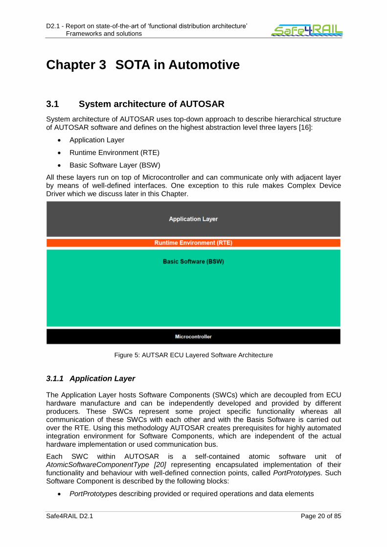
D2.1 - Report on state-of-the-art of ‘functional distribution architecture’ Frameworks and solutions
Safe4RAIL D2.1 Page 20 of 85
Chapter 3 SOTA in Automotive
3.1 System architecture of AUTOSAR
System architecture of AUTOSAR uses top-down approach to describe hierarchical structure of AUTOSAR software and defines on the highest abstraction level three layers [16]:
Application Layer
Runtime Environment (RTE)
Basic Software Layer (BSW)
All these layers run on top of Microcontroller and can communicate only with adjacent layer by means of well-defined interfaces. One exception to this rule makes Complex Device Driver which we discuss later in this Chapter.
Figure 5: AUTSAR ECU Layered Software Architecture
3.1.1 Application Layer
The Application Layer hosts Software Components (SWCs) which are decoupled from ECU hardware manufacture and can be independently developed and provided by different producers. These SWCs represent some project specific functionality whereas all communication of these SWCs with each other and with the Basis Software is carried out over the RTE. Using this methodology AUTOSAR creates prerequisites for highly automated integration environment for Software Components, which are independent of the actual hardware implementation or used communication bus.
Each SWC within AUTOSAR is a self-contained atomic software unit of AtomicSoftwareComponentType [20] representing encapsulated implementation of their functionality and behaviour with well-defined connection points, called PortPrototypes. Such Software Component is described by the following blocks:
PortPrototypes describing provided or required operations and data elements

D2.1 - Report on state-of-the-art of ‘functional distribution architecture’ Frameworks and solutions
Safe4RAIL D2.1 Page 21 of 85
Internal behavior contains requirements regarding the infrastructure (runnables, events, services) and resources needed (data access points, memory)
Implementation describes code, compiler, dependencies as well as memory and CPU resource consumption
3.1.2 Runtime Environment (RTE)
Interaction of application Software Components and/or SWCs to Basic Software Modules within AUTOSAR occur explicitly via the Runtime Environment [26] layer. This abstraction allows Software Components to be independent of specific hardware or software implementation and hence make them interchangeable as long as required interfaces are satisfied. Furthermore, Software Components can be arbitrary distributed over multiple ECUs without any changes in functional or internal implementation of the affected component.
The RTE is application software and specific to the hardware configuration, so it will be individually generated for every ECU Configuration as needed.
3.1.3 Basic Software (BSW)
Decoupling of hardware and software is done in AUTOSAR by the Basic Software Modules [21] further organized in four layers: Services, ECU Abstraction, Microcontroller Abstraction and Complex Drivers.
Services Layer implements abstraction for operating system, communication and memory management. Hardware abstraction takes place in Microcontroller and ECU Abstraction layers whereas special application requirements, which do not fit to the layered AUTOSAR structure, can be implemented in vertical Complex Drivers layer. Complex Drivers are usually used for special purpose functionality like critical timing applications, drivers for devices not specified in AUTOSAR as well as for ECU migration scenarios from proprietary to AUTOSAR architecture.
Figure 6: Basic Software Architecture
Services Layer
ECU Abstraction Layer
Microcontroller Abstraction Layer

D2.1 - Report on state-of-the-art of ‘functional distribution architecture’ Frameworks and solutions
Safe4RAIL D2.1 Page 22 of 85
3.1.4 General Notes
In order to make representation clear and simple, the general AUTOSAR System Architecture shown above is focused on single ECU with single core system, though AUTOSAR is not limited to that and can be adopted for the different application approaches like Multi-Core or Mixed-Criticality Systems discussed in [16].
3.2 Technical characteristics
3.2.1 Configuration and management services
Design and configurations on the System Level lies within AUTOSAR in the responsibility of the vehicle manufacturer. Such design is defined in AUTOSAR System Description File (usually named AUTOSAR_System.arxml) which follows generic paradigms defined by Autosar Top Level Structure [15].
The root of all configuration templates is the meta-class AUTOSAR which can contain multiple arbitrary nested ARPackages. These packages contain PackageableElements which represent particular autonomous entities of AUTOSAR templates, e.g. ARElement. In this way system designer can create arbitrary structures which represent his system and its elements.
3.2.1.1 System Configuration
As one can forebode AUTOSAR allows very flexible configuration and highly distributed development which can in most cases be split over a number of ARPackages and files. On the other hand, such flexibility has to be managed and therefore namespaces are used within AUTOSAR to resolve potential name conflicts [18]. Each ARPackage defines new namespace, hence proper usage of ARPackages is an essential step to minimize risk of name conflicts.
In the real world systems one usually has to deal with a large number of hardware and software derivatives, therefore AUTOSAR configuration supports the concept of Variant Handling (see [15] and [18]) using so called variation points. Each variation point consists of a condition (under which conditions is this variation active?) and a binding time (when should this variation be resolved?).
A binding time defines a classification of processing steps in the AUTOSAR meta-model. Supported binding times are listed in Table 1.
Binding time Description
BlueprintDerivationTime At BlueprintDerivationTime, a model is derived from Blueprints. For example, a function design tool provides the option to derive objects from a predefined set of blueprints [31].
SystemDesignTime SystemDesignTime is characterized by the following tasks:
Designing the Virtual Functional Bus (VFB)
Software Component types (Interfaces)
SWC Prototypes and the Connections between SWC prototypes
Designing the Topology
ECUs and interconnecting Networks

D2.1 - Report on state-of-the-art of ‘functional distribution architecture’ Frameworks and solutions
Safe4RAIL D2.1 Page 23 of 85
Designing the Communication Matrix and Data Mapping
CodeGenerationTime Step at which code is generated. This may be done by hand or using a tool. This step is relevant in cases where the requirements contain variants, but code is only generated for those variants that have been selected, or which need to be resolved later.
PreCompileTime At PreCompileTime, a preprocessor (e.g., the C preprocessor) is used to further customize the code and exclude parts of the code from the compilation process.
There are several reasons for such an exclusion: code is not required for the selected variant(s), code is incompatible with the selected variant(s), or code requires resources that are not present in the selected variant(s). The code that is excluded at this stage code will not be available at later stages.
LinkTime The configuration at this stage determines which modules are included in the resulting object code (executable), and which ones are omitted based on the selected variants.
PostBuild PostBuild is the binding time which is bound latest at startup of the ECU. In other words this is everything between creation of the executable program and startup of the ECU.
Table 1: Binding Times in AUTOSAR Meta Model supported by Variant Handling
Hence using Variation Points and Binding Times it is possible to start with general system design and step by step predefine its derivatives by fixing some of the conditions in variation points.
3.2.1.2 Configuration of ECU Resources
Various resource management methodologies are specified within the AUTOSAR on the low-level ECU configuration. Memory mapping [24] specifies methodologies for code and data mapping to specific memory sections which are necessary to most of ECUs. On the other hand abstraction of the standardized configuration allows flexible integration of SWCs throughout different manufactures hardware and compilers. Memory configuration and management targets following issues usually faced in automotive industry:
Avoidance of waste of RAM
Usage of specific RAM properties
Usage of specific ROM properties
Usage of the same source code of a module for boot loader and application
Support of Memory Protection
Support of partitioning
On the ECU configuration [22] side following resources have to be configured:
Definition of computational cores
Definition of partition for memory and cores to represent virtual ECU modules as OS-Applications
Protection boundaries around groups of software components
Definition of available execution tasks and their assignment to OS-Application or rather ECU partition

D2.1 - Report on state-of-the-art of ‘functional distribution architecture’ Frameworks and solutions
Safe4RAIL D2.1 Page 24 of 85
3.2.1.3 Management Services
AUTOSAR specifies a number of services which have to be configured in order to ensure proper ECU resources, data, process and communication management. These are
Communication Stack (Communications Manager, COM State Manager, Network Manager and Synchronized Time-base Manager)
Non-Volatile RAM Manager
Diagnostic Communications and Event Managers
Function Inhibition Manager
Basic Software Mode Manager
ECU State Manager
Crypto Service Manager
Watchdog Manager. Software Component Template [20] gives a good overview of the necessary configuration process needed.
3.2.2 Inter-partition communication
As discussed in Chapter 3.1, application software is modelled within AUTOSAR as a composition of interconnected components which communicate with each other and with BSW Modules explicitly over interfaces to the RTE. On the other hand RTE is only middle-ware which partially implements so called Virtual Functional Bus in AUTOSAR.
The Virtual Functional Bus (VFB) is the communication mechanism within AUTOSAR that allows individual software components to interact with each other, see [34]. The concept of the VFB allows for a strict separation between application and infrastructure such that software components implementing the application are largely independent of the communication mechanisms through which the component interacts with the other components or with hardware. Moreover, the VFB provides a software architecture oriented view of all the functions the system supports, independent of any ECUs and networks.
The VFB specifies concepts for the following infrastructure-services that are used in automotive applications for implementing component communication:
Communication to other components in the system
Communication to sensors and actuators in the system
Access to standardized services, e.g. read/write to non-volatile RAM
Responding to mode-changes, e.g. changes in the power-status of the local ECU
Interacting with calibration and measurement systems
Figure 7 shows a representation of VFB starting with System Design (top of the graphic) down to realization on hardware (bottom of the graphic). The software components and their virtual connections from the early design step are mapped on the system resources, i.e. ECUs such that these connections between the components are then mapped onto local connections (within a single ECU) or on some network-topology realized by specific communication mechanisms.

D2.1 - Report on state-of-the-art of ‘functional distribution architecture’ Frameworks and solutions
Safe4RAIL D2.1 Page 25 of 85
Figure 7: AUTSAR Virtual Functional Bus: From System Design to Realisation
In order to implement strict separation between application and infrastructure using VFB concepts AUTOSAR defines several structural element like software components with well-defined ports, through which the component interact with the other components. One or several such ports, where each port belongs to exactly one component and represents a point of interaction, represent a communication interface of a component.
AUTOSAR has standardized stable and widely accepted application interfaces to ensure the interoperability of software components from different vendors. The application interfaces aim to cover a wide range of automotive domains.
Body and Comfort
Powertrain
Chassis
Occupant and Pedestrian Safety Systems
HMI, Multimedia and Telematics
There are basically two types of communication available for atomic software components over the VFB, namely: Sender-Receiver and Client-Server communication and three types of data which may be sent are: data, events and modes. Additionally data validity, infrastructure and application error information will be communicated using the concepts of VFB.
3.2.2.1 Sender-Receiver Communication

D2.1 - Report on state-of-the-art of ‘functional distribution architecture’ Frameworks and solutions
Safe4RAIL D2.1 Page 26 of 85
The Sender-Receiver interfaces enables the distribution of information between a sender and some receivers or several senders to a single receiver. Hence AUTOSAR VFB View allows only 1:n or n:1 (with n ≥ 0) communication between sender and receiver for one connection, i.e. this limitation applies only to a single data connection but not to the interface of atomic software component.
Data semantics on the Sender-Receiver interface can be defined as “last-is-best” or “queued” with additional features like initial value, data invalidation or queueing length (see [13] chapter 4.3). Additionally OSEK-COM V3.0.3 data filters are supported which are placed between the sender and the receiver, such that data-element is only passed to the application if the value satisfies filter conditions, otherwise value is rejected (for a queued data-element) or current value of the data-element is not updated (for a last-is-best data-element). VFB also guaranties within the context of one connector that receiver of data-element will always get the newest value in case of last-is-best semantic or that queued data-elements preserve the same order as the order in which the data were produced by one specific sender. On the other hand, VFB does not guarantee any ordering between changes to different data-elements or different connectors, event within the same interface.
3.2.2.2 Client-Server Communication
Client-Server communication represents widely used communication pattern in distributed systems where the server is a provider of a service and the client is a user of a service. Here we call a service some functionality offered by a certain SWC. Client can invoke server calls synchronously, i.e. the client is blocked until either a response from the server has been received, an infrastructure error is returned or the configured maximal blocking time expires, and asynchronously, i.e. the client is not blocked.
AUTOSAR defines a static n:1 client-server mechanism such n≥0 clients can send requests to a server which offers some services made available as operations. Each such operation is associated with typed arguments and return values, which are transported between the client and the server.
The client is allowed for some specific operation to call only one invocation before this operation returns with either a valid value or with an error. However, it is allowed for one client to issue multiple invocations on different operations. In the latter case, the VFB makes no guaranties on the ordering or return values of those invocations.
3.2.2.3 Network Communication
Configuration of Network Communication belongs within AUTOSAR Methodology to the step of the system topology definition. The VFB is refined into a system by defining a topology of ECUs and Networks, deploying software components to the ECUs, and deriving the communication matrices required to interconnect the distributed features.
A detailed description of network communication in AUTOSAR is provided in Safe4RAIL deliverable D1.1 (State-Of-The-Art Document on Drive-by-Data).
3.2.2.4 Service Discovery
Implementation of the Scalable service-Oriented MiddlewarE over IP (SOME/IP) [25] in AUTOSAR allows flexible application of dynamic service discovery, which due to digitalisation increasingly gains importance in automotive.
The AUTOSAR Service Discovery [27] module offers functionality to detect and offer available services – i.e. functional entities – within the vehicle network, see Figure 8. To do so, it makes use of the IP Multicast and so called SOME/IP Service Discovery messages. Hence different ECUs can offer Service Instances and find available Service Instances within
D2.1 - Report on state-of-the-art of ‘functional distribution architecture’ Frameworks and solutions
Safe4RAIL D2.1 Page 27 of 85
the vehicle network. Service Instances are single implementations of a service that is defined by its service interface.
Ethernet topology and SOME/IP implementation in AUTOSAR makes it possible to use not preconfigured switched networks with multiple nodes which can dynamically announce or discontinue services as well as locate them by the clients on request.
Figure 8: Overview of SOME/IP Transformer
3.2.3 Time services
There are basically two time services with their dependent modules specified by AUTOSAR which fulfil specific application requirements, namely: Time Service [29], Synchronized Time-Base Manager [28].
Time Service Module of the BSW Service Layer provides services for time based functionality within the ECU based on the General Purpose Timer (GPT) [23]. There are four predefined timers with predefined physical time unit and a predefined physical range:
Tm_PredefTimer1us16bitType
Tm_PredefTimer1us24bitType
Tm_PredefTimer1us32bitType
Tm_PredefTimer100us32bitType
Services of the module may be used e.g. to measure CPU and task load; for triggering state transition in the state machine based on timing; or to implement timeout supervision of modules.
A more important time service for a distributed functional architecture is the global time synchronisation provided by the BSW module “Synchronized Time-Base Manager” (StbM)
Ethernet

D2.1 - Report on state-of-the-art of ‘functional distribution architecture’ Frameworks and solutions
Safe4RAIL D2.1 Page 28 of 85
[28], such that time bases of multiple nodes of a distributed system are synchronised. AUTOSAR considers two use cases of StbM: synchronisation of runnable entities and provision of absolute time value.
First case is relevant, when e.g. execution an arbitrary number of runnable entities must be started with a well-defined and guaranteed relative offset (relative offset can be equal to 0). Such requirement can be specified by the AUTOSAR Timing Extensions [30] and must be fulfilled independently of actual deployment of the software components.
In case of need for a temporal correlation of signal or event data from different sources; or synchronised access to the calendar time for diagnostic events storage the system should use StbM for a provision of an absolute time value.
As the StbM does not provide any network time protocols or time agreement protocols to synchronise its local time bases to the bases on other nodes, it interacts with the BSW communication modules to handle these protocols. Currently there are time synchronisation modules for the CAN, Ethernet and FlexRay protocols specified within the AUTOSAR.
Figure 9: Network Topology of the Synchronised Time-Base
Figure 9 shows an example of the network topology for synchronised time-bases. Here we see one time domain managed by the global time master which is the owner of a certain time base. Global time master defines network protocol specific time masters (TM) and hence specify some certain time subdomains. Furthermore, these subdomains may have multiple time gateways (TG) containing one time slave (TS) acting as time base recipient and multiple time masters which distribute this time base to sets of time slaves e.g. other time subdomains. Time gateway can be connected to different types of bus systems.
3.2.4 Input/output services

D2.1 - Report on state-of-the-art of ‘functional distribution architecture’ Frameworks and solutions
Safe4RAIL D2.1 Page 29 of 85
AUTOSAR encapsulates all communication between software components and hardware component and basic modules into Sender-Receiver and Client-Server communication interfaces which are then are carried out through the RTE. Hence we refer a reader to chapters 3.1 and 3.2.2 for a detailed description of each interface.
3.2.5 Real-time support
AUTOSAR standard defines as a scope of application among others to be dedicated for real time systems [16]. This goal is formally defined as requirement in main AUTOSAR requirements specification document [17]. Moreover, AUTOSAR aims not only to make the final software be able to run on the real time embedded ECU, but also to support decision and correct implementation of timing requirements (especially for distributed systems) including data and control flow related requirements.
Timing Extensions [30] specification supports constructing embedded real time systems that satisfy given timing requirements and defines methodologies to perform timing analysis and validation [33] of the build systems. Hence, timing specifications supports a top-down design approach, since the constraints defined in the early phase of the project shall be seen as extra functional requirements agreed between development partners.
3.2.6 Fault isolation
In terms of fault isolation, AUTOSAR offers a number of features to ensure that faults do not propagate from a software component to another. These services are provided in the services layer in the Basic Software (BSW). Fault isolation services are provided by means of memory protection, peripherals protection, timing protection, service protection, or protecting the hardware.
In the case of the OS needing to handle the protection, Protection Hooks are provided by the OS for the notification of protection errors at runtime.
3.2.6.1 Memory protection
Self-protection: The Operating System module protects itself (data sections, stacks, and code) from access by OS applications and other applications.
Application protection: furthermore, the OS provides memory protection services in the sense that tasks cannot write to memory (data sections, stacks and code) from other tasks either within the same application or between applications.
If a memory access violation is detected, the OS will trigger a respective error.
3.2.6.2 Peripherals Protection
Access to peripherals by non-trusted applications can be restricted, to write to their assigned peripherals only. This includes reads that have the side effect of writing to a memory location.
3.2.6.3 Timing Protection
For safe and accurate timing protection it is necessary for the operating system to control the expected task times at runtime, for which mechanisms are provided based on the statically configured bounds. These bounds encompass the execution time of task in the system

D2.1 - Report on state-of-the-art of ‘functional distribution architecture’ Frameworks and solutions
Safe4RAIL D2.1 Page 30 of 85
(configurable upper bound), the blocking time due to shared resources or disabling interrupts (configurable upper bound), and the inter-arrival rate of tasks and/or interrupts in the system. On the latter, for example, inter-arrival time enforcement on communication interrupts can be used to protect for “babbling idiot” source of interrupts,
When the timing bounds are violated, an error handling routine is called that ensures that the task is halted and the execution of further tasks within their respective time budget is allowed.
3.2.6.4 Service protection
As OS-Applications can interact with the Operating System module through services, it is essential that the service calls will not corrupt the Operating System module itself. Service Protection guards against such corruption at runtime.
There are a number of cases to consider with Service Protection, i.e.
(1) When an OS-Application makes an API call with an invalid handle, object, address or out of range value.
(2) When a service call is made in the wrong context (3) When a call leaves the system in a state with undefined behaviour that would allow
the OS module to be corrupted through its own service calls. For example, an interrupt routine that ends with locked interrupts or allocated resources
(4) When an OS-Application makes an API call that impacts on the behaviour of every other OS-Application in the system, which must be restricted especially for non-trusted applications. Concretely, the OS will ignore such calls from non-trusted OS-Applications.
(5) When an API call targets to manipulate Operating System objects that belong to another OS-Application (to which it does not have the necessary permissions), e.g.
an OS-Application tries to execute ActivateTask() on a task it does not own.
3.2.6.5 Protecting the Hardware
As the computing core (CPU) hardware provides privileged and non-privileged modes of operation, the system (software platform) will typically be configured for the OS to utilize the operating system module which can use the control registers of the MPU, timer unit(s), interrupt controller, etc. and therefore it is necessary to protect those registers against non-trusted OS-Applications.
3.2.7 Health monitoring
In addition to the OS protection services, AUTOSAR employs the concept of the so-called “Watchdog Manager”. The Watchdog Manager monitors the application flow during run-time and compares the state to pre-configured constraints.
When a violation of such constraint is detected, the Watchdog Manager will trigger corrective action. The Watchdog Manager specification is defined in detail in the AUTOSAR “Specification of Watchdog Manager”.
In order to operate the Watchdog Manager, an application must be modelled with “Checkpoints”. The Watchdog Manager will follow the correctness of transitions from one

D2.1 - Report on state-of-the-art of ‘functional distribution architecture’ Frameworks and solutions
Safe4RAIL D2.1 Page 31 of 85
checkpoint to the next based on timing constraints. The application designer must insert the respective function calls to the Watchdog Manager whenever a checkpoint is reached, so that the execution flow can be monitored. Constraints to the execution flow can be either periodic (e.g. how often has a checkpoint been reached in a certain timeframe) or aperiodic (e.g minimum or maximum bound on the transition from one checkpoint to the next).
Depending on the application, the granularity for setting checkpoints can be coarse or fine-grained. The granularity of Checkpoints is a trade-off between the number of detected failures, configuration complexity and the runtime overheads (because additional checks consume memory and CPU cycles).
Depending on the failure detected, following actions can be configured to be applied by the Watchdog Manager to recover from a failure:
Local Failure Recovery in the Application
Global Failure Recovery in the Application
Partition Restart
Watchdog Reset
Immediate MCU Reset
3.2.8 Security services
The complexity of embedded systems in the automotive domain is increasing due to the merge of the physical and the virtual world. Physical components, such as sensors and actuators, have to offer real-time response at any time and behave in a safe, secure and robust way concerning threats and malicious attacks. In order to guarantee this behaviour, several components of a system with a different criticality have to be partitioned and isolated driven backed by security mechanisms. This strategy prevents one domain from adversely affecting other domains.
Different ECUs (Electronic Control Units) are commonly used within modern vehicles. Since the connectivity is increasing and the car is more and more connected to the external world, such as cloud services, a secure communication between various components has to be guaranteed. Novel features of a car, e.g. (partially/full) automated driving, might attract hacker’s attention and used as an interface for malicious attacks. Therefore, the communication among the car’s ECUs as well as to the external world has to be secured by means of security mechanisms as described in section 2.1.7.2. Cryptographic services and functionalities represent, among others, an integral part of AUTOSAR. In detail, AUTOSAR is using a standardized interface for cryptographic services, such as CSM (Crypto Service Manager) and CAL (Crypto Abstraction Library), in order to provide a secure on-board communication. The main features of AUTOSAR’s cryptographic services are hash calculation, generation and verification of message authentication codes and digital signatures and symmetrical encryption. These features were explained in detail in the deliverable D3.11 of Safe4RAIL.
3.2.9 Requirements for underlying platform
AUTOSAR prescribes no special requirements for the underlying platform which have to be met in order to apply the standard. However in the AUTOSAR sense an ECU means a microcontroller plus peripherals and the corresponding software with its configuration. Hence, each microcontroller requires its own instance of the ECU Configuration (see [18]) since the mechanical design of the ECU is not in the scope of AUTOSAR.

D2.1 - Report on state-of-the-art of ‘functional distribution architecture’ Frameworks and solutions
Safe4RAIL D2.1 Page 32 of 85
3.3 Non-technical characteristics
3.3.1 Example products
AUTOSAR is used in automotive industry in functional components for following systems:
Driver assistance
Driving dynamics for ignition and electric power trains
Safety functions
Comfort functions
Various tool vendors provide support for AUTOSAR technology starting with system design, basis and application software component configuration and integration, and finally ending by runtime environment generators and deployment tools for ECUs.
3.3.2 Relationship to safety standards
AUTOSAR covers many fields of functional safety in automotive. The approach during development of AUTOSAR related to functional safety is comparable to a Safety Element out of Context (SEooC) approach as described in ISO DIS 26262-10, chapter 10. The following list presents safety related fields considered in [32]:
Program Flow Monitoring, i.e. checking the correct execution of software.
Timing Related Features, i.e. observation that the systems actions and reactions are performed within the right time.
E-Gas Monitoring, i.e. by the AKEGAS working group standardized safety requirement e.g. to prevent the hazard of unintended acceleration.
Communication Stack, i.e. safety mechanisms related to communication failures modes.
End-to-End Communication Protection, i.e. data are transmitted using mechanisms to protect them against the effects of faults within the communication link; Implementation of
E2E protection library is adequate for safety-related communication having requirements of ISO 26262 up to Automotive Safety Integrity Level (ASIL) D.
Memory Partitioning and User/Supervisor-Modes, i.e. support for a modular implementation of the embedded systems that consist of both safety-related software components of different ASIL levels or of safety-related and non-safety-related software components.
3.3.3 Business model
AUTOSAR adopted three-tier partnership with the specific rights and duties:
Core Partners
Premium Partners
Associate Partners
These partners may or must cooperate on work packages in AUTOSAR and therefore get access to relevant information and specifications, royalty-free access to AUTOSAR technology and free-of-charge license for automotive applications as well as access to information and the results of the development.
Additionally two supporting roles of partnership are available:
Development Partners
Attendees

D2.1 - Report on state-of-the-art of ‘functional distribution architecture’ Frameworks and solutions
Safe4RAIL D2.1 Page 33 of 85
Detailed information on rights and duties for each of the membership is available at https://www.autosar.org/partners/partnership/types/.
3.3.4 License cost
All Partners except Attendees are allowed to use AUTOSAR technology royalty-free and with a free-of-charge license for automotive applications. Annual contributions for membership are listed on https://www.autosar.org/partners/partnership/types/.
3.3.5 Support for third libraries
In general AUTOSAR does not claim completeness of specification for the whole scope of automotive, rather it foresees integration of non-AUTOSAR components (see Requirements Specification [RS_BRF_02280] in [19]). There are several cases where AUTOSAR considers integration of not specified components:
Integration of non-AUTOSAR software components in AUTOSAR ECU [18]
Interaction of AUTOSAR ECU with non-AUTOSAR ECUs, sensors or actuators [34]
Bypass of BSW modules by implementing Complex Device Drivers [22]
3.3.6 Legal considerations
Membership by AUTOSAR allows usage of technology in automotive domain. Application in roLling stock domain should be evaluated separately.

D2.1 - Report on state-of-the-art of ‘functional distribution architecture’ Frameworks and solutions
Safe4RAIL D2.1 Page 34 of 85
Chapter 4 SOTA in Aerospace
As discussed in the introduction in Chapter 1, Safe4RAIL will create the mixed-criticality application framework concepts for railway architecture. And Safe4RAIL will do so by identifying cross-industry best practices, models of computation and embedded platform technologies to ensure sustainable design of integrated modular architectures and next generation TCMS. Based on the SOTA analysis of domain-specific standards and requirements in the railway domain, the concepts of mixed-criticality application framework will be put forward and proved through implementation in the later work. In this chapter, SOTA of the ARINC 653 in the avionic domain will be analysed in details.
4.1 System architecture of ARINC 653
This section describes the structure of the standard ARINC 653 system.
Figure 10: Standard ARINC 653 System Architecture
The architecture of a standard ARINC 653 system is illustrated in Figure 10 [50]. This architecture attends to separate the application software from the core module, and it achieves to connect the two separated functional parts using Application Executive (APEX) interfaces. The application software layer could include a set of optional system partitions which intend to manage the interactions with specific hardware devices [50]. Every partition can contain one or more processes and every partition (except the system partitions) can only access to the services provided by the APEX interface. The OS kernel provides the execution environment to finish a relevant set of operating system services, such as: (i) process scheduling and management, (ii) time and clock management as well as (iii) inter-process synchronization and communication. We will analyse the framework in detail in the following section.
4.2 Technical characteristics

D2.1 - Report on state-of-the-art of ‘functional distribution architecture’ Frameworks and solutions
Safe4RAIL D2.1 Page 35 of 85
4.2.1 Configuration and management services
Configuration Services
Central to the ARINC 653 philosophy is the concept of partitioning, whereby the applications resident in an integrated module are partitioned with respect to space (memory partitioning) and time (temporal partitioning). Therefore, a partition is a program unit of the application designed to satisfy these partitioning constraints.
Configuration of all partitions throughout the whole system is expected to be under the control of the system integrator and maintained with configuration tables [50]. This configuration table for the module schedule defines the major time frame and describes the order of activation of the partition time windows within it. Easwaran, Arvind, et al. [38] have carried out research about the automatic scheduling techniques of the partitions and processes. And these techniques could be helpful to reduce the system integrator’s work. The following information about each partition is required as a minimum for the system integrator to configure the partitions onto core modules:
1. Memory requirements
2. Period
3. Duration
4. Port attributes
5. Processor core requirements (especially when multiple processor cores are available)
Configuration capabilities supported by the OS should include the assignment of a fixed set of physical processor cores to a partition’s logical cores [50].
Partition management
The following table summarizes what constitutes partition management services, i.e. all services provided by the APEX interface to allow for managing the partitions:
Name Description Availability
GET_PARTITION_STATUS obtain the status of the current partition Normal
SET_PARTITION_MODE
- set the operating mode of the current partition to normal after the application portion of the initialization of the partition is complete.
- setting the partition back to idle (partition shutdown) and to cold start or warm start (partition restart) when a fault is detected and processed
System
Process Management
Within the ARINC 653 standard, a partition comprises one or more processes that are combined dynamically to provide the functions associated with that partition, and all the processes within a partition share the same address space [50]. Regarding the process management, an application requires certain scheduling capabilities from the operating system in order to accurately control the execution of its processes in a manner that satisfies the requirements of the application. A mechanism is also defined to prevent a running process from being pre-empted in order to safely access resources which demand mutually-exclusive access. Access to process management functions is realized via the utilization of APEX services. The OS does not distinguish between two types of processes (periodic/aperiodic). It means that the APEX interface provides the application software with

D2.1 - Report on state-of-the-art of ‘functional distribution architecture’ Frameworks and solutions
Safe4RAIL D2.1 Page 36 of 85
the ability to request schedule of processes on a periodic or aperiodic (e.g., event-driven) basis, and the OS deals with all the requests in the same way.
All the process management services provided by the APEX are listed in the following table:
Name Description Availability
GET_PROCESS_ID Obtain a process identifier by specifying the process name.
Normal
GET_PROCESS_STATUS Get the current status of the specified process which is within the same partition as the requesting process.
System /Normal
CREATE_PROCESS Create a process and return an identifier that denotes the created process.
System
SET_PRIORITY Request to change a process’s current priority.
System
SUSPEND_SELF - Request to suspend the execution of the current process, if it is aperiodic. The process remains suspended until the RESUME service request is issued or the specified timeout value expires.
- Periodic processes cannot be suspended.
System
SUSPEND - Allow the current process to suspend the execution of any aperiodic process except itself. The suspended process remains suspended until resumed by another process.
- Periodic processes cannot be suspended.
System
RESUME - Allow the current process to resume a previously suspended process.
- A periodic process cannot be suspended, so it cannot be resumed.
System
STOP_SELF Allow the current process to stop itself. System
STOP - Make a process ineligible for processor resources until another process issues the START service request.
- This service allows the current process to stop the execution of any process except itself. When a process stops another process that is currently waiting in a process queue, the stopped process is removed from the process queue.
System
START Initialize all attributes of a process to their default values and resets the runtime stack of the process.
System
DELAYED_START - Request to initialize all attributes of a process to their default values, and reset the runtime stack of the process, as well as place the process into the waiting state
- This service allows the current process to start the execution of another process during runtime.
System

D2.1 - Report on state-of-the-art of ‘functional distribution architecture’ Frameworks and solutions
Safe4RAIL D2.1 Page 37 of 85
LOCK_PREEMPTION - Request to acquire the preemption lock mutex created by the O/S within each partition in support of preemption locking.
- Mutex only affects the scheduling of processes within a partition.
System
GET_MY_ID Returns the process identifier of the current process.
System /Normal
Memory management
Every partition has its associated memory spaces which are defined during system configuration and initialization. That means, APEX interface does not need to provide memory allocation services. And all processes of a partition will have access to the same memory spaces of the partition. This includes also processes that are running on different processor cores. If an application uses only ARINC 653 services, then no other action on this part of the application is necessary to maintain memory coherency and consistency of the data transferred through these services. The underlying OS and hardware should be designed to take the maintaining responsibility.
4.2.2 Inter-partition communication
The inter-partition communication definitions contained in the ARINC 653 standard are intended to facilitate communications between ARINC 653 application partitions residing on the same integrated module or on different integrated modules, as well as communication between an ARINC 653 application partition and non-ARINC 653 equipment that is external to the core module of that partition. Messages are used to conduct all the inter-partition communication and sender/receiver of a message are both partitions, not a process within a partition.
The basic mechanism for linking partitions by messages is via channels which provide partitions well defined access points that are called ports (queuing port and sampling port). The channel describes a route connecting one sending port to one or several receiving ports. The system integrator (NOT the application developer) configures the channel connections within an integrated module and the channel connections between an integrated module and components external to the integrated module. It is the system integrator’s responsibility to ensure that the different nodes crossed by each channel are consistently configured. The consequence is that the source, destinations, mode of transfer, and unique characteristics of each channel cannot be changed at run-time.
ARINC 653 communication is based on the principle of transport mechanism independence at partition level. That means, the underlying transport mechanism transmits the messages and ensures that the messages leave the source port and reach the destination ports in the same order. Communication is location transparent and independent of the underlying transport mechanism. Any manipulations of the messages under the ARINC 653 interface are invisible to the applications. Applications regard the messages as atomic entities and take the responsibilities to assure the data meets the applications’ requirements through e.g. range checks etc. The application designer and system integrator cooperate with each other in order to ensure the chosen transport mechanism to meet the message transport latency and reliability requirements of the applications.
The sampling port services are listed in the following table:
Name Description Availability
CREATE_SAMPLING_PORT Create a sampling port. System

D2.1 - Report on state-of-the-art of ‘functional distribution architecture’ Frameworks and solutions
Safe4RAIL D2.1 Page 38 of 85
WRITE_SAMPLING_MESSAGE
Write a message in the specified sampling port. The message overwrites the previous one.
System
READ_SAMPLING_MESSAGE - Read a message from the specified sampling port.
- A validity output parameter indicates whether the age of the read message is consistent with the required refresh period attribute of the port.
System
GET_SAMPLING_PORT_ID Request the sampling port identifier that corresponds to a sampling port name.
System /Normal
GET_SAMPLING_PORT_STATUS Return the current status of the specified sampling port.
Normal
The queuing port services are listed in the following table:
Name Description Constrains
CREATE_QUEUING_PORT Create a port of communication operating in queuing mode. An identifier is assigned by the O/S and returned to the calling process.
System
SEND_QUEUING_MESSAGE Send a message in the specified queuing port.
System
RECEIVE_QUEUING_MESSAGE Receive a message from the specified queuing port.
System
GET_QUEUING_PORT_ID Request the queuing port identifier that corresponds to a queuing port name.
System /Normal
GET_QUEUING_PORT_STATUS Request the current status of the specified queuing port.
Normal
CLEAR_QUEUING_PORT Discard any messages in the specified port’s receive queue.
System
APEX inter-partition communication has the following limitations:
1. The performance and integrity of inter-partition communications is dependent on the underlying transport mechanism, which is beyond the scope of this standard. It is assumed that the underlying transport mechanism supports the defined port services of the APEX interface.
2. Although data abstraction should assure parameter consistency, equivalent performance between differing transport mechanisms is not guaranteed.
3. Synchronous behaviour between communication ports is not guaranteed by the APEX interface.
4. The OS should ensure that the messages provided by the application are delivered to the application in the same order.
5. Any particular messages can only originate from a single source.
6. When a recipient accesses a new instance of a message, it can no longer request access to an earlier instance. It cannot be assumed that the OS will save old versions of messages.

D2.1 - Report on state-of-the-art of ‘functional distribution architecture’ Frameworks and solutions
Safe4RAIL D2.1 Page 39 of 85
7. The OS does not ensure that the channels connected to the ports have been entirely initialized when they are used at the first time. Because channels may cross different nodes and these nodes may not necessarily be initialized simultaneously.
Inter-partition communication conducted externally across core module boundaries should conform to the appropriate message protocol. The message protocol to be used for this communication is system specific.
Each individual port may be configured to operate in either sampling mode or queuing mode. Messages sent by a port are routed to one or more other ports of the module in the sampling mode. Otherwise they are routed to only one other port of the integrated module in the queuing mode.
4.2.3 Time services
For the ARINC 653 standard [35], time is unique and independent of partition execution within an integrated module. All time values or capacities are related to this unique time and are not relative to any partition execution. Specifically, the OS should provide time-outs for intra-partition and inter-partition communication in order to manage time. Every process is associated with a time capacity to represent time restrictions of a process to satisfy its processing requirements. When a process is started, its deadline is set to the value of current time plus its time capacity. This deadline may be postponed by means of the REPLENISH service from the APEX interface. A process’s time capacity is an absolute duration of time instead of an execution time. This means that a process deadline overrun will occur even when a process is not running inside or outside the partition time window, but missing a deadline will be acted upon only inside a partition time window of its own partition. Time replenishment should be carried out to ensure that a deadline miss will always be handled.
According to the ARINC 653 standard [35], partition timing interrupt generation should be deterministic and time partitioning should not be disturbed by the use of interrupts. However, temporal partitioning is influenced by the OS overhead. Inter-module communications acknowledgements and time-out interrupts may interrupt one partition even though the events relate to a different partition. As a result, the time duration allocated for use by an application may be impacted.
Within ARINC 653, the following time services are defined:
Name Description Availability
TIME_WAIT Request to suspend execution of the requesting process for a minimum amount of elapsed time. A delay time of zero allows round-robin scheduling of processes of the same priority.
System
PERIODIC_WAIT
Request to suspend execution of the requesting periodic process until the next release point in the processor time line that corresponds to the period of the process.
System
GET_TIME Request the current value of the system clock. The system clock is the value of a clock common to all partitions in the core module.
System /Normal
REPLENISH - Request to update the deadline of the current process with a specified BUDGET_TIME value.
- A periodic process’ deadline cannot be postponed past its next release point.
System

D2.1 - Report on state-of-the-art of ‘functional distribution architecture’ Frameworks and solutions
Safe4RAIL D2.1 Page 40 of 85
4.2.4 Input/output services
In the ARINC 653 standard, the OS takes the duty to restrict access to I/O for each individual partition. While ARINC 653 clearly defines operations and interfaces for inter-partition I/O via ARINC sampling or queuing ports, I/O to physical devices or inter-module I/O are left to RTOS implementers and other stakeholders to provide [43]. As discussed in 4.2.3, using of interrupts can cause temporal violations in the IMA system due to their asynchronous nature. I/O solutions towards this problem could be as following [43]:
1. Polling-mode software operation;
2. Hardware-based design which removes the interrupt activity from the primary CPU bus;
3. Single partition-based I/O implementation.
The polling–mode solution clearly introduces a limit to the bandwidth of the I/O data that may be processed and also increases the latency of response. For this reason, it needs to be analysed for performance before implementation.
In another way, using of a separate bus to deal with interrupts can eliminate the possibility of temporal interactions due to interrupts. However, it still presents a problem of added complexity as well as additional hardware requirements. Such a method to provide the I/O data to the application(s) which require(s) access to the resource is still required when using the hardware-based solution. From this point of view, problems caused by I/O interrupts are not totally solved.
Single partition-based I/O implementation is a classic choice for a partitioned system, although it also has significant drawbacks. The I/O bandwidth will be limited by the frequency at which the I/O partition is scheduled in the major time frame. Another significant problem is that the necessary periodicity of the I/O partition can be too high to be accommodated by the overall system schedule. Furthermore, sharing of devices by multiple partition-based applications can create a situation of data mixing in the I/O devices.
4.2.5 Real-time support
In ARINC 653 standard [35], the scheduling of partitions is strictly deterministic over time and the module schedule is fixed for particular configuration of partitions within an integrated module. This mechanism is invented to support the real time characteristics of the system.
All the constituent processes within a partition can be scheduled to operate concurrently in order to achieve their real-time requirements. The premise is that a partition has been allocated more than one processors. Although processes within the same partition can be pre-empted based on their priorities, LOCK-PREEMPTION and UNLOCK-PREEMPTION services are provided by the APEX to guarantee that a process can avoid being pre-empted by the other processes. In this way, ARINC 653 can guarantee implicitly real-time services in required situations.
However, temporal partitioning is influenced by the OS overhead. Inter-module communication acknowledgements and time-outs may interrupt one partition even though the events relate to a different partition. As a result, the time duration allocated for use by an application may be impacted. This may cause the delay of the supported output.
4.2.6 Fault isolation
Trying to create provably correct software may be very expensive in complex systems, and the fault isolation depends on RTOS architecture with a help of on-chip hardware mechanisms used to safely host such functional software on one or many CPU cores.

D2.1 - Report on state-of-the-art of ‘functional distribution architecture’ Frameworks and solutions
Safe4RAIL D2.1 Page 41 of 85
Safety-related properties and high availability require robustness against erroneous inputs, independence or freedom from interference between different functionalities, fault tolerance capabilities and the ability to maintain the integrity of all the data in the system or application memory. The mechanisms which support fault isolation must be built into the RTOS and typically utilize HW-based mechanisms in SoC / MCU. This can help to detect (and handle) programming or configuration errors, before they lead to a system failure.
Fault isolation is accomplished by temporal and spatial separation of access to any computing, networking, storage/memory, IO resources and platform services. Fault isolation prevents any unintended effects on other functions deterministic performance, latency/jitter, sampling rate or resource reservation.
In an integrated architecture this can be accomplished by:
the platform design (layering/partitioning) and isolation mechanisms
appropriate elementary isolation mechanisms implemented in HW
complementary and supporting mechanisms implemented in RTOS software architecture
qualified, verified and validated system, unit and SW module configuration
error handling: appropriate reaction on emerging fault, and approaches to prevent any further fault propagation
If all of those aspects are appropriately implemented, integrated, verified and validated there should be no unintended interference among functions hosted in different partitions, possibly with different QoS or safety requirements and criticality.
In support of fault isolation, health monitoring function can capture different module, process and partition errors and initiate recovery activities or shutdown based on the system configuration.
4.2.6.1 Fault isolation for partitioning RTOS software platforms
In order to ensure fault isolation between partitions, it is required to offer elementary isolation mechanisms:
space-partitioning which ensures that no process can modify the memory or data of another process without authorization
Time partitioning which ensures that a processing within a given time budget cannot be affected by the actions of any other task from other partitions.
The simplest approach to time-partitioning is static scheduling of partitions. A partitioning OS typically supports a static table-driven scheduling approach with table-driven initiation of tasks and resource accesses. This approach is well suited for safety-critical, hard real-time systems for which the system operation and temporal performance is defined at design time, not at runtime.
In ARINC653, the resources used by each partition are specified at system build time. The corresponding objects (communication channels, queues, events...) are created during initialization phase of this operational mode, and then the time-partitions enter normal operating mode.
Within a partition, a specific partitioning RTOS can be executed, which can rate-monotonically schedule different tasks, or use some other scheduling scheme. The objective is that within a partitioning period, only one application gets all the resources and does not influence any other more or less critical applications. Even if an interrupt is initiated, it shall not change time budget calculations for a partition.

D2.1 - Report on state-of-the-art of ‘functional distribution architecture’ Frameworks and solutions
Safe4RAIL D2.1 Page 42 of 85
The combination of space and time partitioning makes it possible for applications of different criticalities to run on the same platform at the same time, while ensuring that lower-rated criticality applications do not interfere with the operation of high-criticality applications [42].
4.2.6.1.1 MCU/SoC hardware support for time partitioning
Privileged mode
There must be a clear separation between RTOS activities and application activities. Separated supervisor or user modes associated with an appropriate RTOS architecture may prevent any unintended interactions and define formal boundaries between application code and the system code.
It is important to have the possibility to execute some instructions or access certain variables only in the supervisory mode. A status register/field handling is required to switch among partitions and control assignments.
Cache memory
Cache memory is a hardware architecture mechanism used to improve performance of applications running on the target processor. As the L1/L2 cache memory is common to all partitions, the use of this resource requires careful analysis. The impact of cache memory can spread into time and space partitioning dimension.
If the complexity or available information on cache do not allow exact analysis, after every time-partition is completed, its stacks, relevant variables and partition status data shall be stored, while the CPU caches should be flushed/cleaned up, so that the next partition can start from a clean initial point.
Partitioning and context switching can be computationally costly. A configurable variety of cache write/reads is required to optimize cache and ensure that IO and data can be accessed. The simplest approach for certification is to inhibit cache use, or to use MCUs with tightly-coupled zero cycle memories and avoid cache use.
Interrupts and control of asynchronous events
Another important point are interrupts and exceptions, and HW support for their processing on MCU. The CPU should have the capability to pre-empt any IRQs and then forward to target applications.
The fault isolation in this case is a blend of configuration and other resource controlling/monitoring mechanisms such as external interrupts from monitors, watch-dogs and similar devices, which are essential for health monitoring and diagnostics. In such cases depending on urgency the processing can occur at RTOS level and stops normal time-partitioning operation. Exact implementation approach can vary from platform to platform, but it must offer a convincing safety case and evidence for certification authorities.
Relevant incoming interrupt source, context and timing shall be identified, and the maximum interrupt handling budget and delay shall be assessed. Within the interrupt vector handling routine, the forwarding of the interrupt must reach the right partition.
The time budget shall not exceed the maximum time partition duration when executed with all other interrupts and application tasks within the partition.
Time interrupts are important in strictly deterministic architectures with synchronous networking, and under normal conditions, a partition will receive a set of dedicated time-interrupts within the partition execution time.

D2.1 - Report on state-of-the-art of ‘functional distribution architecture’ Frameworks and solutions
Safe4RAIL D2.1 Page 43 of 85
ARINC653 preference for IO recommends is polling as the logic behind initial work was a cyclical execution model without any synchronization to external time sources.
In case we have a system synchronization source, time-driven interrupts can also drive the hosting of IO operation if their operation is scheduled to external time source and if the partitions are synchronized.
Other issues
Pipeline throughput optimization mechanisms enable the out-of-order execution and parallelization, which can lead to much more complex verification, but also lead to timing creep or other unintended interactions during the partition or task switching. It is important to be able to disable any extensive pipeline throughput optimization. Therefore the majority of safety-critical software is compiled without any pipeline-related optimizations which can have dynamic effects.
4.2.6.1.2 MCU/SoC hardware support for memory management and space partitioning
Memory management allocates computer memory to a defined partition and its tasks. RTOS shall undertake all activities to prevent unintended interactions. Memory management unit (MMU) on the chip or SoC allows robust management and virtualized access to memory areas dedicated to specific partitions. Alternatively, simpler mechanisms such as memory protection unit (MPU) can be used. MMU slows down the access to memory, so for less powerful MCU / SoC cores, MMU can be a better option if it is required to extract more processing power per core and related costs.
Furthermore it makes sense to use mechanisms which separate code (read-only) from data, or use build-in memory banks, and avoid even remote possibility that application data overwrite code within one partition.
For fault isolation, it is essential to plan resources in advance and leave enough memory for future extensions, and make the static assignment of memory to avoid hard-to-verify complex algorithms for dynamic allocation. Memory space shall be completely isolated within partition.
4.2.6.1.3 Time- and space partitioning via execution on distributed resources
In time-synchronous architectures it is possible to design a distributed computer as a set of of distributed resources hosting time-synchronized partitions. Even with ARINC653 it is possible to have a system-level time partitioning, in addition to the physical spatial separation of resources on different computers connected by a network.
4.2.7 Health monitoring
Health monitoring is a part of the ARINC 653 standard. The specification identifies a number of error codes that must be detected and handled. An error can be handled within a process, in a partition, or in the health monitoring module. Health monitoring code can be used to contain the errors, to substitute alternate actions, or simply to record the errors in an error log.
The health information relevant for time-partitions is collected in the health monitoring RTOS function. This function is responsible for monitoring and reporting hardware, application and O/S software faults and failures. The health monitoring helps to identify faults and can thus initiate actions to contain them. Fault response corresponds to a safe state for the aircraft or for the system.

D2.1 - Report on state-of-the-art of ‘functional distribution architecture’ Frameworks and solutions
Safe4RAIL D2.1 Page 44 of 85
Health monitoring will take into account different error sources, log them and determine recovery actions configured by the system designer.
Module level errors are:
Module configuration error during module initialization
Other errors during module initialization
Errors during system function execution
Errors during partition switching
Power fail
Partition level errors:
Partition configuration error during partition initialization
Partition initialization error
Errors during process management
Errors during error handler process
Process level errors:
Application error raised by an application process
Illegal O/S request
Process execution errors (Overflow, Memory violation...)
Depending on RTOS, CPU architecture, system configuration, operational state and ARINC653 implementation, different faults will be detected and recovered, based on configuration of the health monitoring function, provided by the system integrator.
For each partition there is a configuration table with an appropriate preconfigured response on different fault classes. The recovery actions could be to restart the partition (cold or warm) or stop the partition (idle) in response to a fatal fault (e.g. power failure or memory integrity breach).
4.2.8 Security services
Basically, embedded systems in aviation are composed of software components installed on hardware elements. Therefore, software components have to fulfil the Reliability, Availability, Maintainability and Safety (RAMS) objectives during design- and development-phase as well as in active operating mode.
Applications at different criticality levels in aviation require an isolated execution in order to run multiple applications on the same hardware platform. To be more accurate, applications with a high criticality level like autopilot have to be isolated from low-critical systems, such as the in-flight entertainment system, in order to prevent adversely affects. This isolated system design allows separating critical components from non-critical, while running them on the same processor. The isolation guarantees that the behaviours of the non-critical component will not disrupt the critical components in the system. Such isolation in the aviation domain is achieved by means of the ARLX (ARINC 653 Real-time Linux on Xen) hypervisor developed by DornerWorks [51]. ARLX is originally based on the open-source Xen hypervisor and provides therefore the flexibility of combining further open-source-licensed tools with high level security and safety in embedded engineering. Besides the hypervisor-mode of the ARLX running multiple virtual machines in an isolated state, the ARLX is also able to be implemented and executed as an operating system due to the underlying open industry standard ARINC 653 [48].

D2.1 - Report on state-of-the-art of ‘functional distribution architecture’ Frameworks and solutions
Safe4RAIL D2.1 Page 45 of 85
4.2.9 Requirements for underlying platform
In the ARINC 653 standard [35], in order to isolate multiple partitions in a shared resource environment, the hardware should provide the OS with the ability to restrict memory spaces, processing time, and access to I/O for each individual partition [50]. Partition timing interrupt generation should be deterministic. And any interrupts required by the hardware should be serviced by the O/S. At the same time, interrupts are strictly forbidden to disturb the time partitioning.
Specific requirements are clearly put forward for the processors [50]:
1. The processing capacity should be sufficient to meet the worst-case timing requirements;
2. The processor can access to required I/O and memory resources;
3. The processor has access to time resources to implement the time services;
4. The processor provides a mechanism to transfer control to the OS if the partition attempts to perform an invalid operation;
5. The processor provides atomic operations for implementing processing control constructs. These atomic operations will induce some jitter on time slicing. Furthermore, atomic operations are expected to have minimal effect on scheduling.
ARINC 653 supports for the services to be utilized with a core module which can contain more than one processor cores. This standard only defines use of multiple processes within a partition scheduled to execute concurrently on different processor cores. Definition of scheduling behaviours associated with multiple partitions scheduled to execute concurrently on different processor cores is still an open issue.
4.3 Non-technical characteristics
4.3.1 Example products
4.3.1.1 RTOS
A Real-Time Operating System (RTOS) manages logical responses to application demands as well as allocates processing time, communication channels and memory resource to applications. In the following subsections we discuss about the popular existing COTS RTOS frameworks in detail, which are ARINC 653 compliant or can be adjusted to provide ARINC 653 API.
VxWorks 653
For the time partitioning aspect, VxWorks 653 [44] is totally compliant with the ARINC 653 standard. VxWorks 653 also provides an option for priority pre-emptive scheduling of partitions. This method permits slack stealing by allowing designated partitions to consume what would otherwise be idle time in the defined ARINC schedule, in order to raise the processor use rate.
Wind River’s VxWorks 653 [44] provides the system’s integrator capabilities to limit the number of concurrent blocking APEX calls at compile-time. This is done by the static configuration of the number of kernel worker threads which are used to deal with the APEX calls. The configuration data is separate from the partition and its application, so changes can be isolated and rebuilt without altering the partition application itself. This

D2.1 - Report on state-of-the-art of ‘functional distribution architecture’ Frameworks and solutions
Safe4RAIL D2.1 Page 46 of 85
significantly reduces the cost of changes and makes the framework more flexible, which can be useful to achieve the reconfiguration requirements of TCMS framework.
PikeOS
The PikeOS partition scheduler [49] uses a combination of priority and time-driven scheduling. Like in the ARINC 653 standard, threads are grouped into time partitions which are in turn activated by a strictly time-driven scheduler. However, in contrast to the standard, one more time partition exists that is active at all times. This time partition is referred to as the background partition, o/0, whereas the currently active one of the time-switched partitions is called the foreground partition, o/i (i = 1 ... N). In addition to their time partition, threads also have a priority attribute. Whenever both the foreground and background partitions have active threads, the thread to be executed is selected according to its priority.
In this way, priority ranges can be defined, within which the CPU is switched between VMs according to a fixed, strictly time-driven schedule as defined by the ARINC 653 standard. This guarantees that VMs (like partitions in ARINC 653) will periodically receive their time slices. Whenever one of these VMs completes its job prior to having consumed its entire time slice, the unused time automatically falls back to the next lower priority thread in the background time partition. This mechanism can be used to utilize the free time slices of every partition time window. This idea can be useful for the design of the TCMS framework.
LynxOS-178
LynxOS-178 [44] is another ARINC 653 compliant RTOS which is used for some of the Galileo ground segment elements.
The scheduler of LynxOS is pre-emptive and priority based. Which means the current process is pre-empted as soon as a higher priority thread is ready to run. Round-robin, Quantum and FIFO will be used to deal with the situation that the processes have the same priority. Quantum is very similar to round-robin. The only difference is that the length of the time-slice is not fixed, but it is a variable for each priority level.
The LynxOS scheduler [52] schedules both user and kernel tasks together. The kernel tasks are called kernel threads. Kernel threads usually are handlers of different device drivers and their interrupts. Interrupts are assigned the highest priority to ensure that they will be handled at first to guarantee the responsive real-time system. The priority of kernel threads could be dynamically changed to avoid blocking issues. LynxOS relies on semaphores to ensure the synchronization which may lead to the so called priority inversion. Which may be solved by priority inheritance. Using more semaphores can cause deadlocks, hence LynxOS relies on the fact that semaphores are always accessed in the same order in all processes. As long as the software is correctly written, the system will work without errors.
By comparison to the VxWorks 653, the only major difference between the two system scheduling methods seems to be dynamic time-slicing in LynxOS. VxWorks does not use this technique.
XtratuM
XtratuM [36] has been specifically designed for critical real-time systems following the requirements for secure space applications based on the ARINC-653 standard. XtratuM provides ARINC 653 scheduling policy, partition management, inter-partition

D2.1 - Report on state-of-the-art of ‘functional distribution architecture’ Frameworks and solutions
Safe4RAIL D2.1 Page 47 of 85
communications, health monitoring, logbooks, traces, and other services. These can easily be adapted to the ARINC 653 standard. However, it does not provide a compliant API with ARINC 653 standard.
XtratuM is a hypervisor running directly on the native hardware and uses the para-virtualization. Most importantly, XtratuM was designed to meet safety critical real-time requirements, because it provides strong temporal isolation through fixed cyclic scheduler, as well as strong spatial isolation that all partitions don’t share memory at all. Sampling ports and queuing ports are adopted to provide robust communication mechanism. The features meet the requirements of the TCMS framework and mechanisms of XtratuM may be adapted to define this framework. But more flexibility can be provided (e.g. in time scheduling) to raise the resource utilization.
4.3.1.2 Hypervisor
Hypervisors are used to host different kinds of virtual machines (VM). Furthermore, they trap all the instructions of the VMs that need to be emulated as well as cyclically switch the physical machine between different contexts of the VMs.
Virtual machines and partitions in ARINC 653 are similar concepts. Both split a physical machine’s resources into disjunctive subsets. And they enforce safe and secure isolation between software running on these resource subsets. In contrast to partitions, VMs normally host complete OSes along with their world of applications. The underlying hypervisor does not offer any OS services whereas a partitioning OS may or may not do so. Thus, virtualization can be regarded as a special form of partitioning.
4.3.1.3 ARINC 653 simulator
In addition to the existing RTOSes, there already exist a number of simulation approaches. One example is AMOBA which is a simulator that implements the ARINC 653 standard on top of the POSIX. AMOBA aims to provide a portable method of simulating the response of IMA applications to partitioning of CPU, memory and I/O. POSIX is a common programming interface on modern OS. This property of POSIX enables the ARINC 653 simulator and the RTOS to be developed independently.
4.3.2 Relationship to safety standards
ARINC 653 is designed to host applications of different DO-178B levels (from A to E). For the TCMS framework, it should satisfy the IEC 61508 safety standard, from safety integrity level 1 to 4.

D2.1 - Report on state-of-the-art of ‘functional distribution architecture’ Frameworks and solutions
Safe4RAIL D2.1 Page 48 of 85
Chapter 5 SOTA in Railway
5.1 System architecture of TCMS
The Train Control and Management System (TCMS) is a train-borne distributed control system. It provides a single point of monitoring and controlling of all sub-systems of the train.
TCMS comprises computer devices and software, human machine interfaces, digital and analogue input/output capability and the data networks to connect all these. The data networks constitute train communication network (TCN) standardized by IEC 61375 series [9]. The TCN is determinative for the architecture of the TCMS.
5.1.1 Train Communication Network (TCN)
A train is composed of consists. Each consist contains a Consist Network, which is connected via a Train Backbone Node (TBN) to the Train Backbone, which provides the communication infrastructure for the train wide communication. Train Backbone, Consist Network, TBN are the basic components of the train communication network (TCN) according to IEC 61375 series. They are shown in Figure 11, the key terms of the TCN are listed in Table 2.
Figure 11: Basic architecture of the TCN
Term Definition
train composition of one or a set of consists, which can be operated as an autonomous unit, e.g. containing drives and at least one driver’s cab
consist single vehicle or a group of vehicles which are not separated during normal operation, and which contains no, one or several consist networks
train communication network
data communication network for connecting programmable electronic equipment on-board rail vehicles
train backbone communication network interconnecting communication devices in one consist
train backbone node
device connected to the train backbone. A train backbone node can be used to connect end devices or consist networks to the train backbone
consist switch network component used in consist network based on switched technology (ECN)

D2.1 - Report on state-of-the-art of ‘functional distribution architecture’ Frameworks and solutions
Safe4RAIL D2.1 Page 49 of 85
end device unit connected to one consist network or to one set of consist networks prepared for redundancy reasons
Table 2: Key terms in the TCN (IEC 61375 series)
The end devices connected to the TCN may represent for instance:
Intelligent devices, as VCU (Vehicle Control Unit) or DDU (Driver Display Unit), which are not dedicated to a specific train subsystem
Controllers of intelligent subsystems (e.g. traction control, brake control, HVAC)
Remote I/O units, which connect to the TCMS those parts of the train technology which is not handled by a dedicated controller (e.g. controls and indicators on driver desk)
The architecture of the TCN is defined as a hierarchy of two network levels, a train backbone level and a consist network level, as shown in Figure 11. The selection of the two-level architecture was guided by the following requirements:
The communication network which is set-up by the consist network is a static, preconfigured network, whereas the train backbone is a dynamic network, which changes its topology each time there is a change in the train composition. Communication between train backbone nodes may be interrupted if a reconfiguration of the train backbone happens. During times of unavailability of the train backbone communication the consist network communication shall not be affected.
A break-down of a consist network (e.g. due to power loss in the consist) shall not affect the communication between other consists of the same train.
Only the data traffic directed to other consists shall be transported over the train backbone. Intra-consist data traffic shall be kept local to the consist. That is, the train backbone shall not be loaded with all the data traffic in a train.
Two classes of network technologies can be used, either solely or in combination, to set up the train communication network – bus technology and switched technology. The Table 3 lists the networks according to the technology class specified by IEC 61375 series. The Ethernet networks are IP-based networks.
Technology class
Train Backbone Consist Network
bus WTB – Wire Train Bus MVB – Multifunction Vehicle Bus CAN – Controller Area Network (with CANopen application protocol)
switched ETB – Ethernet Train Backbone ECN – Ethernet Consist Network
Table 3: TCN networks according to the technology class
The WTB [39] has the following parameters: bitrate – 1 Mb/s, max. length - 860 m, max. TBNs connected – 32, max. vehicles – 22.
The ETB [12] has the following parameters: bitrate – 100 Mb/s, max. TBNs connected in a train/a consist – 64/32, max. vehicles per consist – 32, max. length of ETB segment (between two TBNs) – 100m, repeaters to extend the range can be used. The lengthening of the ETB segment due to inactive TBN (it is bridged by relays) must be taken into account.
The TRDP (Train Real-time Data Protocol) [10] has been defined as application protocol on ETB by IEC 61375. It covers process data (PD) and message data (MD) exchange. The use

D2.1 - Report on state-of-the-art of ‘functional distribution architecture’ Frameworks and solutions
Safe4RAIL D2.1 Page 50 of 85
of the TRDP on ECN is not mandatory. Instead, the protocols as PROFINET, CIP, IPTCom can be used. If the communicating end devices are located in different consists, i.e. they communicate over train backbone, it is advantageous to use the TRDP also on ECN. In such a case the TBN serves as a router, otherwise it must be implemented as an application gateway.
It can be assumed that with the current new edition of the IEC 61375, which specified the ETB/ECN network, the customers will start to give preference to this type of TCN. The example of ETB/ECN network with the ECN of ring topology and the MVB in the lowest level in one consist is shown in Figure 12.
Figure 12: Ethernet based TCMS architecture
5.1.1.1 Train inauguration
The Train Backbone has to cope with the dynamic nature of the train composition. The number and type of consists in a composition can change during operation – trains can be lengthened or shortened (coupled, uncoupled), the consists can be inserted (the TBN of the consist in the middle is activated later than its neighbours) or missed (e.g. due to a TBN failure). Also, when the driver’s cab on the opposite end of the train has become an active cab the train direction (forward, backward) and orientation (right, left) change. The relative directions and orientations of consists and vehicles in respect to that train direction/orientation (same, inverse) change consequently. This means that all direction/orientation significant information on the train level (e.g. driver’s command “open left door”) must be translated on the consist level with respect to consist’s relative direction/orientation and vice versa.
The information about the current train topology (the sequence of all TBNs, directions and orientations) supplemented with user defined data which describe the properties and functions of the individual consists in the composition are contained in the Train Topology Database (TTDB), which is the output of train inauguration procedure. The train inauguration procedure is executed in all active train backbone nodes, i.e. each TBN has an instance of TTDB. Here the TTDB is locally accessible for all interested devices (network devices and end devices) in the consist by means of a set of management services. The inauguration

D2.1 - Report on state-of-the-art of ‘functional distribution architecture’ Frameworks and solutions
Safe4RAIL D2.1 Page 51 of 85
protocol depends on the technology of the train backbone, i.e. it is different for ETB and WTB.
The inauguration function must ensure the correctness of TTDB in all situations that can occur during train operation. In case of safety-related communication over train backbone it can be determined as safety-related function.
5.1.2 TCMS as a function domain
All train functions are collected in CENELEC EN15380-4 standard [4]. In the Roll2Rail project these functions were classified into the following three function domains:
TCMS – it includes all train control and monitoring functions, both safety-related and non safety-related functions are considered
OMTS (On-board Monitoring and Telematics Services) – it includes all auxiliary services for proper train operation
COS (Customer Oriented Services) – passengers’ Wi-Fi access and Info portal can be considered here.
The Function Domains are shown in Figure 13. The communication in TCMS and OMTS function domain follows IEC 61375 series, communications inside COS function domain are standardized by many different standards. The OMTS function domain, or both OMTS and TCMS individually can be connected to a ground system by MSG device (Mobile Communication Gateway), which is (will be in a near future) standardized by IEC 61375 series. The allocation of function/systems to the individual function domains is given in Table 4.
Figure 13: Function Domains

D2.1 - Report on state-of-the-art of ‘functional distribution architecture’ Frameworks and solutions
Safe4RAIL D2.1 Page 52 of 85
Functions/Systems of a Function Domain
TCMS OMTS COS
Main Control
Train Radio
Air Conditioning
Propulsion
Brakes
Electricity
Lavatories
Lighting
Supporting Systems
Passenger Announcement
System
External Doors and Internal
Doors
ETCS (European Train
Control System)
ATP (Automatic Train
Protection)
ODDRS (Onboard Driving
Data Recording System) acc.
to IEC/EN62625.
Passenger Alarm System
Automatic Announcements.
CCTV.
Infotainment in train embedded
devices
Mobile Phone Amplifiers.
Automatic Passenger Counting.
Vehicle Positioning.
Fare Management or Ticketing.
Driver Assistance System.
E-schedule.
Diagnostics and CBM (condition
based maintenance) systems
Passenger Information System (PIS).
Access for the passenger's
devices (e.g. Wi-Fi access
points)
Access to the public Internet
Passenger Infoportal.
Table 4: Allocation of functions/systems to Function Domains
5.1.3 The architecture of train distributed applications
The TCMS applications (functions in the terminology of TCN) for remote control (e.g. Door Control, Traction Control, Brake Control), which means the control over the whole train, are distributed functions. Figure 14 shows the components of a generic remote control function and as an example the decomposition of the specific function Door Control.
According to [11] the generic remote control function is composed of:
A Function Leader which is responsible to control the function by stimulation of the Function Followers (commands) and to receive the reactions from the Function Followers (status). These interactions and data formats are standardized. The Function Leader is interfaced to TCMS to receive commands and provide status information. This interface is not standardized.
The Train Door Control Unit (DCU) is the Function Leader, which is the controlling part for all doors in the train.
One or more Function Follower(s), at most one per consist network, which is responsible to receive the commands from the Function Leader and to stimulate the Function Devices. The received reactions from the Function Devices are cumulated

D2.1 - Report on state-of-the-art of ‘functional distribution architecture’ Frameworks and solutions
Safe4RAIL D2.1 Page 53 of 85
by the Function Follower and provided as function status of the consist to the Function Leader. The interface to Function Devices is not standardized. The Function Follower must translate the information from standardized interface to Function Leader to that on specific interface to Function Device and vice versa.
The Consist DCU is the Function Follower, which is the agent for one consist (network).
One or more Function Device(s), which are receiving the commands from the Function Follower, execute the function operations and report the results to the Function Follower.
The DCU is the Function Device, which is responsible for the physical door.
The roles function leader and function follower are implemented in function carriers (HW units) inside the consists. Normally the function leader is located in the leading consist. If a train contains two consists at both ends, which can get leading, then there are two function carriers, which can host the function leader. For each function a mechanism is needed, to assign the function leader and the function followers. This mechanism can be based on the dynamic properties (e.g. leading) in the TTDB.
Figure 14: Architecture of train distributed applications (modified from [11])
5.2 Technical characteristics
5.2.1 Configuration and management services
The switches and end devices on the train must be programmed and configured. Most of these devices are difficult to access when installed. A software update must nevertheless be possible without physical access to a device.
To implement software update the vendors use their own tool chain which is constantly further developed and proprietary. For example: VRS, DLEDS (Bombardier)
In order to carry out configuration / commissioning on board, usually tools based on IEC 61131 are used. For example, the Bombardier proprietary MTPE-Application is a visual code generator for their VxWorks, NRTOS and Integrity-based end devices.
Functional configuration of end devices (format of datasets, communication identifiers, local device address, etc.) is usually provided as XML-file or ICD (Interface Control Description) to the vendor of the device. To easily swap a defective device, the configuration may reside on a connected memory stick (e.g. M12 USB-plug).

D2.1 - Report on state-of-the-art of ‘functional distribution architecture’ Frameworks and solutions
Safe4RAIL D2.1 Page 54 of 85
Dynamic configuration is done automatically by the inauguration procedure and changes the train-wide addressing (static) and behaviour due to the position of the leading cab (dynamic). It is possible to manually add consists or cars that have not been detected.
5.2.2 Inter-partition communication
Applications exchange messages via the TCN, whereby the originator can reside on different vehicles, on the same vehicle or on the same processor.
The train network is divided into several partitions called consists. Each consist is connected to the train backbone by a Train Switch (TS) and contains several end devices.
The end devices can communicate with other devices beyond the boundaries of their consist by addressing the required device. As a prerequisite a successfully completed inauguration must have taken place.
Figure 15: Train network with two consists
The applications use different communication services:
1. Process Data: A publisher transmits data cyclically to one or more subscribers. There is no acknowledge or response from the receiver.
2. Message Data: A client requests or sends data event driven from or to one or more clients.
The Message Data protocol provides the pairing of query and response. It establishes a connection at the request and triggers it upon receipt of the response. As a result, a large number of applications can communicate with one another with a careful allocation of the operating resources. This is useful for devices that are often used as a server, such as a diagnostic calculator or control panel.

D2.1 - Report on state-of-the-art of ‘functional distribution architecture’ Frameworks and solutions
Safe4RAIL D2.1 Page 55 of 85
TCN-
GW
VCU VCU
ETB ETB
WTB
MVB
ECN
ECN
WTB
HMI
HMI
HMI
HMI
Consist Network
WLAN
GSM
WaySide
Train-
SwitchTrain-
Switch
Train-
Repeater
MVB Subsystems MVB MIO MVB Subsystems MVB SubsystemsMVB MIO
Ring Switch
(Unmanaged) Switch
Ring Switch
Ring Switch
Ring SwitchRing SwitchRing Switch Ring Switch
IP Subsystems
IP Subsystems
IP Subsystems IP Subsystems IP Subsystems
Train Backbone Network
Figure 16: Applications and end devices in a vehicle
Some of the end devices in a consist are safety relevant, and therefore the communication devices must also meet safety requirements.
To enhance reliability, several measures can be taken:
- ECN topology as ring or ladder using a protocol (FRNT for example)
- Each end device connects to the ECN via two network connections
- End devices are present as a redundant pair (master/slave).
- End devices are built up with redundant components
Of course, combinations of the above enhance reliability and safety, but make the network configuration, commissioning and servicing more complicated (and thus more expensive).
For safe data communication, the Safe Data Transmission Protocol SDTv2 over MVB, IPTCom or TRDP is used.
Figure 17: Safe Data Transmission beyond consist borders

D2.1 - Report on state-of-the-art of ‘functional distribution architecture’ Frameworks and solutions
Safe4RAIL D2.1 Page 56 of 85
Safe devices usually exist of a (no-safe) communication and I/O related processor (the black channel concept) and a safety certified master controller, which has been developed according to EN50128 SIL2.
Communication between the two components needs to be designed using a nonreactive channel.
5.2.3 Time services
Each station with a remotely accessible clock has implemented the Clock object. The clock accuracy is not prescribed but the clock can read out with original time date in seconds and ticks.
Setting or reading the clock through a management message is subject to unpredictable delays. Especially, an upper limit for the delivery of a message cannot be given since it depends on the presence of other messages in the queue of this and of the other stations.
A more precise clock setting can be obtained by letting the bus administrator send a synchronisation variable at a determined time. This is an implementation issue.
Two clock services are specified:
read clock, which reads the current time value;
set clock, which sets the clock value.
The new ETB/ECN related parts of the standard, mainly IEC61375-2-3 [10] and IEC61375-2-5 [12], covering the IP-Train, do require the optional use of NTP (Network Time Protocol), but do not state how and where the time server shall be located.
Process data telegrams in TRDP carry a sequence counter, only. There is no time stamp, neither absolute nor relative, in the telegram header.
5.2.4 Input/output services
To get access to sensor data, to get them visualized and to configure and control the train systems, several I/O services are used:
Setup and modify TCMS configuration
System and sub-system diagnosis
Logging of sensor data and other parameters
Black box
TDS (Train Diagnostic System)
SiFa
PIS (Passenger Information System)
HMI (Human Machine Interface)
Sensors (Traction, Temperatures, Level monitoring…)
Actuators
Ticketing
Train-to-ground communication

D2.1 - Report on state-of-the-art of ‘functional distribution architecture’ Frameworks and solutions
Safe4RAIL D2.1 Page 57 of 85
Some vendors offer sub-systems, which are managing the data exchange and enable an external user to gain access or control over most of the end devices in the train. For example, Bombardier offers his solution Orbiflow, which contains 5 modules:
Communication
Real time remote monitoring and controlling of the train sub-systems
Passenger Information and entertainment
Data security
Data visualization, automated analysis and decision support for maintenance
Figure 18: Overview of Data I/O application Bombardier – ORBIFLO
5.2.5 Real-time support
The TCNOpen TRDP open source implementation of communication profile offers Real-Time support through its PDCom component. This component handles Process Data (PD) Transmission for End Devices, where Process Data is UDP based data that is cyclically distributed among many applications. With a top size of 1432 bytes and a cycle time of over 10 ms, it provides both Push and Pull communication patterns and the transmission can be unicast or multicast, where the latter can be rather inside a car, inside a Consist or inside the whole train.

D2.1 - Report on state-of-the-art of ‘functional distribution architecture’ Frameworks and solutions
Safe4RAIL D2.1 Page 58 of 85
5.2.6 Fault isolation
The Eurocab safety concept has been developed within the scope of the ETCS (European Train Control System) project for the harmonization of European rail signalling. This concept does not rely on either bus or equipment, although errors on the bus are less likely than device errors, but their likelihood is high. The data is sent redundantly from two different devices, assuming that the same (multiple) error does not occur exactly in the case of successive telegrams in a serial transmission (Figure 19). Furthermore, the data are provided with a time stamp and a source authentication, which are parts of the checksum (implicit information) and are evaluated by different software (A / B). Further optimizations (e.g., transfer of the data by one device and checksum by the other device) have been omitted to keep the implementation simple. Bus traffic is not doubled because there are only a few safety-critical variables and devices (the examples below refer to WTB/MVB).
Figure 19: Eurocab Integrity Concept for the Vehicle Bus
The increased security is bought with hardware redundancy. This reduces the availability of the control system and thus of the train. For this reason, the doubling of the devices is also used to increase availability.
All communication components (bus lines, bus administrators) are basically duplicated - but simple routes are used where this is not critical. Each critical device is equipped with a replacement device, which takes over its function when the critical device life counter is not being used. At the same time, the replacement device provides the redundant data to ensure safety. If a device fails, the safety of the train depends only on the replacement device. Depending on the application, you can drive to the nearest station or the night depot. The redistribution of source-addressed data allows for an elegant transfer of the acknowledgment problem and a low bus load. The switching of the bus master takes place in a few

D2.1 - Report on state-of-the-art of ‘functional distribution architecture’ Frameworks and solutions
Safe4RAIL D2.1 Page 59 of 85
milliseconds, and that of the replacement device requires a few hundred ms. This remains below the range at which emergency braking is initiated.
Figure 20: Eurocab Integrity and availability concept
5.2.7 Health monitoring
Health monitoring is provided by proprietary customer systems such as Bombardier’s TDS (Train Diagnostics System) and ORBIFLO.
The main health monitoring function of these systems are based on timeouts for process data and/or collecting and analysing status information of key devices. Life-signs could be obtained from the header information of TRDP or IPTCom Process Data but this reflects the state of the communication task only, not whether the application is still alive.
5.2.8 Security services
Real-time response is not only a crucial component of the automotive and aerospace domain, but also important within the railway domain. Since the railway mobility domain is composed of various software components and different hardware elements as well, the assurance for secure communication is essential. As already described in section 4.2.8, the aerospace domain uses an isolated system design, which allows to separate critical components from non-critical, while running them on the same hardware. The railway domain is based accordingly on this principle. To be more accurate, the so-called PikeOS [41] constitutes a real-time operating system and is used in time-critical domains, such as automotive, aerospace and railway. PikeOS is composed of two components: a micro-kernel

D2.1 - Report on state-of-the-art of ‘functional distribution architecture’ Frameworks and solutions
Safe4RAIL D2.1 Page 60 of 85
for the basic OS functionality and a virtualization layer for separated executable partitions placed on top of the micro-kernel. These executable partitions, also known as virtual machines, can be used for various applications, which are among themselves separated and therefore secured, but still executed on the same processor. As a result of the isolated execution, the misbehaviour of one partition cannot harm or disrupt other partitions and system components.
5.2.9 Requirements for underlying platform
Requirements for the software and hardware used in the TCN depend on the safety function of the device. Nevertheless all devices attached to the TCN and working during regular train operation must be developed according to EN50128 and EN50129 (and others) [7].
Non-safe end device functions using ECN (TRDP or IPTCom) have no special requirements for the platform beyond providing a standard Ethernet interface according to IEEE802.3 and sufficient processing power to allow 10ms cycle time for Process Data.
The TCNOpen TRDP implementation [1] has been ported to Linux, BSD, QNX (POSIX), vxWorks, Windows32, rcX on ARM, x86, netX and PowerPC405 systems.
ETB/ECN
OS/Hardware
Process
Data TRDP Common
(Session handling,
statistics)
Message
Data
VOS (Threads, Mutex, Memory, Sockets)
TRDP protocol stack
TCN Application
TRDP Utils
(DNR, TTI,
XML)
TRDP Stack
SDTv2
Safe Partition
TRDP HandlerNon-safe Partition
Figure 21: TRDP protocol stack
Safe end devices (SIL2) must additionally provide protection against data corruption either by the effect of memory partitioning using certified operating systems (vxWorks, Integrity) and/or by moving safety related functions to a separate ‘safe’ CPU, where for instance SDTv2 validates data exchange.

D2.1 - Report on state-of-the-art of ‘functional distribution architecture’ Frameworks and solutions
Safe4RAIL D2.1 Page 61 of 85
Leaving the black channel communication to a separate communication controller is the most common implementation of safety related functions on the TCN, whether MVB or ECN is used.
5.3 Non-technical characteristics
5.3.1 Example products
Vendors like Bombardier (MITRAC TCMS), SIEMENS (Rail Solutions) and many others provide TCN products designed primarily for their preferred variants of the TCN. Sub-suppliers complement the portfolio with specialized devices providing the desired interfaces (MVB or ECN).
Safety-related devices use Wind River Systems’ VxWorks, Green Hills’ Integrity or Blackberry’s QNX as operating system. Processor/platforms are FreeScale’s PowerPC and ARM Cortex (STM, TI, and others).
5.3.2 Relationship to safety standards
Equipment for rolling stock has to be developed according to relevant railway standards:
CENELEC-Standards EN 50126 to EN 50129, parts refer to IEC 61308 [13] (e.g. EN 50128 substantiate railway specific aspects of IEC 61308).
EN 50128 defines safety integrity levels from 0 (non-safe functions) up to 4 for highest risks.
The tolerable level of these risks is specified as a safety requirement in the form of a target 'probability of a dangerous failure' in a given period of time. Even though SIL 0 (as provided by TRDP, for instance) has no safety relevance, it is nevertheless required for any device connected to the TCN.
Additionally, depending on the requirements of the service provider, country specific (non-harmonized) standards may apply.
Examples: Standard Guide for Fire Hazard Assessment of Rail Transportation Vehicles (E2061 – 15) or SNCF FIRE AND SMOKE (STM S 001).
5.3.3 Business model
There are no related business model to be discussed in this section.
5.3.4 License cost
Licensing costs highly depend on the contracts between the used platforms of the vendors, suppliers and sub-suppliers. Usage of the standard (IEC61375x) does not impose licensing, but certain ways of implementation details might do.
Must be licensed (fee applies);
- RTOS platforms (VxWorks, Integrity, QNX)
- Protocol stacks (CanOpen, some Network implementations on specific RTOS)
Must be licensed (without fees);
- SDTv2 (Bombardier)
- IPTCom SDK (Bombardier)

D2.1 - Report on state-of-the-art of ‘functional distribution architecture’ Frameworks and solutions
Safe4RAIL D2.1 Page 62 of 85
- TRDP (TCNOpen, Mozilla Open Source)
- Linux Kernel (GPL, LGPL)
5.3.5 Support for third party libraries
- SDTv2 (Bombardier)
- TRDP (TCNOpen)
- POSIX interfaces, IP-stack
5.3.6 Legal considerations
When incorporating LGPL’d software libraries into own products, either dynamic linking must be used or the source code of the resulting product must be exposed (open source).
Components off the shelf (COTS) can be used in safety relevant products in a restricted way – it can be assumed as ‘proven in use’ if there is sufficient evidence for its correct and error-free functionality.

D2.1 - Report on state-of-the-art of ‘functional distribution architecture’ Frameworks and solutions
Safe4RAIL D2.1 Page 63 of 85
Chapter 6 SOTA in Cross-domain
6.1 System architecture of DREAMS
The objective of DREAMS is to develop a cross-domain architecture and design tools for networked complex systems where application subsystems of different criticality, executing on networked multi-core chips, are supported. DREAMS will deliver architectural concepts, meta-models, virtualization technologies, model-driven development methods, tools, adaptation strategies and validation, verification and certification methods for the seamless integration of mixed-criticality to establish security, safety, real-time performance as well as data, energy and system integrity. For more information, please refer to the DREAMS project website [53].
This section describes the physical system structure of a platform that consists of networked multi-core chips. In addition, a logical system structure of the application and a corresponding namespace is defined (See Figure 22).
ViewPhysical
Logical View
Mes-sage
Component
Application Subsystem
Physical View
Partition
Tile
NoC
Node
Cluster
Off-Chip Network
Criticality Domain
Message-based Interface
Figure 22: System Structure of Application (Logical View) and Structure of Platform (Physical View)
6.2 Technical characteristics
6.2.1 Configuration and management services
The following table summarizes what constitutes configurations services, i.e. all services that allow for reconfiguration of the system:
Name Description Constraints
DRAL_SET_MODULE_SCHEDULE Requests for a schedule plan change. System
DRAL_SET_SYSTEM_MODE Provides to a partition the ability to change the status of the virtualization layer. Actions to be invoked are: - Perform a cold reset on the system. As result of this invocation, the system is reset and boots. A counter informs about the number of consecutive warm resets have been produced. This counter is zeroed when the cold reset is invoked. - Perform a warm reset on the system. As result of this invocation, the system is reset and boots. The reset counter is increased. - Perform a system halt. As result of this
System

D2.1 - Report on state-of-the-art of ‘functional distribution architecture’ Frameworks and solutions
Safe4RAIL D2.1 Page 64 of 85
invocation, the system is halted. A physical reset is required to restart the system.
6.2.1.1 Partition management
Partition Management Services refer to the services that a partition can invoke to get its own status or other partition status or perform actions on them.
Services are:
Name Description Constraints
DRAL_GET_PARTITION_ID Access to the partition identifier. Normal
DRAL_GET_PARTITION_ID_BY_NAME Access to the partition identifier from the partition name.
System /Normal
DRAL_GET_PARTITION_STATUS Returns the status of a partition. The result is a data structure that provides some information related to the current partition status.
System /Normal
DRAL_SET_PARTITION_MODE It provides to a partition the ability to change its own status or the status of other partition. Actions to be invoked are: - Perform a cold reset on a partition. As result of this invocation, the partition is reset and boots. A counter informs about the number of consecutive warm resets have been produced. This counter is zeroed when the cold reset is invoked. - Perform a warm reset on a partition. As result of this invocation, the partition is reset and boots. The reset counter is increased. - Perform a partition halt. As result of this invocation, the partition is halted. - Perform a partition suspend. As result of this invocation, the partition is suspended. - Perform a partition resume. As result of this invocation, the partition is resumed. In the case of interrupt virtualization, this service will set the configuration details of such a layer, for instance, interrupt masking, peripheral binding/unbinding, etc.
System /Normal
6.2.1.2 Process management
DREAMS does not provide Process management as such services are granted by the Guest OS.
6.2.1.3 Time management
6.2.1.3.1 On-Chip Clock Synchronization Service
In general, a multi-core chip cannot be assumed to provide a single clock signal for the entire chip. The reasons why designers introduce multiple clock domains include the handling of

D2.1 - Report on state-of-the-art of ‘functional distribution architecture’ Frameworks and solutions
Safe4RAIL D2.1 Page 65 of 85
clock skew, the clocking down of individual IP blocks as part of power management, or the support for heterogeneous IP blocks with different speeds (e.g., high-clocked special purpose hardware together with a slower general purpose CPU).
Despite the existence of multiple clock domains, the DREAMS architecture will support a global time base at chip-level that is also externally synchronized with respect to a chip-external reference time (i.e., the cluster-level global time base).
Figure 23: Example of different clock domains in DREAMS architecture shows the global time at chip-level and the provision of multiple clock domains by providing different clocks to different components.
Global time off-chip
Global time On-chip
On-chip clock 1
On-chip clock 2
Real time
Synchronized Macrotick of global time (off-chip/on-chip)
Figure 23: Example of different clock domains in DREAMS architecture
Different Clock Domains
The DREAMS architecture supports different clock domains by design. As shown in Figure 23, different parts of the system can operate at different clock speeds and components can include an arbitrary number of local clock domains, which are not visible outside of the tiles. For instance, a tile can be assembled by processor cores, memories, and network interface, which operate at their own frequencies.

D2.1 - Report on state-of-the-art of ‘functional distribution architecture’ Frameworks and solutions
Safe4RAIL D2.1 Page 66 of 85
Tile
Tile
Tile
OS
LRS
OS OSP
roce
sso
r C
ore
#3OS
Pro
cess
or
Co
re#4
Pro
cess
or
Co
re#1
Pro
cess
or
Co
re#2
Co
res
Physical link
No
C
Router
Router
Router
Router
Router
Router
Tile
Local Memory
NoC InterfaceTile
Off-chip Network
GatewayGatewayTileTile
Tile
Legend
Off-chip Netwrok(Message level)
Routers (flit level)
Network Interface (Phit level)
Processor Cores
50 MHz
200 MHz
1 GHz
2,5 GHz
Tile Tile
Figure 24: Example of different clock speeds at different parts of the system
On the other hand, the aim of DREAMS is to introduce an architecture which provides a system-wide synchronized global time base. This global time base allows the temporal coordination of actions on the distributed components (e.g., avoidance of contention at resources based on TDMA). In addition, timestamps assigned at different components can be related to each other. Timestamps become also meaningful outside the component where the event has been observed.
The global time base at chip-level embodies an independent clock domain, which typically has a lower frequency than the rest of the chip. This clock can be provided by a low-frequency global clock signal, thereby avoiding the problems that would be incurred by a high frequency global clock signal on the chip (e.g., clock skew). Alternatively, the global clock signal can be generated through internal clock synchronization (i.e., within the chip).
Global clock line: as shown in Figure 25, a dedicated clock line will be available at each component (e.g., routers, processing cores, network interface, etc.) and each of them synchronizes itself with the provided clock reference.
Tile
Tile
OS OS OS OS
Tile
Physical link
RouterRouter
Router
Router
Router
Tile Tile
Off-chip Network
Gateway
Global Time Base
LRS
Pro
cess
or
Co
re#3
Pro
cess
or
Co
re#2
Router
Local Memory
NoC Interface
GatewayTile
Tile Tile Tile
Global Time Base
Tile
On-chip Global Time BaseGranularity: g2
Off-chip Global Time BaseGranularity: g1
Pro
cess
or
Co
re#4
Pro
cess
or
Co
re#1

D2.1 - Report on state-of-the-art of ‘functional distribution architecture’ Frameworks and solutions
Safe4RAIL D2.1 Page 67 of 85
Figure 25: Global time base clock line
Message-based synchronization: Alternatively, the value of the global time base can be provided to each component via a message based synchronization protocol. In this method, the value of global time base will be sent to the components in defined unified time format and they will update the local clock by either of the mentioned synchronization methods.
For example, individual clock domains can operate in the range of GHz, whereas the global on-chip clock signal can have a lower frequency by several orders of magnitude.
The choice of the frequency determines the precision of the temporal coordination and the meaningful granularity of timestamps. In particular, the frequency of the global time base determines how densely a sequence of mutually exclusive distributed actions with time-triggered execution can be packed together while still avoiding collisions at the respective resources. (An example is given later for the on-chip communication.)
The existence of multiple clock domains, particularly of a global time base, entails the decoupling of synchronization of actions within the system and the operation of local entities. The global time base is allowed to maintain a relatively slow clock domain compared to the remainder of the system and the frequency associated with this clock domain determines the global granularity, to which actions in the system are synchronized. More precisely, the activities are not driven by the global time base, but they are synchronized by the global time base.
For instance, the on-chip communication of flits and phits can take place at a frequency that is higher than the rate of the global time base while operating in a synchronized manner with the global time base. The frequency at which the LRS at on-chip NI operates, is higher than the frequency of the global time base (as shown in Figure 26), but fully synchronized with it. In the example in Figure 26, after every 16 clock cycles of the LRS there must be a single clock cycle of the global time base. This synchronization is necessary for the transmission of periodic messages. The global time is used at the LRS to align the start of the transmission of a periodic messages with other NIs, in order to guarantee bounded delay and minimum jitter for periodic messages (cf. Figure 26). In contrast, the global time base will not be necessary for sporadic and aperiodic transmission of messages.
On-chip Global Time Base
Operational clock of on-chip components
Real time
Packet 15 Packet 1
Periodic message A Sporiodic message B
Packet 16 Packet 2 Packet 3
Figure 26: Global time base vs. transmission of packets and flits
On-Chip Synchronization
The synchronization between the on-chip global time base and the off-chip global time base is based on rate correction in combination with overflow time intervals. Figure 27 shows an example, where the on-chip global time base is four time faster than the off-chip global time base, but supposed to be synchronized, in a sense that each fourth rising edge of the on-chip global time is associated with a rising edge of the off-chip global time base. However, the on-chip global time base runs faster and as shown in the figure, after the fourth occurrence, the next rising edge waits until the rising edge of the reference clock, i.e., the off-chip global time base. The reflow interval determines the tolerable deviation between the rates of the off-chip and on-chip global time base.

D2.1 - Report on state-of-the-art of ‘functional distribution architecture’ Frameworks and solutions
Safe4RAIL D2.1 Page 68 of 85
Off-chipGlobal time
(TTE)
on-chipglobal time
Local IP core freq. (or local noc freq.)
On-chip granularity
(0.25µs)
Event: Start Packet Transm.
Events: Start Flit Transm. (Burst)
„reflowinterval“
Off-chip granularity (1µs)
Figure 27: State synchronization for on-chip global time base
In addition, one can adjust the rate of the on-chip global time base in a way that in coming cycles the drift becomes smaller.
Loss of synchronization
We can consider a system from clock synchronization perspective in one of the following statuses:
System wide synchronization: in this case, the synchronization between multiple clock domains is operating without any problem and all entities are well synchronized.
Loss of off-chip synchronization (on-chip only): in case of a loss of off-chip clock synchronization, the on-chip transmission of periodic messages is still possible, since the NoC is still able to correct the on-chip clock with the global time base.
Loss of global time base: if the synchronization with the global time base fails, the NoC will no longer be able to support the transmission of periodic messages in order to avoid contention. In this case the subsystem which is unable to be synchronized with the global time base shall enter the safe state.
Monitoring and Reconfiguration
As mentioned in the previous sections, in some cases there is a need to reconfigure the clock system. For instance, in case of loss of the global clock line, the monitoring interface shall report the failure to the LRM in order to provide the new configuration. Furthermore, local modifications, for instance tuning frequencies in components and the communication subsystem clock parameters (e.g., horizon, epoch, etc.) can be established using the reconfiguration services.
6.2.1.3.2 Off-Chip Clock Synchronization Service
Assumptions:
Distributed local clocks are being driven by independent oscillators.
Non-negligible transport delays in the communication of the local clock values between nodes.
Off-chip network implements the SAE AS6802 standard.

D2.1 - Report on state-of-the-art of ‘functional distribution architecture’ Frameworks and solutions
Safe4RAIL D2.1 Page 69 of 85
There are two different modes of operation in an off-chip network: normal operation and startup/restart. During normal operation the synchronization strategy assumes initial synchronization is established and maintains this synchrony. It is the task of the startup/restart to establish initial synchrony. The difficulty in designing a synchronization strategy for fault-tolerant systems is the transition from startup/restart to normal operation and vice versa.
Considering the mission time of a system, the number of synchronization processes executed under normal operation mode will by far outnumber the number of startup/restart processes which ideally occurs only once per mission time. Let's give a representative example: during normal operation mode re-synchronization may be scheduled with a period of 50 ms. Given a 10-hour flight, this means that the synchronization actions in normal operation mode will be executed 720,000 times, while the startup/restart occurs only once. These numbers are a solid basis that underlines our preference to keep normal operation mode and startup/restart separated over a combined synchronization approach.
Nevertheless, it must be guaranteed under a defined fault hypothesis that the startup/restart will be successful. The mere fact that startup/restart is an infrequent event does not relieve the algorithms from proper operation under failure conditions. A sound startup/restart is essential when the system is exposed to failure conditions that are at the limits of the failure hypothesis or even beyond.
For safety-critical systems SAE AS6802 specifies a fault-tolerant Multi-Master synchronization strategy, in which each component is configured either as Synchronization Master (SM), Synchronization Client (SC), or as Compression Master (CM). An example configuration is depicted in Figure 28. Typically the end systems would be configured as SM, while the central role of the CM suggests its realization in the switch in the computer network, though this is not mandatory. All other components in the network are configured as SCs and only react passively to the synchronization strategy. The synchronization information is exchanged in Protocol Control Frames (PCFs). There are three types of PCFs: integration (IN) frames are communicated in normal operation mode, coldstart (CS) and coldstart acknowledgement (CA) frames are communicated during startup/restart.
Compression Master 1
(CM1)
Compression Master 2
(CM2)
Synchronization Masters
SM1 SM2 SM3 SM4 SM5
Synchronization Client
(SC1)
Synchronization Client
(SC2)
Ch
an
ne
l 1C
ha
nn
el 2
Figure 28: Example configuration of the synchronization services for an off-chip network

D2.1 - Report on state-of-the-art of ‘functional distribution architecture’ Frameworks and solutions
Safe4RAIL D2.1 Page 70 of 85
Time-preserving transmission service
As discussed, in general entities use a network to exchange the current values of their local clocks. In order to allow synchronization at all, the network must provide a time-preserving transmission service with known timing error. For example if the local clock values are exchanged by using a message-based transmission service, the transmission latency and transmission jitter need to be predictable. The quality of the transmission latency and jitter of the service typically also directly influence the quality of the synchronization, i.e., the smaller the latency and jitter the better the local clocks can be synchronized to each other.
The off-chip network implements a one-step transparent clock mechanism – a mechanism implemented in the nodes and switches in the off-chip network to measure the delay of Ethernet frames used for the synchronization services. In particular the transparent clock mechanism operates as follows:
Ethernet frames used for the synchronization services, called Protocol Control Frames (PCFs) contain a field in their payload called “transparent clock”
The off-chip nodes and switches modify this transparent clock field in the following way
Nodes will measure the duration it takes from the internal trigger to send a PCF until the first bit of the PCF will be transmitted on the Ethernet network and add this delay into the transparent clock field
o Switches will measure the duration it takes from reception of a PCF until the forwarding of the PCF and add this delay into to the transparent clock field
o Additionally the nodes and switches may add delays to the transparent clock field that reflect the transmission delays imposed by the wiring itself
o A receiver of a PCF will thus be able to learn from the value of the transparent clock field inside the PCF, for how long the PCF has been in transmission.
6.2.2 Inter-partition communication
A partition can send/receive messages to/from other partitions using sampling or queuing ports.
Services are:
Name Description Constraints
DRAL_CREATE_SAMPLING_PORT Creates a sampling port. Normal
DRAL_WRITE_SAMPLING_MESSAGE Writes a message in a sampling port. Normal
DRAL_READ_SAMPLING_MESSAGE Reads a message in a sampling port. Normal
DRAL_CREATE_QUEUING_PORT Creates a queuing port. Normal
DRAL_SEND_QUEUING_MESSAGE Sends a message in a queuing port. Normal
DRAL_RECEIVE_QUEUING_MESSAGE Receives a message in a queuing port. Normal
DRAL_GET_QUEUING_PORT_STATUS Gets the status of a queuing port. Normal
DRAL_CLEAR_QUEUING_PORT Removes all messages in a queuing port. Normal
6.2.3 Time services
Time Management Services refer to the services that a partition can invoke to get time information or set timers.
Time can be global or local. Global time is referred to a monotonic clock of the system. Local time is referred to a partition clock that runs when the partition is executed. Timers can be set taking as reference the global or the local time.

D2.1 - Report on state-of-the-art of ‘functional distribution architecture’ Frameworks and solutions
Safe4RAIL D2.1 Page 71 of 85
Services are:
Name Description Constraints
DRAL_GET_TIME Get the current time (global or local). Normal
DRAL_SET_TIMER Set a timer referred to the global or local clock. Normal
6.2.4 Input/output services
As for the Input/output services, DREAMS does not address any support to these tasks.
6.2.5 Real-time support
A partition is scheduled under the virtualization layer policy. It is relevant for the partition to get the information related to its own schedule. On the other hand, a partition can be interested in define local schedules for other partitions in spare slots.
GPOS sub-partitions created by KVM will also use these services to get scheduling policy details. In this use case the RTOS system partition will be able to force a scheduling policy on partitions that offer virtualization features (Linux/KVM partition).
Services are:
Name Description Constraints
DRAL_GET_PARTITION_SCHEDULE Gets the information of the partition schedule in a MAF.
Normal
DRAL_GET_PARTITION_SCHEDULE_STATUS Gets the information related to the current execution slot.
Normal
DRAL_SET_MODULE_SCHEDULE Requests for a schedule plan change.
System
DRAL_GET_MODULE_SCHEDULE_STATUS Gets the current schedule plan status. DRAL SET SPARE SCHEDULE: (Still under development)
Normal
DRAL_GET_SPARE_SCHEDULE To be discussed (Still under development)
Normal
6.2.6 Fault isolation
The execution services introduce a software architecture with a virtualization layer to support the requirements for fault isolation as well as real-time, security, temporal/spatial partitioning and management.
The virtualization layer is the software layer that abstracts the underlying hardware and provides virtualization of the CPUs. This virtualization layer is a hypervisor that permits to execute multiple isolated virtual machines, where each virtual machine is a partition.
6.2.7 Health monitoring
A partition can raise health monitor (HM) events to the virtualization layer. These HM events are detected and generated by the application or the partition runtime. The events that the partition can raise are:
APPLICATION ERROR: An error in the application.
DEADLINE MISSED: A deadline miss has been detected.

D2.1 - Report on state-of-the-art of ‘functional distribution architecture’ Frameworks and solutions
Safe4RAIL D2.1 Page 72 of 85
NUMERIC ERROR: The application has detected a numeric error.
STACK OVERFLOW: The partition detects a stack overflow.
MEMORY VIOLATION: The partition detects an illegal memory access.
Services are:
Name Description Constraints
DRAL_GET_ERROR_STATUS Permits to the partition to access to the reported errors.
Normal
DRAL_RAISE_APPLICATION_ERROR The partition raises an HM event that will be handled by the virtualization layer
Normal
6.2.8 Security services
In the following, the security services for the end-to-end communication on application level are described. Hence, there is a secure communication from one application to another application. The secure communication from one application to another application includes all parts in the communication between the application like on-chip communication as well as off-chip communication. Encryption Service The encryption service encrypts data with a given cryptographic key. It transforms a plaintext into a cipher text so that the un-intended recipients cannot understand the messages exchanged between two legitimate communication partners. The encryption service for end-to-end communication is used for a confidential communication between two applications. Even the system components between the two applications, e.g., gateways and routers, cannot interpret the content of the communication. Decryption Service The decryption service decrypts data with a given cryptographic key. It transforms a cipher text into plain text, if the key is correct and there was no transmission error. The decryption service for end-to-end communication is used for a confidential communication between two applications. The adversaries and the unintended recipients, such as the gateways and the routers cannot interpret the exchanged messages because they do not possess the key to decrypt the exchanged messages. Only the legitimate communication partners, owning the cryptographic key, can decrypt the exchanged data. Integrity Service The integrity service generates a cryptographic hash (or secure checksum) for a message, which is transmitted together with the message. With this checksum, any modifications in the message are detectable. The integrity service for end-to-end communication ensures that all changes are noticeable and that not only the changes during the off-chip communication are detectable. For example, this service can be used by the monitoring and resource scheduling components (GRM, LRM, LRS and resource monitors) to ensure the integrity of the communication. Integrity Check Service The integrity check service verifies the integrity of a message by re-calculating the cryptographic hash (or secure checksum) on the received message and comparing it with the received checksum. With this checksum, even a single bit modification is detectable. The integrity check service for end-to-end communication ensures that all changes are noticeable and that not only the changes during the off-chip communication are detectable. For example, this service can be used by the monitoring and resource scheduling components (GRM, LRM, LRS and resource monitors) to check the integrity of the communication.

D2.1 - Report on state-of-the-art of ‘functional distribution architecture’ Frameworks and solutions
Safe4RAIL D2.1 Page 73 of 85
Authentication Code Generation Service The authentication code generation service generates a message authentication code (MAC) tag or digital signatures for ensuring the data origin respectively to verify the communication partner. This service generates the MAC tag or the digital signatures on the application layer. This implies that the service can be used by the monitoring and resource scheduling components (GRM, LRM, LRS and MON) to ensure the authenticity of the communication. Authentication Code Verification Service The authentication code verification service verifies the data origin or the communication partner by verifying the message authentication code (MAC) tag or the digital signatures received with the message. This service verifies the authentication tag or the digital signatures on the application layer. This implies that this Service can be used by the monitoring and resource scheduling components (GRM, LRM, LRS and resource monitors) to verify the authenticity of the communication. Access Control Service The access control service verifies if a system resource is allowed to access the requested object. For end-to-end communication it checks the permission on application layer for access to secure memory. Either the access control service or secure storage service (or both of them together) will ensure the concept of secure memory storage. Key Generation and Destruction Service The key generation and destruction service generates cryptographic keys needed for secure communication and destructs (securely removes) the keys that are note longer needed. The service can generate both symmetric keys and asymmetric key pairs. Symmetric keys are used for encrypted communication. Asymmetric keys are used for the sharing of the symmetric keys or with some additional effort; they can be used to authenticate a communication partner or the origin of the data. If a cryptographic key is no longer needed by the application for which it was created, the service destructs the key which is usually stored in the secure storage. Key Exchange Service The key exchange service exchanges cryptographic keys between the communication partners. Considering the threat assumptions, this service is mainly used for the off-chip communications. The key exchange is performed in a secure way so that an adversary cannot get hold of the keys transferred through the network. Secure Storage Service The secure storage service saves important data, such as cryptographic keys, in a secured part of the memory. Applications can save confidential data in the storage and no other application can interpret the confidential data. The access to the storage is controlled by an access control list. The secure storage service can be used by the key generation and destruction service for managing the cryptographic keys of an application.
6.2.9 Requirements for underlying platform
In order to provide the services, components require resources of the underlying platform as identified in the physical system structure. Each component must be assigned to a partition with suitable computational resources (e.g., CPU time, memory). Messages must be mapped to the communication networks with suitable timing and reliability properties. Since components can be mapped to partitions residing on different nodes and even different clusters, messages must be transmitted over different on-chip and off-chip networks.
Virtual Links (VLs) are an abstraction over these networks and hide the physical system structure of the platform from the components. The timing and reliability of the VL is determined by the properties of the constituent physical networks.

D2.1 - Report on state-of-the-art of ‘functional distribution architecture’ Frameworks and solutions
Safe4RAIL D2.1 Page 74 of 85
A VL is an end-to-end multicast channel between the output port of one sender component and the input ports of multiple receiver components. This end-to-end connection is identified using a Virtual Link ID (VLID), which implicitly defines the source port, the destination ports, the path on the on-chip and off-chip networks, the message with its semantic content and the traffic type (i.e., periodic or sporadic) and the message timing.
VLID Data
Table 5: Message Format: Periodic or Sporadic Message on Virtual Link
Time-triggered VLs serve for the time-triggered transmission of periodic messages at the specified period and phase with respect to a global time base. Rate-constrained VLs establish the transport of sporadic messages with minimum inter-arrival times. A rate-constrained VL also has a priority that determines how contention with other rate-constrained VL is resolved. Rate-constrained communication guarantees sufficient bandwidth allocation for each transmission with defined limits for delays and temporal deviations.
Aperiodic messages do not require VLs, but are subject to a connectionless transfer. Therefore, each aperiodic message must include naming information for routing through the network (see Table 6).
Logical Name of Sender Physical Name of Receiver Data
Table 6: Message Format – Aperiodic Message with Connectionless Transfer
The one-to-one mapping between ports and VLs enables the system to determine the parameters of a message (e.g., timing, receivers) by having either the VLID or any of the sender or receiver ports of the VL. As a consequence the gateways and NIs are able to establish the protocol-specific addresses for each network. Conceptually we pair each message with a VLID in order to extract the required address information.
For instance when it comes to the end-to-end path of a periodic or aperiodic message, the communication will be triggered at the NI by writing a message to the respective port (which resides physically at the NI). Based on the portID, the NI knows the physical address of the destination and generates a protocol-specific NoC address. In case the destination is physically located on the same node, the destination of the target-tile will be generated. Otherwise, the message, including the VLID will be redirected to the gateway. The off-chip path will then be generated at the gateway based on the VLID. In case the message is destined to a tile in another node, the on-chip/off-chip gateway will generate the address to the respective target node, while the on-chip/off-chip gateway on the target-node will generate another protocol-specific NoC address before the message enters the on-chip network.
In case of aperiodic messages the procedure is similar, but instead of VLIDs the physical address of the destination must be used. Figure 29 depicts the procedure as well as the address translations graphically.

D2.1 - Report on state-of-the-art of ‘functional distribution architecture’ Frameworks and solutions
Safe4RAIL D2.1 Page 75 of 85
Tile
Legend
Tile NI
NoC
Gateway
Off-chip Network
Gateway
NoCNI
PortID(implicit VLID)
Protocol-Specific NoC Addressing(VLID implicit or included in message)
PortID(implicit VLID)
On-chip router PortOff-chip router Virtual LinkAddress translation
Figure 29: Address domains

D2.1 - Report on state-of-the-art of ‘functional distribution architecture’ Frameworks and solutions
Safe4RAIL D2.1 Page 76 of 85
Chapter 7 Summary and conclusion
In this deliverable, high level requirements of the next TCMS were put forward regarding technical and non-technical characteristics, based on the project proposal and the inspiration from other domains. After proposing the high level requirements, we have analysed SOTA of the specific standards (AUTOSAR and ARINC 653) in automotive and avionic domains. The system architectures of AUTOSAR and ARINC 653 are both layer based. The Runtime Environment of AUTOSAR provides the interaction interface for application SWCs to BSW, while the APEX interface within ARINC 653 provides the services provided by the core software layer. Based on the layer structure, hardware could be abstracted and the application developers only need to consider the well-defined APIs of the layer working as middleware. Both AUTOSAR and ARINC 653 define the system configuration services using mechanisms like configuration tables. Statistic system configuration guarantees the system stability after system integration. Communications within the AUTOSAR are basically divided into two categories, i.e. sender-receiver and client-server communication, while communications within ARINC 653 differ with each other only on the types of port, which is used to connect the communication channel to the partitions. AUTOSAR provides both time services and Synchronized time-base Manager (StbM), which is used to synchronize the clocks within different nodes. ARINC 653 requires unique global time for the whole system and the partition timing interrupts to be deterministic. I/O to physical devices or inter-module I/O are not included within ARINC 653, while AUTOSAR encapsulates all communication between software components and software component and basic modules into Sender-Receiver and Client-Server communication interfaces of the RTE. Within AUTOSAR, fault isolation services are provided by means of memory protection, peripherals protection, timing protection, service protection, or protecting the hardware, while ARINC 653 accomplishes it by temporal and spatial separation of resources (e.g. with support of MCU/Soc). Health monitoring in AUTOSAR is implemented by “Watchdog Manager” and ARINC 653 handles errors within process, partition, module by using predefined response in configuration table to deal with different kinds of faults. Regarding security services, cryptographic services are implemented within AUTOSAR to prevent unintended usage of data, and security services within ARINC 653 are implementations depended.
Regarding the existing TCMS on the market, the system developers designed the system as train-bone distributed control system and nowadays not only statistic configuration (using XML-files), but also dynamic configuration are available for the whole system. System integrators use tools (e.g. based on IEC 61131) to configure the system. Communications within these systems are based on TCN process data or message data, which are either cyclical and without ACK or based on request & response mechanism. The clock accuracy within such systems is not prescribed because accessing the clock through management messages will cause unpredictable delay. Existing TCMSs did simply increase security by hardware redundancy, as well as duplicating the critical devices to ensure safety. These measurements should be well treated in the next generation TCMS. The main health monitoring function is based on timeout, which needs to be improved because there can be new health related situations in integrated architectures. Isolation between partitions is mostly done with using existing RTOS (e.g. PikeOS). Extra controller and end devices could be integrated into these systems the control communications or protect themselves against data corruption.
We have also analysed the technical aspects of the DREAMS project, which is a cross domain project. Although DREAMS and the to be defined next generation TCMS are structurally different from each other, there are still technical aspects of DREAMS to be adapted into the next generation TCMS. For example, the mechanism of time management
D2.1 - Report on state-of-the-art of ‘functional distribution architecture’ Frameworks and solutions
Safe4RAIL D2.1 Page 77 of 85
is valuable to inspire the time management in the next TCMS. Time synchronization within the whole system will be an important theme within the next generation TCMS. DREAMS provides both on-chip clock synchronization and off-chip clock synchronization services, which could inspire the clock synchronization within modular and between modular in the next generation TCMS. Other technical characteristics like inter-partition communication and time services etc. are also helpful to inspire the design of the next generation TCMS.
After analysing the SOTA of the domain specific standards (AUTOSAR and ARINC 653) and the existing TCMS as well as technical aspects of cross-domain project DREAMS, we will identify the requirements of next generation TCMS and analyse the gaps between the SOTA analysis and the next generation TCMS in the next deliverable (D2.2), in order to build up the foundation for defining the mixed-criticality application framework concepts for next generation railway architecture.

D2.1 - Report on state-of-the-art of ‘functional distribution architecture’ Frameworks and solutions
Safe4RAIL D2.1 Page 78 of 85
Chapter 8 List of Abbreviations
ANSI American National Standard Institute
APEX Application Executive
API Application Programming Interface
ARINC Avionics Application Standard Software Interface
ARLX ARINC Real-time Linux on Xen
AUTOSAR AUTomotive Open System ARchitecture
CA Coldstart Acknowledgement
CAL Crypto Abstraction Library
CAN Controller Area Network
CC Common Criteria
CENELEC Comité Européen de Normalisation Électrotechnique (European Committee for Electrotechnical Standardization)
CM Compression Master
COS Customer Oriented Services
COTS Commercial Off The Shelf
CPU Central Processing Unit
CRC Cyclic Redundancy Code
CS Cold Start
CSM Crypto Service Manageer
CVB CAN Vehicle Bus
DIN Deutsches Institut für Normung eV (German Institute for Standardization)
DMA Direct Memory Access
DNR Dynamic Name Resolver
DNS Domain Name Server

D2.1 - Report on state-of-the-art of ‘functional distribution architecture’ Frameworks and solutions
Safe4RAIL D2.1 Page 79 of 85
DoS Denial-of-Service
DREAMS Distributed REal-Time Architecture for Mixed Criticality Systems
DSA Digital Signature Algorithm
EAL Evaluation Assurance Level
ECN Ethernet Consist Network
ECU Electronic Control Unit
ED End Device
EDGE Enhanced Data Rates for GSM Evolution
ETB Ethernet Train Backbone
ETCS European Train Control System
FIFO First In First Out
FRNT Fast Re-configuration of Network Topology (Westermo)
GPOS General Purpose Operating System
GPRS General Packet Radio Service
GRM Global Resource Manager
GSM Global System for Mobile Communications
HM Health Monitor
HMI Human Machine Interface
HSM Hardware Security Module
I/O Input/output
IACS Industrial Automation and Control Systems
ICD Interface Control Document
IDS Intrusion Detection System
IEC International Electrotechnical Commission
IMA Integrated Modular Avionics
IPS Intrusion Prevention System
IPTCom Internet Protocol Train COMmunication (Bombardier)
ISA International Society for Automation

D2.1 - Report on state-of-the-art of ‘functional distribution architecture’ Frameworks and solutions
Safe4RAIL D2.1 Page 80 of 85
ISMS Information Security Management System
ISO International Organization for Standardization
IT Information Technology
KVM Kernel-based Virtual Machine
LRM Local Resource Management
LRS Local Resource Scheduling
MAC Media Access Control
MCG Mobile Communication Gateway
MAF Major Frame
MD Message Data
MFESA Method-Framework for Engineering System Architectures
MMU Memory Management Unit
MVB Multifunction Vehicle Bus
NI Network Interface
NoC Network on Chip
NTP Network Time Protocol
NWIP New Work Item Proposal
OMTS Onboard Multimedia and Telematic Services
OS Operating System
PCFs Protocol Control Frames
PD Process Data
PIS Passenger Information System
PKI Public-Key Infrastructure
PP Protection Profile
PTP Precision Time Protocol
PVB Profibus Vehicle Bus
QNX Unix-like real-time operating system
RAM Random Access Memory

D2.1 - Report on state-of-the-art of ‘functional distribution architecture’ Frameworks and solutions
Safe4RAIL D2.1 Page 81 of 85
RAMS Reliability-Availability-Maintainability-Safety
RoT Root-of-Trust
RSA Rivest-Shamir-Adleman Cryptosystem
RTOS Real Time Operating System
SC Synchronization Client
SDT Safe Data Transmission
SiFa Sicherheitsfahrschaltung (dead-man’s vigilance device)
SIL Safety Integrity Level
SM Synchronization Master
STNoC ST Network-on-Chip
TBN Train Backbone Node
TCMS Train Control and Monitoring System
TCN Train Communication Network
TDMA Time Division Multiple Access
TDS Train Diagnostics System
TEE Trusted Execution Environment
TOE Target of Evaluation
TRDP Train Real-time Data Protocol
TS Train Switch
TTDB Train Topology Database
TTEthernet Time Triggered Ethernet
TTI Train Topology Information
UMTS Universal Mobile Telecommunications System
VC Virtual Channel
VCID Virtual Channel Identifier
VDE Verband der Elektrotechnik, Elektronik Und Informationstechnik (Association for electrical, electronic & information technologies)
VLID Virtual Link ID

D2.1 - Report on state-of-the-art of ‘functional distribution architecture’ Frameworks and solutions
Safe4RAIL D2.1 Page 82 of 85
VLs Virtual Links
VM Virtual Machine
VOS Virtual Operating System
VRRP Virtual Router Redundancy Protocol
VRS Version Reporting System (Bombardier)
WLAN Wireless Local Area Network
WTB Wire Train Bus
XML eXtensible Markup Language
Table 7: List of Abbreviations

D2.1 - Report on state-of-the-art of ‘functional distribution architecture’ Frameworks and solutions
Safe4RAIL D2.1 Page 83 of 85
Chapter 9 Bibliography
[1] TCNopen Website (http://www.tcnopen.eu).
[2] DIN VDE V 0831-102. Electric signaling systems for railways - part 102: Protection profile for technical functions in railway signaling, draft. December, 2013.
[3] DIN VDE V 0831-104. Electric signaling systems for railways - part 104: It security guideline based on IEC 62443, draft. October, 2015.
[4] EN 15380-4:20132. Railway applications - classification system for railway vehicles - part 4: Function groups.
[5] ISO/IEC 15408-1. Information technology - security techniques - evaluation criteria for it security - part 1: Introduction and general model.
[6] ISO/IEC 27000. Information technology - security techniques - information security management systems - overview.
[7] EN 50128:2011. Railway applications - communications signaling and processing systems - software for railway control and protection systems.
[8] EN 50159:2011. Railway applications - communication, signaling and processing systems - safety-related communication in transmission systems.
[9] IEC 61375-1:2012. Train communication network (TCN) - part 1: TCN general architecture.
[10] IEC 61375-2-3:2015. Electronic railway equipment - train communication network (TCN) - part 2-3: TCN communication profile.
[11] IEC DTS 61375-2-4:2016. Electronic railway equipment - train communication network (TCN) - part 2-4: Application profile.
[12] IEC 61375-2-5:2014. Electronic railway equipment - train communication network (TCN) - part 2-5: Ethernet train backbone.
[13] IEC 61508-1:2010. Functional safety of electrical/electronic/programmable electronic safety-related systems - part1: General requirements.
[14] IEC TS 62443-1-1:2009. Industrial communication networks - network and system security - part 1-1: Terminology, concepts and models.
[15] AUTOSAR. Generic structure template. 2015.
[16] AUTOSAR. Layered software architecture. 2015.
[17] AUTOSAR. Main requirements. 2015.
[18] AUTOSAR. Methodology. 2015.
[19] AUTOSAR. Requirements on AUTOSAR features. 2015.
[20] AUTOSAR. Software component template. 2015.
[21] AUTOSAR. Specification of BSW module description template. 2015.
[22] AUTOSAR. Specification of ECU configuration. 2015.
[23] AUTOSAR. Specification of GPT driver. 2015.
[24] AUTOSAR. Specification of memory mapping. 2015.
[25] AUTOSAR. Specification of module e2e transformer. 2015.

D2.1 - Report on state-of-the-art of ‘functional distribution architecture’ Frameworks and solutions
Safe4RAIL D2.1 Page 84 of 85
[26] AUTOSAR. Specification of rte. 2015.
[27] AUTOSAR. Specification of some/IP. 2015.
[28] AUTOSAR. Specification of synchronized time-base manager. 2015.
[29] AUTOSAR. Specification of time service. 2015.
[30] AUTOSAR. Specification of timing extensions. 2015.
[31] AUTOSAR. Standardization template. 2015.
[32] AUTOSAR. Technical safety concept status report. 2015.
[33] AUTOSAR. Timing analysis. 2015.
[34] AUTOSAR. Virtual functional bus. 2015.
[35] Airlines Electronic Engineering Committee et al. Avionics application software standard interface part 1-required services. ARINC Document ARINC Specification 653P1-2, Aeronautical Radio, Inc., Annapolis, Maryland, 2006.
[36] Alfons Crespo, Ismael Ripoll, and Miguel Masmano. Partitioned embedded architecture based on hypervisor: The Xtratum approach. In Dependable Computing Conference (EDCC), 2010 European, pages 67–72. IEEE, 2010.
[37] Firesmith D.G. The method framework for engineering system architectures (MFESA). 2011. available at http://www.academia.edu/2891696/-The_method_framework_for_engineering_system_architectures.
[38] Arvind Easwaran, Insup Lee, Oleg Sokolsky, and Steve Vestal. A compositional scheduling framework for digital avionics systems. In 2009 15th IEEE International Conference on Embedded and Real-Time Computing Systems and Applications, pages 371–380. IEEE, 2009.
[39] IEC 61375-2-1 Ed.1. Electronic railway equipment - train communication network - part 2-1: WTB - wire train bus.
[40] Donald G Firesmith, Peter Capell, Dietrich Falkenthal, Charles B Hammons, DeWitt T Latimer IV, and Tom Merendino. The method framework for engineering system architectures. CRC Press, 2008.
[41] Robert Kaiser and Stephan Wagner. Evolution of the PikeOS microkernel. In First International Workshop on Microkernels for Embedded Systems, page 50, 2007.
[42] Bernhard Leiner, Martin Schlager, Roman Obermaisser, and Bernhard Huber. A comparison of partitioning operating systems for integrated systems. In International Conference on Computer Safety, Reliability, and Security, pages 342–355. Springer, 2007.
[43] Justin Littlefield-Lawwill and Larry Kinnan. System considerations for robust time and space partitioning in integrated modular avionics. In 2008 IEEE/AIAA 27th Digital Avionics Systems Conference, pages 1–B. IEEE, 2008.
[44] Paul Parkinson and Larry Kinnan. Safety-critical software development for integrated modular avionics. Embedded System Engineering, 11(7):40–41, 2003.
[45] DRAFT prEN 50126-1:2015. Railway applications - the specification and demonstration of reliability, availability, maintainability and safety (rams) - part1: Generic rams process.
[46] DRAFT prEN 50126-2:2015. Railway applications - the specification and demonstration of reliability, availability, maintainability and safety (rams) - part2: Systems approach to safety.
[47] DRAFT prEN 50129:2016. Railway applications - communication, signaling and processing systems - safety related electronic systems for signaling.

D2.1 - Report on state-of-the-art of ‘functional distribution architecture’ Frameworks and solutions
Safe4RAIL D2.1 Page 85 of 85
[48] Wind River. ARINC 653–an avionics standard for safe, partitioned systems. In IEEE Seminar, 2008.
[49] CRO Robert Kaiser and SYSGO AG. Combining partitioning and virtualization for safety-critical systems.
[50] José Rufino, Sergio Filipe, Manuel Coutinho, Sérgio Santos, and James Windsor. Arinc 653 interface in RTEMS. In Proc. DASIA, 2007.
[51] Steven H VanderLeest, David Greve, and Paul Skentzos. A safe & secure ARINC 653 hypervisor. In 2013 IEEE/AIAA 32nd Digital Avionics Systems Conference (DASC), pages 7B4–1. IEEE, 2013.
[52] Lynux Works. LynxOS users’ guide. Technical report, LynxOS release 4.0. Technical Report DOC-0453-02, Lynux Works, 2005.
[53] DREAMS project website (http://www.dreams-project.eu/)