Embed Size (px)
Citation preview
March 8, ASDEX Upgrade Seminar
Report on Technical Feasibility of Fusion Energy to the Special
Committee for the ITER Project
M. KikuchiFormer member of subcommittee for Fusion Development Strategy under Fusion Council
1
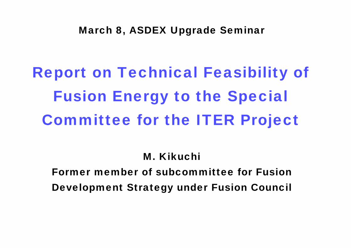
Atomic Energy Commission
Fusion Council
Chair: Prof. N. Inoue
Special committee for the ITER ProjectChair: Prof. H. Yoshikawa
ITER/EDA Technical Subcommittee
Chair: Prof. M. WakataniPlanning and Promotion Subcommittee
Subcommittee for Fusion Development Strategy
Chair: Prof. K. Miya
Chair: Prof. N. Inoue
Structure of Fusion Program Promotion in Japan(before May 17,2000)
2
Two other subcommittes are formed for answering(1) Survey of long term demand and supply of energy sources(2) Feasibility study of alternative energy sources(5) Distribution of resources for research(6) International relations.
For topic (3) above, the Special Committee additionally requested an evaluation of the feasibility of fusion energy as a safe and reliable energy source from the aspects of technical potential, management capability, and characteristics of Japanese industrial structure.
Charge to Subcommittee for Fusion Development Strategy
(3) Technical feasibility of the fusion energy(4) Extension of the program and basic supporting research
3
Members of Subcommittee for Fusion Development Strategy (April 2000)
Nobuyuki Inoue (Chairman) Chairman of Fusion Council Professor, Institute of Advanced Energy, Kyoto University)
Katsunori Abe Professor, Graduate School of Engineering, Tohoku University Kunihiko Okano Research Fellow, Komae Research Laboratory, Nuclear Energy Systems
Department, Central Research Institute of Electric Power Industry,Yuichi Ogawa Professor, High Temperature Plasma Center, University of TokyoMitsuru Kikuchi General Manager, Tokamak Program Division, Department of Fusion Plasma
Research, Japan Atomic Energy Research InstituteShigetada Kobayashi Chairman of the Committee on Nuclear Fusion Research & Development,
Nuclear industry Executive Committee, Japan Electrical Manufacturers' Association(Senior Manager, Advanced Energy Design & Engineering Department, Power Systems & Services Company, Toshiba Corporation)
Satoru Tanaka Professor, Department of Quantum Engineering and Systems Science, Graduate School of Engineering, University of Tokyo
Yoshiaki Hirotani Manager, Department of Project Planning and Promotion, Japan Atomic Industrial Forum, Inc)
Masami Fujiwara Director-General, National Institute of Fusion ScienceShinzaburo Matsuda Director General, Naka Fusion Establishment,
Japan Atomic Energy Research InstituteKenzo Miya Chairman of Planning and Promotion Subcommittee under Fusion Council
(Professor, Graduate School of Engineering, University of Tokyo)
4
Chapter 1 Future Prospects of the Fusion Energy1.1 Situations in the 21st century1.2 Criteria for commercialization1.3 Comparison with other power sources 1.3.1 Resources (fusion, fission, fossil) 1.3.2 CO2 Emissions and Sustainability of Atmosphere 1.3.3 Safety viewed from Biological Hazard Potential 1.3.4 Radioactive Waste and Environmental Adaptability 1.3.5 Plant Characteristics 1.3.6 Economical Efficiency 1.3.7 Use of Fusion other than Electricity1.4 Overall Assessment

Resources required for Fusion Reactor(SSTR is adopted as a reference design)
Bird's-eye view of SSTR
Torus Sport Structure
Vacuum Port
Divertor Maintenance PortDivertor
Negative NBI Port(2Mev,80MW)
Inter-coil Structure
Blankets (Pressurized Water Cooling Breeder)
Upper Maintenance PortTF Coil
Ring PF Coil(5.5T,NbTi)
Vacuum Chamber
Permanent Blanket
Concrete Cryostat
TF Coil Support
(16.5T,(NbTi)3Sn)
5(m)
5(m)
5(m)
0
Plasma Current Ip 12MAToroidal Field Coil Bt 9TMajor Radius R 7m Aspect Ratio A 4.1
Elongation κ95 1.85
Normalized Beta βN 3.5Fusion Output PF 3GW Current Drive Power PCD 60MWNet Electric Output Power PE 1.08GWFusion Gain Q 50Averaged Neutron Wall Load Pneut. 3MW/m2
Design ValueCenter Solenoid Coil
(7T,NbTi)
Resource life : Assuming present-level world electricity is produced by 1500 SSTR Deuterium : almost limitless ; 144ppm in fresh water Lithium : 1.5million years ; 233Gtons in sea-water Beryllium : 70,000 years ; 100Mtons (gross mineral resources)Niobium : 70,000 years ; 700Mtons (gross mineral resources)
5
6
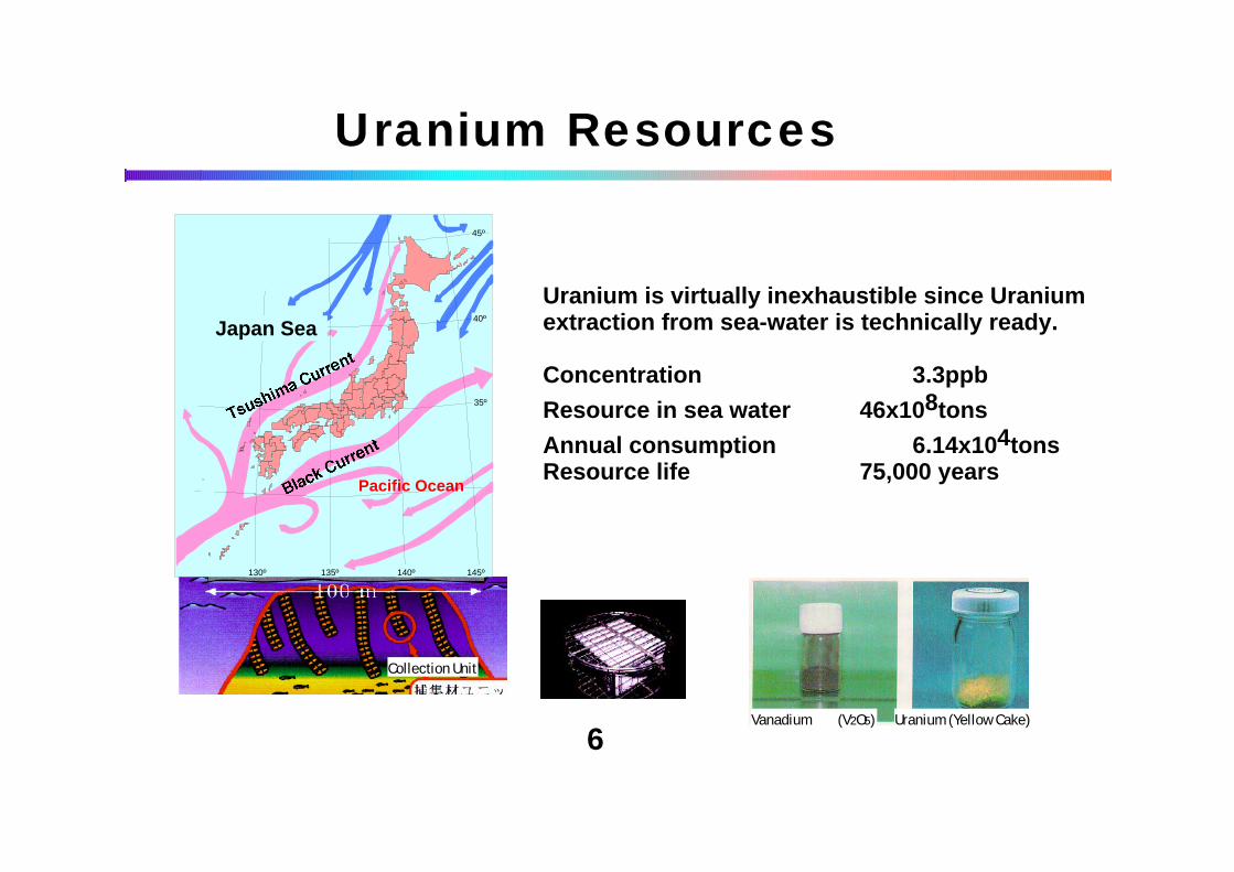
Uranium Resources
Uranium is virtually inexhaustible since Uranium extraction from sea-water is technically ready.
Concentration 3.3ppb
Resource in sea water 46x108tons
Annual consumption 6.14x10⁴tonsResource life 75,000 years
Vanadium (V2O5) Uranium (Yellow Cake)
Collection Unit
Pacific Ocean
Japan Sea
35º
40º
45º
145º140º135º130º
30º
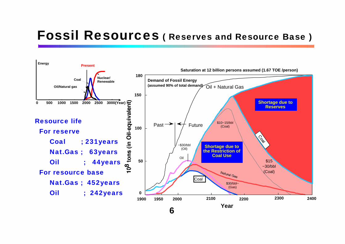
2400
Year
Saturation at 12 billion persons assumed (1.67 TOE /person)180
150
100
50
0
1900 1950 2000 2100 2200 2300
Demand of Fossil Energy(assumed 90% of total demand) Oil + Natural Gas
Past Future
~$30/bbl(Oil)
Oil
$30/bbl~(Gas)
$10~15/bbl(Coal)
$15~30/bbl(Coal)
Coal
Shortage due to the Restriction of
Coal Use
Fossil Resources ( Reserves and Resource Base )
Resource life For reserve
Coal ; 231yearsNat.Gas ; 63yearsOil ; 44years
For resource baseNat.Gas ; 452yearsOil ; 242years
6
0 500 1000 1500 2000 2500 3000(Year)
EnergyPresent
Coal
Oil/Natural gas
Nuclear/Renewable
Shortage due to Reserves
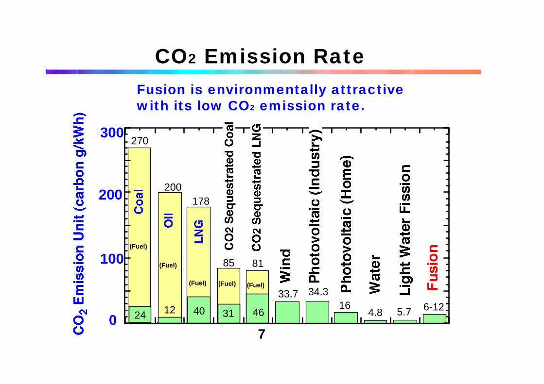
0
100
200
300
34.333.7
178
5.7 6-12
85 81
270
200
1634.333.7
4.831 46
(Fuel) (Fuel)(Fuel)
(Fuel)
(Fuel)
401224
CO2 Emission RateFusion is environmentally attractive with its low CO2 emission rate.
7
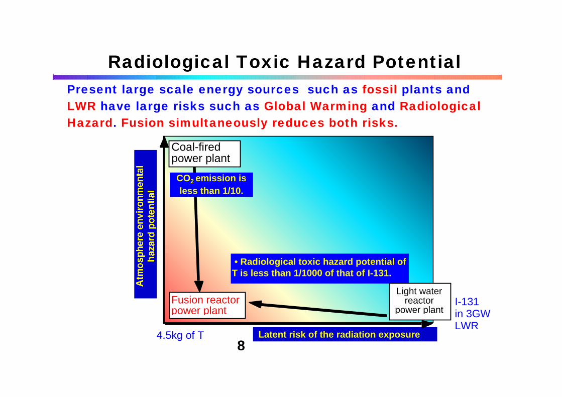
8
Fusion reactor power plant
Coal-fired power plant
Latent risk of the radiation exposure
CO2 emission is less than 1/10.
• Radiological toxic hazard potential of T is less than 1/1000 of that of I-131.
Light water reactor
power plant
Radiological Toxic Hazard PotentialPresent large scale energy sources such as fossil plants and LWR have large risks such as Global Warming and Radiological Hazard. Fusion simultaneously reduces both risks.
I-131 in 3GW LWR
4.5kg of T

Long Term Waste Hazard Potential
Radiological toxic hazard potential of fusion plant is much smaller than fission and even lower than coal ash (Th-232,U-238)
1 07
1 09
1 01 1
1 01 3
1 01 5
1 0- 4 1 0- 2 1 00 1 02 1 04 1 06
Y e a r
1 01 2
1 01 4
1 01 6
1 01 8
1 02 0
1 0- 4 1 0- 2 1 00 1 02 1 04 1 06
Y e a r
Light water reactorFusion reactor (SSTR)
Coal-fired power
Light water reactor
Fusion reactor (SSTR)
Coal-fired power
9

Used disposal unit prices are low-level waste (¥ 1200000/m3), high βγ waste (¥ 2400000/ m3) and high-level radioactive waste (five hundred million yen/ m3)
Waste Management
Disposal cost is smaller than that for LWR spent fuel management.
1000
10 4
10 5
10 6
10 7
10 8
Burn-up ashes from the coal-
fired plant
Fusion reactor Boiling water reactor
High-level radioactive waste High βγ waste Low-level radioactive waste TotalFission reactor 90 billion yen 3.84 billion yen 11.7 billion yen 10.554 billion yenwith 1GW electricity / 180 m3 / 1600 m3 / 9750 m3Fusion reactor(SSTR, - 6 billion yen 30.12 billion yen 36.12 billion yen1.08 GW electricity) / 2500 m3 / 25100 m3
10

Economical Efficiency
11
Geothermal energy
0.1 0.5 1 5 10 50 1001
5
10
50
100
500104 yen/kW
Normalized COE (COEn)
Power plants now in use(Thermal power,Hydropower,Nuclear power)
LNG-fired power plant with CO2 sequestration
Coal-fired power plant with CO2 sequestration
Ocean thermal power
Wind power plant
Future prediction
Future prediction
Target region of fusion power
Photovoltaic power system for utility application
0 1.0 2.0 Upper value
Lower value
Normalized cost of electricity (COEn)
00
2000
4000
6000
8000
10000
20 40 60 80 100Unit cost of construction (x 10 kyen/kW)
Electricity power1 GWe
2 GWe Target ofSSTR[1.3.6.2-3]
[Table1.3.6.2-1]A
C [Table1.3.6.2-1]
Target of CREST[1.3.6.2.-2]
A-BWR(Kashiwazaki Unit 6, Unit 7)
A-BWR(Fukushima Power Plant I Unit 7, Unit 8),future plan
B
A-SSTR[1.3.6.2-4]Target of
1) I f fusion power plants are forced to be competitive only for the COE issue, a COEn of 0 .5~0.7 must be realized in future. 2) I f fusion COEn wil l be much more than 1.5, fusion wil l be noncompetit ive. Even i f f ission plants wil l be unavailable for one reason or other, the fossil power plants with CO2 sequestration systems will need lower cost than the fusion plants. Furthermore, the cost of CO2 sequestration will be reduced in future.
12
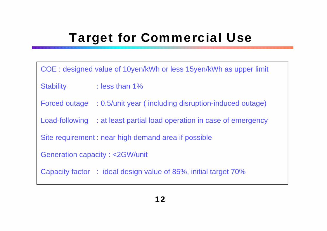
Target for Commercial Use
COE : designed value of 10yen/kWh or less 15yen/kWh as upper limit
Stability : less than 1%
Forced outage : 0.5/unit year ( including disruption-induced outage)
Load-following : at least partial load operation in case of emergency
Site requirement : near high demand area if possible
Generation capacity : <2GW/unit
Capacity factor : ideal design value of 85%, initial target 70%
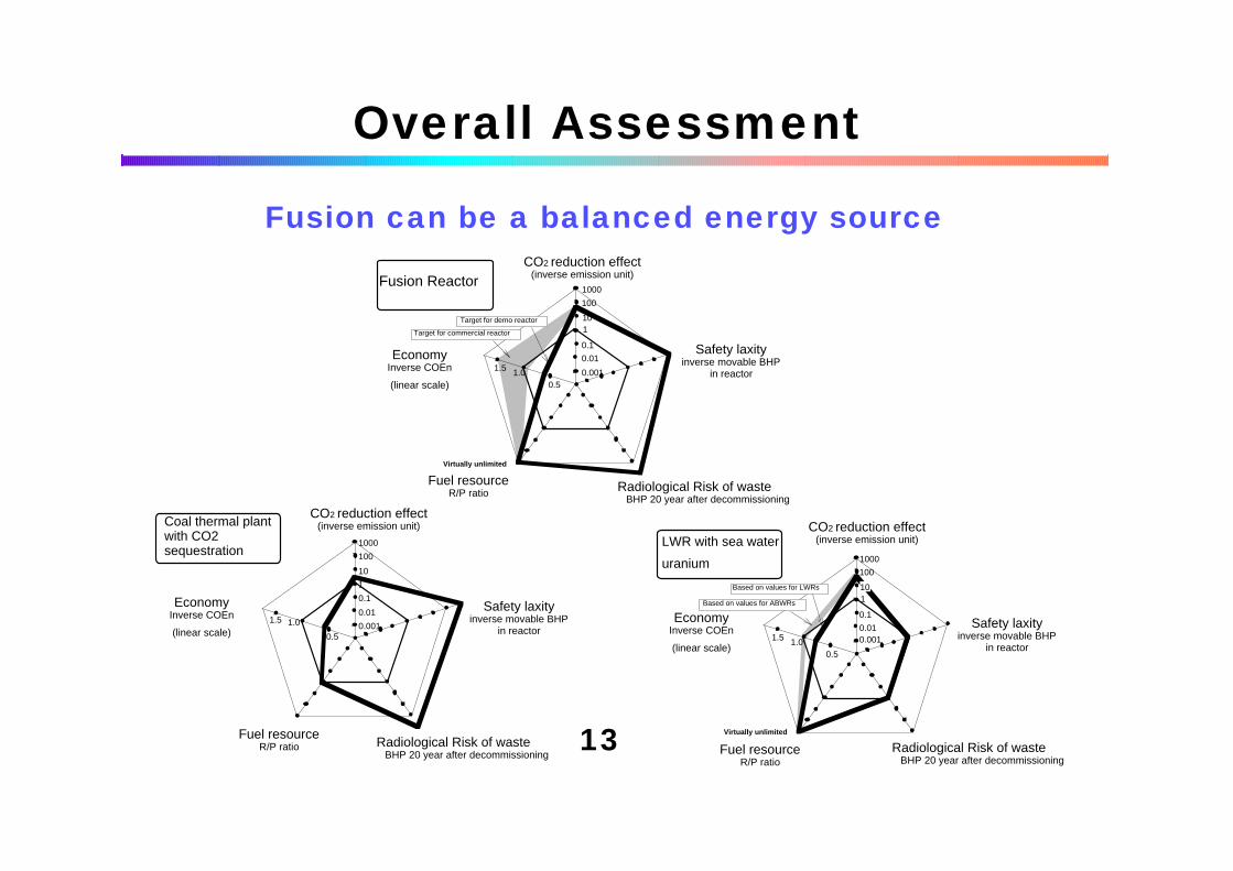
Overall Assessment
Coal thermal plant with CO2 sequestration
EconomyInverse COEn
(linear scale)
Fuel resourceR/P ratio Radiological Risk of waste
BHP 20 year after decommissioning
Safety laxityinverse movable BHP
in reactor
CO2 reduction effect(inverse emission unit)
1.5 1.0
0.50.001
0.01
0.1
1
10
100
1000 LWR with sea water
uranium
1.5 1.00.5
0.0010.01
0.1
110
100
1000
Virtually unlimited
Based on values for ABWRs
Based on values for LWRs
Safety laxityinverse movable BHP
in reactor
CO2 reduction effect(inverse emission unit)
EconomyInverse COEn
(linear scale)
Fuel resourceR/P ratio
Radiological Risk of waste BHP 20 year after decommissioning
Fusion Reactor
1.5 1.00.5
0.001
0.01
0.1
110
100
1000
Target for demo reactor
Target for commercial reactor
CO2 reduction effect(inverse emission unit)
Safety laxityinverse movable BHP
in reactor
EconomyInverse COEn
(linear scale)
Fuel resourceR/P ratio Radiological Risk of waste
BHP 20 year after decommissioning
Virtually unlimited
Fusion can be a balanced energy source
13
Chapter 2 Development Strategy based on ITER Project2.1 Approach - Integration and Phased Development2.2 ITER as an Experimental Reactor 2.2.1 ITER 2.2.2 What will be realized on ITER 2.2.3 Significance and cost sharing phylosophy 2.2.4 Value of hosting ITER to Japan 2.2.5 Tokamak research insupport of ITER2.3 From ITER to DEMO2.4 Summary-Placement of ITER in development strategy
14
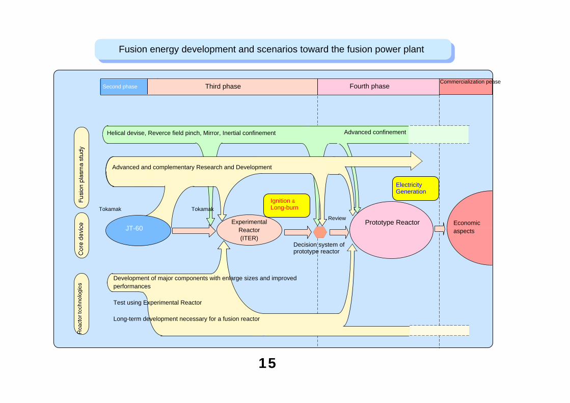
Fusion energy development and scenarios toward the fusion power plant
Prototype Reactor
Ignition &Long-burn
Third phaseSecond phase Fourth phase
Tokamak
Commercialization pease
JT-60
Decision system of prototype reactor
Electricity Generation
Advanced and complementary Research and Development
Helical devise, Reverce field pinch, Mirror, Inertial confinement Advanced confinement
Tokamak
Development of major components with enlarge sizes and improvedperformances
Test using Experimental Reactor
Long-term development necessary for a fusion reactor
Economicaspects
ExperimentalReactor(ITER)
Review
15
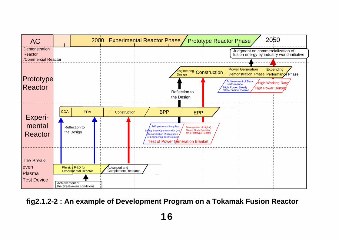
16fig2.1.2-2 : An example of Development Program on a Tokamak Fusion Reactor
Experi-mental Reactor
Prototype Reactor
AC
The Break-even PlasmaTest Device
Reflection to the Design
Demonstration Reactor/Commercial Reactor
Engineering Design
Expending Performance Phase
High Working Rate
CDA EDA Construction BPP EPP
Reflection to the Design
20502000 Experimental Reactor Phase
Self-Igniton and Long Burn
Physics R&D for Experimental Reactor
Advanced and Complement Research
Achievement ofthe Break-even conditions
Development of High Q Steady State Operation for a Prototype Reactor
Judgment on commercialization offusion energy by industry world initiative
Achievement of Basic Performance
High Power Density
Test of Power Generation Blanket
Prototype Reactor Phase
ConstructionPower Generation Demonstration Phase
High Power Steady State Fusion Plasma
Steady State Operation with Q=5
Demonstration of Integration of Engineering Technologies
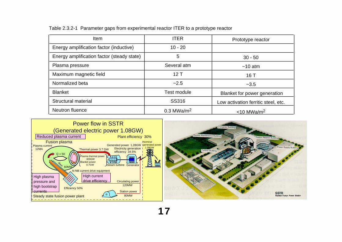
Table 2.3.2-1 Parameter gaps from experimental reactor ITER to a prototype reactor
Item
Energy amplification factor (inductive)
Energy amplification factor (steady state)
Plasma pressure
Maximum magnetic field
Normalized beta
Blanket
Structural material
Neutron fluence
ITER
10 - 20
5
Several atm
12 T
~2.5
Test module
SS316
0.3 MWa/m2
Prototype reactor
30 - 50
~10 atm
16 T
~3.5
Blanket for power generation
Low activation ferritic steel, etc.
<10 MWa/m2
17
Power flow in SSTR(Generated electric power 1.08GW)
Plant efficiency 30%Nominal generated power 1.08GW
Steady state fusion power plant
Thermal power 3.7 GW Electricity generationefficiency 34.5%
Generated power 1.28GW
Q = 50
Fusion plasmaPlasma current 12MA
Efficiency 50%
N-NB current drive equipment
GeneratorSteam turbine
Reduced plasma current
High currentdrive efficiency
High plasma pressure and high bootstrapcurrents
60MW
Circulating power120MW
Station power
80MW
Plasma thermal power 300GWBlanket power 0.7GW
Chapter 3 Technical Issues and Future Prospects
3.1 Fusion plasma technology3.2 Fusion reactor technology3.3 Blanket and material development3.4 Safety related technology3.5 Operation and maintenance3.6 View from Industry3.7 Competitiveness in the Market3.8 Summary-Technological Prospects
18
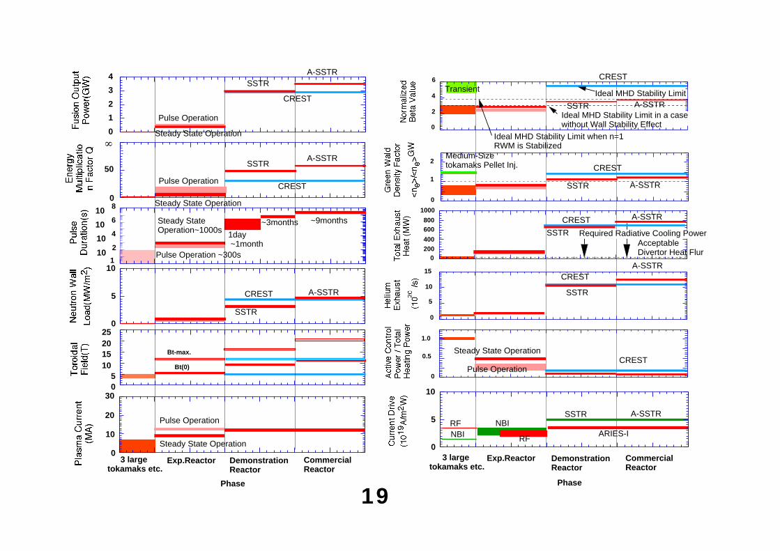
410 610 8
2
Steady State Operation~1000s
Pulse Operation ~300s
1day ~1month
~3months ~9months
10
101
05
10152025
Bt-max.
Bt(0)
0
0
1
2
3
4
Pulse Operation
Steady State Operation
SSTR
CREST
A-SSTR
Pulse Operation
Steady State Operation0
50
CREST
SSTRA-SSTR
0
10
5 CREST
SSTR
A-SSTR
Exp.Reactor
Phase
3 large tokamaks etc.
DemonstrationReactor
CommercialReactor
Pulse Operation
Steady State Operation
30
10
20
0
Transient
Ideal MHD Stability Limit in a case without Wall Stability Effect
6
4
2
0
Ideal MHD Stability Limit when n=1 RWM is Stabilized
CREST
SSTR A-SSTR
Medium-Size tokamaks Pellet Inj.
0
2
1SSTR
CREST
A-SSTR
Acceptable Divertor Heat Flur
0200400
600800
1000
Required Radiative Cooling Power
CREST
SSTR
A-SSTR
15
10
5
CREST
SSTR
A-SSTR
0
0.5
1.0
Pulse Operation
Steady State OperationCREST
Phase
3 large tokamaks etc.
Exp.Reactor DemonstrationReactor
CommercialReactor
0
5
10
SSTR A-SSTR
NBIRF
RF
NBIARIES-I
Ideal MHD Stability Limit
19
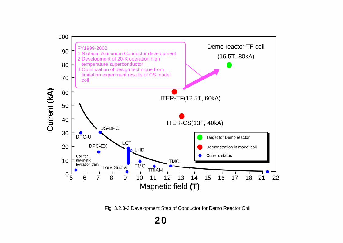
20
10
20
30
40
50
60
70
5 6 7 8 9 10 11 12 13 14
Demonstration in model coil
Current status
Magnetic field (T)
ITER-TF(12.5T, 60kA)
ITER-CS(13T, 40kA)US-DPC
DPC-U
DPC-EXLCT
LHD
TMCTRIAM
TMCTore Supra
80
90
100
15 16 170 18 21 22
Demo reactor TF coil
(16.5T, 80kA)
Target for Demo reactor
FY1999-20021 Niobium Aluminum Conductor development2 Development of 20-K operation high temperature superconductor3 Optimization of design technique from limitation experiment results of CS model coil
Fig. 3.2.3-2 Development Step of Conductor for Demo Reactor Coil
Coil for magnetic levitation train
21
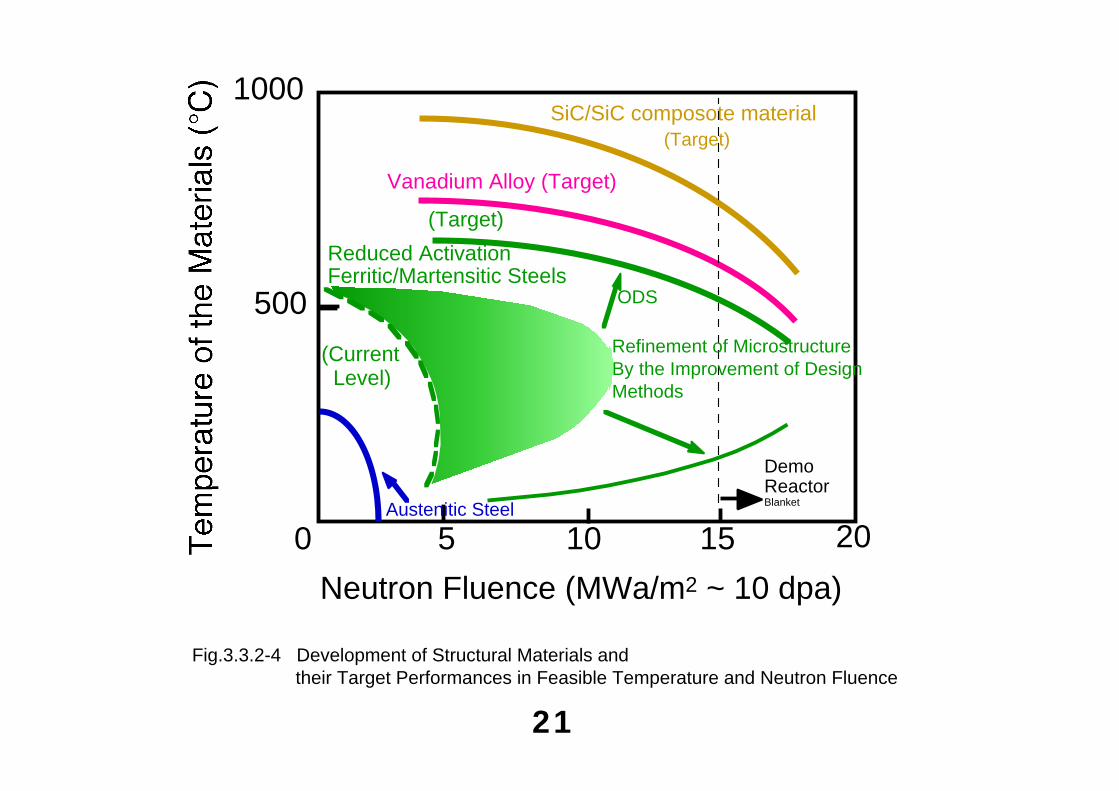
Neutron Fluence (MWa/m2 ~ 10 dpa)
SiC/SiC composote material(Target)
0 5 10 15 20
1000
500
Vanadium Alloy (Target)
Reduced Activation Ferritic/Martensitic Steels
Demo ReactorBlanket
ODS
(Target)
Refinement of MicrostructureBy the Improvement of Design Methods
Austenitic Steel
(Current Level)
Fig.3.3.2-4 Development of Structural Materials and their Target Performances in Feasible Temperature and Neutron Fluence
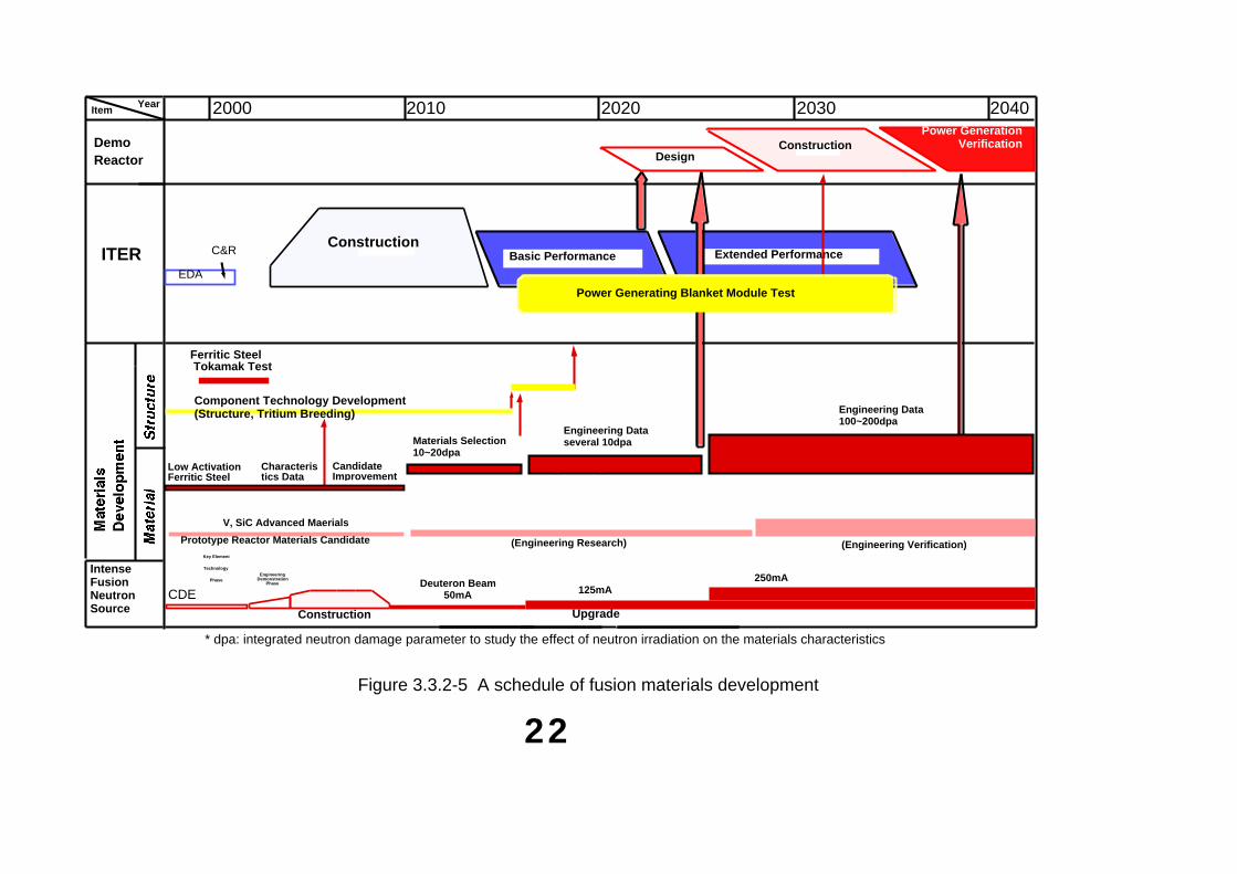
ConstructionBasic Performance Extended Performance
ItemYear
DemoReactor
ITER
IntenseFusionNeutronSource
ConstructionPower Generation
Verification
C&R
EDA
Ferritic Steel Tokamak Test
Component Technology Development(Structure, Tritium Breeding)
Low Activation Ferritic Steel
Characteristics Data
Construction
Candidate Improvement
V, SiC Advanced Maerials
Prototype Reactor Materials Candidate (Engineering Research) (Engineering Verification)
Materials Selection10~20dpa
Engineering Dataseveral 10dpa
Engineering Data100~200dpa
CDE
Key Element
Technology
PhaseEngineering
DemonstrationPhase Deuteron Beam
50mA 125mA250mA
Upgrade
* dpa: integrated neutron damage parameter to study the effect of neutron irradiation on the materials characteristics
2000 2010 2020 2030 2040
Power Generating Blanket Module Test
Design
Figure 3.3.2-5 A schedule of fusion materials development
22
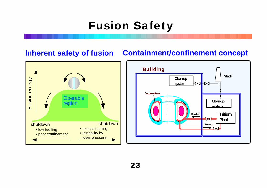
Fuelling
Exsaust
BuildingStack
Vacuum Vessel
Tritium Plant
Clean-up system
Clean-up system
Fusion Safety
Inherent safety of fusion Containment/confinement concept
23
shutdown shutdown• low fuelling• poor confinement
• excess fuelling• instability by over pressure
Operable region
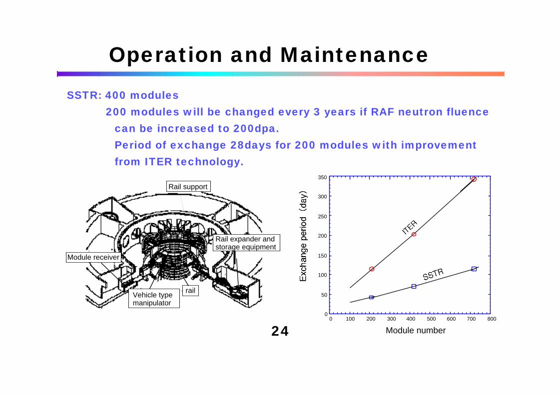
Operation and Maintenance
24
SSTR: 400 modules 200 modules will be changed every 3 years if RAF neutron fluence can be increased to 200dpa.
Period of exchange 28days for 200 modules with improvement from ITER technology.
0
50
100
150
200
250
300
350
0 100 200 300 400 500 600 700 800
Module number
Vehicle type manipulator
Rail expander and storage equipment
rail
Rail support
Module receiver
5.4 Control of burning plasma and technologies addressed in ITER
Control of burning plasmaSelf-heating power produced by the fusion reaction will be applied to the burning
plasma itself, while only plasma heating from the external sources has been examinedin experiments to date.
It is difficult to predict burning plasma behavior with the present knowledge basesince fusion self-heating simulation using external power is difficult. Therefore, withoutunderstanding this burning plasma behavior, it is difficult to clearly predict the technicalfeasibility of fusion energy.
Nonetheless, fusion energy development can be achieved by advancement ofexisting technologies if the control of burning plasma becomes possible. Thus, theunderstanding and control of burning plasma is the last big challenge of fusion energyresearch.
25
New developments for DEMO
Technologies required for DEMO should be developed in parallel with those needed for ITER. By confirming them in ITER, one major ITER design guideline, a "single step to DEMO," can be realized. Major issues of concern are discussed below.
(1) Development of steady-state operation schemeThe basic principle of steady-state operation in tokamaks has been
proven at a number of research institutions in Japan and other countries.
It is important to fully develop steady-state operation methods through the most productive use of existing tokamak devices and to apply their performances to ITER operation, especially to the burning plasma in ITER.
At the same time, it is important to establish operational methods that avoid plasma disruptions, which preclude steady-state operation.
26
(2) Development of high-temperature blanket test modules The blanket plays three important roles, neutron shielding, tritium breeding,
and extraction of high-temperature thermal energy. The latter will produce steam for generation of electricity.
To accomplish the technologies relevant to these roles, a high-temperature blanket is required. Developed in ITER, its design will be available for DEMO.
(3) Neutron irradiation testDevelopment of reduced activation materials that allow intense high-energy
neutron irradiation and high-temperature operation is required to enhance safety and economics of fusion.
Leading candidates for blanket structural materials to be used in DEMO and beyond have been identified. However, performance of these materials should be confirmed by neutron irradiation tests, as the material database has not been satisfactorily completed at present. Neutrons produced in ITER can be used for irradiation tests at low fluence and for component tests.
27
5.9 Conclusion of Part 1The technical feasibility of fusion energy will be confirmed by
demonstrating control of burning fusion plasma, by establishing the technical feasibility of an integrated fusion device, and by accomplishing safety and reliability in ITER.
Furthermore, a high-performance fusion reactor will be realized by establishing steady-state operation. Most major technologies required for the DEMO reactor and beyond can be developed as an extension of ITER.
Therefore, the prospects of fusion development for the DEMO reactor and beyond will become clearer during the ITER program, as compared to the present situation where clarification of physical phenomena receives more emphasis.
In addition, it is possible that the construction cost of the DEMO reactor will be lower than that of ITER due to development of materials, technological innovations, and the progress of plasma physics. A similar possibility could apply to a commercial fusion power station that would follow DEMO.
28