Embed Size (px)
Citation preview

Request For Quotation
Collective No: 9900009061 Orpic Refineries LLC
Vendor Code: 1000
Vendor Name: Orpic
Vendor Name: Orpic
City:
Country:
P.O. Box: PC:
Contact Person:
Email Address:
Tel No:
Information
THIS IS NOT AN ORDERSubmission Date: 05.09.2016
Floating Date: 15.08.2016
P\C Officer: Abdulaziz Al Ghaithi
Telephone:
Fax:
Email: ABDULAZIZ.ABDULLAH.ALGHAITHI@O
Internal Number: 6000022815
Submission Date & Location
Kindly submit your Quotation on or before 05.09.2016 by 23:59:59 hrs.
If supplier copies the procurement officer while submitting his offer, his bids/offer will be rejected.
Submission Details
Quotations and technical submissions (if applicable) shall be submitted by email to [email protected]. The emailsubject line shall include the RFQ Collective Number. For any further clarifications, please contact the respectiveprocurement officer on the Email printed above. Failure to comply with any of the submission instructions shall result indisqualification of the Quotation.
For Payment concerns, please submit original invoice to Email : [email protected]
[Bidder to complete the following declaration in RFQ submission]
Dear Procurement Officer
Having carefully examined the Request For Quotation (RFQ) and its attached Instructions to Bidders and GeneralConditions for Purchases and Minor Services, we offer to supply the Goods and Services for the Prices submitted in thisQuotation.
We confirm that our Quotation is made in full conformity with the RFQ, the Instructions to Bidders, specifications, GeneralConditions for Purchases and Minor Services and all Clarifications and Addenda issued during the RFQ period.
If our Quotation is accepted and a Purchase Order or Service Order issued by Orpic we agree to deliver the Goods andServices in full accordance with the RFQ and our Quotation.
We agree to abide by this Quotation for a period of ninety (90) days from the Submission Date and it shall remain bindingupon us and may be accepted at any time before the expiration of this period.
Dated _ _ _ _ _ _ _ _ _ .
Page 1 of 11

Request For Quotation
Collective No: 9900009061 Orpic Refineries LLC
Signed _ _ _ _ _ _ _ _ _ _ _ _ _.
Name: _ _ _ _ _ _ _ _ _ _ _ _ _ _ _ _ _ _ _ _ .
Title: _ _ _ _ _ _ _ _ _ _ _ _
for and on behalf of_ _ _ _ _ _ _ _ _ _ _ _ _ _ _ _ _
Order Currency:______________
ItemNo.
Material Description Quantity UOM UnitCost
LineCost
10 Junction Box(Data sheet attached) 3 EA
PO Item Text: Junction box as per the attached datasheetJunction Box suitable for terminating incoming cables of 2X4CX240Sq.mm Cu. Cables and outgoing 1X4CX120 Sq.mm Cu. Cables.Incoming cables armored and lead sheathed. Outgoing cables arearmored and not lead sheathed.Minimum 415V rating. Suitable for Zone 2, Group IIC hazardous areawith temperature class T3 (min.) at 42 C, Ex"e", IP65 min.Wall/structure mounted type. Hub position & size: bottom, 3 x M 75(with 1 metallic cover plug for permanent use and 2 plastic cover plugfor temporary use), 2 x M 50 threaded 1.5 mm pitch. (with 1 metalliccover plug for permanent use and 1 plastic cover plug for temporaryuse).Terminals shall be suitable for terminating two lead sheathed,Cu/XLPE/PVC/LC/SWA/PVC, 4C-240 sq. mm. (min.) and one 4CX120 sq. mm. (min.) cables.With metal bottom plate for cable gland earth. Metal part inside JBshall be bonded to the plate. Earth boss (with bolt and washers) andearth tag (with bolt, nut and washer) for 35 sq. mm. earth wire shallbe provided outside the JB. Shorting bar rated 250 Amp (minimum)shall be provided on the terminal.
20 Junction Box-light 26 EA
PO Item Text: Weather proof & Dust proof (IP66), suitable for Zone-2, Junction boxcomplete with terminal connector for looping the lighting cables in andout all terminals strip and cable glands suitable for 2 no. 2C x 2.5sq.mm XLPE/LC/SWA/PVC copper conductor cable & 1 no. 1C x2.5sq. mm PVC insulated, unarmoured, copper conductor earthing cableand one spare cable gland.
30 Cables-0.6/1kV Grade, 2Cx2.5 Sq.mm 200.000 M
PO Item Text: 0.6/1kV Grade, 2Cx2.5 Sq.mm Copper conductor, XLPE insulated,Steel Wire Armoured, Flame Retardant cable as per IEC 60502.Cu/XLPE/PVC/SWA/PVC cable for lighting
Page 2 of 11

Request For Quotation
Collective No: 9900009061 Orpic Refineries LLC
ItemNo.
Material Description Quantity UOM UnitCost
LineCost
40 2Cx6 Sq.mm DC copper cable 116.000 M
PO Item Text: 2Cx6 Sq.mm DC copper cable from battery charger to the newswitchgear panel in SS-12.
50 Cable-0.6/1kV Grade, 4Cx120 Sq.mm 200.000 M
PO Item Text: 0.6/1kV Grade, 4Cx120 Sq.mm Copper conductor, XLPE insulated,Steel Wire Armoured, Flame Retardant cable as per IEC 60502.Cu/XLPE/PVC/SWA/PVC cable from intermediate Junction Boxes inGulftronics skid to the Enclosure
60 0.6/1kV Grade, 2Cx2.5 Sq.mm 170.000 M
PO Item Text: 0.6/1kV Grade, 2Cx2.5 Sq.mm Copper conductor, XLPE insulated,Steel Wire Armoured, Lead outersheathed, Flame Retardant cable asper IEC 60502. Cu/XLPE/LC/SWA/PVC - Cross-linked polyethyleneinsulated (XLPE 90#), polyvinyl chloride inner sheathed (ST2 90#),lead or lead alloy sheath, galvanized steel wired armoured andpolyvinyl chloride outer sheathed (ST1 80#) cable for lighting.
70 1P x 7/0.53 mm (S01P-1.5I-A) Instr Cable 475.000 M
80 1T x 7/0.53 mm (S01T-1.5I-A) Instr Cable 50.000 M
90 Communication Cable (CAT5e) 50.000 M
100 Control Net coaxial cable AB 1786-RG6 700.000 M
(A)Ex-Works Costs
(B)CIF Costs
(C) Custom Duty
(D) COO Charge
(E) Total Cost (B+C)
Total(In words):
Estimated Weight
Page 3 of 11

DOCUMENTS TO BE SUBMITTED: Bidder to Submit and confirm following alongwith the bid:
1. Tenderer Experience 2. Bidder to confirm complete compliance scope of supply. 3. Bidder to submit quality documents alongwith the bid 4. Bidder to comply with delivery period of 8 weeks DDP Orpic Sohar refinery

09004ed5800f07ee_--_A4_--_.doc
JOB No. JGC DOC. No. REV. 0-3100-25 S-000-1378-002 R2
DATE 01 − OCT − 2003 SHEET 1 OF 35 PREP’D T. Nagayasu
CHK’D S. Watanabe
APP’D H. Furuta
SPECIFICATION
FOR
INSTRUMENT CABLES
SOHAR REFINERY COMPANY L. L. C.
SOHAR REFINERY PROJECT
SOHAR, SULTANATE OF OMAN
REV. DATE PAGE DESCRIPTION PREP’D CHK’D APP’D
0 01 Oct 2003 All For Approval T.N S.W H.F
R 01 Nov 2003 ALL For Construction (OY-JY-E-20870) T.N S.W H.F
R1 25 Apr 2004 ALL For Construction, Revised as per Marked-up T.N S.W H.F
R2 13 Oct 2004 9, 27 For Construction, Revised as per Marked-up T.N S.W H.F
PROJECT SPECIFICATION
FOR CONSTRUCTION
Sohar Refinery Company SOHAR Refinery Project
_____
| |
| |
_____INDRA
18-OCT-2004

JOB CODE: 0-3100-25Sohar Refinery Company SOHAR Refinery Project
DOC NO: S-000-1378-002 rev.R2 Specification for Instrument Cables SHEET : 2 of 35
09004ed5800f07ee_--_A4_--_.doc
CONTENTS
1 SCOPE ........................................................................................................................................................... 3
2 GENERAL..................................................................................................................................................... 4 2.1 Sunlight resistance .................................................................................................................................. 4 2.2 Outer sheath............................................................................................................................................ 4 2.3 Flame retardant cable.............................................................................................................................. 4 2.4 Fire resistant cable .................................................................................................................................. 4 2.5 Intrinsically safe systems cable............................................................................................................... 4 2.6 Others...................................................................................................................................................... 4
3 ELECTRONIC SIGNAL CABLE............................................................................................................... 5 3.1 Overall Screened, Armoured Cables....................................................................................................... 5 3.2 Individual screened, Armoured Cables................................................................................................... 6 3.3 Overall Screened, Non-Armoured Cables .............................................................................................. 7 3.4 Individual screened, Non-Armoured Cables........................................................................................... 8
4 SOLENOID (HIGH CONSUMPTION) / DC POWER SUPPLY CABLE / AC POWER SUPPLY CABLE ................................................................................................................................................................... 9
4.1 Armoured Cables .................................................................................................................................... 9 4.2 Non-Armoured Cables.......................................................................................................................... 10
5 THERMOCOUPLE EXTENSION COMPENSATION CABLE........................................................... 11 5.1 Armoured Cables .................................................................................................................................. 11 5.2 Non-Armoured Cables.......................................................................................................................... 13
6 GROUNDING WIRE ................................................................................................................................. 15
7 TEST AND INSPECTION......................................................................................................................... 16
8 CABLE MARKING.................................................................................................................................... 16
9 END SEALING ........................................................................................................................................... 16
10 IDENTIFICATION OF WIRES................................................................................................................ 17 10.1 Multi-Pairs ............................................................................................................................................ 17 10.2 Triads .................................................................................................................................................... 17 10.3 Colour of Insulation for Cores .............................................................................................................. 18
11 CABLE CODE ............................................................................................................................................ 19 11.1 ELECTRONIC SIGNAL CABLE........................................................................................................ 20 11.2 DC Power Supply / Solenoid Valve (High consumption) / AC Power Supply Cable .......................... 27 11.3 THERMOCOUPLE EXTENSION COMPENSATION CABLE......................................................... 31 11.4 GROUNDING WIRE........................................................................................................................... 35
_____
| |
| |
_____INDRA
18-OCT-2004

JOB CODE: 0-3100-25Sohar Refinery Company SOHAR Refinery Project
DOC NO: S-000-1378-002 rev.R2 Specification for Instrument Cables SHEET : 3 of 35
09004ed5800f07ee_--_A4_--_.doc
1 SCOPE This specification covers the technical requirements for the design, manufacturing, inspection and testing of instrument cables for the SOHAR Refinery Project. The applicable standards to this specification are as follows. BS 1442 : Galvanized mild steel wire for armouring cables.
BS 4066 Part 1 : Method of test on a single vertical insulated wire or cable.
BS 5308 Part 1 : Specification for polyethylene insulated cables.
BS 5467 : Specification for 600/1000V and 1900/3300V armoured electric cables having thermosetting insulation
BS 6004 : Electric cables, PVC insulation, non-armoured cables for voltages up to and including 450/750V, for electric power, lighting and internal wiring
BS 6234 : Specification for polyethylene insulation and sheath of electric cables
BS 6360 : Specification for conductors in insulated cables and cords
IEC 60331 : Tests for electric cables under fire conditions –Circuit integrity -
IEC 60332 : Tests on electric cables under fire conditions
IEC 60502 : Power cables with extruded insulation and their accessories for rated voltages from 1kV(Um=1.2kV)up to 30kV(Um=36kV)
ANSI MC96.1
: Temperature measurement thermocouples
Abbreviations for instrument cables. PEI : Polyethylene insulated
XLPEI : Cross-Linked Polyethylene insulation
AMS : Al-mylar screened
PE : Polyethylene bedding
PVC : Polyvinyl chloride bedding
SWA : Steel wire armoured
PVCS : Polyvinyl chloride sheathed
_____
| |
| |
_____INDRA
18-OCT-2004

JOB CODE: 0-3100-25Sohar Refinery Company SOHAR Refinery Project
DOC NO: S-000-1378-002 rev.R2 Specification for Instrument Cables SHEET : 4 of 35
09004ed5800f07ee_--_A4_--_.doc
2 GENERAL
The following requirements shall be considered and incorporated into design of Instrument cables.
2.1 Sunlight resistance
Vendor shall give a guarantee of non-deterioration of cables as a result of expose to direct sunlight.
2.2 Outer sheath
Colour of outer sheath shall be black except for the following cables; Light blue shall be applied for intrinsically safe cables. The outer sheath colour of Thermocouple Extension and Compensation Cable shall be in accordance with ANSI MC96.1.
2.3 Flame retardant cable
Flame retardant cables shall be used for all cables except grounding wires and shall be designed in accordance with IEC60332 Part 3 – Cat.A.
2.4 Fire resistant cable
Fire resistant cables shall be designed in accordance with IEC60331 Part 21, where required. 2.5 Intrinsically safe systems cable
The intrinsically safe cable shall have the following maximum capacitance, resistance and inductance values;
Capacitance ≤ 0.15 µF/km Resistance ≤ 18.4 Ω/km for 1.0mm²
≤ 12.3 Ω/km for 1.5mm² Inductance ≤ 1.25 mH/km
2.6 Others
(1) Vendor shall manufacture all of instrument cables strictly in accordance with Vendor’s documents (Drawing, Spec. Data sheets and etc.) approved by Purchaser, especially, outer/inner diameters including tolerance and circularity in cross section.
(2) Identifications printed on each core shall be permanent and resist removal.
(3) No splices are permitted in any cable conductors. Continuous conductors shall be used.
_____
| |
| |
_____INDRA
18-OCT-2004

JOB CODE: 0-3100-25Sohar Refinery Company SOHAR Refinery Project
DOC NO: S-000-1378-002 rev.R2 Specification for Instrument Cables SHEET : 5 of 35
09004ed5800f07ee_--_A4_--_.doc
3 ELECTRONIC SIGNAL CABLE
The section covers specific requirements for 300V/500V rated cable based on BS5308 Part 1 to be used for 4-20mA/ Low voltage signal/ DC24V Contact/ Fire and Gas Detector System.
3.1 Overall Screened, Armoured Cables Single Twisted Pair/ Triad/ Multi-pair Overall Shielded (To be installed in hollow block cable trench with backfill for process area. Direct buried for offsite areas and utility areas. Cable tray for all areas.) Construction Conductor : The conductor shall be plain annealed copper in accordance with
BS6360 class 1 (circular solid) or class 2 (concentric circular stranded).
Insulation : Polyethylene (PE) Type 03 as specified in BS6234.
Pair / Triad formation : Two/three insulated conductors shall be uniformly twisted together to form a pair/triad. The lengths of lay used shall be such that the two wires forming each pair are not dissociated by normal handling (The length of lay of any pair shall not exceed 100mm).
Pair identification :
The identification of pair/ triad shall be coloured as specified in para. 10.1 & 10.2 of this specification with pair / triad number.
Cabling : Required number of pair/ triad shall be formed into a cable. Non-hygroscopic filler may be applied to from a circular cable. Binder tape shall be applied over the final layer of pairs.
Overall screen : One drain wire and aluminium backed mylar tape. Aluminium backed mylar tape shall be helically wrapped with 25% of overlap. The aluminium shall be on the inside in continuous contact with the tinned stranded copper drain wire.
Bedding : An extruded bedding of black PE compound shall be applied over the overall screen.
Armour : Single layers of galvanized steel wire armour.
Outer sheath :
An extruded outer sheath of polyvinyl chloride (PVC) compound shall be applied over the galvanized steel wire armour.
Cable size and triad / pair No.
: 1.5mm2 1.0mm2 1.5mm2
: : :
Stranded Solid Solid
; ; ;
1P,2P, 1T, 2T, 3P, 3T 5P, 10P, 20P, 30P, 5T, 10T, 20T 10P, 20P, 5T, 10T, 20T
_____
| |
| |
_____INDRA
18-OCT-2004

JOB CODE: 0-3100-25Sohar Refinery Company SOHAR Refinery Project
DOC NO: S-000-1378-002 rev.R2 Specification for Instrument Cables SHEET : 6 of 35
09004ed5800f07ee_--_A4_--_.doc
3.2 Individual screened, Armoured Cables Individual Pair, Triad Screened Cable (To be installed in hollow block cable trench with backfill for process area. Direct buried for offsite areas and utility areas. Cable tray for all areas.) Construction Conductor : The conductor shall be plain annealed copper in accordance with
BS6360 class 1 (circular solid) or class 2 (concentric circular stranded).
Insulation : Polyethylene (PE) Type 03 as specified in BS6234.
Pair / Triad formation : Two/three insulated conductors shall be uniformly twisted together to form a pair/triad. The lengths of lay used shall be such that the two wires forming each pair are not dissociated by normal handling (The length of lay of any pair shall not exceed 100mm).
Individual screen : One drain wire and aluminium backed mylar tape. Aluminium backed mylar tape shall be helically wrapped with 25% of overlap. The aluminium shall be on the inside in continuous contact with the tinned stranded copper drain wire.
Insulation : A polyester tape shall be applied over the individual screen with a suitable overlap.
Pair identification :
The identification of pair/ triad shall be coloured as specified in para. 10.1 & 10.2 of this specification with pair / triad number.
Cabling : Required number of pair/ triad shall be formed into a cable. Non-hygroscopic filler may be applied to from a circular cable. Binder tape shall be applied over the final layer of pairs.
Overall screen : One drain wire and aluminium backed mylar tape. Aluminium backed mylar tape shall be helically wrapped with 25% of overlap. The aluminium shall be on the inside in continuous contact with the tinned stranded copper drain wire.
Bedding : An extruded bedding of black PE compound shall be applied over the overall screen.
Armour : Single layers of galvanized steel wire armour.
Outer sheath : An extruded outer sheath of polyvinyl chloride (PVC) compound shall be applied over the galvanized steel wire armour.
Cable size and triad / pair No.
: 1.5mm2 1.0mm2
: :
Stranded Solid
; ;
2P, 3P, 2T, 3T 5P, 10P, 20P, 30P, 5T, 10T, 20T
_____
| |
| |
_____INDRA
18-OCT-2004

JOB CODE: 0-3100-25Sohar Refinery Company SOHAR Refinery Project
DOC NO: S-000-1378-002 rev.R2 Specification for Instrument Cables SHEET : 7 of 35
09004ed5800f07ee_--_A4_--_.doc
3.3 Overall Screened, Non-Armoured Cables Single Twisted Pair/ Triad/ Multi-pair Overall Shielded (To be installed in inside building) Construction Conductor : The conductor shall be plain annealed copper in accordance with
BS6360 class 1 (circular solid) or class 2 (concentric circular stranded).
Insulation : Polyethylene (PE) Type 03 as specified in BS6234.
Pair / Triad formation : Two/three insulated conductors shall be uniformly twisted together to form a pair/triad. The lengths of lay used shall be such that the two wires forming each pair are not dissociated by normal handling (The length of lay of any pair shall not exceed 100mm).
Pair identification :
The identification of pair/ triad shall be coloured as specified in para. 10.1 & 10.2 of this specification with pair / triad number.
Cabling : Required number of pair/ triad shall be formed into a cable. Non-hygroscopic filler may be applied to from a circular cable. Binder tape shall be applied over the final layer of pairs.
Overall screen : One drain wire and aluminium backed mylar tape. Aluminium backed mylar tape shall be helically wrapped with 25% of overlap. The aluminium shall be on the inside in continuous contact with the tinned stranded copper drain wire.
Outer sheath :
An extruded outer sheath of polyvinyl chloride (PVC) compound shall be applied over the overall screen.
Cable size and triad / pair No.
: 1.5mm2 1.0mm2
: :
Stranded Solid
; ;
1P, 2P, 3P, 1T, 2T, 3T 5P, 10P, 20P, 30P, 5T, 10T, 20T
_____
| |
| |
_____INDRA
18-OCT-2004

JOB CODE: 0-3100-25Sohar Refinery Company SOHAR Refinery Project
DOC NO: S-000-1378-002 rev.R2 Specification for Instrument Cables SHEET : 8 of 35
09004ed5800f07ee_--_A4_--_.doc
3.4 Individual screened, Non-Armoured Cables Individual Pair, Triad Screened Cable (To be installed in inside building) Construction Conductor : The conductor shall be plain annealed copper in accordance with
BS6360 class 1 (circular solid) or class 2 (concentric circular stranded).
Insulation : Polyethylene (PE) Type 03 as specified in BS6234.
Pair / Triad formation : Two/three insulated conductors shall be uniformly twisted together to form a pair/triad. The lengths of lay used shall be such that the two wires forming each pair are not dissociated by normal handling (The length of lay of any pair shall not exceed 100mm).
Individual screen : One drain wire and aluminium backed mylar tape. Aluminium backed mylar tape shall be helically wrapped with 25% of overlap. The aluminium shall be on the inside in continuous contact with the tinned stranded copper drain wire.
Insulation : A polyester tape shall be applied over the individual screen with a suitable overlap.
Pair identification :
The identification of pair/ triad shall be coloured as specified in para. 10.1 & 10.2 of this specification with pair / triad number.
Cabling : Required number of pair/ triad shall be formed into a cable. Non-hygroscopic filler may be applied to from a circular cable. Binder tape shall be applied over the final layer of pairs.
Overall screen : One drain wire and aluminium backed mylar tape. Aluminium backed mylar tape shall be helically wrapped with 25% of overlap. The aluminium shall be on the inside in continuous contact with the tinned stranded copper drain wire.
Outer sheath :
An extruded outer sheath of polyvinyl chloride (PVC) compound shall be applied over the overall screen.
Cable size and triad / pair No.
: 1.5mm2 1.0mm2
: :
Stranded Solid
; ;
1P, 2P, 3P, 1T, 2T, 3T 5P, 10P, 20P, 30P, 5T, 10T, 20T
_____
| |
| |
_____INDRA
18-OCT-2004

JOB CODE: 0-3100-25Sohar Refinery Company SOHAR Refinery Project
DOC NO: S-000-1378-002 rev.R2 Specification for Instrument Cables SHEET : 9 of 35
09004ed5800f07ee_--_A4_--_.doc
4 SOLENOID (HIGH CONSUMPTION) / DC POWER SUPPLY CABLE / AC POWER SUPPLY CABLE The section covers specific requirements for 0.6 / 1 KV rated cable to be used for solenoid valve/ DC power supply cable / AC power supply cable.
4.1 Armoured Cables Single / Multicore/ Non-shielded Cable (To be installed in hollow block cable trench with backfill for process area. Direct buried for offsite areas and utility areas. Cable tray for all areas.) Construction Conductor : The conductor shall be plain annealed copper in accordance with
BS6360 class 1 (circular solid) or class 2 (concentric circular stranded).
Insulation : Polyethylene (PE) Type 03 as specified in BS6234 or XLPE according to IEC502.
Cabling for multi-core cables
: The required number of core shall be cabled with non-hygroscopic fillers in round shape. Binder tape shall be applied over the final layer of cores.
Bedding : An extruded bedding of black PE compound shall be applied over the binder tape for insulated conductors.
Armour : Single layers of galvanized steel wire armour.
Outer sheath :
An extruded outer sheath of polyvinyl chloride (PVC) compound shall be applied over the galvanized steel wire armour.
Identification :
The identification of cores shall be coloured or numbered as specified in para. 10.3 of this specification.
Cable size and core No.
: 2.5mm2 4.0mm2 6.0mm2 10mm2 16mm2 25mm2 35mm2
: : : : : : :
Stranded Stranded Stranded Stranded Stranded Stranded Stranded
; ; ; ; ; ; ;
2C, 10C, 20C, 30C, 40C 2C, 4C, 6C, 10C, 20C, 30C, 40C 2C, 10C, 20C, 30C 2C, 10C, 20C 2C, 3C 2C 2C
_____
| |
| |
_____INDRA
18-OCT-2004

JOB CODE: 0-3100-25Sohar Refinery Company SOHAR Refinery Project
DOC NO: S-000-1378-002 rev.R2 Specification for Instrument Cables SHEET : 10 of 35
09004ed5800f07ee_--_A4_--_.doc
4.2 Non-Armoured Cables Signal/ Multicore/ Non-shielded Cable (To be installed in inside building) Construction Conductor : Concentric circular stranded (7 strands) conductor composed of
annealed bare copper wires in accordance with BS6360 class2.
Insulation : Polyethylene (PE) Type 03 as specified in BS6234 or XLPE according to IEC502.
Cabling for multi-core cables
: The required number of core shall be cabled with non-hygroscopic fillers in round shape. Binder tape shall be applied over the final layer of cores.
Outer sheath :
An extruded outer sheath of polyvinyl chloride (PVC) compound shall be applied over the binder tape for insulated conductors.
Identification :
The identification of cores shall be coloured or numbered as specified in para. 10.3 of this specification.
Cable size and core No.
: 1.5mm2 1.5mm2 2.5mm2 4.0mm2 6.0mm2 10mm2 16mm2
: : : : : : :
Stranded Solid Stranded Stranded Stranded Stranded Stranded
; ; ; ; ; ; ;
2C 20C, 30C, 40C 2C, 20C, 30C, 40C 2C 2C 2C 2C
_____
| |
| |
_____INDRA
18-OCT-2004

JOB CODE: 0-3100-25Sohar Refinery Company SOHAR Refinery Project
DOC NO: S-000-1378-002 rev.R2 Specification for Instrument Cables SHEET : 11 of 35
09004ed5800f07ee_--_A4_--_.doc
5 THERMOCOUPLE EXTENSION COMPENSATION CABLE
The section covers specific requirements for thermocouple extension cable.
5.1 Armoured Cables Single Twisted Pair/ Multi Pair Thermocouple Extension Cable (To be installed in hollow block cable trench with backfill for process area. Direct buried for offsite areas and utility areas. Cable tray for all areas.) Construction Conductor : KX
EX JX RCA
: : : : : : : :
Positive Negative Positive Negative Positive Negative Positive Negative
; ; ; ; ; ; ; ;
Alloy consisting mainly of nickel and chromium, solid. Alloy consisting mainly of nickel, solid. Alloy consisting mainly of nickel and chromium, solid. Alloy consisting mainly of copper and nickel, solid. Iron, solid. Alloy consisting mainly of copper and nickel, solid. Copper, solid. Alloy consisting mainly of copper and nickel, solid.
Insulation : Polyethylene (PE) Type 03 as specified in BS6234.
Pair / Triad formation : Two insulated conductors shall be uniformly twisted together to form a pair. The lengths of lay used shall be such that the two wires forming each pair are not dissociated by normal handling (The length of lay of any pair shall not exceed 100mm).
Individual screen : One drain wire and aluminium backed mylar tape. Aluminium backed mylar tape shall be helically wrapped with 25% of overlap. The aluminium shall be on the inside in continuous contact with the tinned stranded copper drain wire.
Cabling : Required number of pair shall be formed into a cable. Non-hygroscopic filler may be applied to from a circular cable. Binder tape shall be applied over the final layer of pairs.
Overall screen : One drain wire and aluminium backed mylar tape. Aluminium backed mylar tape shall be helically wrapped with 25% of overlap. The aluminium shall be on the inside in continuous contact with the tinned stranded copper drain wire.
Bedding : An extruded bedding of black PE compound shall be applied over the overall screen.
Armour : Single layers of galvanized steel wire armour.
_____
| |
| |
_____INDRA
18-OCT-2004

JOB CODE: 0-3100-25Sohar Refinery Company SOHAR Refinery Project
DOC NO: S-000-1378-002 rev.R2 Specification for Instrument Cables SHEET : 12 of 35
09004ed5800f07ee_--_A4_--_.doc
Outer sheath :
An extruded outer sheath of polyvinyl chloride (PVC) compound shall be applied over the galvanized steel wire armour. The outer sheath shall be coloured as follows;
KX EX JX RCA
Type Type Type Type
: : : :
Yellow Purple Black Green
Pair identification :
Each insulated conductor in each pair shall be coloued in accordance with ANSI MC96.1 with number of pair for identification.
KX EX JX RCA
: : : : : : : :
Positive Negative Positive Negative Positive Negative Positive Negative
; ; ; ; ; ; ; ;
Yellow Red Purple Red White Red Black Red
Cable size and triad / pair No.
: 1.5mm2 1.0mm2
: :
Solid Solid
; ;
1P,2P 3P, 5P, 10P, 20P, 30P
_____
| |
| |
_____INDRA
18-OCT-2004

JOB CODE: 0-3100-25Sohar Refinery Company SOHAR Refinery Project
DOC NO: S-000-1378-002 rev.R2 Specification for Instrument Cables SHEET : 13 of 35
09004ed5800f07ee_--_A4_--_.doc
5.2 Non-Armoured Cables Single Twisted Pair/ Multi Pair Thermocouple Extension Cable (To be installed in inside building) Construction Conductor : KX
EX JX RCA
: : : : : : : :
Positive Negative Positive Negative Positive Negative Positive Negative
; ; ; ; ; ; ; ;
Alloy consisting mainly of nickel and chromium, solid. Alloy consisting mainly of nickel, solid. Alloy consisting mainly of nickel and chromium, solid. Alloy consisting mainly of copper and nickel, solid. Iron, solid. Alloy consisting mainly of copper and nickel, solid. Copper, solid. Alloy consisting mainly of copper and nickel, solid.
Insulation : Polyethylene (PE) Type 03 as specified in BS6234.
Pair / Triad formation : Two insulated conductors shall be uniformly twisted together to form a pair. The lengths of lay used shall be such that the two wires forming each pair are not dissociated by normal handling (The length of lay of any pair shall not exceed 100mm).
Individual screen One drain wire and aluminium backed mylar tape. Aluminium backed mylar tape shall be helically wrapped with 25% of overlap. The aluminium shall be on the inside in continuous contact with the tinned stranded copper drain wire.
Cabling : Required number of pair shall be formed into a cable. Non-hygroscopic filler may be applied to from a circular cable. Binder tape shall be applied over the final layer of pairs.
Overall screen : One drain wire and aluminium backed mylar tape. Aluminium backed mylar tape shall be helically wrapped with 25% of overlap. The aluminium shall be on the inside in continuous contact with the tinned stranded copper drain wire.
Outer sheath :
An extruded outer sheath of polyvinyl chloride (PVC) compound shall be applied over the overall screen. The outer sheath shall be coloured as follows;
KX EX JX RCA
Type Type Type Type
: : : :
Yellow Purple Black Green
_____
| |
| |
_____INDRA
18-OCT-2004

JOB CODE: 0-3100-25Sohar Refinery Company SOHAR Refinery Project
DOC NO: S-000-1378-002 rev.R2 Specification for Instrument Cables SHEET : 14 of 35
09004ed5800f07ee_--_A4_--_.doc
Pair identification :
Each insulated conductor in each pair shall be coloued in accordance with ANSI MC96.1 with number of pair for identification.
KX EX JX RCA
: : : : : : : :
Positive Negative Positive Negative Positive Negative Positive Negative
; ; ; ; ; ; ; ;
Yellow Red Purple Red White Red Black Red
Cable size and triad / pair No.
: 1.5mm2 1.0mm2
: :
Solid Solid
; ;
1P,2P 3P, 5P, 10P, 20P, 30P
_____
| |
| |
_____INDRA
18-OCT-2004

JOB CODE: 0-3100-25Sohar Refinery Company SOHAR Refinery Project
DOC NO: S-000-1378-002 rev.R2 Specification for Instrument Cables SHEET : 15 of 35
09004ed5800f07ee_--_A4_--_.doc
6 GROUNDING WIRE The section covers specific requirements for 450V/ 750V rated insulated wire based on BS6004 to be used for the grounding.
6.1.1 Conductor The conductors shall consist of annealed copper wires.
6.1.2 Insulation The insulation shall be coloured polyvinyl chloride compound of BS 6004, applied around the conductors.
6.1.3 Insulation colour Green - Yellow : Safety Earth
Green : System Earth, I.S. Earth
6.1.4 Wire size
2.5mm2, 4.0mm2, 6.0mm2, 10mm2, 16mm2, 25mm2, 35mm2, 50mm2, 75mm2
_____
| |
| |
_____INDRA
18-OCT-2004

JOB CODE: 0-3100-25Sohar Refinery Company SOHAR Refinery Project
DOC NO: S-000-1378-002 rev.R2 Specification for Instrument Cables SHEET : 16 of 35
09004ed5800f07ee_--_A4_--_.doc
7 TEST AND INSPECTION Test and inspection shall be carried out as specified in Requisition at manufacturer’s factory in accordance with BS1442, BS5308, BS5467, IEC60332 & IEC60331 and the test reports shall be submitted to the purchaser.
8 CABLE MARKING The following information shall be clearly marked with permanent embossed letters on outer sheath for all cables. If impossible, the cables shall be clearly and permanently marked by printing or another alternate method. Each cable length shall be printed with length marking at regular intervals of one meter and with cable embossing (following details) on the outer sheath at intervals of not more 1 meter. (1) Name of manufacture
(2) Year of manufacture
(3) No. of core/pair/ triad and Conductor Size
(4) Rating voltage
(5) Flame protection code (e.g. IEC332-3-21)
9 END SEALING
After testing, the ends of the cable shall be sealed by an approved method to prevent the ingress of moisture.
_____
| |
| |
_____INDRA
18-OCT-2004

JOB CODE: 0-3100-25Sohar Refinery Company SOHAR Refinery Project
DOC NO: S-000-1378-002 rev.R2 Specification for Instrument Cables SHEET : 17 of 35
09004ed5800f07ee_--_A4_--_.doc
10 IDENTIFICATION OF WIRES
The wire color identification of multi-pairs/ triads base on BS 5308 Part 1, Appendix A.
10.1 Multi-Pairs Identification of pairs:
Pair No. a-wire b-wire Pair No. a-wire b-wire 1 Black Blue 16 Black Orange 2 Black Green 17 Blue Orange 3 Blue Green 18 Green Orange 4 Black Brown 19 Brown Orange 5 Blue Brown 20 White Orange
6 Green Brown 21 Red Orange 7 Black White 22 Black Yellow 8 Blue White 23 Blue Yellow 9 Green White 24 Green Yellow
10 Brown White 25 Brown Yellow
11 Black Red 26 White Yellow 12 Blue Red 27 Red Yellow 13 Green Red 28 Orange Yellow 14 Brown Red 29 Blank Grey 15 White Red 30 Blue Grey
10.2 Triads Identification of triads: (1) One Triad (1T)
a-wire : Black b-wire : Blue c-wire : Green
(2) Multi- Triads
Triad No. a-wire b-wire c-wire Triad No. a-wire b-wire c-wire 1 Black Blue Violet 16 Black Orange Violet 2 Black Green Violet 17 Blue Orange Violet 3 Blue Green Violet 18 Green Orange Violet 4 Black Brown Violet 19 Brown Orange Violet 5 Blue Brown Violet 20 White Orange Violet
6 Green Brown Violet 21 Red Orange Violet 7 Black White Violet 22 Black Yellow Violet 8 Blue White Violet 23 Blue Yellow Violet 9 Green White Violet 24 Green Yellow Violet
10 Brown White Violet 25 Brown Yellow Violet
11 Black Red Violet 26 White Yellow Violet 12 Blue Red Violet 27 Red Yellow Violet 13 Green Red Violet 28 Orange Yellow Violet 14 Brown Red Violet 29 Blank Grey Violet 15 White Red Violet 30 Blue Grey Violet
_____
| |
| |
_____INDRA
18-OCT-2004

JOB CODE: 0-3100-25Sohar Refinery Company SOHAR Refinery Project
DOC NO: S-000-1378-002 rev.R2 Specification for Instrument Cables SHEET : 18 of 35
09004ed5800f07ee_--_A4_--_.doc
10.3 Colour of Insulation for Cores (1) Two core (2C) for AC power
Hot : Red Neutral : Black
(2) Two core (2C) for DC power / Solenoid Valve (High consumption)
Positive (+) : Black Negative (-) : Blue
(3) Multi-cores
Multi-cores shall be numbered for identification as follows: All cores black and identification with both printed numbers and written word, in white, (e.g.: Core 10 would be coloured black and identified by number ’10, TEN’ in white.)
_____
| |
| |
_____INDRA
18-OCT-2004

JOB CODE: 0-3100-25Sohar Refinery Company SOHAR Refinery Project
DOC NO: S-000-1378-002 rev.R2 Specification for Instrument Cables SHEET : 19 of 35
09004ed5800f07ee_--_A4_--_.doc
11 CABLE CODE
Sample S 01 P - 1.5 I - A F a) b) c) d) e) f) g)
a) Cable Type
P: Cable for AC Power – 2 Core S: Overall Screened Cable E: Cable for Core Cable, include 2 core DC power M: Individual Screened Cable Tx: Thermocouple Cable G: Grounding Wire
Note: For thermocouple cable, “x” shows the thermocouple type, e.g. Type K is TK. b) Number of Pairs / Triads / Cores c) Conductor Type
P: Pairs T: Triads C: Cores
d) Cross Section of Cable Conductor (Unit: mm2) e) Segregation
I: Intrinsic Safety (IS), Light Blue Jacket Color Blank: Non IS, Black Jacket Color G: Green Colored Jacket for Grounding Wire Y: Green/Yellow Colored Jacket for Grounding Wire
f) Steel Wire Armored
A: Steel Wire Armored Required Blank: Not Required
g) Fire Protection
Blank: Flame Retardant Cable F: Fire Resistance Cable
_____
| |
| |
_____INDRA
18-OCT-2004

JOB CODE: 0-3100-25Sohar Refinery Company SOHAR Refinery Project
DOC NO: S-000-1378-002 rev.R2 Specification for Instrument Cables SHEET : 20 of 35
09004ed5800f07ee_--_A4_--_.doc
11.1 ELECTRONIC SIGNAL CABLE
11.1.1 Cable for 4-20mA/ Low voltage signal/ DC24V contact
Overall Screened, Armoured Cables Single Twisted Pair/ Triad/ Multi-pair Overall Shielded
(1) Non Intrinsically Safe Circuits
Cable code No. Size Colour
S01P-1.5-A 1P x 7/0.53mm Black S02P-1.5-A 2P x 7/0.53mm Black S03P-1.5-A 3P x 7/0.53mm Black S05P-1.0-A 5P x 1/1.13mm Black S10P-1.0-A 10P x 1/1.13mm Black S20P-1.0-A 20P x 1/1.13mm Black S30P-1.0-A 30P x 1/1.13mm Black S10P-1.5-A 10P x 1/1.38mm Black S20P-1.5-A 20P x 1/1.38mm Black
Cable code No. Size Colour S01T-1.5-A 1T x 7/0.53mm Black S02T-1.5-A 2T x 7/0.53mm Black S03T-1.5-A 3T x 7/0.53mm Black S05T-1.0-A 5T x 1/1.13mm Black S10T-1.0-A 10T x 1/1.13mm Black S20T-1.0-A 20T x 1/1.13mm Black S05T-1.5-A 5T x 1/1.38mm Black S10T-1.5-A 10T x 1/1.38mm Black S20T-1.5-A 20T x 1/1.38mm Black
_____
| |
| |
_____INDRA
18-OCT-2004

JOB CODE: 0-3100-25Sohar Refinery Company SOHAR Refinery Project
DOC NO: S-000-1378-002 rev.R2 Specification for Instrument Cables SHEET : 21 of 35
09004ed5800f07ee_--_A4_--_.doc
(2) Intrinsically Safe Circuits
Cable code No. Size Colour
S01P-1.5I-A 1P x 7/0.53mm Light Blue S02P-1.5I-A 2P x 7/0.53mm Light Blue S03P-1.5I-A 3P x 7/0.53mm Light Blue S05P-1.0I-A 5P x 1/1.13mm Light Blue S10P-1.0I-A 10P x 1/1.13mm Light Blue S20P-1.0I-A 20P x 1/1.13mm Light Blue S30P-1.0I-A 30P x 1/1.13mm Light Blue
Cable code No. Size Colour S01T-1.5I-A 1T x 7/0.53mm Light Blue S02T-1.5I-A 2T x 7/0.53mm Light Blue S03T-1.5I-A 3T x 7/0.53mm Light Blue S05T-1.0I-A 5T x 1/1.13mm Light Blue S10T-1.0I-A 10T x 1/1.13mm Light Blue S20T-1.0I-A 20T x 1/1.13mm Light Blue
_____
| |
| |
_____INDRA
18-OCT-2004

JOB CODE: 0-3100-25Sohar Refinery Company SOHAR Refinery Project
DOC NO: S-000-1378-002 rev.R2 Specification for Instrument Cables SHEET : 22 of 35
09004ed5800f07ee_--_A4_--_.doc
11.1.2 Fire Resistant Cable for 4-20mA/ Low voltage signal/ DC24V contact Overall Screened, Armoured Cables Single Twisted Pair/ Triad/ Multi-pair Overall Shielded (1) Non Intrinsically Safe Circuits
Cable code No. Size Colour
S01P-1.5-AF 1P x 7/0.53mm Black S02P-1.5-AF 2P x 7/0.53mm Black S03P-1.5-AF 3P x 7/0.53mm Black S05P-1.0-AF 5P x 1/1.13mm Black
Cable code No. Size Colour S01T-1.5-AF 1T x 7/0.53mm Black S02T-1.5-AF 2T x 7/0.53mm Black S03T-1.5-AF 3T x 7/0.53mm Black
(2) Intrinsically Safe Circuits
Cable code No. Size Colour
S01P-1.5I-AF 1P x 7/0.53mm Light Blue S02P-1.5I-AF 2P x 7/0.53mm Light Blue S03P-1.5I-AF 3P x 7/0.53mm Light Blue S05P-1.0I-AF 5P x 1/1.13mm Light Blue
Cable code No. Size Colour S01T-1.5I-AF 1T x 7/0.53mm Light Blue S02T-1.5I-AF 2T x 7/0.53mm Light Blue S03T-1.5I-AF 3T x 7/0.53mm Light Blue
_____
| |
| |
_____INDRA
18-OCT-2004

JOB CODE: 0-3100-25Sohar Refinery Company SOHAR Refinery Project
DOC NO: S-000-1378-002 rev.R2 Specification for Instrument Cables SHEET : 23 of 35
09004ed5800f07ee_--_A4_--_.doc
11.1.3 Cable for 4-20mA/ Low voltage signal/ DC24V contact Overall Screened, Non-Armoured Cables Single Twisted Pair/ Triad/ Multi-pair Overall Shielded (1) Non Intrinsically Safe Circuits
Cable code No. Size Colour
S01P-1.5 1P x 7/0.53mm Black S02P-1.5 2P x 7/0.53mm Black S03P-1.5 3P x 7/0.53mm Black S05P-1.0 5P x 1/1.13mm Black S10P-1.0 10P x 1/1.13mm Black S20P-1.0 20P x 1/1.13mm Black S30P-1.0 30P x 1/1.13mm Black
Cable code No. Size Colour S01T-1.5 1T x 7/0.53mm Black S02T-1.5 2T x 7/0.53mm Black S05T-1.0 5T x 1/1.13mm Black S10T-1.0 10T x 1/1.13mm Black S20T-1.0 20T x 1/1.13mm Black
(2) Intrinsically Safe Circuits
Cable code No. Size Colour
S01P-1.5I 1P x 7/0.53mm Light Blue S02P-1.5I 2P x 7/0.53mm Light Blue S03P-1.5I 3P x 7/0.53mm Light Blue S05P-1.0I 5P x 1/1.13mm Light Blue S10P-1.0I 10P x 1/1.13mm Light Blue S20P-1.0I 20P x 1/1.13mm Light Blue S30P-1.0I 30P x 1/1.13mm Light Blue
Cable code No. Size Colour S01T-1.5I 1T x 7/0.53mm Light Blue S02T-1.5I 2T x 7/0.53mm Light Blue S05T-1.0I 5T x 1/1.13mm Light Blue S10T-1.0I 10T x 1/1.13mm Light Blue S20T-1.0I 20T x 1/1.13mm Light Blue
_____
| |
| |
_____INDRA
18-OCT-2004

JOB CODE: 0-3100-25Sohar Refinery Company SOHAR Refinery Project
DOC NO: S-000-1378-002 rev.R2 Specification for Instrument Cables SHEET : 24 of 35
09004ed5800f07ee_--_A4_--_.doc
11.1.4 Individual screened, Armoured Cables Individual Pair/ Triad Screened Cable (1) Non Intrinsically Safe Circuits
Cable code No. Size Colour
M02P-1.5-A 2P x 7/0.53mm Black M03P-1.5-A 3P x 7/0.53mm Black M05P-1.0-A 5P x 1/1.13mm Black M10P-1.0-A 10P x 1/1.13mm Black M20P-1.0-A 20P x 1/1.13mm Black M30P-1.0-A 30P x 1/1.13mm Black
Cable code No. Size Colour M02T-1.5-A 2T x 7/0.53mm Black M03T-1.5-A 3T x 7/0.53mm Black M05T-1.0-A 5T x 1/1.13mm Black M10T-1.0-A 10T x 1/1.13mm Black M20T-1.0-A 20T x 1/1.13mm Black
(2) Intrinsically Safe Circuits
Cable code No. Size Colour
M02P-1.5I-A 2P x 7/0.53mm Light Blue M03P-1.5I-A 3P x 7/0.53mm Light Blue M05P-1.0I-A 5P x 1/1.13mm Light Blue M10P-1.0I-A 10P x 1/1.13mm Light Blue M20P-1.0I-A 20P x 1/1.13mm Light Blue M30P-1.0I-A 30P x 1/1.13mm Light Blue
Cable code No. Size Colour M02T-1.5I-A 2T x 7/0.53mm Light Blue M03T-1.5I-A 3T x 7/0.53mm Light Blue M05T-1.0I-A 5T x 1/1.13mm Light Blue M10T-1.0I-A 10T x 1/1.13mm Light Blue M20T-1.0I-A 20T x 1/1.13mm Light Blue
_____
| |
| |
_____INDRA
18-OCT-2004

JOB CODE: 0-3100-25Sohar Refinery Company SOHAR Refinery Project
DOC NO: S-000-1378-002 rev.R2 Specification for Instrument Cables SHEET : 25 of 35
09004ed5800f07ee_--_A4_--_.doc
11.1.5 Fire Resistant , Individual screened, Armoured Cables Individual Pair/ Triad Screened Cable (1) Non Intrinsically Safe Circuits
Cable code No. Size Colour
M02P-1.5-AF 2P x 7/0.53mm Black M03P-1.5-AF 3P x 7/0.53mm Black M05P-1.0-AF 5P x 1/1.13mm Black
Cable code No. Size Colour M02T-1.5-AF 2T x 7/0.53mm Black M05T-1.0-AF 5T x 1/1.13mm Black
(2) Intrinsically Safe Circuits
Cable code No. Size Colour
M02P-1.5I-AF 2P x 7/0.53mm Light Blue M03P-1.5I-AF 3P x 7/0.53mm Light Blue M05P-1.0I-AF 5P x 1/1.13mm Light Blue
Cable code No. Size Colour M02T-1.5I-AF 2T x 7/0.53mm Light Blue M05T-1.0I-AF 5T x 1/1.13mm Light Blue
_____
| |
| |
_____INDRA
18-OCT-2004

JOB CODE: 0-3100-25Sohar Refinery Company SOHAR Refinery Project
DOC NO: S-000-1378-002 rev.R2 Specification for Instrument Cables SHEET : 26 of 35
09004ed5800f07ee_--_A4_--_.doc
11.1.6 Individual screened, Non-Armoured Cables Individual Pair/ Triad Screened Cable (1) Non Intrinsically Safe Circuits
Cable code No. Size Colour
M02P-1.5 2P x 7/0.53mm Black M03P-1.5 3P x 7/0.53mm Black M05P-1.0 5P x 1/1.13mm Black M10P-1.0 10P x 1/1.13mm Black M20P-1.0 20P x 1/1.13mm Black M30P-1.0 30P x 1/1.13mm Black
Cable code No. Size Colour M03T-1.5 3T x 7/0.53mm Black M05T-1.0 5T x 1/1.13mm Black M10T-1.0 10T x 1/1.13mm Black M20T-1.0 20T x 1/1.13mm Black
(2) Intrinsically Safe Circuits
Cable code No. Size Colour
M02P-1.5I 2P x 7/0.53mm Light Blue M03P-1.5I 3P x 7/0.53mm Light Blue M05P-1.0I 5P x 1/1.13mm Light Blue M10P-1.0I 10P x 1/1.13mm Light Blue M20P-1.0I 20P x 1/1.13mm Light Blue M30P-1.0I 30P x 1/1.13mm Light Blue M03T-1.5I 3T x 7/0.53mm Light Blue M05T-1.0I 5T x 1/1.13mm Light Blue M10T-1.0I 10T x 1/1.13mm Light Blue M20T-1.0I 20T x 1/1.13mm Light Blue
_____
| |
| |
_____INDRA
18-OCT-2004

JOB CODE: 0-3100-25Sohar Refinery Company SOHAR Refinery Project
DOC NO: S-000-1378-002 rev.R2 Specification for Instrument Cables SHEET : 27 of 35
09004ed5800f07ee_--_A4_--_.doc
11.2 DC Power Supply / Solenoid Valve (High consumption) / AC Power Supply Cable
11.2.1 DC Power Supply / Solenoid Valve (High consumption), Two cores, Non-screened, Armoured Cables
(1) Non Intrinsically Safe Circuits
Strand
Cable code No. Size Colour E02C-2.5-A 2C x 7/0.67mm Black E02C-4.0-A 2C x 7/0.85mm Black E02C-6.0-A 2C x 7/1.04mm Black E02C-10-A 2C x 7/1.35mm Black E03C-16-A 3C x 7/1.70mm Black
(2) Intrinsically Safe Circuits
Cable code No. Size Colour
E02C-2.5I-A 2C x 7/0.67mm Light Blue E02C-4.0I-A 2C x 7/0.85mm Light Blue
11.2.2 AC Power Supply, Two Cores, Non-screened, Armoured Cables
(1) Non Intrinsically Safe Circuits
Cable code No. Size Colour P02C-2.5-A 2C x 7/0.67mm Black P02C-4.0-A 2C x 7/0.85mm Black P02C-6.0-A 2C x 7/1.04mm Black P02C-10-A 2C x 7/1.35mm Black P02C-16-A 2C x 7/1.70mm Black P02C-25-A 2C x 7/2.14mm Black P02C-35-A 2C x 7/2.52mm Black
_____
| |
| |
_____INDRA
18-OCT-2004

JOB CODE: 0-3100-25Sohar Refinery Company SOHAR Refinery Project
DOC NO: S-000-1378-002 rev.R2 Specification for Instrument Cables SHEET : 28 of 35
09004ed5800f07ee_--_A4_--_.doc
11.2.3 Multi-Cores, Non-screened, Armoured Cables (1) Non Intrinsically Safe Circuits
Cable code No. Size Colour E10C-2.5-A 10C x 7/0.67mm Black E20C-2.5-A 20C x 7/0.67mm Black E30C-2.5-A 30C x 7/0.67mm Black E40C-2.5-A 40C x 7/0.67mm Black E04C-4.0-A 4C x 7/0.85mm Black E06C-4.0-A 6C x 7/0.85mm Black E10C-4.0-A 10C x 7/0.85mm Black E20C-4.0-A 20C x 7/0.85mm Black E30C-4.0-A 30C x 7/0.85mm Black E40C-4.0-A 40C x 7/0.85mm Black E10C-6.0-A 10C x 7/1.04mm Black E20C-6.0-A 20C x 7/1.04mm Black E30C-6.0-A 30C x 7/1.04mm Black E10C-10-A 10C x 7/1.35mm Black E20C-10-A 20C x 7/1.35mm Black
(2) Intrinsically Safe Circuits
Cable code No. Size Colour
E02C-2.5I-A 2C x 7/0.67mm Light Blue E20C-2.5I-A 20C x 7/0.67mm Light Blue E30C-2.5I-A 30C x 7/0.67mm Light Blue E40C-2.5I-A 40C x 7/0.67mm Light Blue E02C-4.0I-A 2C x 7/0.85mm Light Blue E20C-4.0I-A 20C x 7/0.85mm Light Blue E30C-4.0I-A 30C x 7/0.85mm Light Blue E40C-4.0I-A 40C x 7/0.85mm Light Blue
_____
| |
| |
_____INDRA
18-OCT-2004

JOB CODE: 0-3100-25Sohar Refinery Company SOHAR Refinery Project
DOC NO: S-000-1378-002 rev.R2 Specification for Instrument Cables SHEET : 29 of 35
09004ed5800f07ee_--_A4_--_.doc
11.2.4 Fire Resistant, Non-screened, Armoured Cables
(1) Non Intrinsically Safe Circuits
Cable code No. Size Colour
E02C-2.5-AF 2C x 7/0.67mm Black E02C-4.0-AF 2C x 7/0.85mm Black
(2) Intrinsically Safe Circuits
Cable code No. Size Colour
E02C-2.5I-AF 2C x 7/0.67mm Light Blue E02C-4.0I-AF 2C x 7/0.85mm Light Blue
_____
| |
| |
_____INDRA
18-OCT-2004

JOB CODE: 0-3100-25Sohar Refinery Company SOHAR Refinery Project
DOC NO: S-000-1378-002 rev.R2 Specification for Instrument Cables SHEET : 30 of 35
09004ed5800f07ee_--_A4_--_.doc
11.2.5 DC Power, Non-screened, Non-Armoured Cables
(1) Non Intrinsically Safe Circuits
Cable code No. Size Colour
E02C-2.5 2C x 7/0.67mm Black E20C-2.5 20C x 7/0.67mm Black E30C-2.5 30C x 7/0.67mm Black E40C-2.5 40C x 7/0.67mm Black E02C-4.0 2C x 7/0.85mm Black
(2) Intrinsically Safe Circuits
Cable code No. Size Colour
E02C-2.5I 2C x 7/0.67mm Light Blue E20C-2.5I 20C x 7/0.67mm Light Blue E30C-2.5I 30C x 7/0.67mm Light Blue E40C-2.5I 40C x 7/0.67mm Light Blue E02C-4.0I 2C x 7/0.85mm Light Blue
11.2.6 AC Power, Non-Armoured Cables
(1) Non Intrinsically Safe Circuits
Cable code No. Size Colour
P02C-2.5 2C x 7/0.67mm Black P02C-4.0 2C x 7/0.85mm Black P02C-6.0 2C x 7/1.04mm Black P02C-10 2C x 7/1.35mm Black P02C-16 2C x 7/1.71mm Black
_____
| |
| |
_____INDRA
18-OCT-2004

JOB CODE: 0-3100-25Sohar Refinery Company SOHAR Refinery Project
DOC NO: S-000-1378-002 rev.R2 Specification for Instrument Cables SHEET : 31 of 35
09004ed5800f07ee_--_A4_--_.doc
11.3 THERMOCOUPLE EXTENSION COMPENSATION CABLE
11.3.1 Type K Extension Cable (KX), Armoured Cables
Cable code No. Size Colour TK01P-1.5-A 1P x 1/1.38mm Yellow TK02P-1.5-A 2P x 1/1.38mm Yellow TK03P-1.0-A 3P x 1/1.13mm Yellow TK05P-1.0-A 5P x 1/1.13mm Yellow TK10P-1.0-A 10P x 1/1.13mm Yellow TK20P-1.0-A 20P x 1/1.13mm Yellow TK30P-1.0-A 30P x 1/1.13mm Yellow
Note: For intrinsically safe circuit, light blue coloured heat shrink tube shall be installed at
both ends.
11.3.2 Type E Extension Cable (EX), Armoured Cables
Cable code No. Size Colour TE01P-1.5-A 1P x 1/1.38mm Purple TE02P-1.5-A 2P x 1/1.38mm Purple TE03P-1.0-A 3P x 1/1.13mm Purple TE05P-1.0-A 5P x 1/1.13mm Purple TE10P-1.0-A 10P x 1/1.13mm Purple TE20P-1.0-A 20P x 1/1.13mm Purple TE30P-1.0-A 30P x 1/1.13mm Purple
Note: For intrinsically safe circuit, light blue coloured heat shrink tube shall be installed at
both ends.
_____
| |
| |
_____INDRA
18-OCT-2004

JOB CODE: 0-3100-25Sohar Refinery Company SOHAR Refinery Project
DOC NO: S-000-1378-002 rev.R2 Specification for Instrument Cables SHEET : 32 of 35
09004ed5800f07ee_--_A4_--_.doc
11.3.3 Type J Extension Cable (JX), Armoured Cables
Cable code No. Size Colour TJ01P-1.5-A 1P x 1/1.38mm Black TJ02P-1.5-A 2P x 1/1.38mm Black TJ03P-1.0-A 3P x 1/1.13mm Black TJ05P-1.0-A 5P x 1/1.13mm Black TJ10P-1.0-A 10P x 1/1.13mm Black TJ20P-1.0-A 20P x 1/1.13mm Black TJ30P-1.0-A 30P x 1/1.13mm Black
Note: For intrinsically safe circuit, light blue coloured heat shrink tube shall be installed at
both ends.
11.3.4 Type R Compensation Cable (RCA), Armoured Cables
Cable code No. Size Colour TR01P-1.5-A 1P x 1/1.38mm Green TR02P-1.5-A 2P x 1/1.38mm Green TR03P-1.0-A 3P x 1/1.13mm Green TR05P-1.0-A 5P x 1/1.13mm Green TR10P-1.0-A 10P x 1/1.13mm Green TR20P-1.0-A 20P x 1/1.13mm Green TR30P-1.0-A 30P x 1/1.13mm Green
Note: For intrinsically safe circuit, light blue coloured heat shrink tube shall be installed at
both ends.
_____
| |
| |
_____INDRA
18-OCT-2004

JOB CODE: 0-3100-25Sohar Refinery Company SOHAR Refinery Project
DOC NO: S-000-1378-002 rev.R2 Specification for Instrument Cables SHEET : 33 of 35
09004ed5800f07ee_--_A4_--_.doc
11.3.5 Type K Extension Cable (KX), Non-Armoured Cables
Cable code No. Size Colour TK01P-1.5 1P x 1/1.38mm Yellow TK02P-1.5 2P x 1/1.38mm Yellow TK03P-1.0 3P x 1/1.13mm Yellow TK05P-1.0 5P x 1/1.13mm Yellow TK10P-1.0 10P x 1/1.13mm Yellow TK20P-1.0 20P x 1/1.13mm Yellow TK30P-1.0 30P x 1/1.13mm Yellow
Note: For intrinsically safe circuit, light blue coloured heat shrink tube shall be installed at
both ends.
11.3.6 Type E Extension Cable (EX), Non-Armoured Cables
Cable code No. Size Colour TE01P-1.5 1P x 1/1.38mm Purple TE02P-1.5 2P x 1/1.38mm Purple TE03P-1.0 3P x 1/1.13mm Purple TE05P-1.0 5P x 1/1.13mm Purple TE10P-1.0 10P x 1/1.13mm Purple TE20P-1.0 20P x 1/1.13mm Purple TE30P-1.0 30P x 1/1.13mm Purple
Note: For intrinsically safe circuit, light blue coloured heat shrink tube shall be installed at
both ends.
_____
| |
| |
_____INDRA
18-OCT-2004

JOB CODE: 0-3100-25Sohar Refinery Company SOHAR Refinery Project
DOC NO: S-000-1378-002 rev.R2 Specification for Instrument Cables SHEET : 34 of 35
09004ed5800f07ee_--_A4_--_.doc
11.3.7 Type J Extension Cable (JX), Non-Armoured Cables
Cable code No. Size Colour TJ01P-1.5 1P x 1/1.38mm Black TJ02P-1.5 2P x 1/1.38mm Black TJ03P-1.0 3P x 1/1.13mm Black TJ05P-1.0 5P x 1/1.13mm Black TJ10P-1.0 10P x 1/1.13mm Black TJ20P-1.0 20P x 1/1.13mm Black TJ30P-1.0 30P x 1/1.13mm Black
Note: For intrinsically safe circuit, light blue coloured heat shrink tube shall be installed at
both ends.
11.3.8 Type R Compensation Cable (RCA), Non-Armoured Cables
Cable code No. Size Colour TR01P-1.5 1P x 1/1.38mm Green TR02P-1.5 2P x 1/1.38mm Green TR03P-1.0 3P x 1/1.13mm Green TR05P-1.0 5P x 1/1.13mm Green TR10P-1.0 10P x 1/1.13mm Green TR20P-1.0 20P x 1/1.13mm Green TR30P-1.0 30P x 1/1.13mm Green
Note: For intrinsically safe circuit, light blue coloured heat shrink tube shall be installed at
both ends.
_____
| |
| |
_____INDRA
18-OCT-2004

JOB CODE: 0-3100-25Sohar Refinery Company SOHAR Refinery Project
DOC NO: S-000-1378-002 rev.R2 Specification for Instrument Cables SHEET : 35 of 35
09004ed5800f07ee_--_A4_--_.doc
11.4 GROUNDING WIRE
Cable code No. Size Colour G01C-2.5G 1C x 2.5mm2 Green G01C-4.0G 1C x 4.0mm2 Green G01C-6.0G 1C x 6.0mm2 Green G01C-10G 1C x 10mm2 Green G01C-16G 1C x 16mm2 Green G01C-25G 1C x 25mm2 Green G01C-35G 1C x 35mm2 Green G01C-50G 1C x 50mm2 Green G01C-70G 1C x 70mm2 Green
Cable code No. Size Colour G01C-2.5Y 1C x 2.5mm2 Green/Yellow G01C-4.0Y 1C x 4.0mm2 Green/Yellow G01C-6.0Y 1C x 6.0mm2 Green/Yellow G01C-10Y 1C x 10mm2 Green/Yellow G01C-16Y 1C x 16mm2 Green/Yellow G01C-25Y 1C x 25mm2 Green/Yellow G01C-35Y 1C x 35mm2 Green/Yellow G01C-50Y 1C x 50mm2 Green/Yellow G01C-70Y 1C x 70mm2 Green/Yellow
_____
| |
| |
_____INDRA
18-OCT-2004

09004ed5801684d4_--_A4_--_.doc
JOB No. JGC DOC. No. REV.
0-3100-25 S-000-1380-203 R2
DATE 31 − AUG − 2004 SHEET 1 OF 46 PREP’D J. Austria
CHK’D A. Cruz
APP’D S. Shimoi
BULK MATERIAL LIST
SOHAR REFINERY COMPANY L. L. C.
SOHAR REFINERY PROJECT
SOHAR, SULTANATE OF OMAN
REV. DATE PAGE DESCRIPTION PREP’D CHK’D APP’D
0 31 AUG. 2004 All For Review JA AC SS R 21 FEB. 2005 All For Construction JA AC SS
R1 09 MAR. 2005 All Updated for 3rd P.O. JA AC SS R2 28 MAR. 2005 7 Updated Quantity of Receptacle for 3rd P.O. JA AC SS
Sohar Refinery Company SOHAR Refinery Project
FOR CONSTRUCTION
SPECIFICATION
_____
| |
| |
_____INDRA
28-MAR-2005

JOB CODE: 0-3100Sohar Refinery Company SOHAR Refinery Project
DOC NO: S-000-1380-203 Rev.R2 Bulk Material List Sheet 2 of 46
09004ed5801684d4_--_A4_--_.doc
PART CODE TABLE
CODE MATERIAL DESCRIPTION
80-2000 Name Tag
82-5000 Local Control Station
82-6000 Junction Box
82-7000 Power Receptacle
82-8000 Local Isolator
82-9000 Miscellaneous Panel and Transformer
83-2000 Convenience Receptacle
83-4000 Lighting / Receptacle Panel Board
84-1000 Earth Reel
_____
| |
| |
_____INDRA
28-MAR-2005

JOB CODE: 0-3100Sohar Refinery Company SOHAR Refinery Project
DOC NO: S-000-1380-203 Rev.R2 Bulk Material List Sheet 3 of 46
09004ed5801684d4_--_A4_--_.doc
ELECTRICAL BULK MATERIAL LIST
MATERIAL DESCRIPTION 1st P.O. 2nd P.O. 3rd P.O. 4th P.O. TOTALCODE
UNIT
CCC DodsalSpare CCC Dodsal Spare CCC Dodsal Spare CCC Dodsal
80-2000
NAME TAG Traffolyte nameplate with 10mm height letters. Size: 30mm x 100mm. Black letters on white background. See attachment 14.
80-2100
Name Tag for Local Control Station. Refer to Attachment 1 for the list of local control station. (HOLD!)
pcs 783 216 999
80-2200
Name Tag for Tumbler Switch. Refer to Attachment 2 for the list of tumbler switch. (HOLD!)
pcs 151 32 183
82-5000 LOCAL CONTROL STATION
82-5100
LOCAL CONTROL STATION FOR AC CIRCUIT Fully assembled control station suitable for Zone 2, Group IIC hazardous area with temperature class T3 (min.) at 42 °C, Ex"e", IP65 min. Design temperature = 5 °C ~ 42 °C. Wall mounted type. Enclosure shall have earth boss with bonding to the internal earth terminal and bottom metal plate. Hub position & sizes: bottom, 1 x M20 and 1 x M25 threaded (Metric) 1.5 mm pitch, complete with 2 rated permanent cover plugs for above hub sizes. With pod lock facility for OFF position. Made of fiber glass, reinforced polyamide material or metal.
82-5110
(TYPE A) Label = OFF – 0 – ON SHELL type, 3 positions with the following schemes: Switch Mechanism = spring-engaging- engaging Connection = (See Attachment 3) See attachment-1 for LCS list. Type CEAG GHG 43-2, SCT
Set 336 98 5 5 444
82-5120
(TYPE B) Label = OFF – 0 – ON with Ammeter SHELL type, 3 positions with the following schemes: Switch Mechanism = spring-engaging- engaging Connection = (See Attachment 4) Ammeter: Min. Class 3 CT connection : 1/n See attachment-1 for LCS list. Type CEAG GHG 43-2, AM45 & SCT Note: Scale of ammeter of spare LCS can be ordered later.
Set 346 118 10 474
_____
| |
| |
_____INDRA
28-MAR-2005

JOB CODE: 0-3100Sohar Refinery Company SOHAR Refinery Project
DOC NO: S-000-1380-203 Rev.R2 Bulk Material List Sheet 4 of 46
09004ed5801684d4_--_A4_--_.doc
MATERIAL DESCRIPTION 1st P.O. 2nd P.O. 3rd P.O. 4th P.O. TOTALCODE
UNIT
CCC DodsalSpare CCC Dodsal Spare CCC Dodsal Spare CCC Dodsal
82-5130
(TYPE C) Label = OFF – 0 – ON SHELL type, 3 positions with the following schemes: Switch Mechanism = spring-engaging- engaging Connection = (See Attachment 5) See attachment-1 for LCS list.
Set 49 49
82-5140
(TYPE D) Label = OFF – 0 – ON SHELL type, 3 positions with the following schemes: Switch Mechanism = spring-engaging- engaging Connection = (See Attachment 6) See attachment-1 for LCS list.
Set 20 20
82-5150
(TYPE E) Label = OFF – 0 – ON with Ammeter SHELL type, 3 positions with the following schemes: Switch Mechanism = spring-engaging- engaging Connection = (See Attachment 7) Ammeter: Min. Class 3 CT connection: 1/n See attachment-1 for LCS list.
Set 4 4
82-5160
(TYPE F) Label = OFF – 0 – ON, OPEN-CLOSE SHELL type, 3 positions with the following schemes: Switch Mechanism = spring-engaging- engaging 2 Positions with the following schemes: Switch Mechanism = engaging- engaging Connection = (See Attachment 8) See attachment-1 for LCS list.
Set 5 5
82-5170
(TYPE G) Label = OFF – 0 – ON SHELL type, 3 positions with the following schemes: Switch Mechanism = spring-engaging- engaging Connection = (See Attachment 9) See attachment-1 for LCS list.
Set 5 5
_____
| |
| |
_____INDRA
28-MAR-2005

JOB CODE: 0-3100Sohar Refinery Company SOHAR Refinery Project
DOC NO: S-000-1380-203 Rev.R2 Bulk Material List Sheet 5 of 46
09004ed5801684d4_--_A4_--_.doc
MATERIAL DESCRIPTION 1st P.O. 2nd P.O. 3rd P.O. 4th P.O. TOTALCODE
UNIT
CCC DodsalSpare CCC Dodsal Spare CCC Dodsal Spare CCC Dodsal
82-5180
(TYPE H) Label = OFF – 0 – ON SHELL type, 3 positions with the following schemes: Switch Mechanism = spring-engaging- engaging Connection = (See Attachment 10) See attachment-1 for LCS list.
Set 4 4
82-5190
(TYPE I) Label = OFF – 0 – ON SHELL type, 3 positions with the following schemes: Switch Mechanism = spring-engaging- engaging Connection = (See Attachment 11) See attachment-1 for LCS list.
Set 14 14
82-6000 JUNCTION BOX
82-6100
6.6 kV Junction Box for Desalter V-1101 Suitable for Zone 2, Group IIC hazardous area with temperature class T3 (min.) at 42 °C, Ex"e", IP65 min. Wall mounted type. Hub position & size: bottom, 4 x M50 threaded (Metric) 1.5 mm pitch (with plastic cover plug for temporary use). Suitable for 6.6 kV approximate size of 600 x 400 x 800mm. With terminal suitable for terminating three 25 sq. mm cable/phase. With earth boss and tag for 70 sq. mm. earth wire. Refer to Attachment-15.
Set 2 2
82-6200
Junction Box for Power Receptacle Minimum 415V rating. Suitable for Zone 2, Group IIC hazardous area with temperature class T3 (min.) at 42 °C, Ex"e", IP65 min. Wall mounted type. Approximate size of 300 x 300 x 250mm. Hub position & size: bottom, 2 x M40 (with 1 metallic cover plug for permanent use and 1 plastic cover plug for temporary use) plus side, 2 x M25 threaded 1.5 mm pitch. (with 1 metallic cover plug for permanent use and 1 plastic cover plug for temporary use). Terminal shall be suitable for terminating two 4C-25 sq. mm. (min.) to 4C-35 sq. mm. (max.) cable and two 4C-50 sq. mm.(min.) to 4C-95 sq. mm. (max.) cables. With metal bottom plate for cable gland earth. Metal part inside JB shall be bonded to the plate. Earth boss (with bolt and washers) and earth tag (with bolt, nut and washer) for 35 sq. mm. earth wire shall be provided outside the JB. Shorting bar rated 60Amp (minimun) shall be provided on the terminal. Refer to Attachment-15.
Set 24 16 40
_____
| |
| |
_____INDRA
28-MAR-2005

JOB CODE: 0-3100Sohar Refinery Company SOHAR Refinery Project
DOC NO: S-000-1380-203 Rev.R2 Bulk Material List Sheet 6 of 46
09004ed5801684d4_--_A4_--_.doc
MATERIAL DESCRIPTION 1st P.O. 2nd P.O. 3rd P.O. 4th P.O. TOTALCODE
UNIT
CCC DodsalSpare CCC Dodsal Spare CCC Dodsal Spare CCC Dodsal
82-7000 POWER RECEPTACLE
82-7100
Power Receptacle 415/240V, 3 Phase, 50 Hz, 60A, 5-Pin, 3 Phase, 4-Wire + Earth, Wall mount type suitable for Zone 2, Group IIC hazardous area with temperature class T3 (min.) at 42 °C. Rating min., Ex"de", IP66. Design temperature = 5 °C ~ 42 °C. Enclosure shall have earth boss with bonding to the internal earth terminal and bottom metal plate. Hub position & size: bottom, M25 metric threaded, 1.5mm pitch (with 1 plastic cover plug for temporary use), switchable only after inserting plug. Type CEAG GHG514 4506 R3001
Set 24 16 40
82-7200
Plug for Power Receptacle Rating: 415/240V, 3 Phase, 50 Hz, 60A, 5-Pin, 3 Phase, 4-Wire + Earth , suitable for Zone 2, Group IIC hazardous area with temperature class T3 (min.) at 42 °C. Rating min., Ex"n" or Ex"e ", Cable grid and neoprene bushing. With Protective cap for cable entry for temporary use. This item shall not be interchangeable with plug for different voltage. Type CEAG GHG514 7506 R0001. Note: One plug for Movable Air Compressor. One plug for Bundle Extractor.
Set 9 5 14
82-8000 LOCAL ISOLATOR
82-8100
Tumbler Switch for Level Gauge and Motor Space Heater Wall mounting type, suitable for Zone 2, Group IIC hazardous area with temperature class T3 (min.) at 42 °C. Rating min., Ex"d" or Ex"e", IP65 min., 240V, single phase, 50Hz, 10 Amp. Design temperature = 5 °C ~ 42 °C. Enclosure shall have earth boss with bonding to the internal earth terminal and bottom metal plate. Suitable for cable gland BOTTOM connection. Padlockable in off position, 2 pole single throw switch, 2-way hub, M25 (Metric) 1.5mm pitch with 1 metallic cover plug for permanent use and 1 plastic plug for temporary use. Refer to attachment 12. Type GHG 43-2
Set 141 29 10 4 184
_____
| |
| |
_____INDRA
28-MAR-2005

JOB CODE: 0-3100Sohar Refinery Company SOHAR Refinery Project
DOC NO: S-000-1380-203 Rev.R2 Bulk Material List Sheet 7 of 46
09004ed5801684d4_--_A4_--_.doc
MATERIAL DESCRIPTION 1st P.O. 2nd P.O. 3rd P.O. 4th P.O. TOTALCODE
UNIT
CCC DodsalSpare CCC Dodsal Spare CCC Dodsal Spare CCC Dodsal
82-8200
Tumbler Switch for 3 Phase Lighting (For Sulfur Storage) Wall mounting type, suitable for Zone 2, Group IIC hazardous area with temperature class T3 (min.) at 42 °C. Rating min., Ex"e", IP65 min., 415V, 3 phase, 4-wire, 50Hz, 10 Amp. Design temperature = 5 °C ~ 42 °C. Enclosure shall have earth boss with bonding to the internal earth terminal and bottom metal plate. Suitable for cable gland BOTTOM connection. 4 pole single throw switch, 2-way hub, M20 (Metric) 1.5mm pitch with 2 plastic plugs for temporary use. Suitable for 2 x 4C-4 sq. mm. XLPE/SWA/PVC cables. Refer to attachment 13.
Set 3 3
82-9000 MISCELLANEOUS PANEL AND TRANSFORMER
82-9100
Distribution Panel (MOV Panel) Refer to S-000-1381-112 - Data Sheet for Lighting / Power Distribution Panel Boards (Outdoor).
Set 9 21 30
82-9200
Electrical Heat Trace Panel Refer to S-000-1381-112 - Data Sheet for Lighting / Power Distribution Panel Boards (Outdoor).
Set 1 1
82-9300
Transformer (690TR401) 5kVA dry type (self cooling) transformer, with type H insulation. Conforming to IEC or BS standard. Single phase, 415V primary to 240V secondary, 50 Hz. Outdoor installation, IP55, weather proof type. Design temperature = 5 °C ~ 42 °C. The transformer shall have tapings with range of +5% to –5% in step of 2.5% operated by an off circuit taping switch, with clearly marked position indicator and lockable on any tap position. Hub position & size: bottom, 1 x M25 (incoming) & 1 x M20 (outgoing) metric threaded, 1.5mm pitch with plastic plugs for temporary use. Terminal shall be suitable for 2C-16 sq. mm. for primary and 2C-6 sq. mm. for secondary. With earth boss and tag, complete with nut and washers.
Set 1 1
83-2000 CONVENIENCE RECEPTACLE
83-2100
Convenience Receptacle 240V, 50 Hz, 16A, Phase + Neutral + Earth (Single Phase, 2-Wire + Earth) , Wall mount type suitable for Zone 2, Group IIC hazardous area with temperature class T3 (min.) at 42 °C. Rating min., Ex"n" or Ex"e", IP65 min. Hub position & size: bottom, M20 metric threaded, 1.5mm pitch, switchable only after inserting plug. Enclosure shall have earth boss with bonding to the internal earth terminal terminal and bottom metal plate. Type CEAG GHG511 4306 R3001 Note: 4 sets for Instrument Analyzers.
Set 343 121 4 6 20 18 512
_____
| |
| |
_____INDRA
28-MAR-2005

JOB CODE: 0-3100Sohar Refinery Company SOHAR Refinery Project
DOC NO: S-000-1380-203 Rev.R2 Bulk Material List Sheet 8 of 46
09004ed5801684d4_--_A4_--_.doc
MATERIAL DESCRIPTION 1st P.O. 2nd P.O. 3rd P.O. 4th P.O. TOTALCODE
UNIT
CCC DodsalSpare CCC Dodsal Spare CCC Dodsal Spare CCC Dodsal
83-2200
Plug for Convenience Receptacle Rating: 240V, 50 Hz, 16A, 1 Phase, 2-Wire + Earth, suitable for Zone 2, Group IIC hazardous area with temperature class T3 (min.) at 42 °C. Rating min., Ex"n. With Protective cap for cable entry for temporary use. This item shall not be interchangeable with plug for different voltage. Type CEAG GHG511 7306 R0001 Note: One plug for GTG Washing Water Skid
Set 102 37 139
83-4000 LIGHTING / RECEPTACLE PANEL BOARD
83-4100
Lighting Panel Board Refer to S-000-1381-112 - Data Sheet for Lighting / Power Distribution Panel Boards (Outdoor).
Set 21 8 29
83-4200
Receptacle Panel Board Refer to S-000-1381-112 - Data Sheet for Lighting / Power Distribution Panel Boards (Outdoor).
Set 13 6 19
84-1000 EARTH REEL
84-1100
Earth Reel (for Truck Loading Area) Static Discharge Earth Reel, Ex”e” type, suitable for Zone 1, with 15m of 3/32” steel aircraft cable with 100 amp universal jaw-type earthing clamp, 1 ohm DC resistance. With insulation bushing for installation.
Set 5 5
_____
| |
| |
_____INDRA
28-MAR-2005

JOB CODE: 0-3100Sohar Refinery Company SOHAR Refinery Project
DOC NO: S-000-1380-203 Rev.R2 Bulk Material List Sheet 9 of 46
09004ed5801684d4_--_A4_--_.doc
ATTACHMENT – 1 CONTROL STATION LIST
UNIT NO. PCWBS LCS TAG NO. DESCRIPTION RATING
(kW) VOLT
(V)
FULL LOAD
CURRENT (A)
CT RATIO LCS TYPE
PROCUREMENT
STATUS
1100 A100 E-1110-M01 Crude Column OVHD Condenser Fan LCS 30.00 415 52.00 A 1st P.O.
1100 A100 E-1110-M02 Crude Column OVHD Condenser Fan LCS 30.00 415 52.00 A 1st P.O.
1100 A100 E-1110-M03 Crude Column OVHD Condenser Fan LCS 30.00 415 52.00 A 1st P.O.
1100 A100 E-1110-M04 Crude Column OVHD Condenser Fan LCS 30.00 415 52.00 A 1st P.O.
1100 A100 E-1110-M05 Crude Column OVHD Condenser Fan LCS 30.00 415 52.00 A 1st P.O.
1100 A100 E-1110-M06 Crude Column OVHD Condenser Fan LCS 30.00 415 52.00 A 1st P.O.
1100 A100 E-1110-M07 Crude Column OVHD Condenser Fan LCS 30.00 415 52.00 A 1st P.O.
1100 A100 E-1110-M08 Crude Column OVHD Condenser Fan LCS 30.00 415 52.00 A 1st P.O.
1100 A100 E-1110-M09 Crude Column OVHD Condenser Fan LCS 30.00 415 52.00 A 1st P.O.
1100 A100 E-1110-M10 Crude Column OVHD Condenser Fan LCS 30.00 415 52.00 A 1st P.O.
1100 A100 E-1115-M01 Gas Oil Rundown Cooler LCS 37.00 415 66.00 A 1st P.O.
1100 A100 E-1115-M02 Gas Oil Rundown Cooler LCS 37.00 415 66.00 A 1st P.O.
1100 A100 E-1116-M01 ATM Residue Cooler LCS 30.00 415 52.00 A 1st P.O.
1100 A100 E-1116-M02 ATM Residue Cooler LCS 30.00 415 52.00 A 1st P.O.
1100 A100 E-1116-M03 ATM Residue Cooler LCS 30.00 415 52.00 A 1st P.O.
1100 A100 E-1116-M04 ATM Residue Cooler LCS 30.00 415 52.00 A 1st P.O.
1100 A100 E-1116-M05 ATM Residue Cooler LCS 30.00 415 52.00 A 1st P.O.
1100 A100 E-1116-M06 ATM Residue Cooler LCS 30.00 415 52.00 A 1st P.O.
1100 A100 E-1116-M07 ATM Residue Cooler LCS 30.00 415 52.00 A 1st P.O.
1100 A100 E-1116-M08 ATM Residue Cooler LCS 30.00 415 52.00 A 1st P.O.
1100 A100 E-1116-M09 ATM Residue Cooler LCS 30.00 415 52.00 A 1st P.O.
1100 A100 E-1116-M10 ATM Residue Cooler LCS 30.00 415 52.00 A 1st P.O.
1100 A100 E-1116-M11 ATM Residue Cooler LCS 30.00 415 52.00 A 1st P.O.
1100 A100 E-1116-M12 ATM Residue Cooler LCS 30.00 415 52.00 A 1st P.O.
1100 A100 E-1116-M13 ATM Residue Cooler LCS 30.00 415 52.00 A 1st P.O.
1100 A100 E-1116-M14 ATM Residue Cooler LCS 30.00 415 52.00 A 1st P.O.
1100 A100 E-1116-M15 ATM Residue Cooler LCS 30.00 415 52.00 A 1st P.O.
1100 A100 E-1116-M16 ATM Residue Cooler LCS 30.00 415 52.00 A 1st P.O.
1100 A100 E-1116-M17 ATM Residue Cooler LCS 30.00 415 52.00 A 1st P.O.
1100 A100 E-1116-M18 ATM Residue Cooler LCS 30.00 415 52.00 A 1st P.O.
1100 A100 E-1116-M19 ATM Residue Cooler LCS 30.00 415 52.00 A 1st P.O.
1100 A100 E-1116-M20 ATM Residue Cooler LCS 30.00 415 52.00 A 1st P.O.
1100 A100 E-1125-M01 Stabilizer BTMS Cooler LCS 37.00 415 66.00 A 1st P.O.
1100 A100 E-1125-M02 Stabilizer BTMS Cooler LCS 37.00 415 66.00 A 1st P.O.
1100 A100 E-1131-M01 Stabilizer OVHD Condenser Fan LCS 37.00 415 66.00 A 1st P.O.
1100 A100 E-1131-M02 Stabilizer OVHD Condenser Fan LCS 37.00 415 66.00 A 1st P.O.
1100 A100 E-1131-M03 Stabilizer OVHD Condenser Fan LCS 37.00 415 66.00 A 1st P.O.
1100 A100 E-1131-M04 Stabilizer OVHD Condenser Fan LCS 37.00 415 66.00 A 1st P.O.
1100 A100 K-1101A-PM-01B Auxiliary Lube Oil Pump LCS 3.70 415 7.00 10/1 B 1st P.O.
1100 A100 K-1101B-PM-01B Auxiliary Lube Oil Pump LCS 3.70 415 7.00 10/1 B 1st P.O.
1300 A100 K-1301A-PM-01B Auxiliary Lube Oil Pump LCS 1.50 415 3.09 5/1 B 1st P.O.
1300 A100 K-1301B-PM-01B Auxiliary Lube Oil Pump LCS 1.50 415 3.09 5/1 B 1st P.O.
1100 A100 KM-1101A Crude column OVHD gas Compressor LCS 150.00 415 315.00 A 1st P.O.
1100 A100 KM-1101B Crude column OVHD gas Compressor LCS 150.00 415 315.00 A 1st P.O.
1300 A100 KM-1301A Air Compressor LCS 45.00 415 78.86 A 1st P.O.
_____
| |
| |
_____INDRA
28-MAR-2005

JOB CODE: 0-3100Sohar Refinery Company SOHAR Refinery Project
DOC NO: S-000-1380-203 Rev.R2 Bulk Material List Sheet 10 of 46
09004ed5801684d4_--_A4_--_.doc
UNIT NO. PCWBS LCS TAG NO. DESCRIPTION RATING
(kW) VOLT
(V)
FULL LOAD
CURRENT (A)
CT RATIO LCS TYPE
PROCUREMENT
STATUS
1300 A100 KM-1301B Air Compressor LCS 45.00 415 78.86 A 1st P.O.
1100 A100 ME-1101-PM-01A Corrosion Inhibitor Injection Pump LCS 0.25 415 0.91 A 1st P.O.
1100 A100 ME-1101-PM-01B Corrosion Inhibitor Injection Pump LCS 0.25 415 0.91 A 1st P.O.
1100 A100 ME-1103-PM-01A Demulsifier Injection Pump LCS 0.25 415 0.75 A 1st P.O.
1100 A100 ME-1103-PM-01B Demulsifier Injection Pump LCS 0.25 415 0.75 A 1st P.O.
1100 A100 PM-1101A Pre Flash Drum Bottoms Pump LCS 525.00 6600 54.40 75/1 B* 1st P.O.
1100 A100 PM-1101B Pre Flash Drum Bottoms Pump LCS 525.00 6600 54.40 75/1 B* 1st P.O.
1100 A100 PM-1102A Crude Column OVHD Liquid Pump LCS 55.00 415 89.00 150/1 B 1st P.O.
1100 A100 PM-1102B Crude Column OVHD Liquid Pump LCS 55.00 415 89.00 150/1 B 1st P.O.
1100 A100 PM-1103A OVHD Sour Water Pump LCS 11.00 415 20.00 30/1 B 1st P.O.
1100 A100 PM-1103B OVHD Sour Water Pump LCS 11.00 415 20.00 30/1 B 1st P.O.
1100 A100 PM-1104A Top Pumparound Pump LCS 75.00 415 127.00 200/1 B 1st P.O.
1100 A100 PM-1104B Top Pumparound Pump LCS 75.00 415 127.00 200/1 B 1st P.O.
1100 A100 PM-1105A Kerosene Pump LCS 75.00 415 124.00 200/1 B 1st P.O.
1100 A100 PM-1105B Kerosene Pump LCS 75.00 415 124.00 200/1 B 1st P.O.
1100 A100 PM-1106A Middle Pumparound Pump LCS 75.00 415 127.00 200/1 B 1st P.O.
1100 A100 PM-1106B Middle Pumparound Pump LCS 75.00 415 127.00 200/1 B 1st P.O.
1100 A100 PM-1107A Gas Oil Pump LCS 90.00 415 147.00 300/1 B 1st P.O.
1100 A100 PM-1107B Gas Oil Pump LCS 90.00 415 147.00 300/1 B 1st P.O.
1100 A100 PM-1108A Bottom Pumparound Pump LCS 132.00 415 230.00 400/1 B 1st P.O.
1100 A100 PM-1108B Bottom Pumparound Pump LCS 132.00 415 230.00 400/1 B 1st P.O.
1100 A100 PM-1109A Atmospheric Residue Pump LCS 500.00 6600 51.60 75/1 B* 1st P.O.
1100 A100 PM-1109B Atmospheric Residue Pump LCS 500.00 6600 51.60 75/1 B* 1st P.O.
1100 A100 PM-1110A Desalter Water Pump LCS 90.00 415 147.00 300/1 B 1st P.O.
1100 A100 PM-1110B Desalter Water Pump LCS 90.00 415 147.00 300/1 B 1st P.O.
1100 A100 PM-1111A Desalter Water Recycle Pump LCS 11.00 415 20.00 30/1 B 1st P.O.
1100 A100 PM-1111B Desalter Water Recycle Pump LCS 75.00 415 124.00 200/1 B 1st P.O.
1100 A100 PM-1111C Desalter Water Recycle Pump LCS 75.00 415 124.00 200/1 B 1st P.O.
1100 A100 PM-1112A Drain Transfer Pump LCS 3.00 415 5.80 10/1 B 1st P.O.
1100 A100 PM-1112B Drain Transfer Pump LCS 3.00 415 5.80 10/1 B 1st P.O.
1100 A100 PM-1121A Stabilizer Feed Pump LCS 132.00 415 222.00 400/1 B 1st P.O.
1100 A100 PM-1121B Stabilizer Feed Pump LCS 132.00 415 222.00 400/1 B 1st P.O.
1100 A100 PM-1122A Stabilizer reflux Pump LCS 30.00 415 49.50 75/1 B 1st P.O.
1100 A100 PM-1122B Stabilizer reflux Pump LCS 30.00 415 49.50 75/1 B 1st P.O.
1100 A100 PM-1123A Deethanizer Reflux Pump LCS 5.50 415 10.10 15/1 B 1st P.O.
1100 A100 PM-1123B Deethanizer Reflux Pump LCS 5.50 415 10.10 15/1 B 1st P.O.
1100 A100 PM-1124A Deethanizer Feed Pump LCS 37.00 415 61.00 100/1 B 1st P.O.
1100 A100 PM-1124B Deethanizer Feed Pump LCS 37.00 415 61.00 100/1 B 1st P.O.
1200 A100 PM-1251A CDU LPG Merox Lean Amine Pump LCS 4.00 415 8.20 15/1 B 1st P.O.
1200 A100 PM-1251B CDU LPG Merox Lean Amine Pump LCS 4.00 415 8.20 15/1 B 1st P.O.
1300 A100 PM-1301A Caustic Injection Pump LCS 2.20 415 4.80 10/1 B 1st P.O.
1300 A100 PM-1301B Caustic Injection Pump LCS 2.20 415 4.80 10/1 B 1st P.O.
1300 A100 PM-1302A Circulation Pump LCS 5.50 415 9.50 15/1 B 1st P.O.
1300 A100 PM-1302B Circulation Pump LCS 5.50 415 9.50 15/1 B 1st P.O.
1300 A100 PM-1303 Water Caustic Addition Pump LCS 30.00 415 50.00 75/1 B 1st P.O.
1300 A100 PM-1304 CDU LPG Water Caustic Addition Pump LCS 4.00 415 8.20 15/1 B 1st P.O.
6500 A100 PM-6511A Sulfuric Acid Transfer Pump LCS 4.00 415 8.00 15/1 B 1st P.O.
6500 A100 PM-6511B Sulfuric Acid Transfer Pump LCS 4.00 415 8.00 15/1 B 1st P.O.
6500 A100 PM-6512A Spent Caustic Discharge Pump LCS 2.20 415 4.70 10/1 B 1st P.O. _____
| |
| |
_____INDRA
28-MAR-2005

JOB CODE: 0-3100Sohar Refinery Company SOHAR Refinery Project
DOC NO: S-000-1380-203 Rev.R2 Bulk Material List Sheet 11 of 46
09004ed5801684d4_--_A4_--_.doc
UNIT NO. PCWBS LCS TAG NO. DESCRIPTION RATING
(kW) VOLT
(V)
FULL LOAD
CURRENT (A)
CT RATIO LCS TYPE
PROCUREMENT
STATUS
6500 A100 PM-6512B Spent Caustic Discharge Pump LCS 2.20 415 4.70 10/1 B 1st P.O.
6500 A100 PM-6513A Spent Caustic Circulation Pump LCS 11.00 415 20.00 30/1 B 1st P.O.
6500 A100 PM-6513B Spent Caustic Circulation Pump LCS 11.00 415 20.00 30/1 B 1st P.O.
6500 A100 PM-6514A Spent Caustic Supply Pump LCS 15.00 415 26.50 50/1 B 1st P.O.
6500 A100 PM-6514B Spent Caustic Supply Pump LCS 15.00 415 26.50 50/1 B 1st P.O.
6500 A100 PM-6515 Neutralized Spent Caustic Pump LCS 3.70 415 6.80 10/1 B 1st P.O.
2100 A200 E-2109-M01 Stabilizer OVHD Condenser Fan LCS 37.00 415 66.00 A 1st P.O.
2100 A200 E-2109-M02 Stabilizer OVHD Condenser Fan LCS 37.00 415 66.00 A 1st P.O.
2100 A200 E-2109-M03 Stabilizer OVHD Condenser Fan LCS 37.00 415 66.00 A 1st P.O.
2100 A200 E-2109-M04 Stabilizer OVHD Condenser Fan LCS 37.00 415 66.00 A 1st P.O.
2100 A200 E-2109-M05 Stabilizer OVHD Condenser Fan LCS 37.00 415 66.00 A 1st P.O.
2100 A200 E-2109-M06 Stabilizer OVHD Condenser Fan LCS 37.00 415 66.00 A 1st P.O.
2100 A200 E-2109-M07 Stabilizer OVHD Condenser Fan LCS 37.00 415 66.00 A 1st P.O.
2100 A200 E-2109-M08 Stabilizer OVHD Condenser Fan LCS 37.00 415 66.00 A 1st P.O.
2100 A200 E-2109-M09 Stabilizer OVHD Condenser Fan LCS 37.00 415 66.00 A 1st P.O.
2100 A200 E-2109-M10 Stabilizer OVHD Condenser Fan LCS 37.00 415 66.00 A 1st P.O.
2100 A200 E-2109-M11 Stabilizer OVHD Condenser Fan LCS 37.00 415 66.00 A 1st P.O.
2100 A200 E-2109-M12 Stabilizer OVHD Condenser Fan LCS 37.00 415 66.00 A 1st P.O.
2100 A200 E-2109-M13 Stabilizer OVHD Condenser Fan LCS 37.00 415 66.00 A 1st P.O.
2100 A200 E-2109-M14 Stabilizer OVHD Condenser Fan LCS 37.00 415 66.00 A 1st P.O.
2100 A200 E-2109-M15 Stabilizer OVHD Condenser Fan LCS 37.00 415 66.00 A 1st P.O.
2100 A200 E-2109-M16 Stabilizer OVHD Condenser Fan LCS 37.00 415 66.00 A 1st P.O.
2100 A200 E-2109-M17 Stabilizer OVHD Condenser Fan LCS 37.00 415 66.00 A 1st P.O.
2100 A200 E-2109-M18 Stabilizer OVHD Condenser Fan LCS 37.00 415 66.00 A 1st P.O.
2100 A200 E-2109-M19 Stabilizer OVHD Condenser Fan LCS 37.00 415 66.00 A 1st P.O.
2100 A200 E-2109-M20 Stabilizer OVHD Condenser Fan LCS 37.00 415 66.00 A 1st P.O.
2100 A200 E-2109-M21 Stabilizer OVHD Condenser Fan LCS 37.00 415 66.00 A 1st P.O.
2100 A200 E-2109-M22 Stabilizer OVHD Condenser Fan LCS 37.00 415 66.00 A 1st P.O.
2100 A200 E-2109-M23 Stabilizer OVHD Condenser Fan LCS 37.00 415 66.00 A 1st P.O.
2100 A200 E-2109-M24 Stabilizer OVHD Condenser Fan LCS 37.00 415 66.00 A 1st P.O.
2100 A200 E-2109-M25 Stabilizer OVHD Condenser Fan LCS 37.00 415 66.00 A 1st P.O.
2100 A200 E-2109-M26 Stabilizer OVHD Condenser Fan LCS 37.00 415 66.00 A 1st P.O.
2100 A200 E-2109-M27 Stabilizer OVHD Condenser Fan LCS 37.00 415 66.00 A 1st P.O.
2100 A200 E-2109-M28 Stabilizer OVHD Condenser Fan LCS 37.00 415 66.00 A 1st P.O.
2100 A200 E-2109-M29 Stabilizer OVHD Condenser Fan LCS 37.00 415 66.00 A 1st P.O.
2100 A200 E-2109-M30 Stabilizer OVHD Condenser Fan LCS 37.00 415 66.00 A 1st P.O.
2100 A200 E-2109-M31 Stabilizer OVHD Condenser Fan LCS 37.00 415 66.00 A 1st P.O.
2100 A200 E-2109-M32 Stabilizer OVHD Condenser Fan LCS 37.00 415 66.00 A 1st P.O.
2100 A200 E-2109-M33 Stabilizer OVHD Condenser Fan LCS 37.00 415 66.00 A 1st P.O.
2100 A200 E-2109-M34 Stabilizer OVHD Condenser Fan LCS 37.00 415 66.00 A 1st P.O.
2100 A200 E-2109-M35 Stabilizer OVHD Condenser Fan LCS 37.00 415 66.00 A 1st P.O.
2100 A200 E-2109-M36 Stabilizer OVHD Condenser Fan LCS 37.00 415 66.00 A 1st P.O.
2100 A200 E-2109-M37 Stabilizer OVHD Condenser Fan LCS 37.00 415 66.00 A 1st P.O.
2100 A200 E-2109-M38 Stabilizer OVHD Condenser Fan LCS 37.00 415 66.00 A 1st P.O.
2100 A200 E-2110/2111-M01 Light Cycle Oil Product Cooler LCS/Heavy GasolineProduct Cooler LCS 37.00 415 70.00 A 1st P.O.
2100 A200 E-2110/2111-M02 Light Cycle Oil Product Cooler LCS/Heavy GasolineProduct Cooler LCS 37.00 415 70.00 A 1st P.O.
2100 A200 E-2151-M01 Tempered Water Cooler LCS 37.00 415 66.00 A 1st P.O.
2100 A200 E-2151-M02 Tempered Water Cooler LCS 37.00 415 66.00 A 1st P.O.
2200 A200 E-2216-M01 Compressor Interstage Cooler LCS 30.00 415 52.00 A 1st P.O. _____
| |
| |
_____INDRA
28-MAR-2005

JOB CODE: 0-3100Sohar Refinery Company SOHAR Refinery Project
DOC NO: S-000-1380-203 Rev.R2 Bulk Material List Sheet 12 of 46
09004ed5801684d4_--_A4_--_.doc
UNIT NO. PCWBS LCS TAG NO. DESCRIPTION RATING
(kW) VOLT
(V)
FULL LOAD
CURRENT (A)
CT RATIO LCS TYPE
PROCUREMENT
STATUS
2200 A200 E-2216-M02 Compressor Interstage Cooler LCS 30.00 415 52.00 A 1st P.O.
2200 A200 E-2216-M03 Compressor Interstage Cooler LCS 30.00 415 52.00 A 1st P.O.
2200 A200 E-2216-M04 Compressor Interstage Cooler LCS 30.00 415 52.00 A 1st P.O.
2200 A200 E-2216-M05 Compressor Interstage Cooler LCS 30.00 415 52.00 A 1st P.O.
2200 A200 E-2216-M06 Compressor Interstage Cooler LCS 30.00 415 52.00 A 1st P.O.
2200 A200 E-2217-M01 High Pressure Condenser Fan LCS 37.00 415 66.00 A 1st P.O.
2200 A200 E-2217-M02 High Pressure Condenser Fan LCS 37.00 415 66.00 A 1st P.O.
2200 A200 E-2217-M03 High Pressure Condenser Fan LCS 37.00 415 66.00 A 1st P.O.
2200 A200 E-2217-M04 High Pressure Condenser Fan LCS 37.00 415 66.00 A 1st P.O.
2200 A200 E-2217-M05 High Pressure Condenser Fan LCS 37.00 415 66.00 A 1st P.O.
2200 A200 E-2217-M06 High Pressure Condenser Fan LCS 37.00 415 66.00 A 1st P.O.
2200 A200 E-2217-M07 High Pressure Condenser Fan LCS 37.00 415 66.00 A 1st P.O.
2200 A200 E-2217-M08 High Pressure Condenser Fan LCS 37.00 415 66.00 A 1st P.O.
2200 A200 E-2218-M01 Debutanizer Bottoms Cooler LCS 30.00 415 52.00 A 1st P.O.
2200 A200 E-2218-M02 Debutanizer Bottoms Cooler LCS 30.00 415 52.00 A 1st P.O.
2200 A200 E-2218-M03 Debutanizer Bottoms Cooler LCS 30.00 415 52.00 A 1st P.O.
2200 A200 E-2218-M04 Debutanizer Bottoms Cooler LCS 30.00 415 52.00 A 1st P.O.
2200 A200 E-2219-M01 Debutanizer Condenser Fan LCS 37.00 415 66.00 A 1st P.O.
2200 A200 E-2219-M02 Debutanizer Condenser Fan LCS 37.00 415 66.00 A 1st P.O.
2200 A200 E-2219-M03 Debutanizer Condenser Fan LCS 37.00 415 66.00 A 1st P.O.
2200 A200 E-2219-M04 Debutanizer Condenser Fan LCS 37.00 415 66.00 A 1st P.O.
2200 A200 E-2219-M05 Debutanizer Condenser Fan LCS 37.00 415 66.00 A 1st P.O.
2200 A200 E-2219-M06 Debutanizer Condenser Fan LCS 37.00 415 66.00 A 1st P.O.
2200 A200 E-2219-M07 Debutanizer Condenser Fan LCS 37.00 415 66.00 A 1st P.O.
2200 A200 E-2219-M08 Debutanizer Condenser Fan LCS 37.00 415 66.00 A 1st P.O.
2200 A200 E-2219-M09 Debutanizer Condenser Fan LCS 37.00 415 66.00 A 1st P.O.
2200 A200 E-2219-M10 Debutanizer Condenser Fan LCS 37.00 415 66.00 A 1st P.O.
2200 A200 E-2219-M11 Debutanizer Condenser Fan LCS 37.00 415 66.00 A 1st P.O.
2200 A200 E-2219-M12 Debutanizer Condenser Fan LCS 37.00 415 66.00 A 1st P.O.
2200 A200 E-2219-M13 Debutanizer Condenser Fan LCS 37.00 415 66.00 A 1st P.O.
2200 A200 E-2219-M14 Debutanizer Condenser Fan LCS 37.00 415 66.00 A 1st P.O.
2200 A200 E-2219-M15 Debutanizer Condenser Fan LCS 37.00 415 66.00 A 1st P.O.
2200 A200 E-2219-M16 Debutanizer Condenser Fan LCS 37.00 415 66.00 A 1st P.O.
2200 A200 E-2219-M17 Debutanizer Condenser Fan LCS 37.00 415 66.00 A 1st P.O.
2200 A200 E-2219-M18 Debutanizer Condenser Fan LCS 37.00 415 66.00 A 1st P.O.
2200 A200 E-2219-M19 Debutanizer Condenser Fan LCS 37.00 415 66.00 A 1st P.O.
2200 A200 E-2219-M20 Debutanizer Condenser Fan LCS 37.00 415 66.00 A 1st P.O.
2700 A200 E-2709-M01 Heavy Gasoline Pump Motor LCS 11.00 415 20.00 30/1 B 1st P.O.
2700 A200 E-2709-M02 Heavy Gasoline Pump Motor LCS 11.00 415 20.00 30/1 B 1st P.O.
2000 A200 K-2001A-PM-01B Auxillary Lube Oil Pump LCS 5.50 415 12.00 15/1 B 1st P.O.
2000 A200 K-2001B-PM-01B Auxillary Lube Oil Pump LCS 5.50 415 12.00 15/1 B 1st P.O.
2200 A200 K-2201-PM-01B Auxiliary Lube Oil Pump LCS 37.00 415 62.00 100/1 B 1st P.O.
2300 A200 K-2301-KM-01 Oil Mist Eliminator Fan LCS 1.45 415 3.01 A 1st P.O.
2300 A200 K-2301-PM-01B Auxiliary Lube Oil Pump LCS 75.00 415 125.00 200/1 B 1st P.O.
2300 A200 K-2301-PM-02A Jacking Oil Pump LCS 18.50 415 34.40 75/1 B 1st P.O.
2300 A200 K-2301-PM-02B Jacking Oil Pump LCS 18.50 415 34.40 75/1 B 1st P.O.
2700 A200 K-2701-PM-01A Main Lube Oil Pump LCS 30.00 415 51.00 75/1 B 1st P.O.
2700 A200 K-2701-PM-01B Auxiliary Lube Oil Pump LCS 30.00 415 51.00 75/1 B 1st P.O.
2000 A200 KM-2001A Catalyst Cooler Air Compressor LCS 800.00 6600 83.00 A* 1st P.O. _____
| |
| |
_____INDRA
28-MAR-2005

JOB CODE: 0-3100Sohar Refinery Company SOHAR Refinery Project
DOC NO: S-000-1380-203 Rev.R2 Bulk Material List Sheet 13 of 46
09004ed5801684d4_--_A4_--_.doc
UNIT NO. PCWBS LCS TAG NO. DESCRIPTION RATING
(kW) VOLT
(V)
FULL LOAD
CURRENT (A)
CT RATIO LCS TYPE
PROCUREMENT
STATUS
2000 A200 KM-2001B Catalyst Cooler Air Compressor LCS 800.00 6600 83.00 A* 1st P.O.
2300 A200 KM-2306 Aeration Fan LCS 110.00 415 192.00 A 1st P.O.
2700 A200 KM-2701 Heat Pump Compressor LCS 10000.00 6600 1007.00 A 1st P.O.
2700 A200 KM-2701-KM-01A Mount Fan LCS (Cooling Fan LCS for Main LCS) 11.00 415 22.00 A 1st P.O.
2700 A200 KM-2701-KM-01B Mount Fan LCS (Cooling Fan LCS for Main LCS) 11.00 415 22.00 A 1st P.O.
2700 A200 KM-2701-KM-02A Induction LCS for fan (Cooling Fan LCS for MainLCS) 7.50 415 16.00 A 1st P.O.
2700 A200 KM-2701-KM-02B Induction LCS for fan (Cooling Fan LCS for MainLCS) 7.50 415 16.00 A 1st P.O.
2300 A200 KT-2301-AM-01 KT-2301 turning gear LCS 2.20 415 4.30 A 1st P.O.
2000 A200 ME-2051-MM-01A Phosphate Mixer LCS 0.25 415 0.75 A 1st P.O.
2000 A200 ME-2051-MM-01B Phosphate Mixer LCS 0.25 415 0.75 A 1st P.O.
2000 A200 ME-2051-PM-01A Phosphate Injection Pump LCS 0.25 415 0.75 A 1st P.O.
2000 A200 ME-2051-PM-01B Phosphate Injection Pump LCS 0.25 415 0.75 A 1st P.O.
2000 A200 ME-2051-PM-01C Phosphate Injection Pump LCS 0.25 415 0.75 A 1st P.O.
2000 A200 ME-2051-PM-02A Phosphate Injection Pump LCS 0.25 415 0.91 A 1st P.O.
2000 A200 ME-2051-PM-02B Phosphate Injection Pump LCS 0.25 415 0.91 A 1st P.O.
2000 A200 ME-2051-PM-02C Phosphate Injection Pump LCS 0.25 415 0.91 A 1st P.O.
2200 A200 ME-2201A-PM-01A No.1 Solution Pump LCS 3.70 415 11.10 15/1 B 1st P.O.
2200 A200 ME-2201A-PM-01B No.1 Solution Pump LCS 3.70 415 11.10 15/1 B 1st P.O.
2200 A200 ME-2201A-PM-02 Refrigerant Pump LCS 3.70 415 11.10 15/1 B 1st P.O.
2200 A200 ME-2201A-PM-03 Refrigerant Pump LCS 0.40 415 0.90 A 1st P.O.
2200 A200 ME-2201A-PM-04 Vacuum Pump LCS 0.75 415 1.70 5/1 B 1st P.O.
2200 A200 ME-2201B-PM-01A No.1 Solution Pump LCS 3.70 415 11.10 15/1 B 1st P.O.
2200 A200 ME-2201B-PM-01B No.2 Solution Pump LCS 3.70 415 11.10 15/1 B 1st P.O.
2200 A200 ME-2201B-PM-02 Refrigerant Pump LCS 3.70 415 11.10 15/1 B 1st P.O.
2200 A200 ME-2201B-PM-03 Refrigerant Pump LCS 0.40 415 0.90 A 1st P.O.
2200 A200 ME-2201B-PM-04 Vacuum Pump LCS 0.75 415 1.70 5/1 B 1st P.O.
2300 A200 ME-2351-MM-01 CO Boiler Phosphate Mixer LCS 0.55 415 1.60 A 1st P.O.
2300 A200 ME-2351-PM-01A CO Boiler Phosphate Injection Pump LCS 0.25 415 0.75 A 1st P.O.
2300 A200 ME-2351-PM-01B CO Boiler Phosphate Injection Pump LCS 0.25 415 0.75 A 1st P.O.
2700 A200 ME-2701-PM-01A Propylene Regeneration Pump LCS 3.00 415 5.70 10/1 B 1st P.O.
2700 A200 ME-2701-PM-01B Propylene Regeneration Pump LCS 3.00 415 5.70 10/1 B 1st P.O.
2000 A200 PM-2001B Catalyst Cooler Water Circulation Pumps LCS No.1 500.00 6600 51.60 75/1 B* 1st P.O.
2000 A200 PM-2001C Catalyst Cooler Water Circulation Pumps LCS No.1 500.00 6600 51.60 75/1 B* 1st P.O.
2000 A200 PM-2002B Catalyst Cooler Water Circulation Pumps LCS No.2 500.00 6600 51.60 75/1 B* 1st P.O.
2000 A200 PM-2002C Catalyst Cooler Water Circulation Pumps LCS No.2 500.00 6600 51.60 75/1 B* 1st P.O.
2100 A200 PM-2101A Raw Oil Pump LCS 475.00 6600 50.00 75/1 B* 1st P.O.
2100 A200 PM-2101B Raw Oil Pump LCS 475.00 6600 50.00 75/1 B* 1st P.O.
2100 A200 PM-2102B Main Column Bottoms Circ. Pump LCS 225.00 6600 24.20 50/1 B* 1st P.O.
2100 A200 PM-2103A Light Cycle Oil Circulation Pump LCS 250.00 6600 26.20 50/1 B* 1st P.O.
2100 A200 PM-2103B Light Cycle Oil Circulation Pump LCS 250.00 6600 26.20 50/1 B* 1st P.O.
2100 A200 PM-2104A Heavy Cycle Oil Circulation Pump LCS 355.00 6600 36.40 50/1 B* 1st P.O.
2100 A200 PM-2104B Heavy Cycle Oil Circulation Pump LCS 355.00 6600 36.40 50/1 B* 1st P.O.
2100 A200 PM-2105A Heavy Gasoline Circulation Pump LCS 185.00 6600 20.00 30/1 B* 1st P.O.
2100 A200 PM-2105B Heavy Gasoline Circulation Pump LCS 185.00 6600 20.00 30/1 B* 1st P.O.
2100 A200 PM-2106A Main Column Bot. Product Pump LCS 90.00 415 148.00 300/1 B 1st P.O.
2100 A200 PM-2106B Main Column Bot. Product Pump LCS 90.00 415 148.00 300/1 B 1st P.O.
2100 A200 PM-2107A Light Cycle Oil Product Pump LCS 90.00 415 147.00 300/1 B 1st P.O.
2100 A200 PM-2107B Light Cycle Oil Product Pump LCS 90.00 415 147.00 300/1 B 1st P.O.
2100 A200 PM-2108A Heavy Gasoline Product Pump LCS 30.00 415 49.50 75/1 B 1st P.O. _____
| |
| |
_____INDRA
28-MAR-2005

JOB CODE: 0-3100Sohar Refinery Company SOHAR Refinery Project
DOC NO: S-000-1380-203 Rev.R2 Bulk Material List Sheet 14 of 46
09004ed5801684d4_--_A4_--_.doc
UNIT NO. PCWBS LCS TAG NO. DESCRIPTION RATING
(kW) VOLT
(V)
FULL LOAD
CURRENT (A)
CT RATIO LCS TYPE
PROCUREMENT
STATUS
2100 A200 PM-2108B Heavy Gasoline Product Pump LCS 30.00 415 49.50 75/1 B 1st P.O.
2100 A200 PM-2109A Main Column Reflux Pump LCS 132.00 415 219.00 400/1 B 1st P.O.
2100 A200 PM-2109B Main Column Reflux Pump LCS 132.00 415 219.00 400/1 B 1st P.O.
2100 A200 PM-2110A Main Column Net Ovhd. Pump LCS 200.00 6600 22.00 30/1 B* 1st P.O.
2100 A200 PM-2110B Main Column Net Ovhd. Pump LCS 200.00 6600 22.00 30/1 B* 1st P.O.
2100 A200 PM-2111A Sour Water Pump LCS 18.50 415 32.00 50/1 B 1st P.O.
2100 A200 PM-2111B Sour Water Pump LCS 18.50 415 32.00 50/1 B 1st P.O.
2100 A200 PM-2151A Tempered Water Pump LCS 15.00 415 25.50 50/1 B 1st P.O.
2100 A200 PM-2151B Tempered Water Pump LCS 15.00 415 25.50 50/1 B 1st P.O.
2100 A200 PM-2152 RFCC Closed Drain Sump Pump LCS 11.00 415 20.00 30/1 B 1st P.O.
2100 A200 PM-2161A Flushing Oil Booster Pump LCS 45.00 415 76.00 150/1 B 1st P.O.
2100 A200 PM-2161B Flushing Oil Booster Pump LCS 45.00 415 76.00 150/1 B 1st P.O.
2200 A200 PM-2201A Compressor Interstage Condensate Pump LCS 110.00 415 193.00 300/1 B 1st P.O.
2200 A200 PM-2201B Compressor Interstage Condensate Pump LCS 110.00 415 193.00 300/1 B 1st P.O.
2200 A200 PM-2202A Water Injection Pump LCS 30.00 415 49.50 75/1 B 1st P.O.
2200 A200 PM-2202B Water Injection Pump LCS 30.00 415 49.50 75/1 B 1st P.O.
2200 A200 PM-2203A High Pressure Receiver Pump LCS 200.00 6600 21.50 30/1 B* 1st P.O.
2200 A200 PM-2203B High Pressure Receiver Pump LCS 200.00 6600 21.50 30/1 B* 1st P.O.
2200 A200 PM-2204A Primary Absorber Rich Oil Pump LCS 132.00 415 219.00 400/1 B 1st P.O.
2200 A200 PM-2204B Primary Absorber Rich Oil Pump LCS 132.00 415 219.00 400/1 B 1st P.O.
2200 A200 PM-2205A Primary Absorber Lower Intercooler Pump LCS 36.00 415 63.00 100/1 B 1st P.O.
2200 A200 PM-2205B Primary Absorber Lower Intercooler Pump LCS 36.00 415 63.00 100/1 B 1st P.O.
2200 A200 PM-2206 Primary Absorber Lower Intercooler Pump LCS 36.00 415 63.00 100/1 B 1st P.O.
2200 A200 PM-2207A Sponge Absorber Lean Oil Pump LCS 132.00 415 222.00 400/1 B 1st P.O.
2200 A200 PM-2207B Sponge Absorber Lean Oil Pump LCS 132.00 415 222.00 400/1 B 1st P.O.
2200 A200 PM-2208A Debutanizer Bottoms Recycle Pump LCS 110.00 415 183.00 300/1 B 1st P.O.
2200 A200 PM-2208B Debutanizer Bottoms Recycle Pump LCS 110.00 415 183.00 300/1 B 1st P.O.
2200 A200 PM-2209A Debutanizer Overhead Pump LCS 200.00 6600 21.50 30/1 B* 1st P.O.
2200 A200 PM-2209B Debutanizer Overhead Pump LCS 200.00 6600 21.50 30/1 B* 1st P.O.
2200 A200 PM-2210A Wet Gas Compressor Condensate Pump LCS 55.00 415 90.00 150/1 B 1st P.O.
2200 A200 PM-2211 Compressor Suction Drum Pump LCS 5.50 415 9.50 15/1 B 1st P.O.
2200 A200 PM-2251 RFCC Amine Sump Pump LCS 11.00 415 20.00 30/1 B 1st P.O.
2200 A200 PM-2261A Chilled Water Circulation Pump LCS 132.00 415 230.00 400/1 B 1st P.O.
2200 A200 PM-2261B Chilled Water Circulation Pump LCS 132.00 415 230.00 400/1 B 1st P.O.
2200 A200 PM-2262A Steam Condensate Pump LCS A 5.50 415 10.10 15/1 B 1st P.O.
2200 A200 PM-2262B Steam Condensate Pump LCS B 5.50 415 10.10 15/1 B 1st P.O.
2300 A200 PM-2301A Automatic Control Condensate Pump LCS 110.00 415 185.00 300/1 B 1st P.O.
2300 A200 PM-2351A Seawater Supply Pump LCS 180.00 6600 22.00 30/1 B* 1st P.O.
2300 A200 PM-2351B Seawater Supply Pump LCS 180.00 6600 22.00 30/1 B* 1st P.O.
2300 A200 PM-2351C Seawater Supply Pump LCS 180.00 6600 22.00 30/1 B* 1st P.O.
2600 A200 PM-2601A COS Solvent Circulation Pump LCS 5.50 415 10.00 15/1 B 1st P.O.
2600 A200 PM-2601B COS Solvent Circulation Pump LCS 5.50 415 10.00 15/1 B 1st P.O.
2600 A200 PM-2602A Caustic Circulation Pump LCS 15.00 415 25.00 50/1 B 1st P.O.
2600 A200 PM-2602B Caustic Circulation Pump LCS 15.00 415 25.00 50/1 B 1st P.O.
2600 A200 PM-2603 Spent Caustic Pump LCS 11.00 415 20.50 30/1 B 1st P.O.
2600 A200 PM-2604 COS Solvent Makeup Pump LCS 30.00 415 49.50 75/1 B 1st P.O.
2600 A200 PM-2605 MEA Addition Pump LCS 1.50 415 3.50 5/1 B 1st P.O.
2600 A200 PM-2606A Disulfide Oil Pump LCS 0.75 415 1.90 5/1 B 1st P.O.
2600 A200 PM-2606B Disulfide Oil Pump LCS 0.75 415 1.90 5/1 B 1st P.O. _____
| |
| |
_____INDRA
28-MAR-2005

JOB CODE: 0-3100Sohar Refinery Company SOHAR Refinery Project
DOC NO: S-000-1380-203 Rev.R2 Bulk Material List Sheet 15 of 46
09004ed5801684d4_--_A4_--_.doc
UNIT NO. PCWBS LCS TAG NO. DESCRIPTION RATING
(kW) VOLT
(V)
FULL LOAD
CURRENT (A)
CT RATIO LCS TYPE
PROCUREMENT
STATUS
2600 A200 PM-2651A Water Circulation Pump LCS 4.00 415 8.00 15/1 B 1st P.O.
2600 A200 PM-2651B Water Circulation Pump LCS 4.00 415 8.00 15/1 B 1st P.O.
2700 A200 PM-2701A Depropanizer Feed Pump LCS 90.00 415 147.00 300/1 B 1st P.O.
2700 A200 PM-2701B Depropanizer Feed Pump LCS 90.00 415 147.00 300/1 B 1st P.O.
2700 A200 PM-2702A Depropanizer Overhead Reflux Pump LCS 45.00 415 76.00 150/1 B 1st P.O.
2700 A200 PM-2702B Depropanizer Overhead Reflux Pump LCS 45.00 415 76.00 150/1 B 1st P.O.
2700 A200 PM-2703A Depropanizer Bottoms Pump LCS 30.00 415 49.50 75/1 B 1st P.O.
2700 A200 PM-2703B Depropanizer Bottoms Pump LCS 30.00 415 49.50 75/1 B 1st P.O.
2700 A200 PM-2704A Propane-Propylene Splitter Overhead Pump LCS 36.00 415 61.00 100/1 B 1st P.O.
2700 A200 PM-2704B Propane-Propylene Splitter Overhead Pump LCS 36.00 415 61.00 100/1 B 1st P.O.
2700 A200 PM-2705A Propane-Propylene Splitter Bottoms Pump LCS 14.00 415 25.50 50/1 B 1st P.O.
2700 A200 PM-2705B Propane-Propylene Splitter Bottoms Pump LCS 14.00 415 25.50 50/1 B 1st P.O.
2700 A200 PM-2706A Deethanizer Feed Pump LCS 90.00 415 147.00 300/1 B 1st P.O.
2700 A200 PM-2706B Deethanizer Feed Pump LCS 90.00 415 147.00 300/1 B 1st P.O.
2700 A200 PM-2707A Deethanizer Overhead Pump LCS 22.00 415 39.50 75/1 B 1st P.O.
2700 A200 PM-2707B Deethanizer Overhead Pump LCS 22.00 415 39.50 75/1 B 1st P.O.
2700 A200 PM-2708A Deethanizer Bottom Pump LCS 30.00 415 49.50 75/1 B 1st P.O.
2700 A200 PM-2708B Deethanizer Bottom Pump LCS 30.00 415 49.50 75/1 B 1st P.O.
2300 A200 S-2301-CRM-11 Collecting Rapping Motor 1 For ESP Stream LCS 0.37 415 1.10 I 3rd P.O.
2300 A200 S-2301-CRM-12 Collecting Rapping Motor 2 For ESP Stream LCS 0.37 415 1.10 I 3rd P.O.
2300 A200 S-2301-CRM-13 Collecting Rapping Motor 3 For ESP Stream LCS 0.37 415 1.10 I 3rd P.O.
2300 A200 S-2301-CRM-21 Collecting Rapping Motor 1 For ESP Stream LCS 0.37 415 1.10 I 3rd P.O.
2300 A200 S-2301-CRM-22 Collecting Rapping Motor 2 For ESP Stream LCS 0.37 415 1.10 I 3rd P.O.
2300 A200 S-2301-CRM-23 Collecting Rapping Motor 3 For ESP Stream LCS 0.37 415 1.10 I 3rd P.O.
2300 A200 S-2301-E-17A Purge Air Heater A, 1st Bank LCS 31.50 415 C 3rd P.O.
2300 A200 S-2301-E-17B Purge Air Heater A, 2nd Bank LCS 5.25 415 C 3rd P.O.
2300 A200 S-2301-E-17C Purge Air Heater A, 3rd Bank LCS 5.25 415 C 3rd P.O.
2300 A200 S-2301-E-27A Purge Air Heater B, 1st Bank LCS 31.50 415 C 3rd P.O.
2300 A200 S-2301-E-27B Purge Air Heater B, 2nd Bank LCS 5.25 415 C 3rd P.O.
2300 A200 S-2301-E-27C Purge Air Heater B, 3rd Bank LCS 5.25 415 C 3rd P.O.
2300 A200 S-2301-E-41A Air Slide Main Blower Heater A, 1st Bank LCS 52.50 415 C 3rd P.O.
2300 A200 S-2301-E-41B Air Slide Main Blower Heater A, 2nd Bank LCS 11.25 415 C 3rd P.O.
2300 A200 S-2301-E-41C Air Slide Main Blower Heater C, 3rd Bank LCS 11.25 415 C 3rd P.O.
2300 A200 S-2301-E-42A Air Slide Spare Blower Heater A, 1st Bank LCS 52.50 415 C 3rd P.O.
2300 A200 S-2301-E-42B Air Slide Spare Blower Heater B, 2nd Bank LCS 11.25 415 C 3rd P.O.
2300 A200 S-2301-E-42C Air Slide Spare Blower Heater C, 3rd Bank LCS 11.25 415 C 3rd P.O.
2300 A200 S-2301-E-43A Air Lift & Silo Fluidization Main Blower Heater A, 1stBank LCS 25.73 415 C 3rd P.O.
2300 A200 S-2301-E-43B Air Lift & Silo Fluidization Main Blower Heater B, 2ndBank LCS 9.65 415 C 3rd P.O.
2300 A200 S-2301-E-43C Air Lift & Silo Fluidization Main Blower Heater C, 3rdBank LCS 9.65 415 C 3rd P.O.
2300 A200 S-2301-E-44A Air Lift & Silo Fluidization Spare Blower Heater A, 1stBank LCS 25.73 415 C 3rd P.O.
2300 A200 S-2301-E-44B Air Lift & Silo Fluidization Spare Blower Heater B, 2ndBankLCS 9.65 415 C 3rd P.O.
2300 A200 S-2301-E-44C Air Lift & Silo Fluidization Spare Blower Heater C, 3rdBank LCS 9.65 415 C 3rd P.O.
2300 A200 S-2301-ERM-11 Emitting Rapping Motor-1(for EP) LCS 0.37 415 1.10 I 3rd P.O.
2300 A200 S-2301-ERM-12 Emitting Rapping Motor-2(for EP) LCS 0.37 415 1.10 I 3rd P.O.
2300 A200 S-2301-ERM-13 Emitting Rapping Motor-3(for EP) LCS 0.37 415 1.10 I 3rd P.O.
2300 A200 S-2301-ERM-21 Emitting Rapping Motor-4(for EP) LCS 0.37 415 1.10 I 3rd P.O.
2300 A200 S-2301-ERM-22 Emitting Rapping Motor-5(for EP) LCS 0.37 415 1.10 I 3rd P.O.
2300 A200 S-2301-ERM-23 Emitting Rapping Motor-6(for EP) LCS 0.37 415 1.10 I 3rd P.O. _____
| |
| |
_____INDRA
28-MAR-2005

JOB CODE: 0-3100Sohar Refinery Company SOHAR Refinery Project
DOC NO: S-000-1380-203 Rev.R2 Bulk Material List Sheet 16 of 46
09004ed5801684d4_--_A4_--_.doc
UNIT NO. PCWBS LCS TAG NO. DESCRIPTION RATING
(kW) VOLT
(V)
FULL LOAD
CURRENT (A)
CT RATIO LCS TYPE
PROCUREMENT
STATUS
2300 A200 S-2301-GDM-11 Gas Distribution Motor For ESP Stream 1 LCS 0.37 415 I 3rd P.O.
2300 A200 S-2301-GDM-21 Gas Distribution Motor For ESP Stream 2 LCS 0.37 415 I 3rd P.O.
2300 A200 S-2301-KM-11 Purge Air Fan Motor for ESP Stream 1 LCS 3.70 415 7.20 C 3rd P.O.
2300 A200 S-2301-KM-12 Seal Air Fan Motor for Motorised Damper Actuator A(for ESP Stream 1) LCS 3.70 415 7.30 C 3rd P.O.
2300 A200 S-2301-KM-13 Seal Air Fan Motor for Motorised Damper Actuator B(for ESP Stream 1) LCS 3.70 415 7.30 C 3rd P.O.
2300 A200 S-2301-KM-21 Purge Air Fan Motor for ESP Stream 2 LCS 3.70 415 7.20 C 3rd P.O.
2300 A200 S-2301-KM-22 Seal Air Fan Motor for Motorised Damper Actuator A(for ESP Stream 2) LCS 3.70 415 7.30 C 3rd P.O.
2300 A200 S-2301-KM-23 Seal Air Fan Motor for Motorised Damper Actuator B(for ESP Stream 2) LCS 3.70 415 7.30 C 3rd P.O.
2300 A200 S-2301-KM-31A Silo Vent Fan Motor A (For Material Handling SystemStorage Silo/ESP Common) LCS 15.00 415 27.60 C 3rd P.O.
2300 A200 S-2301-KM-31B Silo Vent Fan Motor A (For Material Handling SystemStorage Silo/ESP Common) LCS 15.00 415 27.60 C 3rd P.O.
2300 A200 S-2301-KM-41 Air Slide Main Blower Motor (For Material HandlingSystem/ESP) LCS 5.50 415 C 3rd P.O.
2300 A200 S-2301-KM-42 Air Slide Spare Blower Motor (For Material HandlingSystem/ESP) LCS 5.50 415 C 3rd P.O.
2300 A200 S-2301-KM-43 Air Lift & Silo Fluidization Main Blower Motor (ForMaterial Handling System/ESP Common) LCS 15.00 415 C 3rd P.O.
2300 A200 S-2301-KM-44 Air Lift & Silo Fluidization Spare Blower Motor (ForMaterial Handling System/ESP Common) LCS 15.00 415 C 3rd P.O.
2300 A200 S-2301-MOD-11 Motorised Damper Actuator Motor A (for ESP Stream1) LCS 5.50 415 11.00 F 3rd P.O.
2300 A200 S-2301-MOD-12 Motorised Damper Actuator Motor B (for ESP Stream1) LCS 5.50 415 11.00 F 3rd P.O.
2300 A200 S-2301-MOD-21 Motorised Damper Actuator Motor A (for ESP Stream2) LCS 5.50 415 11.00 F 3rd P.O.
2300 A200 S-2301-MOD-22 Motorised Damper Actuator Motor B (for ESP Stream2) LCS 5.50 415 11.00 F 3rd P.O.
2300 A200 S-2301-PP-11 Hopper Heater Distribution Panel For ESP Hopper 11LCS 12.00 415 C 3rd P.O.
2300 A200 S-2301-PP-12 Hopper Heater Distribution Panel For ESP Hopper 12LCS 12.00 415 C 3rd P.O.
2300 A200 S-2301-PP-13 Hopper Heater Distribution Panel For ESP Hopper 13LCS 12.00 415 C 3rd P.O.
2300 A200 S-2301-PP-21 Hopper Heater Distribution Panel For ESP Hopper 21LCS 12.00 415 C 3rd P.O.
2300 A200 S-2301-PP-22 Hopper Heater Distribution Panel For ESP Hopper 22LCS 12.00 415 C 3rd P.O.
2300 A200 S-2301-PP-23 Hopper Heater Distribution Panel For ESP Hopper 23LCS 12.00 415 C 3rd P.O.
2300 A200 S-2301-RCM-31 Retractable Chute Motor (for Material Handling SystemStorage Silo/ESP Common) LCS 1.10 415 F 3rd P.O.
2300 A200 S-2301-RFM-11 Rotary Air Lock Motor for Hopper 11 (For MaterialHandling System/ESP Stream 1) LCS 1.10 415 2.70 C 3rd P.O.
2300 A200 S-2301-RFM-12 Rotary Air Lock Motor for Hopper 12 (For MaterialHandling System/ESP Stream 1) LCS 1.10 415 2.70 C 3rd P.O.
2300 A200 S-2301-RFM-13 Rotary Air Lock Motor for Hopper 13 (For MaterialHandling System/ESP Stream 1) LCS 1.10 415 2.70 C 3rd P.O.
2300 A200 S-2301-RFM-14 Rotary Air Lock Motor for Hopper 14 (For MaterialHandling System/ESP Stream 1) LCS 1.10 415 2.70 C 3rd P.O.
2300 A200 S-2301-RFM-15 Rotary Air Lock Motor for Hopper 15 (For MaterialHandling System/ESP Stream 1) LCS 1.10 415 2.70 C 3rd P.O.
2300 A200 S-2301-RFM-16 Rotary Air Lock Motor for Hopper 16 (For MaterialHandling System/ESP Stream 1) LCS 1.10 415 2.70 C 3rd P.O.
2300 A200 S-2301-RFM-21 Rotary Air Lock Motor for Hopper 21 (For MaterialHandling System/ESP Stream 2) LCS 1.10 415 2.70 C 3rd P.O.
2300 A200 S-2301-RFM-22 Rotary Air Lock Motor for Hopper 22 (For MaterialHandling System/ESP Stream 2) LCS 1.10 415 2.70 C 3rd P.O.
2300 A200 S-2301-RFM-23 Rotary Air Lock Motor for Hopper 23 (For MaterialHandling System/ESP Stream 2) LCS 1.10 415 2.70 C 3rd P.O.
2300 A200 S-2301-RFM-24 Rotary Air Lock Motor for Hopper 24 (For MaterialHandling System/ESP Stream 2) LCS 1.10 415 2.70 C 3rd P.O.
2300 A200 S-2301-RFM-25 Rotary Air Lock Motor for Hopper 25 (For MaterialHandling System/ESP Stream 2) LCS 1.10 415 2.70 C 3rd P.O.
2300 A200 S-2301-RFM-26 Rotary Air Lock Motor for Hopper 26 (For MaterialHandling System/ESP Stream 2) LCS 1.10 415 2.70 C 3rd P.O.
2300 A200 S-2301-RFM-31 Rotary Air Lock Motor at Retractable Chute (forMaterial Handling System Storage Silo/ESP Common)LCS
1.10 415 2.70 C 3rd P.O.
2000 A200 SV-2001-HPU Spent Catalyst Slide Valve Hydraulic Pump LCS 2.20 415 4.80 10/1 B 1st P.O.
2000 A200 SV-2002-HPU Recirculation Catalyst Slide Valve Hydraulic PumpLCS 2.20 415 4.80 10/1 B 1st P.O. ____
_
| |
| |
_____INDRA
28-MAR-2005

JOB CODE: 0-3100Sohar Refinery Company SOHAR Refinery Project
DOC NO: S-000-1380-203 Rev.R2 Bulk Material List Sheet 17 of 46
09004ed5801684d4_--_A4_--_.doc
UNIT NO. PCWBS LCS TAG NO. DESCRIPTION RATING
(kW) VOLT
(V)
FULL LOAD
CURRENT (A)
CT RATIO LCS TYPE
PROCUREMENT
STATUS
2000 A200 SV-2003-HPU Recirculation Catalyst Slide Valve Hydraulic PumpLCS 2.20 415 4.80 10/1 B 1st P.O.
2000 A200 SV-2004-HPU Cooled Catalyst Slide Valve(E-2001) Hydraulic PumpLCS 2.20 415 4.80 10/1 B 1st P.O.
2000 A200 SV-2005-HPU Cooled Catalyst Slide Valve(E-2002) Hydraulic PumpLCS 2.20 415 4.80 10/1 B 1st P.O.
2300 A200 SV-2301-HPU Flue Gas Slide Valve Hydraulic Pump LCS 4.00 415 9.50 15/1 B 1st P.O.
2300 A200 WHB-2301-KM-01B Forced Draft Fan Motor for WHB-2301 LCS 650.00 6600 70.00 A* 1st P.O.
2000 A200 X-2051 Catalyst Loader LCS 1.50 415 3.50 A 1st P.O.
2300 A200 X-2301 Flue Gas Diverter Valve Hydraulic Pump LCS 2.24 415 5.50 A 1st P.O.
3200 A300 E-3205-M01 Product Condenser Fan LCS 30.00 415 52.00 A 1st P.O.
3200 A300 E-3205-M02 Product Condenser Fan LCS 30.00 415 52.00 A 1st P.O.
3200 A300 E-3205-M03 Product Condenser Fan LCS 30.00 415 52.00 A 1st P.O.
3200 A300 E-3205-M04 Product Condenser Fan LCS 30.00 415 52.00 A 1st P.O.
3200 A300 E-3205-M05 Product Condenser Fan LCS 30.00 415 52.00 A 1st P.O.
3200 A300 E-3205-M06 Product Condenser Fan LCS 30.00 415 52.00 A 1st P.O.
3200 A300 E-3205-M07 Product Condenser Fan LCS 30.00 415 52.00 A 1st P.O.
3200 A300 E-3205-M08 Product Condenser Fan LCS 30.00 415 52.00 A 1st P.O.
3200 A300 E-3209-M01 Diesel product Cooler LCS 18.50 415 32.00 A 1st P.O.
3200 A300 E-3209-M02 Diesel product Cooler LCS 18.50 415 32.00 A 1st P.O.
3200 A300 E-3209-M03 Diesel product Cooler LCS 18.50 415 32.00 A 1st P.O.
3200 A300 E-3209-M04 Diesel product Cooler LCS 18.50 415 32.00 A 1st P.O.
3200 A300 E-3209-M05 Diesel product Cooler LCS 18.50 415 32.00 A 1st P.O.
3200 A300 E-3209-M06 Diesel product Cooler LCS 18.50 415 32.00 A 1st P.O.
3200 A300 E-3213-M01 Stripper Condenser Fan LCS 37.00 415 66.00 A 1st P.O.
3200 A300 E-3213-M02 Stripper Condenser Fan LCS 37.00 415 66.00 A 1st P.O.
4000 A300 E-4005-M01 Splitter Overhead Aircooler LCS 37.00 415 66.00 A 1st P.O.
4000 A300 E-4005-M02 Splitter Overhead Aircooler LCS 37.00 415 66.00 A 1st P.O.
4000 A300 E-4005-M03 Splitter Overhead Aircooler LCS 37.00 415 66.00 A 1st P.O.
4000 A300 E-4005-M04 Splitter Overhead Aircooler LCS 37.00 415 66.00 A 1st P.O.
4000 A300 E-4005-M05 Splitter Overhead Aircooler LCS 37.00 415 66.00 A 1st P.O.
4000 A300 E-4005-M06 Splitter Overhead Aircooler LCS 37.00 415 66.00 A 1st P.O.
4200 A300 E-4202-M01 Reactor Effluent Air cooler LCS 30.00 415 52.00 A 1st P.O.
4200 A300 E-4202-M02 Reactor Effluent Air cooler LCS 30.00 415 52.00 A 1st P.O.
4200 A300 E-4202-M03 Reactor Effluent Air cooler LCS 30.00 415 52.00 A 1st P.O.
4200 A300 E-4202-M04 Reactor Effluent Air cooler LCS 30.00 415 52.00 A 1st P.O.
4200 A300 E-4202-M05 Reactor Effluent Air cooler LCS 30.00 415 52.00 A 1st P.O.
4200 A300 E-4202-M06 Reactor Effluent Air cooler LCS 30.00 415 52.00 A 1st P.O.
4200 A300 E-4202-M07 Reactor Effluent Air cooler LCS 30.00 415 52.00 A 1st P.O.
4200 A300 E-4202-M08 Reactor Effluent Air cooler LCS 30.00 415 52.00 A 1st P.O.
4200 A300 E-4207-M01 HG Product Air cooler LCS 22.00 415 38.00 A 1st P.O.
4200 A300 E-4207-M02 HG Product Air cooler LCS 22.00 415 38.00 A 1st P.O.
3200 A300 K-3201-PM-01B Auxiliary Lube Oil Pump LCS 18.50 415 32.50 75/1 B 1st P.O.
3200 A300 K-3202A/B-PM-02A Circulating Cooling Water Pump LCS for K-3202 5.50 415 10.30 15/1 B 1st P.O.
3200 A300 K-3202A/B-PM-02B Circulating Cooling Water Pump LCS for K-3202 5.50 415 10.30 15/1 B 1st P.O.
3200 A300 K-3202A-PM-01B Auxiliary Lube Oil Pump LCS 7.50 415 13.80 20/1 B 1st P.O.
3200 A300 K-3202B-PM-01B Auxiliary Lube Oil Pump LCS 7.50 415 13.80 20/1 B 1st P.O.
4200 A300 K-4201-KM-01 Oil Dust Separator LCS 0.72 415 1.60 A 1st P.O.
4200 A300 K-4201-PM-01A Main LO Pump LCS 18.50 415 31.80 50/1 B 1st P.O.
4200 A300 K-4201-PM-01B Aux. LO Pump LCS 18.50 415 31.80 50/1 B 1st P.O.
4200 A300 KM-4201 Recycle Gas Compressor LCS 2330.00 6600 238.00 A* 1st P.O.
_____
| |
| |
_____INDRA
28-MAR-2005

JOB CODE: 0-3100Sohar Refinery Company SOHAR Refinery Project
DOC NO: S-000-1380-203 Rev.R2 Bulk Material List Sheet 18 of 46
09004ed5801684d4_--_A4_--_.doc
UNIT NO. PCWBS LCS TAG NO. DESCRIPTION RATING
(kW) VOLT
(V)
FULL LOAD
CURRENT (A)
CT RATIO LCS TYPE
PROCUREMENT
STATUS
3200 A300 KM-3202A Make-up Gas Compressor LCS (Local Stand) 5700.00 6600 516.00 800/1 B 1st P.O.
3200 A300 KM-3202B Make-up Gas Compressor LCS (Local Stand) 5700.00 6600 516.00 800/1 B 1st P.O.
3200 A300 M-3201 Neutralization Storage Tank Mixer LCS 2.20 415 4.00 A 1st P.O.
3200 A300 ME-3201-MM-01A Phosphate Mixer LCS 0.25 415 0.75 A 1st P.O.
3200 A300 ME-3201-MM-01B Phosphate Mixer LCS 0.25 415 0.75 A 1st P.O.
3200 A300 ME-3201-PM-01A Phosphate Injection Pump LCS 0.25 415 0.75 A 1st P.O.
3200 A300 ME-3201-PM-01B Phosphate Injection Pump LCS 0.25 415 0.75 A 1st P.O.
4200 A300 ME-4202-PM-01A Corrosion Inhibitor Injection Pump LCS 0.25 415 0.91 A 1st P.O.
4200 A300 ME-4202-PM-01B Corrosion Inhibitor Injection Pump LCS 0.25 415 0.91 A 1st P.O.
3200 A300 P-3201A-PM-01B Auxiliary Lube Oil Pump LCS 3.70 415 9.00 15/1 B 1st P.O.
3200 A300 P-3201B-PM-01B Auxiliary Lube Oil Pump LCS 3.70 415 9.00 15/1 B 1st P.O.
3200 A300 PM-3201A Charge Pump LCS 1350.00 6600 137.00 200/1 B* 1st P.O.
3200 A300 PM-3201B Charge Pump LCS 1350.00 6600 137.00 200/1 B* 1st P.O.
3200 A300 PM-3202A Wash Water Pump LCS 30.00 415 50.00 75/1 B 1st P.O.
3200 A300 PM-3202B Wash Water Pump LCS 30.00 415 50.00 75/1 B 1st P.O.
3200 A300 PM-3204A Stripper Reflux Pump LCS 18.50 415 32.00 50/1 B 1st P.O.
3200 A300 PM-3204B Stripper Reflux Pump LCS 18.50 415 32.00 50/1 B 1st P.O.
3200 A300 PM-3205A Wash Water Recycle Pump LCS 3.00 415 6.90 10/1 B 1st P.O.
3200 A300 PM-3205B Wash Water Recycle Pump LCS 3.00 415 6.90 10/1 B 1st P.O.
3200 A300 PM-3207 Neutralization Supply Pump LCS 15.00 415 25.50 50/1 B 1st P.O.
3200 A300 PM-3209 Inhibitor Injection Pump LCS 0.37 415 1.00 A 1st P.O.
3200 A300 PM-3210 Sulfide injection Pump LCS 4.00 415 7.80 15/1 B 1st P.O.
3200 A300 PM-3251A DHDS Lean Amine Pump LCS 400.00 6600 40.00 75/1 B* 1st P.O.
3200 A300 PM-3251B DHDS Lean Amine Pump LCS 400.00 6600 40.00 75/1 B* 1st P.O.
3200 A300 PM-3252 DHDS Amine Sump Pump LCS 11.00 415 20.00 30/1 B 1st P.O.
3200 A300 PM-3253A Water Circulation Pump LCS 3.70 415 9.40 15/1 B 1st P.O.
3200 A300 PM-3253B Water Circulation Pump LCS 3.70 415 9.40 15/1 B 1st P.O.
4000 A300 PM-4001A Feed Pump LCS 225.00 6600 23.20 50/1 B* 1st P.O.
4000 A300 PM-4001B Feed Pump LCS 225.00 6600 23.20 50/1 B* 1st P.O.
4000 A300 PM-4002A Splitter Reflux Pump LCS 75.00 415 124.00 200/1 B 1st P.O.
4000 A300 PM-4002B Splitter Reflux Pump LCS 75.00 415 124.00 200/1 B 1st P.O.
4000 A300 PM-4003A LLG Products Pump LCS 132.00 415 218.00 400/1 B 1st P.O.
4000 A300 PM-4003B LLG Products Pump LCS 132.00 415 218.00 400/1 B 1st P.O.
4200 A300 PM-4201A HDT Feed Pump LCS 225.00 6600 23.20 50/1 B* 1st P.O.
4200 A300 PM-4201B HDT Feed Pump LCS 225.00 6600 23.20 50/1 B* 1st P.O.
4200 A300 PM-4202A Quench Pump LCS 30.00 415 49.50 75/1 B 1st P.O.
4200 A300 PM-4202B Quench Pump LCS 30.00 415 49.50 75/1 B 1st P.O.
4200 A300 PM-4203A Stabilizer Reflux Pump LCS 7.50 415 13.50 20/1 B 1st P.O.
4200 A300 PM-4203B Stabilizer Reflux Pump LCS 7.50 415 13.50 20/1 B 1st P.O.
4200 A300 PM-4252 Closed Drain Sump Pump LCS 11.00 415 20.00 30/1 B 1st P.O.
3300 A400 E-3304-M01 Process Gas Air Cooler LCS 30.00 415 52.00 A 1st P.O.
3300 A400 E-3304-M02 Process Gas Air Cooler LCS 30.00 415 52.00 A 1st P.O.
3300 A400 E-3304-M03 Process Gas Air Cooler LCS 30.00 415 52.00 A 1st P.O.
3300 A400 E-3304-M04 Process Gas Air Cooler LCS 30.00 415 52.00 A 1st P.O.
3400 A400 E-3404-M01 Sour Water Stripper Pump LCS 37.00 415 66.00 100/1 B 1st P.O.
3400 A400 E-3404-M02 Sour Water Stripper Pump LCS 37.00 415 66.00 100/1 B 1st P.O.
3400 A400 E-3404-M03 Sour Water Stripper Pump LCS 37.00 415 66.00 100/1 B 1st P.O.
3400 A400 E-3404-M04 Sour Water Stripper Pump LCS 37.00 415 66.00 100/1 B 1st P.O.
3400 A400 E-3404-M05 Sour Water Stripper Pump LCS 37.00 415 66.00 100/1 B 1st P.O. _____
| |
| |
_____INDRA
28-MAR-2005

JOB CODE: 0-3100Sohar Refinery Company SOHAR Refinery Project
DOC NO: S-000-1380-203 Rev.R2 Bulk Material List Sheet 19 of 46
09004ed5801684d4_--_A4_--_.doc
UNIT NO. PCWBS LCS TAG NO. DESCRIPTION RATING
(kW) VOLT
(V)
FULL LOAD
CURRENT (A)
CT RATIO LCS TYPE
PROCUREMENT
STATUS
3400 A400 E-3404-M06 Sour Water Stripper Pump LCS 37.00 415 66.00 100/1 B 1st P.O.
3500 A400 E-3502-M01 Amine Regeneration Air Condenser Fan LCS 22.00 415 38.00 A 1st P.O.
3500 A400 E-3502-M02 Amine Regeneration Air Condenser Fan LCS 22.00 415 38.00 A 1st P.O.
3500 A400 E-3505-M01 Lean Amine Air Cooler LCS 30.00 415 52.00 A 1st P.O.
3500 A400 E-3505-M02 Lean Amine Air Cooler LCS 30.00 415 52.00 A 1st P.O.
3500 A400 E-3505-M03 Lean Amine Air Cooler LCS 30.00 415 52.00 A 1st P.O.
3500 A400 E-3505-M04 Lean Amine Air Cooler LCS 30.00 415 52.00 A 1st P.O.
3700 A400 E-3701-M01 Quench Water Air Cooler LCS 37.00 415 66.00 A 1st P.O.
3700 A400 E-3701-M02 Quench Water Air Cooler LCS 37.00 415 66.00 A 1st P.O.
3300 A400 K-3301-KM-01 Induced Draft Fan (K-3301) LCS 950.00 6600 97.50 A* 1st P.O.
3300 A400 K-3302A-PM-01B Auxiliary Lube Oil Pump LCS 1.50 415 3.09 5/1 B 1st P.O.
3300 A400 K-3302B-PM-01B Auxiliary Lube Oil Pump LCS 1.50 415 3.09 5/1 B 1st P.O.
3300 A400 K-3303-PM-01A Main Lube Oil Pump LCS 7.50 415 13.00 20/1 B 1st P.O.
3300 A400 K-3303-PM-01B Aux. Lube Oil Pump LCS 7.50 415 13.00 20/1 B 1st P.O.
3600 A400 K-3601A-KM-02 Ventilation Fan LCS 0.75 415 2.50 A 1st P.O.
3600 A400 K-3601A-PM-01A Main Lube Oil Pump LCS 0.75 415 1.88 5/1 B 1st P.O.
3600 A400 K-3601A-PM-01B Auxiliary Lube Oil Pump LCS 0.75 415 1.88 5/1 B 1st P.O.
3600 A400 K-3601B-KM-02 Ventilation Fan LCS 0.75 415 2.50 A 1st P.O.
3600 A400 K-3601B-PM-01A Main Lube Oil Pump LCS 0.75 415 1.97 5/1 B 1st P.O.
3600 A400 K-3601B-PM-01B Auxiliary Lube Oil Pump LCS 0.75 415 1.97 5/1 B 1st P.O.
3300 A400 KM-3302A Recycle Hydrogen Compressor LCS 45.00 415 78.86 A 1st P.O.
3300 A400 KM-3302B Recycle Hydrogen Compressor LCS 45.00 415 78.86 A 1st P.O.
3300 A400 KM-3303 Nitrogen Circulation Compressor LCS 600.00 6600 62.00 A* 1st P.O.
3600 A400 KM-3601A Main Air Blower LCS 630.00 6600 63.50 A* 1st P.O.
3600 A400 KM-3601B Main Air Blower LCS 630.00 6600 63.50 A* 1st P.O.
3700 A400 KM-3701A Incinerator Air Blower LCS 110.00 415 178.00 A 1st P.O.
3700 A400 KM-3701B Incinerator Air Blower LCS 110.00 415 178.00 A 1st P.O.
3300 A400 ME-3303A-MM-01 Phosphate Mixer LCS 0.37 415 1.50 A 1st P.O.
3300 A400 ME-3303A-PM-01A Phosphate Injection Pump LCS 0.37 415 1.00 A 1st P.O.
3300 A400 ME-3303B-MM-01 Oxygen Scavenger Mixer LCS 0.37 415 1.50 A 1st P.O.
3300 A400 ME-3303B-PM-01A Oxygen Scavenger Injection Pump LCS 0.37 415 1.00 A 1st P.O.
3300 A400 ME-3303C-MM-01 Neutralizing Amine Mixer LCS 1.50 415 3.75 A 1st P.O.
3300 A400 ME-3303C-PM-01A Neutralizing Amine Injection Pump LCS 0.37 415 1.00 A 1st P.O.
3500 A400 ME-3501-MM-01 Anti-Foam Mixer LCS 0.25 415 1.00 A 1st P.O.
3500 A400 ME-3501-PM-01 Anti-Foam Injection Pump LCS 0.25 415 0.75 A 1st P.O.
3600 A400 ME-3651-MM-01A Phosphate Mixer LCS 0.25 415 0.75 A 1st P.O.
3600 A400 ME-3651-MM-01B Phosphate Mixer LCS 0.25 415 0.75 A 1st P.O.
3600 A400 ME-3651-PM-01A Phosphate Injection Pump LCS 0.37 415 1.00 A 1st P.O.
3600 A400 ME-3651-PM-01B Phosphate Injection Pump LCS 0.37 415 1.00 A 1st P.O.
3600 A400 ME-3651-PM-01C Phosphate Injection Pump LCS 0.37 415 1.00 A 1st P.O.
3600 A400 ME-3651-PM-02A Phosphate Injection Pump LCS 0.37 415 1.00 A 1st P.O.
3600 A400 ME-3651-PM-02B Phosphate Injection Pump LCS 0.37 415 1.00 A 1st P.O.
3300 A400 PM-3301A Stripper Pump LCS 140.00 415 233.00 400/1 B 1st P.O.
3300 A400 PM-3301B Stripper Pump LCS 140.00 415 233.00 400/1 B 1st P.O.
3400 A400 PM-3401A Sour Water Tank Feed Pump LCS 18.50 415 32.00 75/1 B 1st P.O.
3400 A400 PM-3401B Sour Water Tank Feed Pump LCS 18.50 415 32.00 75/1 B 1st P.O.
3400 A400 PM-3402 Sour Water Stripper Feed Drum Slop Oil Pump LCS 2.20 415 4.45 10/1 B 1st P.O.
3400 A400 PM-3403A Sour Water Stripper Pumparound Pump LCS 45.00 415 82.00 150/1 B 1st P.O.
3400 A400 PM-3403B Sour Water Stripper Pumparound Pump LCS 45.00 415 82.00 150/1 B 1st P.O. _____
| |
| |
_____INDRA
28-MAR-2005

JOB CODE: 0-3100Sohar Refinery Company SOHAR Refinery Project
DOC NO: S-000-1380-203 Rev.R2 Bulk Material List Sheet 20 of 46
09004ed5801684d4_--_A4_--_.doc
UNIT NO. PCWBS LCS TAG NO. DESCRIPTION RATING
(kW) VOLT
(V)
FULL LOAD
CURRENT (A)
CT RATIO LCS TYPE
PROCUREMENT
STATUS
3400 A400 PM-3404A Sour Water Stripper Bottoms Pump LCS 55.00 415 89.00 150/1 B 1st P.O.
3400 A400 PM-3404B Sour Water Stripper Bottoms Pump LCS 55.00 415 89.00 150/1 B 1st P.O.
3400 A400 PM-3405A Sour Water Stripper Feed Pump LCS 45.00 415 76.00 150/1 B 1st P.O.
3400 A400 PM-3405B Sour Water Stripper Feed Pump LCS 45.00 415 76.00 150/1 B 1st P.O.
3500 A400 PM-3501A Lean Amine Circulation Pump LCS 132.00 415 222.00 400/1 B 1st P.O.
3500 A400 PM-3501B Lean Amine Circulation Pump LCS 132.00 415 222.00 400/1 B 1st P.O.
3500 A400 PM-3502A Amine Regenerator Reflux Pump LCS 5.50 415 10.10 15/1 B 1st P.O.
3500 A400 PM-3502B Amine Regenerator Reflux Pump LCS 5.50 415 10.10 15/1 B 1st P.O.
3500 A400 PM-3503 Amine Make-up Pump LCS 7.50 415 13.50 20/1 B 1st P.O.
3500 A400 PM-3504 ARU Amine Sump Pump LCS 4.00 415 7.10 10/1 B 1st P.O.
3500 A400 PM-3505 ARU Hydrocarbon Pump LCS 5.50 415 10.10 15/1 B 1st P.O.
3500 A400 PM-3506A Lean Amine Booster Pump LCS 75.00 415 124.00 200/1 B 1st P.O.
3500 A400 PM-3506B Lean Amine Booster Pump LCS 75.00 415 124.00 200/1 B 1st P.O.
3600 A400 PM-3601A Sour Water Drain Pump LCS 4.00 415 7.20 15/1 B 1st P.O.
3600 A400 PM-3601B Sour Water Drain Pump LCS 4.00 415 7.20 15/1 B 1st P.O.
3600 A400 PM-3602A Sulfur Pump LCS 18.50 415 32.83 75/1 B 1st P.O.
3600 A400 PM-3602B Sulfur Pump LCS 18.50 415 32.83 75/1 B 1st P.O.
3600 A400 PM-3651A Sour Water Drain Pump LCS 4.00 415 7.20 15/1 B 1st P.O.
3600 A400 PM-3651B Sour Water Drain Pump LCS 4.00 415 7.20 15/1 B 1st P.O.
3700 A400 PM-3701A Quench Water Pump LCS 45.00 415 76.00 150/1 B 1st P.O.
3700 A400 PM-3701B Quench Water Pump LCS 45.00 415 76.00 150/1 B 1st P.O.
3700 A400 PM-3702A Rich Solvent Pump LCS 37.00 415 62.00 100/1 B 1st P.O.
3700 A400 PM-3702B Rich Solvent Pump LCS 37.00 415 62.00 100/1 B 1st P.O.
2800 A500 E-2803-M01 Stripper Condenser Fan LCS 15.00 415 26.00 A 1st P.O.
2800 A500 E-2803-M02 Stripper Condenser Fan LCS 15.00 415 26.00 A 1st P.O.
2900 A500 E-2904/E-2909/E-2915-M01
Recycle Cooler /Recycle Gas Cooler/Heavy AlkalyteCooler LCS 30.00 415 52.00 A 1st P.O.
2900 A500 E-2904/E-2909/E-2915-M02
Recycle Cooler /Recycle Gas Cooler/Heavy AlkalyteCooler LCS 30.00 415 52.00 A 1st P.O.
2900 A500 E-2908-M01 Stripper Condenser Fan LCS 37.00 415 66.00 A 1st P.O.
2900 A500 E-2908-M02 Stripper Condenser Fan LCS 37.00 415 66.00 A 1st P.O.
2900 A500 E-2908-M03 Stripper Condenser Fan LCS 37.00 415 66.00 A 1st P.O.
2900 A500 E-2908-M04 Stripper Condenser Fan LCS 37.00 415 66.00 A 1st P.O.
2900 A500 E-2921-M01 Rerun Column Condenser Fan LCS 15.00 415 26.00 A 1st P.O.
2900 A500 E-2921-M02 Rerun Column Condenser Fan LCS 15.00 415 26.00 A 1st P.O.
4100 A500 E-4107-M01 Overhead Condenser Fan LCS 37.00 415 66.00 A 1st P.O.
4100 A500 E-4107-M02 Overhead Condenser Fan LCS 37.00 415 66.00 A 1st P.O.
4100 A500 E-4107-M03 Overhead Condenser Fan LCS 37.00 415 66.00 A 1st P.O.
4100 A500 E-4107-M04 Overhead Condenser Fan LCS 37.00 415 66.00 A 1st P.O.
4100 A500 E-4107-M05 Overhead Condenser Fan LCS 37.00 415 66.00 A 1st P.O.
4100 A500 E-4107-M06 Overhead Condenser Fan LCS 37.00 415 66.00 A 1st P.O.
4100 A500 E-4107-M07 Overhead Condenser Fan LCS 37.00 415 66.00 A 1st P.O.
4100 A500 E-4107-M08 Overhead Condenser Fan LCS 37.00 415 66.00 A 1st P.O.
4100 A500 E-4107-M09 Overhead Condenser Fan LCS 37.00 415 66.00 A 1st P.O.
4100 A500 E-4107-M10 Overhead Condenser Fan LCS 37.00 415 66.00 A 1st P.O.
4100 A500 E-4112-M01 Side Draw Condenser Fan LCS 37.00 415 66.00 A 1st P.O.
4100 A500 E-4112-M02 Side Draw Condenser Fan LCS 37.00 415 66.00 A 1st P.O.
4100 A500 E-4112-M03 Side Draw Condenser Fan LCS 37.00 415 66.00 A 1st P.O.
4100 A500 E-4112-M04 Side Draw Condenser Fan LCS 37.00 415 66.00 A 1st P.O.
4100 A500 E-4112-M05 Side Draw Condenser Fan LCS 37.00 415 66.00 A 1st P.O.
4100 A500 E-4112-M06 Side Draw Condenser Fan LCS 37.00 415 66.00 A 1st P.O. _____
| |
| |
_____INDRA
28-MAR-2005

JOB CODE: 0-3100Sohar Refinery Company SOHAR Refinery Project
DOC NO: S-000-1380-203 Rev.R2 Bulk Material List Sheet 21 of 46
09004ed5801684d4_--_A4_--_.doc
UNIT NO. PCWBS LCS TAG NO. DESCRIPTION RATING
(kW) VOLT
(V)
FULL LOAD
CURRENT (A)
CT RATIO LCS TYPE
PROCUREMENT
STATUS
4100 A500 E-4112-M07 Side Draw Condenser Fan LCS 37.00 415 66.00 A 1st P.O.
4100 A500 E-4112-M08 Side Draw Condenser Fan LCS 37.00 415 66.00 A 1st P.O.
4100 A500 E-4113-M01 Bottom Cooler LCS 22.00 415 38.00 A 1st P.O.
4100 A500 E-4113-M02 Bottom Cooler LCS 22.00 415 38.00 A 1st P.O.
2900 A500 K-2901-KM-01 Oil Dust Separator LCS 0.35 415 0.91 A 1st P.O.
2900 A500 K-2901-PM-01B Auxiliary Lube Oil Pump LCS 11.00 415 20.00 30/1 B 1st P.O.
2800 A500 KM-2801 Makeup Hydrogen Compressor LCS 30.00 415 53.00 A 1st P.O.
2900 A500 KM-2901 Recycle Gas Compressor LCS 1120.00 6600 116.00 A* 1st P.O.
2800 A500 PM-2801A Wash Water Pump LCS 45.00 415 74.00 150/1 B 1st P.O.
2800 A500 PM-2801B Wash Water Pump LCS 45.00 415 74.00 150/1 B 1st P.O.
2800 A500 PM-2802A Feed Pump LCS 132.00 415 222.00 400/1 B 1st P.O.
2800 A500 PM-2802B Feed Pump LCS 132.00 415 222.00 400/1 B 1st P.O.
2800 A500 PM-2803A Reactor Recycle Pump LCS 55.00 415 92.00 150/1 B 1st P.O.
2800 A500 PM-2803B Reactor Recycle Pump LCS 55.00 415 92.00 150/1 B 1st P.O.
2800 A500 PM-2804A Stripper Bottoms Pump LCS 140.00 415 230.00 400/1 B 1st P.O.
2800 A500 PM-2804B Stripper Bottoms Pump LCS 140.00 415 230.00 400/1 B 1st P.O.
2800 A500 PM-2805A Stripper Reflux Pump LCS 11.00 415 20.00 50/1 B 1st P.O.
2800 A500 PM-2805B Stripper Reflux Pump LCS 11.00 415 20.00 50/1 B 1st P.O.
2900 A500 PM-2901 Water Injection Pump LCS 0.37 415 1.00 A 1st P.O.
2900 A500 PM-2902 Water Injection Pump LCS 0.37 415 1.00 A 1st P.O.
2900 A500 PM-2903 Water Injection Pump LCS 0.37 415 1.00 A 1st P.O.
2900 A500 PM-2904A Separator Pump LCS 355.00 6600 37.20 50/1 B* 1st P.O.
2900 A500 PM-2904B Separator Pump LCS 355.00 6600 37.20 50/1 B* 1st P.O.
2900 A500 PM-2905A Stripper Reflux Pump LCS 7.50 415 13.00 20/1 B 1st P.O.
2900 A500 PM-2905B Stripper Reflux Pump LCS 7.50 415 13.00 20/1 B 1st P.O.
2900 A500 PM-2906A Debutanizer Reflux Pump LCS 90.00 415 148.00 300/1 B 1st P.O.
2900 A500 PM-2906B Debutanizer Reflux Pump LCS 90.00 415 148.00 300/1 B 1st P.O.
2900 A500 PM-2907 DMDS Injection Pump LCS 0.37 415 1.00 A 1st P.O.
2900 A500 PM-2908A Alkylate Pump LCS 7.50 415 13.00 20/1 B 1st P.O.
2900 A500 PM-2908B Alkylate Pump LCS 7.50 415 13.00 20/1 B 1st P.O.
2900 A500 PM-2910A Rerun Column Overhead Pump LCS 30.00 415 49.50 75/1 B 1st P.O.
2900 A500 PM-2910B Rerun Column Overhead Pump LCS 30.00 415 49.50 75/1 B 1st P.O.
4100 A500 PM-4101A Methanol Feed Pump LCS 55.00 415 92.00 150/1 B 1st P.O.
4100 A500 PM-4101B Methanol Feed Pump LCS 55.00 415 92.00 150/1 B 1st P.O.
4100 A500 PM-4102A Overhead Pump LCS 30.00 415 49.50 75/1 B 1st P.O.
4100 A500 PM-4102B Overhead Pump LCS 30.00 415 49.50 75/1 B 1st P.O.
4100 A500 PM-4103A Recycle Pump LCS 185.00 6600 19.40 30/1 B* 1st P.O.
4100 A500 PM-4103B Recycle Pump LCS 185.00 6600 19.40 30/1 B* 1st P.O.
4100 A500 PM-4104 Hydrocarbon Recovery Pump LCS 11.00 415 20.00 50/1 B 1st P.O.
4100 A500 PM-4105 Hydrocarbon/Methanol Recovery Pump LCS 11.00 415 19.00 30/1 B 1st P.O.
4100 A500 PM-4106 Slop Pump LCS 3.70 415 6.80 15/1 B 1st P.O.
4100 A500 PM-4108A Bottom Product Pump LCS 22.00 415 39.50 75/1 B 1st P.O.
4100 A500 PM-4108B Bottom Product Pump LCS 22.00 415 39.50 75/1 B 1st P.O.
6500 A500 PM-6502A No.2 Oily Water Sewer Pump LCS 110.00 415 191.00 300/1 B 1st P.O.
6500 A500 PM-6502B No.2 Oily Water Sewer Pump LCS 110.00 415 191.00 300/1 B 1st P.O.
6500 A500 PM-6507A No.2 OWS Skimmed Oil Pump LCS 2.20 415 4.10 10/1 B 1st P.O.
6500 A500 PM-6507B No.2 OWS Skimmed Oil Pump LCS 2.20 415 4.10 10/1 B 1st P.O.
5400 B100 B-5401A-A06 Forced Draft Fan Motor for B5401 A LCS 150.00 415 254.00 A 1st P.O.
5400 B100 B-5401B-A06 Forced Draft Fan Motor for B5401 B LCS 150.00 415 254.00 A 1st P.O. _____
| |
| |
_____INDRA
28-MAR-2005

JOB CODE: 0-3100Sohar Refinery Company SOHAR Refinery Project
DOC NO: S-000-1380-203 Rev.R2 Bulk Material List Sheet 22 of 46
09004ed5801684d4_--_A4_--_.doc
UNIT NO. PCWBS LCS TAG NO. DESCRIPTION RATING
(kW) VOLT
(V)
FULL LOAD
CURRENT (A)
CT RATIO LCS TYPE
PROCUREMENT
STATUS
5100 B100 GTG-5101A-AM-01 Gas Turbine Starting Motor (G88CR-1) LCS 450.00 6600 46.00 A* 1st P.O.
5100 B100 GTG-5101A-EM-01A Lube Oil Cooler Fan MOTOR A LCS 15.00 415 53.64 D 3rd P.O.
5100 B100 GTG-5101A-EM-01B Lube Oil Cooler Fan MOTOR B LCS 15.00 415 53.64 D 3rd P.O.
5100 B100 GTG-5101A-EM-01C Lube Oil Cooler Fan MOTOR C LCS 15.00 415 53.64 D 3rd P.O.
5100 B100 GTG-5101A-EM-02A Generator Cooling Air Fan MOTOR A LCS 7.50 415 D 3rd P.O.
5100 B100 GTG-5101A-EM-02B Generator Cooling Air Fan MOTOR B LCS 7.50 415 D 3rd P.O.
5100 B100 GTG-5101A-EM-02C Generator Cooling Air Fan MOTOR C LCS 7.50 415 D 3rd P.O.
5100 B100 GTG-5101A-KM-01A Turbine Compartment Vent Fan A LCS 30.00 415 53.00 D 3rd P.O.
5100 B100 GTG-5101A-KM-01B Turbine Compartment Vent Fan B LCS 30.00 415 53.00 D 3rd P.O.
5100 B100 GTG-5101A-KM-02 Lube Oil Mist Separator Fan LCS 5.50 415 9.90 D 3rd P.O.
5100 B100 GTG-5101A-KM-03 Inlet Air Filter Fan LCS 15.00 415 D 3rd P.O.
5100 B100 GTG-5101A-PM-01B Auxiliary Lube Oil Pump LCS 37.00 415 61.00 100/1 E 3rd P.O.
5100 B100 GTG-5101A-PM-02 Emergency Lube Oil Pump LCS 5.50 DC110 61.00 H 3rd P.O.
5100 B100 GTG-5101A-PM-03 Hydraulic Ratchet Pump LCS 0.75 DC110 9.50 H 3rd P.O.
5100 B100 GTG-5101A-PM-06 Jacking Oil Pump LCS 3.00 415 10/1 E 3rd P.O.
5100 B100 GTG-5101B-AM-01 Gas Turbine Starting Motor (G88CR-1) LCS 450.00 6600 A* 1st P.O.
5100 B100 GTG-5101B-EM-01A Lube Oil Cooler Fan MOTOR A LCS 15.00 415 53.64 D 3rd P.O.
5100 B100 GTG-5101B-EM-01B Lube Oil Cooler Fan MOTOR B LCS 15.00 415 53.64 D 3rd P.O.
5100 B100 GTG-5101B-EM-01C Lube Oil Cooler Fan MOTOR C LCS 15.00 415 53.64 D 3rd P.O.
5100 B100 GTG-5101B-EM-02A Generator Cooling Air Fan MOTOR A LCS 7.50 415 D 3rd P.O.
5100 B100 GTG-5101B-EM-02B Generator Cooling Air Fan MOTOR B LCS 7.50 415 D 3rd P.O.
5100 B100 GTG-5101B-EM-02C Generator Cooling Air Fan MOTOR C LCS 7.50 415 D 3rd P.O.
5100 B100 GTG-5101B-KM-01A Turbine Compartment Vent Fan A LCS 30.00 415 53.00 D 3rd P.O.
5100 B100 GTG-5101B-KM-01B Turbine Compartment Vent Fan B LCS 30.00 415 53.00 D 3rd P.O.
5100 B100 GTG-5101B-KM-02 Lube Oil Mist Separator Fan LCS 5.50 415 9.90 D 3rd P.O.
5100 B100 GTG-5101B-KM-03 Inlet Air Filter Fan LCS 15.00 415 D 3rd P.O.
5100 B100 GTG-5101B-PM-01B Auxiliary Lube Oil Pump LCS 37.00 415 61.00 100/1 E 3rd P.O.
5100 B100 GTG-5101B-PM-02 Emergency Lube Oil Pump LCS 5.50 DC110 61.00 H 3rd P.O.
5100 B100 GTG-5101B-PM-03 Hydraulic Ratchet Pump LCS 0.75 DC110 9.50 H 3rd P.O.
5100 B100 GTG-5101B-PM-06 Jacking Oil Pump LCS 3.00 415 10/1 E 3rd P.O.
5100 B100 K-5101A-PM-01A Auxiliary Lube Oil Pump A LCS 11.00 415 20.70 50/1 B 1st P.O.
5100 B100 K-5101A-PM-01B Auxiliary Lube Oil Pump B LCS 11.00 415 20.70 50/1 B 1st P.O.
5100 B100 K-5101B-PM-01A Auxiliary Lube Oil Pump A LCS 11.00 415 20.70 50/1 B 1st P.O.
5100 B100 K-5101B-PM-01B Auxiliary Lube Oil Pump B LCS 11.00 415 20.70 50/1 B 1st P.O.
5100 B100 KM-5101A Fuel Gas Booster Compressor LCS 850.00 6600 87.00 A* 1st P.O.
5100 B100 KM-5101B Fuel Gas Booster Compressor LCS 850.00 6600 87.00 A* 1st P.O.
5100 B100 ME-5102-MM-01A Phosphate Mixer LCS 0.25 415 0.75 A 1st P.O.
5100 B100 ME-5102-MM-01B Phosphate Mixer LCS 0.25 415 0.75 A 1st P.O.
5100 B100 ME-5102-PM-01A Phosphate Injection Pump LCS A 0.25 415 0.75 A 1st P.O.
5100 B100 ME-5102-PM-01B Phosphate Injection Pump LCS B 0.25 415 0.75 A 1st P.O.
5100 B100 ME-5102-PM-01C Phosphate Injection Pump LCS C 0.25 415 0.75 A 1st P.O.
5300 B100 ME-5321-KM-01A Filter Air Blower LCS A 37.00 415 62.65 A 1st P.O.
5300 B100 ME-5321-KM-01A1 Ventilation Fan LCS 0.25 415 0.81 A 1st P.O.
5300 B100 ME-5321-KM-01B Filter Air Blower LCS B 37.00 415 62.65 A 1st P.O.
5300 B100 ME-5321-KM-01B1 Ventilation Fan LCS 0.25 415 0.81 A 1st P.O.
5300 B100 ME-5321-MM-01 Coagulant Dosing Tank Mixer LCS 0.18 415 0.54 A 1st P.O.
5300 B100 ME-5321-MM-02 Sodium Bisulphite Dosing Tank Mixer LCS 0.75 415 1.79 A 1st P.O.
5300 B100 ME-5321-MM-03 Antiscalant Dosing Tank Mixer LCS 0.75 415 1.79 A 1st P.O.
5300 B100 ME-5321-MM-04 RO Cleaning Tank Mixer LCS 1.10 415 2.46 A 1st P.O.
_____
| |
| |
_____INDRA
28-MAR-2005

JOB CODE: 0-3100Sohar Refinery Company SOHAR Refinery Project
DOC NO: S-000-1380-203 Rev.R2 Bulk Material List Sheet 23 of 46
09004ed5801684d4_--_A4_--_.doc
UNIT NO. PCWBS LCS TAG NO. DESCRIPTION RATING
(kW) VOLT
(V)
FULL LOAD
CURRENT (A)
CT RATIO LCS TYPE
PROCUREMENT
STATUS
5300 B100 ME-5321-MM-05 Clarifier Rake LCS 0.18 415 0.54 A 1st P.O.
5300 B100 ME-5321-MM-06 Coagulant (SD) Dosing Tank Mixer LCS 0.18 415 0.54 A 1st P.O.
5300 B100 ME-5321-MM-07 Flocculant Dosing Tank Mixer LCS 0.37 415 0.98 A 1st P.O.
5300 B100 ME-5321-MM-08 Sludge Pit Agitator LCS 0.37 415 1.79 A 1st P.O.
5300 B100 ME-5321-PM-01A Backwash/Transfer Water Pump LCS A 37.00 415 65.54 100/1 B 1st P.O.
5300 B100 ME-5321-PM-01B Backwash/Transfer Water Pump LCS B 37.00 415 65.54 100/1 B 1st P.O.
5300 B100 ME-5321-PM-01C Backwash/Transfer Water Pump LCS C 37.00 415 65.54 100/1 B 1st P.O.
5300 B100 ME-5321-PM-02A RO Feed Booster Pump LCS A 75.00 415 131.08 200/1 B 1st P.O.
5300 B100 ME-5321-PM-02B RO Feed Booster Pump LCS B 75.00 415 131.08 200/1 B 1st P.O.
5300 B100 ME-5321-PM-02C RO Feed Booster Pump LCS C 75.00 415 131.08 200/1 B 1st P.O.
5300 B100 ME-5321-PM-03A SWRO High Pressure Pump LCS A 550.00 6600 59.00 100/1 B* 1st P.O.
5300 B100 ME-5321-PM-03B SWRO High Pressure Pump LCS B 550.00 6600 59.00 100/1 B* 1st P.O.
5300 B100 ME-5321-PM-03C SWRO High Pressure Pump LCS C 550.00 6600 59.00 100/1 B* 1st P.O.
5300 B100 ME-5321-PM-04A Coagulant Dosing Pump LCS A 0.09 415 0.25 A 1st P.O.
5300 B100 ME-5321-PM-04B Coagulant Dosing Pump LCS B 0.09 415 0.25 A 1st P.O.
5300 B100 ME-5321-PM-04C Coagulant Dosing Pump LCS C 0.09 415 0.25 A 1st P.O.
5300 B100 ME-5321-PM-05A Acid Dosing Pump LCS A 0.09 415 0.28 G 3rd P.O.
5300 B100 ME-5321-PM-05B Acid Dosing Pump LCS B 0.09 415 0.28 G 3rd P.O.
5300 B100 ME-5321-PM-05C Acid Dosing Pump LCS C 0.09 415 0.28 G 3rd P.O.
5300 B100 ME-5321-PM-06A Sodium Bisulphite Dosing Pump LCS A 0.09 415 0.25 A 1st P.O.
5300 B100 ME-5321-PM-06B Sodium Bisulphite Dosing Pump LCS B 0.09 415 0.25 A 1st P.O.
5300 B100 ME-5321-PM-06C Sodium Bisulphite Dosing Pump LCS C 0.09 415 0.25 A 1st P.O.
5300 B100 ME-5321-PM-07A Antiscalant Dosing Pump LCS A 0.09 415 0.25 A 1st P.O.
5300 B100 ME-5321-PM-07B Antiscalant Dosing Pump LCS B 0.09 415 0.25 A 1st P.O.
5300 B100 ME-5321-PM-07C Antiscalant Dosing Pump LCS C 0.09 415 0.25 A 1st P.O.
5300 B100 ME-5321-PM-08A RO Cleaning Pump LCS A 37.00 415 62.65 100/1 B 1st P.O.
5300 B100 ME-5321-PM-08B RO Cleaning Pump LCS B 37.00 415 62.65 100/1 B 1st P.O.
5300 B100 ME-5321-PM-09A Acid Dosing Pump LCS A 0.09 415 0.28 G 3rd P.O.
5300 B100 ME-5321-PM-09B Acid Dosing Pump LCS B 0.09 415 0.28 G 3rd P.O.
5300 B100 ME-5321-PM-10A Backwash Waste Pump LCS A 7.50 415 13.30 20/1 B 1st P.O.
5300 B100 ME-5321-PM-10B Backwash Waste Pump LCS B 7.50 415 13.30 20/1 B 1st P.O.
5300 B100 ME-5321-PM-10C Backwash Waste Pump LCS C 7.50 415 13.30 20/1 B 1st P.O.
5300 B100 ME-5321-PM-11A Effluent Pump LCS A 7.50 415 13.30 20/1 B 1st P.O.
5300 B100 ME-5321-PM-11B Effluent Pump LCS B 7.50 415 13.30 20/1 B 1st P.O.
5300 B100 ME-5321-PM-13A Coagulant (SD) Dosing Pump LCS A 0.09 415 0.25 A 1st P.O.
5300 B100 ME-5321-PM-13B Coagulant (SD) Dosing Pump LCS B 0.09 415 0.25 A 1st P.O.
5300 B100 ME-5321-PM-14A Flocculant (SD) Dosing Pump LCS A 0.18 415 0.48 A 1st P.O.
5300 B100 ME-5321-PM-14B Flocculant (SD) Dosing Pump LCS B 0.18 415 0.48 A 1st P.O.
5300 B100 ME-5341-PM-01A Chlorination Injection Pump LCS 0.25 415 0.75 A 1st P.O.
5300 B100 ME-5341-PM-01B Chlorination Injection Pump LCS 0.25 415 0.75 A 1st P.O.
5400 B100 ME-5401-MM-01A Phosphate Mixer LCS 0.25 415 0.75 A 1st P.O.
5400 B100 ME-5401-MM-01B Phosphate Mixer LCS 0.25 415 0.75 A 1st P.O.
5400 B100 ME-5401-PM-01A Phosphate Injection Pump LCS A 0.25 415 0.75 A 1st P.O.
5400 B100 ME-5401-PM-01B Phosphate Injection Pump LCS B 0.25 415 0.75 A 1st P.O.
5400 B100 ME-5401-PM-01C Phosphate Injection Pump LCS C 0.25 415 0.75 A 1st P.O.
5400 B100 ME-5402-MM-01 O2 Scavenger Mixer LCS 0.25 415 0.75 A 1st P.O.
5400 B100 ME-5402-PM-01A O2 Scavenger injection Pump LCS A 0.25 415 0.91 A 1st P.O.
5400 B100 ME-5402-PM-01B O2 Scavenger injection Pump LCS B 0.25 415 0.91 A 1st P.O.
5400 B100 ME-5403-MM-01 Neutralizing Amine Mixer LCS 0.25 415 0.75 A 1st P.O. _____
| |
| |
_____INDRA
28-MAR-2005

JOB CODE: 0-3100Sohar Refinery Company SOHAR Refinery Project
DOC NO: S-000-1380-203 Rev.R2 Bulk Material List Sheet 24 of 46
09004ed5801684d4_--_A4_--_.doc
UNIT NO. PCWBS LCS TAG NO. DESCRIPTION RATING
(kW) VOLT
(V)
FULL LOAD
CURRENT (A)
CT RATIO LCS TYPE
PROCUREMENT
STATUS
5400 B100 ME-5403-PM-01A Neutralizing Amine Injection Pump LCS 0.25 415 0.75 A 1st P.O.
5400 B100 ME-5403-PM-01B Neutralizing Amine Injection Pump LCS 0.25 415 0.75 A 1st P.O.
5400 B100 ME-5404-PM-01A BWRO Feed Pump LCS A 250.00 6600 26.00 50/1 B* 1st P.O.
5400 B100 ME-5404-PM-01B BWRO Feed Pump LCS B 250.00 6600 26.00 50/1 B* 1st P.O.
5400 B100 ME-5404-PM-02A Polisher Feed Pump LCS A 37.00 415 62.65 100/1 B 1st P.O.
5400 B100 ME-5404-PM-02B Polisher Feed Pump LCS B 37.00 415 62.65 100/1 B 1st P.O.
5400 B100 ME-5404-PM-03A RO Flushing Pump LCS A 37.00 415 62.65 100/1 B 1st P.O.
5400 B100 ME-5404-PM-03B RO Flushing Pump LCS B 37.00 415 62.65 100/1 B 1st P.O.
5400 B100 ME-5404-PM-05A Caustic Dosing Pump LCS 0.09 415 0.25 A 1st P.O.
5400 B100 ME-5404-PM-05B Caustic Dosing Pump LCS 0.09 415 0.25 A 1st P.O.
5400 B100 ME-5404-PM-06A Regeneration Water Pump LCS A 5.50 415 10.02 15/1 B 1st P.O.
5400 B100 ME-5404-PM-06B Regeneration Water Pump LCS B 5.50 415 10.02 15/1 B 1st P.O.
5400 B100 ME-5404-PM-07A Neutralization Pump LCS A 11.00 415 19.28 30/1 B 1st P.O.
5400 B100 ME-5404-PM-07B Neutralization Pump LCS B 11.00 415 19.28 30/1 B 1st P.O.
5400 B100 P-5401A-PM-01B Auxiliary Lube Oil Pump LCS 3.70 415 9.00 15/1 B 1st P.O.
5400 B100 P-5401B-PM-01B Auxiliary Lube Oil Pump LCS 3.70 415 9.00 15/1 B 1st P.O.
5400 B100 P-5401C-PM-01B Auxiliary Lube Oil Pump LCS 3.70 415 9.00 15/1 B 1st P.O.
5300 B100 PM-5311C Secondary Cooling Water Pump LCS 280.00 6600 29.50 50/1 B* 1st P.O.
5300 B100 PM-5341A Service Water Pump LCS 37.00 415 62.00 100/1 B 1st P.O.
5300 B100 PM-5341B Service Water Pump LCS 37.00 415 62.00 100/1 B 1st P.O.
5400 B100 PM-5401C HP BFW Pump LCS 1350.00 6600 137.00 200/1 B* 1st P.O.
5400 B100 PM-5402B MP BFW Pump LCS 90.00 415 150.00 300/1 B 1st P.O.
5400 B100 PM-5403A Clean Condensate Pump LCS 45.00 415 77.00 150/1 B 1st P.O.
5400 B100 PM-5403B Clean Condensate Pump LCS 45.00 415 77.00 150/1 B 1st P.O.
5400 B100 PM-5404A Demineralized Water Pump LCS 45.00 415 76.00 150/1 B 1st P.O.
5400 B100 PM-5404B Demineralized Water Pump LCS 45.00 415 76.00 150/1 B 1st P.O.
5400 B100 PM-5404C Demineralized Water Pump LCS 45.00 415 76.00 150/1 B 1st P.O.
5400 B100 PM-5405A Suspect Condensate Pump LCS 22.00 415 39.50 75/1 B 1st P.O.
5400 B100 PM-5405B Suspect Condensate Pump LCS 22.00 415 39.50 75/1 B 1st P.O.
5400 B100 PM-5406A Injection Water Transfer Pump LCS 75.00 415 124.00 200/1 B 1st P.O.
5400 B100 PM-5406B Injection Water Transfer Pump LCS 75.00 415 124.00 200/1 B 1st P.O.
5800 B100 PM-5801A 30 Be' Caustic Sump Pump LCS 7.50 415 13.50 20/1 B 1st P.O.
5800 B100 PM-5801B 30 Be' Caustic Sump Pump LCS 7.50 415 13.50 20/1 B 1st P.O.
5800 B100 PM-5802A 30 Be' Caustic Supply Pump LCS 5.50 415 10.10 15/1 B 1st P.O.
5800 B100 PM-5802B 30 Be' Caustic Supply Pump LCS 5.50 415 10.10 15/1 B 1st P.O.
5100 B100 STG-5101A-AM-01 Turning Gear Motor LCS 30.00 415 52.00 A 1st P.O.
5100 B100 STG-5101A-AM-02 Oil Purifier LCS 0.40 415 1.06 A 1st P.O.
5100 B100 STG-5101A-KM-01 Vent Fan LCS 1.50 415 3.00 A 1st P.O.
5100 B100 STG-5101A-KM-02A No.1 Fan LCS 1.50 415 A 1st P.O.
5100 B100 STG-5101A-KM-02B No.2 Fan LCS 1.50 240 A 1st P.O.
5100 B100 STG-5101A-PM-01A MAIN Condensate Pump LCS 55.00 415 92.00 150/1 B 1st P.O.
5100 B100 STG-5101A-PM-03 Auxiliary Lube Oil Pump LCS 37.00 415 61.00 100/1 B 1st P.O.
5100 B100 STG-5101A-PM-04 Emergency Lube Oil Pump LCS 3.70 DC110 A 1st P.O.
5100 B100 STG-5101A-PM-06A Control Oil Pump A LCS 15.00 415 26.50 50/1 B 1st P.O.
5100 B100 STG-5101A-PM-06B Control Oil Pump B LCS 15.00 415 26.50 50/1 B 1st P.O.
5100 B100 STG-5101B-AM-01 Turning Gear Motor LCS 30.00 415 52.00 A 1st P.O.
5100 B100 STG-5101B-AM-02 Oil Purifier LCS 0.40 415 1.06 A 1st P.O.
5100 B100 STG-5101B-KM-01 Vent Fan LCS 1.50 415 3.00 A 1st P.O.
5100 B100 STG-5101B-KM-02A No.1 Fan LCS 1.50 415 A 1st P.O. _____
| |
| |
_____INDRA
28-MAR-2005

JOB CODE: 0-3100Sohar Refinery Company SOHAR Refinery Project
DOC NO: S-000-1380-203 Rev.R2 Bulk Material List Sheet 25 of 46
09004ed5801684d4_--_A4_--_.doc
UNIT NO. PCWBS LCS TAG NO. DESCRIPTION RATING
(kW) VOLT
(V)
FULL LOAD
CURRENT (A)
CT RATIO LCS TYPE
PROCUREMENT
STATUS
5100 B100 STG-5101B-KM-02B No.2 Fan LCS 1.50 415 A 1st P.O.
5100 B100 STG-5101B-PM-01A MAIN Condensate Pump LCS 55.00 415 92.00 150/1 B 1st P.O.
5100 B100 STG-5101B-PM-03 Auxiliary Lube Oil Pump LCS 37.00 415 61.00 100/1 B 1st P.O.
5100 B100 STG-5101B-PM-04 Emergency Lube Oil Pump LCS 3.70 DC110 A 1st P.O.
5100 B100 STG-5101B-PM-06A Control Oil Pump A LCS 15.00 415 26.50 50/1 B 1st P.O.
5100 B100 STG-5101B-PM-06B Control Oil Pump B LCS 15.00 415 26.50 50/1 B 1st P.O.
5100 B100 WHB-5101A-A04 LCS for Diverter Damper Seal Air Fan of WHB5101A-01 5.50 415 11.20 A 1st P.O.
5100 B100 WHB-5101A-A05 LCS for Diverter Damper Seal Air Fan of WHB5101A-02 5.50 415 11.20 A 1st P.O.
5100 B100 WHB-5101B-A04 LCS for Diverter Damper Seal Air Fan of WHB5101B-01 5.50 415 11.20 A 1st P.O.
5100 B100 WHB-5101B-A05 LCS for Diverter Damper Seal Air Fan of WHB5101B-02 5.50 415 11.20 A 1st P.O.
5600 B200 K-5601A-PM-01B Auxiliary Lube Oil Pump LCS 5.50 415 12.00 15/1 B 1st P.O.
5600 B200 K-5601B-PM-01B Auxiliary Lube Oil Pump LCS 5.50 415 12.00 15/1 B 1st P.O.
5600 B200 K-5601C-PM-01B Auxiliary Lube Oil Pump LCS 5.50 415 12.00 15/1 B 1st P.O.
5600 B200 KM-5601C Air Compressor LCS 950.00 6600 98.00 A* 1st P.O.
6500 C100 PM-6503A No.3 Oily Water Sewer Pump LCS 160.00 6600 19.00 30/1 B* 1st P.O.
6500 C100 PM-6503B No.3 Oily Water Sewer Pump LCS 160.00 6600 19.00 30/1 B* 1st P.O.
6500 C100 PM-6504A No.4 Oily Water Sewer Pump LCS 45.00 415 81.00 150/1 B 1st P.O.
6500 C100 PM-6504B No.4 Oily Water Sewer Pump LCS 45.00 415 81.00 150/1 B 1st P.O.
6500 C100 PM-6508A No.3 OWS Skimmed Oil Pump LCS 2.20 415 4.10 10/1 B 1st P.O.
6500 C100 PM-6508B No.3 OWS Skimmed Oil Pump LCS 2.20 415 4.10 10/1 B 1st P.O.
6500 C100 PM-6533A Oily Water Transfer Pump LCS 30.00 415 49.50 75/1 B 1st P.O.
6500 C100 PM-6533B Oily Water Transfer Pump LCS 30.00 415 51.30 75/1 B 1st P.O.
6900 C100 PM-6901A Flare K.O. Drum Pump LCS 14.00 415 26.00 50/1 B 1st P.O.
6900 C100 PM-6901B Flare K.O. Drum Pump LCS 14.00 415 26.00 50/1 B 1st P.O.
6900 C100 PM-6911A Acid Flare K.O. Drum Pump LCS 5.50 415 9.50 15/1 B 1st P.O.
6900 C100 PM-6911B Acid Flare K.O. Drum Pump LCS 5.50 415 9.50 15/1 B 1st P.O.
9100 C100 PM-9102A Jockey Pump LCS 18.50 415 31.50 50/1 B 1st P.O.
9100 C100 PM-9102B Jockey Pump LCS 18.50 415 31.50 50/1 B 1st P.O.
6500 C200 KM-6531A Aeration Air Compressor LCS 37.00 415 62.70 A 1st P.O.
6500 C200 KM-6531A-KM-01 Ventilation Fan LCS 0.10 415 0.29 A 1st P.O.
6500 C200 KM-6531B Aeration Air Compressor LCS 37.00 415 62.70 A 1st P.O.
6500 C200 KM-6531B-KM-01 Ventilation Fan LCS 0.10 415 0.29 A 1st P.O.
6500 C200 ME-6540-MXM-02A API Sludge Collector LCS 0.55 415 1.42 A 1st P.O.
6500 C200 ME-6540-MXM-02B API Sludge Collector LCS 0.55 415 1.42 A 1st P.O.
6500 C200 ME-6540-PM-01A API Effluent Pump LCS 37.00 415 69.20 100/1 B 1st P.O.
6500 C200 ME-6540-PM-01B API Effluent Pump LCS 37.00 415 69.20 100/1 B 1st P.O.
6500 C200 ME-6540-PM-02A API Skimmed Oil Pump LCS 3.00 415 5.50 10/1 B 1st P.O.
6500 C200 ME-6540-PM-02B API Skimmed Oil Pump LCS 3.00 415 5.50 10/1 B 1st P.O.
6500 C200 ME-6540-PM-03A API Sludge Pump LCS 4.00 415 7.50 15/1 B 1st P.O.
6500 C200 ME-6540-PM-03B API Sludge Pump LCS 4.00 415 7.50 15/1 B 1st P.O.
6500 C200 ME-6550-MM-01A Rapid Flocculator Mixer LCS 2.20 415 4.80 A 1st P.O.
6500 C200 ME-6550-MM-01B Rapid Flocculator Mixer LCS 2.20 415 4.80 A 1st P.O.
6500 C200 ME-6550-MM-02A Slow Flocculator Mixer LCS 1.50 415 3.50 A 1st P.O.
6500 C200 ME-6550-MM-02B Slow Flocculator Mixer LCS 1.50 415 3.50 A 1st P.O.
6500 C200 ME-6550-PM-01A DAF Recycle Water Pump LCS 30.00 415 51.00 75/1 B 1st P.O.
6500 C200 ME-6550-PM-01B DAF Recycle Water Pump LCS 30.00 415 51.00 75/1 B 1st P.O.
6500 C200 ME-6550-PM-01C DAF Recycle Water Pump LCS 30.00 415 51.00 75/1 B 1st P.O.
6500 C200 ME-6550-PM-02A DAF Scum Pump LCS 4.00 415 7.50 15/1 B 1st P.O. _____
| |
| |
_____INDRA
28-MAR-2005

JOB CODE: 0-3100Sohar Refinery Company SOHAR Refinery Project
DOC NO: S-000-1380-203 Rev.R2 Bulk Material List Sheet 26 of 46
09004ed5801684d4_--_A4_--_.doc
UNIT NO. PCWBS LCS TAG NO. DESCRIPTION RATING
(kW) VOLT
(V)
FULL LOAD
CURRENT (A)
CT RATIO LCS TYPE
PROCUREMENT
STATUS
6500 C200 ME-6550-PM-02B DAF Scum Pump LCS 4.00 415 7.50 15/1 B 1st P.O.
6500 C200 ME-6551-PM-01A Sulphuric Acid Dosing Pump LCS 0.18 415 0.69 A 1st P.O.
6500 C200 ME-6551-PM-01B Sulphuric Acid Dosing Pump LCS 0.18 415 0.69 A 1st P.O.
6500 C200 ME-6551-PM-01C Sulphuric Acid Dosing Pump LCS 0.18 415 0.69 A 1st P.O.
6500 C200 ME-6552-PM-01A Caustic Soda Dosing Pump LCS 0.37 415 1.00 A 1st P.O.
6500 C200 ME-6552-PM-01B Caustic Soda Dosing Pump LCS 0.37 415 1.00 A 1st P.O.
6500 C200 ME-6552-PM-01C Caustic Soda Dosing Pump LCS 0.37 415 1.00 A 1st P.O.
6500 C200 ME-6552-PM-01D Caustic Soda Dosing Pump LCS 0.37 415 1.00 A 1st P.O.
6500 C200 ME-6552-PM-01E Caustic Soda Dosing Pump LCS 0.37 415 1.00 A 1st P.O.
6500 C200 ME-6553-PM-01A Ferric Chloride Dosing Pump LCS 0.18 415 0.69 A 1st P.O.
6500 C200 ME-6553-PM-01B Ferric Chloride Dosing Pump LCS 0.18 415 0.69 A 1st P.O.
6500 C200 ME-6554-MM-01 "A" Polymer Mixer LCS 1.50 415 3.50 A 1st P.O.
6500 C200 ME-6554-PM-01 Concentrate "A" Polymer Transfer Pump LCS 0.25 415 0.80 A 1st P.O.
6500 C200 ME-6554-PM-02A Diluted "A" Polymer Dosing Pump LCS 0.25 415 0.80 A 1st P.O.
6500 C200 ME-6554-PM-02B Diluted "B" Polymer Dosing Pump LCS 0.25 415 0.80 A 1st P.O.
6500 C200 ME-6560-KMA Aeration Air Blower LCS 75.00 415 131.00 A 1st P.O.
6500 C200 ME-6560-KM-A1 Aeration Air Blower Ventilation Fan LCS 0.25 415 0.76 A 1st P.O.
6500 C200 ME-6560-KMB Aeration Air Blower LCS 75.00 415 131.00 A 1st P.O.
6500 C200 ME-6560-KM-B1 Aeration Air Blower Ventilation Fan LCS 0.25 415 0.76 A 1st P.O.
6500 C200 ME-6560-KMC Aeration Air Blower LCS 75.00 415 131.00 A 1st P.O.
6500 C200 ME-6560-KM-C1 Aeration Air Blower Ventilation Fan LCS 0.25 415 0.76 A 1st P.O.
6500 C200 ME-6560-KMD Aeration Air Blower LCS 75.00 415 131.00 A 1st P.O.
6500 C200 ME-6560-KM-D1 Aeration Air Blower Ventilation Fan LCS 0.25 415 0.76 A 1st P.O.
6500 C200 ME-6560-MM-01A Anaerobic Tank Mixer LCS 7.50 415 24.50 A 1st P.O.
6500 C200 ME-6560-MM-01B Anaerobic Tank Mixer LCS 7.50 415 24.50 A 1st P.O.
6500 C200 ME-6560-MM-02A MLSS Recycle Mixer Motor LCS 5.00 415 18.20 A 1st P.O.
6500 C200 ME-6560-MM-02B MLSS Recycle Mixer Motor LCS 5.00 415 18.20 A 1st P.O.
6500 C200 ME-6560-MM-03 Flocculator Mixer LCS 2.20 415 4.85 A 1st P.O.
6500 C200 ME-6560-PM-01A Sludge Return Pump LCS 9.20 415 18.00 30/1 B 1st P.O.
6500 C200 ME-6560-PM-01B Sludge Return Pump LCS 9.20 415 18.00 30/1 B 1st P.O.
6500 C200 ME-6560-PM-01C Sludge Return Pump LCS 9.20 415 18.00 30/1 B 1st P.O.
6500 C200 ME-6560-PM-02A Scum Return Pump Motor LCS 2.60 415 5.60 10/1 B 1st P.O.
6500 C200 ME-6560-PM-02B Scum Return Pump Motor LCS 2.60 415 5.60 10/1 B 1st P.O.
6500 C200 ME-6560-PM-03A Sand Filter Feed Pump LCS 11.00 415 21.00 30/1 B 1st P.O.
6500 C200 ME-6560-PM-03B Sand Filter Feed Pump LCS 11.00 415 21.00 30/1 B 1st P.O.
6500 C200 ME-6560-PM-04A Effluent Pump LCS 90.00 415 152.00 300/1 B 1st P.O.
6500 C200 ME-6560-PM-04B Effluent Pump LCS 90.00 415 152.00 300/1 B 1st P.O.
6500 C200 ME-6560-PM-05A Backwash Water Sump Pump LCS 11.00 415 21.70 30/1 B 1st P.O.
6500 C200 ME-6560-PM-05B Backwash Water Sump Pump LCS 11.00 415 21.70 30/1 B 1st P.O.
6500 C200 ME-6561-PM-01A Sodium Hypochlorite Dosing Pump LCS 0.18 415 0.69 A 1st P.O.
6500 C200 ME-6561-PM-01B Sodium Hypochlorite Dosing Pump LCS 0.18 415 0.69 A 1st P.O.
6500 C200 ME-6562-PM-01A Nutrient Dosing Pump LCS 0.18 415 0.69 A 1st P.O.
6500 C200 ME-6562-PM-01B Nutrient Dosing Pump LCS 0.18 415 0.69 A 1st P.O.
6500 C200 ME-6570-KMA Digester Blower LCS 11.00 415 20.00 A 1st P.O.
6500 C200 ME-6570-KMA1 Digester Blower Ventilation Fan LCS 0.12 415 0.76 A 1st P.O.
6500 C200 ME-6570-KMB Digester Blower LCS 11.00 415 20.00 A 1st P.O.
6500 C200 ME-6570-KMB1 Digester Blower Ventilation Fan LCS 0.12 415 0.76 A 1st P.O.
6500 C200 ME-6570-KMC Digester Blower LCS 11.00 415 20.00 A 1st P.O.
6500 C200 ME-6570-KMC1 Digester Blower Ventilation Fan LCS 0.12 415 0.76 A 1st P.O. _____
| |
| |
_____INDRA
28-MAR-2005

JOB CODE: 0-3100Sohar Refinery Company SOHAR Refinery Project
DOC NO: S-000-1380-203 Rev.R2 Bulk Material List Sheet 27 of 46
09004ed5801684d4_--_A4_--_.doc
UNIT NO. PCWBS LCS TAG NO. DESCRIPTION RATING
(kW) VOLT
(V)
FULL LOAD
CURRENT (A)
CT RATIO LCS TYPE
PROCUREMENT
STATUS
6500 C200 ME-6570-MXM-03 Bio-Sludge Thickener Scraper LCS 0.25 415 0.78 A 1st P.O.
6500 C200 ME-6570-PM-01A Digested Sludge Transfer Pump LCS 2.20 415 4.70 10/1 B 1st P.O.
6500 C200 ME-6570-PM-01B Digested Sludge Transfer Pump LCS 2.20 415 4.70 10/1 B 1st P.O.
6500 C200 ME-6570-PM-02A Thick Sludge Drain Pump LCS 2.20 415 4.70 10/1 B 1st P.O.
6500 C200 ME-6570-PM-02B Thick Sludge Drain Pump LCS 2.20 415 4.70 10/1 B 1st P.O.
6500 C200 ME-6570-PM-03A Bio-Sludge Feed Pump LCS 2.20 415 4.70 10/1 B 1st P.O.
6500 C200 ME-6570-PM-03B Bio-Sludge Feed Pump LCS 2.20 415 4.70 10/1 B 1st P.O.
6500 C200 ME-6570-PM-04 Sludge Storage Tank Mixing Pump LCS 22.00 415 42.20 75/1 B 1st P.O.
6500 C200 ME-6571-MM-01 "C" Polymer Mixer LCS 1.10 415 2.65 A 1st P.O.
6500 C200 ME-6571-PM-01 Concentrated "C" Polymer Transfer Pump LCS 0.25 415 0.80 A 1st P.O.
6500 C200 ME-6571-PM-02A Diluted "C" Polymer DosingLCS 0.25 415 0.80 A 1st P.O.
6500 C200 ME-6571-PM-02B Diluted "C" Polymer DosingLCS 0.25 415 0.80 A 1st P.O.
6500 C200 ME-6580-MXM-02 Oily Sludge Storage Tank Scaper LCS 0.25 415 0.78 A 1st P.O.
6500 C200 ME-6580-PM-01A Oil Sludge Feed Pump LCS 2.20 415 4.70 10/1 B 1st P.O.
6500 C200 ME-6580-PM-01B Oil Sludge Feed Pump LCS 2.20 415 4.70 10/1 B 1st P.O.
6500 C200 ME-6580-PM-02A Centrate Pump LCS 14.00 415 27.30 50/1 B 1st P.O.
6500 C200 ME-6580-PM-02B Centrate Pump LCS 14.00 415 27.30 50/1 B 1st P.O.
6500 C200 ME-6581-MM-01 N-Polymer Mixer LCS 1.10 415 2.65 A 1st P.O.
6500 C200 ME-6581-PM-01 Concentrated N-Polyme Transfer Pump LCS 0.25 415 0.80 A 1st P.O.
6500 C200 ME-6581-PM-02A Diluted "N"-Polymer Dosing Pump LCS 0.25 415 0.80 A 1st P.O.
6500 C200 ME-6581-PM-02B Diluted "N"-Polymer Dosing Pump LCS 0.25 415 0.80 A 1st P.O.
6500 C200 ME-6591-PM-03A EDR Product Pump LCS 22.00 415 36.00 75/1 B 1st P.O.
6500 C200 ME-6591-PM-03B EDR Product Pump LCS 22.00 415 36.00 75/1 B 1st P.O.
6500 C200 ME-6592-PM-01A SBS Dosing Pump LCS 0.18 415 0.69 A 1st P.O.
6500 C200 ME-6592-PM-01B SBS Dosing Pump LCS 0.18 415 0.69 A 1st P.O.
6500 C200 PM-6532A Equalized Water Pump LCS 30.00 415 52.00 75/1 B 1st P.O.
6500 C200 PM-6532B Equalized Water Pump LCS 30.00 415 52.00 75/1 B 1st P.O.
6500 C200 PM-6555A Chemical Waste Neutralization Pump LCS 3.00 415 5.70 10/1 B 1st P.O.
6500 C200 PM-6555B Chemical Waste Neutralization Pump LCS 3.00 415 5.70 10/1 B 1st P.O.
3800 C300 PM-3801 Liquid Sulfur Pump LCS 7.50 415 13.14 20/1 B 1st P.O.
6300 C300 PM-6301A Premium Gasoline Truck Loading Pump LCS 45.00 415 75.00 150/1 B 1st P.O.
6300 C300 PM-6301B Premium Gasoline Truck Loading Pump LCS 45.00 415 75.00 150/1 B 1st P.O.
6300 C300 PM-6302A Gas Oil Truck Loading Pump LCS 22.00 415 39.50 75/1 B 1st P.O.
6300 C300 PM-6302B Gas Oil Truck Loading Pump LCS 22.00 415 39.50 75/1 B 1st P.O.
6100 C410 T-6101A-MM-01 Mixed Crude Oil Tank Mixer LCS 37.00 415 63.70 A 1st P.O.
6100 C410 T-6101A-MM-02 Mixed Crude Oil Tank Mixer LCS 37.00 415 63.70 A 1st P.O.
6100 C410 T-6101B-MM-01 Mixed Crude Oil Tank Mixer LCS 37.00 415 63.70 A 1st P.O.
6100 C410 T-6101B-MM-02 Mixed Crude Oil Tank Mixer LCS 37.00 415 63.70 A 1st P.O.
6100 C410 T-6101C-MM-01 Mixed Crude Oil Tank Mixer LCS 37.00 415 63.70 A 1st P.O.
6100 C410 T-6101C-MM-02 Mixed Crude Oil Tank Mixer LCS 37.00 415 63.70 A 1st P.O.
6200 C430 T-6212A-MM-01 Gas Oil Product Tank Mixer LCS 55.00 415 99.30 A 1st P.O.
6200 C430 T-6212B-MM-01 Gas Oil Product Tank Mixer LCS 55.00 415 99.30 A 1st P.O.
6200 C430 T-6212C-MM-01 Gas Oil Product Tank Mixer LCS 55.00 415 99.30 A 1st P.O.
6200 C430 T-6213A-MM-01 Fuel Oil Product Tank Mixer LCS 18.50 415 33.00 A 1st P.O.
6200 C430 T-6213B-MM-01 Fuel Oil Product Tank Mixer LCS 18.50 415 33.00 A 1st P.O.
6200 C430 T-6213C-MM-01 Fuel Oil Product Tank Mixer LCS 18.50 415 33.00 A 1st P.O.
6200 C440 ME-6201-PM-01A Dye Injection Pump LCS 0.37 415 1.00 A 1st P.O.
6200 C440 ME-6201-PM-01B Dye Injection Pump LCS 0.37 415 1.00 A 1st P.O.
6200 C440 T-6211A-MM-01 Regular Gasoline Tank Mixer LCS 45.00 415 81.50 A 1st P.O. _____
| |
| |
_____INDRA
28-MAR-2005

JOB CODE: 0-3100Sohar Refinery Company SOHAR Refinery Project
DOC NO: S-000-1380-203 Rev.R2 Bulk Material List Sheet 28 of 46
09004ed5801684d4_--_A4_--_.doc
UNIT NO. PCWBS LCS TAG NO. DESCRIPTION RATING
(kW) VOLT
(V)
FULL LOAD
CURRENT (A)
CT RATIO LCS TYPE
PROCUREMENT
STATUS
6200 C440 T-6211A-MM-02 Regular Gasoline Tank Mixer LCS 45.00 415 81.50 A 1st P.O.
6200 C440 T-6211B-MM-01 Regular Gasoline Tank Mixer LCS 45.00 415 81.50 A 1st P.O.
6200 C440 T-6211B-MM-02 Regular Gasoline Tank Mixer LCS 45.00 415 81.50 A 1st P.O.
6200 C440 T-6211C-MM-01 Regular Gasoline Tank Mixer LCS 45.00 415 81.50 A 1st P.O.
6200 C440 T-6211C-MM-02 Regular Gasoline Tank Mixer LCS 45.00 415 81.50 A 1st P.O.
6200 C440 T-6219A-MM-01 Premium Gasoline Product Tank Mixers LCS 30.00 415 52.00 A 1st P.O.
6200 C440 T-6219B-MM-01 Premium Gasoline Product Tank Mixers LCS 30.00 415 52.00 A 1st P.O.
6200 C440 T-6219C-MM-01 Premium Gasoline Product Tank Mixers LCS 30.00 415 52.00 A 1st P.O.
6200 C450 T-6217A-MM-01 SR Naphtha Product Tank Mixer LCS 45.00 415 82.70 A 1st P.O.
6200 C450 T-6217B-MM-01 SR Naphtha Product Tank Mixer LCS 45.00 415 82.70 A 1st P.O.
6200 C450 T-6217C-MM-01 SR Naphtha Product Tank Mixer LCS 45.00 415 82.70 A 1st P.O.
6200 C450 T-6218A-MM-01 Aviation Fuel Product Tank Mixer LCS 22.00 415 39.50 A 1st P.O.
6200 C450 T-6218B-MM-01 Aviation Fuel Product Tank Mixer LCS 22.00 415 39.50 A 1st P.O.
6200 C450 T-6218C-MM-01 Aviation Fuel Product Tank Mixer LCS 22.00 415 39.50 A 1st P.O.
6200 C460 ME-6202-PM-01A Dye Injection Pump LCS 0.37 415 1.50 A 1st P.O.
6200 C460 ME-6202-PM-01B Dye Injection Pump LCS 0.37 415 1.50 A 1st P.O.
6500 C500 PM-6501A No.1 Oily Water Sewer Pump Motor LCS 200.00 6600 22.00 50/1 B* 1st P.O.
6500 C500 PM-6501B No.1 Oily Water Sewer Pump LCS 200.00 6600 22.00 30/1 B* 1st P.O.
6500 C500 PM-6506A No.1 OWS Skimmed Oil Pump LCS 2.20 415 4.10 10/1 B 1st P.O.
6500 C500 PM-6506B No.1 OWS Skimmed Oil Pump LCS 2.20 415 4.10 10/1 B 1st P.O.
6500 C500 PM-6526A No.1 Clean Water Sewer Pump LCS 22.00 415 39.00 75/1 B 1st P.O.
6500 C500 PM-6526B No.1 Clean Water Sewer Pump LCS 22.00 415 39.00 75/1 B 1st P.O.
5200 D210 PM-5201A Sea Water Pump LCS 2400.00 6600 282.00 400/1 B* 1st P.O.
5200 D210 PM-5201B Sea Water Pump LCS 2400.00 6600 282.00 400/1 B* 1st P.O.
5200 D210 PM-5201C Sea Water Pump LCS 2400.00 6600 282.00 400/1 B* 1st P.O.
5200 D210 PM-5201D Sea Water Pump LCS 2400.00 6600 282.00 400/1 B* 1st P.O.
5200 D210 PM-5201E Sea Water Pump LCS 2400.00 6600 282.00 400/1 B* 1st P.O.
6500 E200 PM-6527 No.3 Clean Water Sewer Pump LCS 22.00 415 39.00 40/1 B 1st P.O.
6200 F120 ME-6205-PM-01A Antioxidant Injection Pump LCS 0.37 415 1.00 A 1st P.O.
6200 F120 ME-6205-PM-01B Antioxidant Injection Pump LCS 0.37 415 1.00 A 1st P.O.
6200 F120 ME-6206-PM-01A Metal Deactivator Injection Pump LCS 0.37 415 1.00 A 1st P.O.
6200 F120 ME-6206-PM-01B Metal Deactivator Injection Pump LCS 0.37 415 1.00 A 1st P.O.
6200 F120 ME-6207-PM-01A Static Dissipator Injection Pump LCS 0.37 415 1.00 A 1st P.O.
6200 F120 ME-6207-PM-01B Static Dissipator Injection Pump LCS 0.37 415 1.00 A 1st P.O.
6200 F120 PM-6211A Regular Gasoline Loading Pump LCS 1450.00 6600 159.00 200/1 B* 1st P.O.
6200 F120 PM-6211B Regular Gasoline Loading Pump LCS 1450.00 6600 159.00 200/1 B* 1st P.O.
6200 F120 PM-6211C Regular Gasoline Loading Pump LCS 1450.00 6600 159.00 200/1 B* 1st P.O.
6200 F120 PM-6212A Gas Oil Loading Pump LCS 1050.00 6600 113.00 200/1 B* 1st P.O.
6200 F120 PM-6212B Gas Oil Loading Pump LCS 1050.00 6600 113.00 200/1 B* 1st P.O.
6200 F120 PM-6212C Gas Oil Loading Pump LCS 1050.00 6600 113.00 200/1 B* 1st P.O.
6200 F120 PM-6213A Fuel Oil Loading Pump LCS 1200.00 6600 129.00 200/1 B* 1st P.O.
6200 F120 PM-6213B Fuel Oil Loading Pump LCS 1200.00 6600 129.00 200/1 B* 1st P.O.
6200 F120 PM-6218A SR Naphtha Loadng Pump LCS 1250.00 6600 135.00 200/1 B* 1st P.O.
6200 F120 PM-6218B SR Naphtha Loadng Pump LCS 1250.00 6600 135.00 200/1 B* 1st P.O.
6200 F120 PM-6219A Premium Gasoline loading Pump LCS 1150.00 6600 126.00 200/1 B* 1st P.O.
6200 F120 PM-6219B Premium Gasoline loading Pump LCS 1150.00 6600 126.00 200/1 B* 1st P.O.
6200 F120 PM-6220A Aviaton Fuel Loading Pump LCS 1000.00 6600 108.00 200/1 B* 1st P.O.
6200 F120 PM-6220B Aviaton Fuel Loading Pump LCS 1000.00 6600 108.00 200/1 B* 1st P.O.
6200 F130 ME-6204-PM-01A Odorant Injection Pump LCS 0.37 415 1.00 A 1st P.O. _____
| |
| |
_____INDRA
28-MAR-2005

JOB CODE: 0-3100Sohar Refinery Company SOHAR Refinery Project
DOC NO: S-000-1380-203 Rev.R2 Bulk Material List Sheet 29 of 46
09004ed5801684d4_--_A4_--_.doc
UNIT NO. PCWBS LCS TAG NO. DESCRIPTION RATING
(kW) VOLT
(V)
FULL LOAD
CURRENT (A)
CT RATIO LCS TYPE
PROCUREMENT
STATUS
6200 F130 ME-6204-PM-01B Odorant Injection Pump LCS 0.37 415 1.00 A 1st P.O.
6100 F130 PM-6109A Methanol Charge Pump LCS 11.00 415 19.00 30/1 B 1st P.O.
6100 F130 PM-6109B Methanol Charge Pump LCS 11.00 415 19.00 30/1 B 1st P.O.
6200 F130 PM-6202A Etherified Gasoline Blending Pump LCS 75.00 415 120.00 200/1 B 1st P.O.
6200 F130 PM-6202B Etherified Gasoline Blending Pump LCS 75.00 415 120.00 200/1 B 1st P.O.
6200 F130 PM-6203A Hydrotreated Gasoline Blending Pump LCS 110.00 415 184.00 300/1 B 1st P.O.
6200 F130 PM-6203B Hydrotreated Gasoline Blending Pump LCS 110.00 415 184.00 300/1 B 1st P.O.
6200 F130 PM-6204A Alkylate Blending Pump LCS 55.00 415 94.80 150/1 B 1st P.O.
6200 F130 PM-6204B Alkylate Blending Pump LCS 55.00 415 94.80 150/1 B 1st P.O.
6200 F130 PM-6214A Propylene Feed Pump LCS 210.00 6600 22.00 30/1 B* 1st P.O.
6200 F130 PM-6214B Propylene Feed Pump LCS 210.00 6600 22.00 30/1 B* 1st P.O.
6200 F130 PM-6215 Propylene/LPG Return Pump LCS 110.00 415 182.00 300/1 B 1st P.O.
6200 F130 PM-6216A LPG Truck Loading Pump LCS 45.00 415 75.00 150/1 B 1st P.O.
6200 F130 PM-6216B LPG Truck Loading Pump LCS 45.00 415 75.00 150/1 B 1st P.O.
6200 F130 PM-6217A LPG Marine Loading Pump LCS 390.00 6600 42.00 75/1 B* 1st P.O.
6200 F130 PM-6217B LPG Marine Loading Pump LCS 390.00 6600 42.00 75/1 B* 1st P.O.
6200 F130 PM-6221 Propylene Marine Loading Pump LCS 425.00 6600 42.90 75/1 B* 1st P.O.
6100 F140 PM-6102A ATM Residue Charge Pumps LCS 110.00 415 184.00 300/1 B 1st P.O.
6100 F140 PM-6102B ATM Residue Charge Pumps LCS 110.00 415 184.00 300/1 B 1st P.O.
6100 F140 PM-6103 Gas Oil Dhds Feed Pump LCS 90.00 415 148.00 300/1 B 1st P.O.
6100 F140 PM-6104 Gas Oil/LCO Dhds Feed Pump LCS 90.00 415 148.00 300/1 B 1st P.O.
6100 F140 PM-6105 LCO Dhds Feed Pump LCS 90.00 415 120.00 300/1 B 1st P.O.
6100 F140 PM-6107A Dry Slop Oil Pump LCS 55.00 415 89.00 150/1 B 1st P.O.
6100 F140 PM-6107B Dry Slop Oil Pump LCS 55.00 415 89.00 150/1 B 1st P.O.
6100 F140 PM-6108 Wet Slop Oil Pump LCS 5.50 415 10.40 20/1 B 1st P.O.
6100 F140 PM-6110A SR Kerosene Charge Pump LCS 75.00 415 120.00 200/1 B 1st P.O.
6100 F140 PM-6110B SR Kerosene Charge Pump LCS 75.00 415 120.00 200/1 B 1st P.O.
6100 F150 PM-6101A Mixed Crude Oil Charge Pump LCS 525.00 6600 54.40 75/1 B* 1st P.O.
6100 F150 PM-6101B Mixed Crude Oil Charge Pump LCS 525.00 6600 54.40 75/1 B* 1st P.O.
6100 F150 PM-6101C Mixed Crude Oil Charge Pump LCS 525.00 6600 54.40 75/1 B* 1st P.O.
6300 F160 ME-6302-PM-01 Gasoline Supply Pump LCS 5.50 415 7.20 30/1 B 1st P.O.
6300 F160 ME-6302-PM-02 Gasoline Return Pump LCS 5.50 415 7.20 30/1 B 1st P.O.
6300 F160 ME-6302-PM-03 Glycol Pump LCS 5.50 415 7.20 50/1 B 1st P.O.
6300 F160 ME-6302-PM-04 Vacuum Pump LCS 55.00 415 93.00 200/1 B 1st P.O.
6500 F160 PM-6528 No.2 Clean Water Sewer Pump LCS 22.00 415 39.00 75/1 B 1st P.O.
_____
| |
| |
_____INDRA
28-MAR-2005

JOB CODE: 0-3100Sohar Refinery Company SOHAR Refinery Project
DOC NO: S-000-1380-203 Rev.R2 Bulk Material List Sheet 30 of 46
09004ed5801684d4_--_A4_--_.doc
ATTACHMENT – 2
TUMBLER SWITCH LIST
UNIT NO. PCWBS EQUIPMENT NO. TUMBLER SWITCH TAG NO. DESCRIPTION PROCUREMENT
STATUS
1100 A100 PM-1101A PM-1101A-SH SPACE HEATER SAFETY SWITCH 1st P.O.
1100 A100 PM-1101B PM-1101B-SH SPACE HEATER SAFETY SWITCH 1st P.O.
1100 A100 PM-1109A PM-1109A-SH SPACE HEATER SAFETY SWITCH 1st P.O.
1100 A100 PM-1109B PM-1109B-SH SPACE HEATER SAFETY SWITCH 1st P.O.
2000 A200 KM-2001A KM-2001A-SH SPACE HEATER SAFETY SWITCH 1st P.O.
2000 A200 KM-2001B KM-2001B-SH SPACE HEATER SAFETY SWITCH 1st P.O.
2000 A200 PM-2001B PM-2001B-SH SPACE HEATER SAFETY SWITCH 1st P.O.
2000 A200 PM-2001C PM-2001C-SH SPACE HEATER SAFETY SWITCH 1st P.O.
2000 A200 PM-2002B PM-2002B-SH SPACE HEATER SAFETY SWITCH 1st P.O.
2000 A200 PM-2002C PM-2002C-SH SPACE HEATER SAFETY SWITCH 1st P.O.
2100 A200 PM-2101A PM-2101A-SH SPACE HEATER SAFETY SWITCH 1st P.O.
2100 A200 PM-2101B PM-2101B-SH SPACE HEATER SAFETY SWITCH 1st P.O.
2100 A200 PM-2102B PM-2102B-SH SPACE HEATER SAFETY SWITCH 1st P.O.
2100 A200 PM-2103A PM-2103A-SH SPACE HEATER SAFETY SWITCH 1st P.O.
2100 A200 PM-2103B PM-2103B-SH SPACE HEATER SAFETY SWITCH 1st P.O.
2100 A200 PM-2104A PM-2104A-SH SPACE HEATER SAFETY SWITCH 1st P.O.
2100 A200 PM-2104B PM-2104B-SH SPACE HEATER SAFETY SWITCH 1st P.O.
2100 A200 PM-2105A PM-2105A-SH SPACE HEATER SAFETY SWITCH 1st P.O.
2100 A200 PM-2105B PM-2105B-SH SPACE HEATER SAFETY SWITCH 1st P.O.
2100 A200 PM-2110A PM-2110A-SH SPACE HEATER SAFETY SWITCH 1st P.O.
2100 A200 PM-2110B PM-2110B-SH SPACE HEATER SAFETY SWITCH 1st P.O.
2200 A200 PM-2203A PM-2203A-SH SPACE HEATER SAFETY SWITCH 1st P.O.
2200 A200 PM-2203B PM-2203B-SH SPACE HEATER SAFETY SWITCH 1st P.O.
2200 A200 PM-2209A PM-2209A-SH SPACE HEATER SAFETY SWITCH 1st P.O.
2200 A200 PM-2209B PM-2209B-SH SPACE HEATER SAFETY SWITCH 1st P.O.
2300 A200 PM-2351A PM-2351A-SH SPACE HEATER SAFETY SWITCH 1st P.O.
2300 A200 PM-2351B PM-2351B-SH SPACE HEATER SAFETY SWITCH 1st P.O.
2300 A200 PM-2351C PM-2351C-SH SPACE HEATER SAFETY SWITCH 1st P.O.
2300 A200 WHB-2301-KM-01B WHB-2301-KM-01B-SH SPACE HEATER SAFETY SWITCH 1st P.O.
2700 A200 KM-2701 KM-2701-SH SPACE HEATER SAFETY SWITCH 1st P.O.
2900 A500 KM-2901 KM-2901-SH SPACE HEATER SAFETY SWITCH 1st P.O.
2900 A500 PM-2904A PM-2904A-SH SPACE HEATER SAFETY SWITCH 1st P.O.
2900 A500 PM-2904B PM-2904B-SH SPACE HEATER SAFETY SWITCH 1st P.O.
3200 A300 KM-3202A KM-3202A-SH SPACE HEATER SAFETY SWITCH 1st P.O.
3200 A300 KM-3202B KM-3202B-SH SPACE HEATER SAFETY SWITCH 1st P.O.
3200 A300 PM-3201A PM-3201A-SH SPACE HEATER SAFETY SWITCH 1st P.O.
3200 A300 PM-3201B PM-3201B-SH SPACE HEATER SAFETY SWITCH 1st P.O.
3200 A300 PM-3251A PM-3251A-SH SPACE HEATER SAFETY SWITCH 1st P.O.
3200 A300 PM-3251B PM-3251B-SH SPACE HEATER SAFETY SWITCH 1st P.O.
3300 A400 K-3301-KM-01 K-3301-KM-01-SH SPACE HEATER SAFETY SWITCH 1st P.O.
3300 A400 KM-3303 KM-3303-SH SPACE HEATER SAFETY SWITCH 1st P.O.
3600 A400 KM-3601A KM-3601A-SH SPACE HEATER SAFETY SWITCH 1st P.O.
3600 A400 KM-3601B KM-3601B-SH SPACE HEATER SAFETY SWITCH 1st P.O.
4000 A300 PM-4001A PM-4001A-SH SPACE HEATER SAFETY SWITCH 1st P.O.
_____
| |
| |
_____INDRA
28-MAR-2005

JOB CODE: 0-3100Sohar Refinery Company SOHAR Refinery Project
DOC NO: S-000-1380-203 Rev.R2 Bulk Material List Sheet 31 of 46
09004ed5801684d4_--_A4_--_.doc
UNIT NO. PCWBS EQUIPMENT NO. TUMBLER SWITCH TAG NO. DESCRIPTION PROCUREMENT
STATUS
4000 A300 PM-4001B PM-4001B-SH SPACE HEATER SAFETY SWITCH 1st P.O.
4100 A500 PM-4103A PM-4103A-SH SPACE HEATER SAFETY SWITCH 1st P.O.
4100 A500 PM-4103B PM-4103B-SH SPACE HEATER SAFETY SWITCH 1st P.O.
4200 A300 KM-4201 KM-4201-SH SPACE HEATER SAFETY SWITCH 1st P.O.
4200 A300 PM-4201A PM-4201A-SH SPACE HEATER SAFETY SWITCH 1st P.O.
4200 A300 PM-4201B PM-4201B-SH SPACE HEATER SAFETY SWITCH 1st P.O.
5100 B100 GTG-5101A-E-07 GTG-5101A-E-07 SH SPACE HEATER SAFETY SWITCH 1st P.O.
5100 B100 GTG-5101B-E-07 GTG-5101B-E-07 SH SPACE HEATER SAFETY SWITCH 1st P.O.
5100 B100 KM-5101A KM-5101A-SH SPACE HEATER SAFETY SWITCH 1st P.O.
5100 B100 KM-5101B KM-5101B-SH SPACE HEATER SAFETY SWITCH 1st P.O.
5200 D200 PM-5201A PM-5201A-SH SPACE HEATER SAFETY SWITCH 1st P.O.
5200 D200 PM-5201B PM-5201B-SH SPACE HEATER SAFETY SWITCH 1st P.O.
5200 D200 PM-5201C PM-5201C-SH SPACE HEATER SAFETY SWITCH 1st P.O.
5200 D200 PM-5201D PM-5201D-SH SPACE HEATER SAFETY SWITCH 1st P.O.
5200 D200 PM-5201E PM-5201E-SH SPACE HEATER SAFETY SWITCH 1st P.O.
5300 B100 ME-5321-PM-03A ME-5321-PM-03A-SH SPACE HEATER SAFETY SWITCH 1st P.O.
5300 B100 ME-5321-PM-03B ME-5321-PM-03B-SH SPACE HEATER SAFETY SWITCH 1st P.O.
5300 B100 ME-5321-PM-03C ME-5321-PM-03C-SH SPACE HEATER SAFETY SWITCH 1st P.O.
5300 B100 PM-5311C PM-5311C-SH SPACE HEATER SAFETY SWITCH 1st P.O.
5400 B100 ME-5404-PM-01A ME-5404-PM-01A-SH SPACE HEATER SAFETY SWITCH 1st P.O.
5400 B100 ME-5404-PM-01B ME-5404-PM-01B-SH SPACE HEATER SAFETY SWITCH 1st P.O.
5400 B100 PM-5401C PM-5401C-SH SPACE HEATER SAFETY SWITCH 1st P.O.
5600 B200 KM-5601C KM-5601C-SH SPACE HEATER SAFETY SWITCH 1st P.O.
6100 F150 PM-6101A PM-6101A-SH SPACE HEATER SAFETY SWITCH 1st P.O.
6100 F150 PM-6101B PM-6101B-SH SPACE HEATER SAFETY SWITCH 1st P.O.
6100 F150 PM-6101C PM-6101C-SH SPACE HEATER SAFETY SWITCH 1st P.O.
6200 F120 PM-6211A PM-6211A-SH SPACE HEATER SAFETY SWITCH 1st P.O.
6200 F120 PM-6211B PM-6211B-SH SPACE HEATER SAFETY SWITCH 1st P.O.
6200 F120 PM-6211C PM-6211C-SH SPACE HEATER SAFETY SWITCH 1st P.O.
6200 F120 PM-6212A PM-6212A-SH SPACE HEATER SAFETY SWITCH 1st P.O.
6200 F120 PM-6212B PM-6212B-SH SPACE HEATER SAFETY SWITCH 1st P.O.
6200 F120 PM-6212C PM-6212C-SH SPACE HEATER SAFETY SWITCH 1st P.O.
6200 F120 PM-6213A PM-6213A-SH SPACE HEATER SAFETY SWITCH 1st P.O.
6200 F120 PM-6213B PM-6213B-SH SPACE HEATER SAFETY SWITCH 1st P.O.
6200 F120 PM-6218A PM-6218A-SH SPACE HEATER SAFETY SWITCH 1st P.O.
6200 F120 PM-6218B PM-6218B-SH SPACE HEATER SAFETY SWITCH 1st P.O.
6200 F120 PM-6219A PM-6219A-SH SPACE HEATER SAFETY SWITCH 1st P.O.
6200 F120 PM-6219B PM-6219B-SH SPACE HEATER SAFETY SWITCH 1st P.O.
6200 F120 PM-6220A PM-6220A-SH SPACE HEATER SAFETY SWITCH 1st P.O.
6200 F120 PM-6220B PM-6220B-SH SPACE HEATER SAFETY SWITCH 1st P.O.
6200 F130 PM-6214A PM-6214A-SH SPACE HEATER SAFETY SWITCH 1st P.O.
6200 F130 PM-6214B PM-6214B-SH SPACE HEATER SAFETY SWITCH 1st P.O.
6200 F130 PM-6217A PM-6217A-SH SPACE HEATER SAFETY SWITCH 1st P.O.
6200 F130 PM-6217B PM-6217B-SH SPACE HEATER SAFETY SWITCH 1st P.O.
6200 F130 PM-6221 PM-6221-SH SPACE HEATER SAFETY SWITCH 1st P.O.
6500 C100 PM-6503A SHSW PM-6503A SH SPACE HEATER SAFETY SWITCH 1st P.O.
6500 C100 PM-6503B PM-6503B-SH SPACE HEATER SAFETY SWITCH 1st P.O.
6500 C500 PM-6501A SHSW PM-6501A SH SPACE HEATER SAFETY SWITCH 1st P.O.
6500 C500 PM-6501B PM-6501B-SH SPACE HEATER SAFETY SWITCH 1st P.O. _____
| |
| |
_____INDRA
28-MAR-2005

JOB CODE: 0-3100Sohar Refinery Company SOHAR Refinery Project
DOC NO: S-000-1380-203 Rev.R2 Bulk Material List Sheet 32 of 46
09004ed5801684d4_--_A4_--_.doc
UNIT NO. PCWBS EQUIPMENT NO. TUMBLER SWITCH TAG NO. DESCRIPTION PROCUREMENT
STATUS
9100 C100 PM-9101A PM-9101A-SH SPACE HEATER SAFETY SWITCH 1st P.O.
9100 C100 PM-9101B PM-9101B-SH SPACE HEATER SAFETY SWITCH 1st P.O.
9100 D200 PM-9103A PM-9103A-SH SPACE HEATER SAFETY SWITCH 1st P.O.
1100 A100 C-1101 11-LG-012A LEVEL GAUGE SWITCH 1st P.O.
1100 A100 C-1101 11-LG-012B LEVEL GAUGE SWITCH 1st P.O.
1100 A100 V-1103 11-LG-016A LEVEL GAUGE SWITCH 1st P.O.
1100 A100 V-1103 11-LG-016B LEVEL GAUGE SWITCH 1st P.O.
1100 A100 V-1121 11-LG-021 LEVEL GAUGE SWITCH 1st P.O.
1100 A100 V-1122 11-LG-025 LEVEL GAUGE SWITCH 1st P.O.
1100 A100 V-1123 11-LG-031 LEVEL GAUGE SWITCH 1st P.O.
1200 A100 C-1251 12-LG-001 LEVEL GAUGE SWITCH 1st P.O.
1200 A100 A-1251 12-LG-002 LEVEL GAUGE SWITCH 1st P.O.
1300 A100 T-1301 13-LG-001A LEVEL GAUGE SWITCH 1st P.O.
1300 A100 T-1301 13-LG-001B LEVEL GAUGE SWITCH 1st P.O.
1300 A100 T-1301 13-LG-001C LEVEL GAUGE SWITCH 1st P.O.
1300 A100 A-1301 13-LG-004 LEVEL GAUGE SWITCH 1st P.O.
1300 A100 T-1301 13-LG-005A LEVEL GAUGE SWITCH 1st P.O.
1300 A100 T-1301 13-LG-005B LEVEL GAUGE SWITCH 1st P.O.
1300 A100 K-1301A 13-LG-701 LEVEL GAUGE SWITCH 1st P.O.
1300 A100 K-1301-V-01 13-LG-702 LEVEL GAUGE SWITCH 1st P.O.
2000 A200 V-2001 20-LG-001 LEVEL GAUGE SWITCH 1st P.O.
2000 A200 V-2001 20-LG-002 LEVEL GAUGE SWITCH 1st P.O.
2000 A200 V-2002 20-LG-003 LEVEL GAUGE SWITCH 1st P.O.
2000 A200 V-2002 20-LG-004 LEVEL GAUGE SWITCH 1st P.O.
2100 A200 V-2101 21-LG-001 LEVEL GAUGE SWITCH 1st P.O.
2100 A200 E-2104A 21-LG-003 LEVEL GAUGE SWITCH 1st P.O.
2100 A200 E-2104A 21-LG-004 LEVEL GAUGE SWITCH 1st P.O.
2100 A200 E-2104B 21-LG-005 LEVEL GAUGE SWITCH 1st P.O.
2100 A200 E-2104B 21-LG-006 LEVEL GAUGE SWITCH 1st P.O.
2100 A200 C-2101 21-LG-010 LEVEL GAUGE SWITCH 1st P.O.
2100 A200 V-2102 21-LG-013 LEVEL GAUGE SWITCH 1st P.O.
2200 A200 V-2204 22-LG-004 LEVEL GAUGE SWITCH 1st P.O.
2200 A200 V-2206 22-LG-012 LEVEL GAUGE SWITCH 1st P.O.
2200 A200 C-2251 22-LG-014 LEVEL GAUGE SWITCH 1st P.O.
2300 A200 WHB-2301 23-LG-872A LEVEL GAUGE SWITCH 1st P.O.
2300 A200 WHB-2301 23-LG-872B LEVEL GAUGE SWITCH 1st P.O.
2600 A200 C-2651 26-LG-001 LEVEL GAUGE SWITCH 1st P.O.
2600 A200 A-2651 26-LG-002 LEVEL GAUGE SWITCH 1st P.O.
2700 A200 V-2701 27-LG-003 LEVEL GAUGE SWITCH 1st P.O.
2700 A200 V-2707 27-LG-006 LEVEL GAUGE SWITCH 1st P.O.
2700 A200 V-2702 27-LG-010 LEVEL GAUGE SWITCH 1st P.O.
2800 A500 C-2801 28-LG-001A LEVEL GAUGE SWITCH 1st P.O.
2800 A500 C-2801 28-LG-001B LEVEL GAUGE SWITCH 1st P.O.
2800 A500 C-2801 28-LG-001C LEVEL GAUGE SWITCH 1st P.O.
2800 A500 V-2802 28-LG-004 LEVEL GAUGE SWITCH 1st P.O.
2800 A500 V-2803 28-LG-009 LEVEL GAUGE SWITCH 1st P.O.
2900 A500 V-2901 29-LG-002 LEVEL GAUGE SWITCH 1st P.O.
2900 A500 V-2902 29-LG-003 LEVEL GAUGE SWITCH 1st P.O.
2900 A500 V-2903 29-LG-007 LEVEL GAUGE SWITCH 1st P.O. _____
| |
| |
_____INDRA
28-MAR-2005

JOB CODE: 0-3100Sohar Refinery Company SOHAR Refinery Project
DOC NO: S-000-1380-203 Rev.R2 Bulk Material List Sheet 33 of 46
09004ed5801684d4_--_A4_--_.doc
UNIT NO. PCWBS EQUIPMENT NO. TUMBLER SWITCH TAG NO. DESCRIPTION PROCUREMENT
STATUS
2900 A500 V-2904 29-LG-011 LEVEL GAUGE SWITCH 1st P.O.
3200 A300 A-3201 32-LG-001 LEVEL GAUGE SWITCH 1st P.O.
3200 A300 C-3252 32-LG-009 LEVEL GAUGE SWITCH 1st P.O.
3200 A300 V-3212 32-LG-014 LEVEL GAUGE SWITCH 1st P.O.
3200 A300 V-3209 32-LG-017 LEVEL GAUGE SWITCH 1st P.O.
3200 A300 E-3212 32-LG-019 LEVEL GAUGE SWITCH 1st P.O.
3200 A300 E-3212 32-LG-020 LEVEL GAUGE SWITCH 1st P.O.
3200 A300 A-3203 32-LG-021 LEVEL GAUGE SWITCH 1st P.O.
3300 A400 V-3302 33-LG-001 LEVEL GAUGE SWITCH 1st P.O.
3300 A400 V-3302 33-LG-002 LEVEL GAUGE SWITCH 1st P.O.
3300 A400 F-3301 33-LG-003 LEVEL GAUGE SWITCH 1st P.O.
3300 A400 F-3301 33-LG-004 LEVEL GAUGE SWITCH 1st P.O.
3300 A400 K-3302A 33-LG-701 LEVEL GAUGE SWITCH 1st P.O.
3300 A400 K-3302A-V-03 33-LG-702 LEVEL GAUGE SWITCH 1st P.O.
3400 A400 V-3401 34-LG-001A LEVEL GAUGE SWITCH 1st P.O.
3400 A400 V-3401 34-LG-001B LEVEL GAUGE SWITCH 1st P.O.
3400 A400 V-3401 34-LG-002A LEVEL GAUGE SWITCH 1st P.O.
3400 A400 V-3401 34-LG-002B LEVEL GAUGE SWITCH 1st P.O.
3400 A400 C-3401 34-LG-005 LEVEL GAUGE SWITCH 1st P.O.
3500 A400 V-3501 35-LG-003 LEVEL GAUGE SWITCH 1st P.O.
3600 A400 E-3601 36-LG-241 LEVEL GAUGE SWITCH 1st P.O.
3600 A400 E-3601 36-LG-242 LEVEL GAUGE SWITCH 1st P.O.
3600 A400 E-3651 36-LG-541 LEVEL GAUGE SWITCH 1st P.O.
3600 A400 E-3651 36-LG-542 LEVEL GAUGE SWITCH 1st P.O.
3700 A400 E-3707 37-LG-651 LEVEL GAUGE SWITCH 1st P.O.
3700 A400 E-3707 37-LG-652 LEVEL GAUGE SWITCH 1st P.O.
4100 A500 V-4103 41-LG-005 LEVEL GAUGE SWITCH 1st P.O.
4100 A500 V-4104 41-LG-008A LEVEL GAUGE SWITCH 1st P.O.
4100 A500 V-4104 41-LG-008B LEVEL GAUGE SWITCH 1st P.O.
4100 A500 V-4104 41-LG-008C LEVEL GAUGE SWITCH 1st P.O.
4200 A300 V-4201 42-LG-002 LEVEL GAUGE SWITCH 2nd P.O.
4200 A300 V-4202 42-LG-004 LEVEL GAUGE SWITCH 2nd P.O.
4200 A300 C-4251 42-LG-006 LEVEL GAUGE SWITCH 2nd P.O.
4200 A300 V-4205 42-LG-010 LEVEL GAUGE SWITCH 2nd P.O.
5100 B100 WHB-5101A/B 51-LG-650 LEVEL GAUGE SWITCH 2nd P.O.
5100 B100 WHB-5101A/B 51-LG-651 LEVEL GAUGE SWITCH 2nd P.O.
5100 B100 WHB-5101A/B 51-LG-750 LEVEL GAUGE SWITCH 2nd P.O.
5100 B100 WHB-5101A/B 51-LG-751 LEVEL GAUGE SWITCH 2nd P.O.
6300 C300 SULFUR STORAGE 630FJB201-SW 3-PHASE LIGHTING SWITCH FORSULFUR STORAGE 3rd P.O.
6300 C300 SULFUR STORAGE 630FJB202-SW 3-PHASE LIGHTING SWITCH FORSULFUR STORAGE 3rd P.O.
6300 C300 SULFUR STORAGE 630FJB203-SW 3-PHASE LIGHTING SWITCH FORSULFUR STORAGE 3rd P.O.
_____
| |
| |
_____INDRA
28-MAR-2005
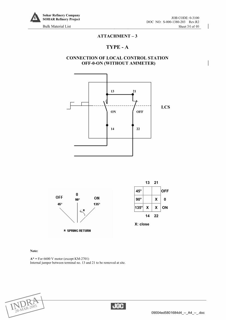
JOB CODE: 0-3100Sohar Refinery Company SOHAR Refinery Project
DOC NO: S-000-1380-203 Rev.R2 Bulk Material List Sheet 34 of 46
09004ed5801684d4_--_A4_--_.doc
ATTACHMENT – 3
TYPE - A
CONNECTION OF LOCAL CONTROL STATION OFF-0-ON (WITHOUT AMMETER)
Note: A* = For 6600 V motor (except KM-2701) Internal jumper between terminal no. 13 and 21 to be removed at site.
13 21
45° OFF
90° X 0
135° X X ON
14 22
X: close
13 21
14 22
LCS OFFON
_____
| |
| |
_____INDRA
28-MAR-2005

JOB CODE: 0-3100Sohar Refinery Company SOHAR Refinery Project
DOC NO: S-000-1380-203 Rev.R2 Bulk Material List Sheet 35 of 46
09004ed5801684d4_--_A4_--_.doc
ATTACHMENT – 4
TYPE - B
CONNECTION OF LOCAL CONTROL STATION OFF-0-ON (WITH AMMETER)
Note: B* = For 6600 V motor (except KM-3202A/B) Internal jumper between terminal no. 13 and 21 to be removed at site.
13 21
45° OFF
90° X 0
135° X X ON
14 22
X: close
13 21
14 22
LCS OFFON
A (WITH AMMETER)
_____
| |
| |
_____INDRA
28-MAR-2005

JOB CODE: 0-3100Sohar Refinery Company SOHAR Refinery Project
DOC NO: S-000-1380-203 Rev.R2 Bulk Material List Sheet 36 of 46
09004ed5801684d4_--_A4_--_.doc
ATTACHMENT – 5
TYPE - C
CONNECTION OF LOCAL CONTROL STATION OFF – 0 – ON (WITHOUT AMMETER)
2 4 6
45° X OFF
90° X 0
135° X X ON
1 3 5
X: close
2 4
1 53
6
LCS
OFF 0 ON
_____
| |
| |
_____INDRA
28-MAR-2005

JOB CODE: 0-3100Sohar Refinery Company SOHAR Refinery Project
DOC NO: S-000-1380-203 Rev.R2 Bulk Material List Sheet 37 of 46
09004ed5801684d4_--_A4_--_.doc
ATTACHMENT – 6
TYPE - D
CONNECTION OF LOCAL CONTROL STATION OFF – 0 - ON (WITHOUT AMMETER)
2 4 6
45° OFF
90° X X 0
135° X X X ON
1 3 5
X: close
4 6
31 5
2
LCS
0 ONOFF
_____
| |
| |
_____INDRA
28-MAR-2005

JOB CODE: 0-3100Sohar Refinery Company SOHAR Refinery Project
DOC NO: S-000-1380-203 Rev.R2 Bulk Material List Sheet 38 of 46
09004ed5801684d4_--_A4_--_.doc
ATTACHMENT – 7
TYPE - E
CONNECTION OF LOCAL CONTROL STATION OFF – 0 - ON (WITH AMMETER)
2 4 6
45° OFF
90° X X 0
135° X X X ON
1 3 5
X: close
A (WITH AMMETER)
4 6
31 5
2
LCS
0 ONOFF
_____
| |
| |
_____INDRA
28-MAR-2005

JOB CODE: 0-3100Sohar Refinery Company SOHAR Refinery Project
DOC NO: S-000-1380-203 Rev.R2 Bulk Material List Sheet 39 of 46
09004ed5801684d4_--_A4_--_.doc
ATTACHMENT – 8
TYPE - F
CONNECTION OF LOCAL CONTROL STATION OFF – 0 – ON, OFF-ON (WITHOUT AMMETER)
2 4 6
45° X OFF
90° X 0
135° X X ON
1 3 5
X: close
8 10
45° X OPEN
135° X CLOSE
7 9
X: close
2 4
1 53
6
LCS
OFF 0 ON
8 10
7 9
OPEN CLOSE
_____
| |
| |
_____INDRA
28-MAR-2005

JOB CODE: 0-3100Sohar Refinery Company SOHAR Refinery Project
DOC NO: S-000-1380-203 Rev.R2 Bulk Material List Sheet 40 of 46
09004ed5801684d4_--_A4_--_.doc
ATTACHMENT – 9
TYPE - G
CONNECTION OF LOCAL CONTROL STATION OFF-0-ON (WITHOUT AMMETER)
13 21
45° X OFF
90° 0
135° X ON
14 22
X: close
13 21
14 22
LCS OFFON
_____
| |
| |
_____INDRA
28-MAR-2005

JOB CODE: 0-3100Sohar Refinery Company SOHAR Refinery Project
DOC NO: S-000-1380-203 Rev.R2 Bulk Material List Sheet 41 of 46
09004ed5801684d4_--_A4_--_.doc
ATTACHMENT – 10
TYPE – H
CONNECTION OF LOCAL CONTROL STATION OFF – 0 - ON (WITHOUT AMMETER)
2 4 6
45° OFF
90° X 0
135° X X X ON
1 3 5
X: close
4 6
31 5
2
LCS
0 ONOFF
_____
| |
| |
_____INDRA
28-MAR-2005

JOB CODE: 0-3100Sohar Refinery Company SOHAR Refinery Project
DOC NO: S-000-1380-203 Rev.R2 Bulk Material List Sheet 42 of 46
09004ed5801684d4_--_A4_--_.doc
ATTACHMENT – 11
TYPE - I
CONNECTION OF LOCAL CONTROL STATION OFF – 0 – ON (WITHOUT AMMETER)
2 4 6
45° X OFF
90° X 0
135° X X ON
1 3 5
X: close
2 4
1 53
6
LCS
OFF 0 ON
_____
| |
| |
_____INDRA
28-MAR-2005

JOB CODE: 0-3100Sohar Refinery Company SOHAR Refinery Project
DOC NO: S-000-1380-203 Rev.R2 Bulk Material List Sheet 43 of 46
09004ed5801684d4_--_A4_--_.doc
ATTACHMENT – 12
2-POLE TUMBLER SWITCH (ON/OFF)
2 4
45° OFF
135° X X ON
1 3
X: close
2 4
1 3
45ο 135οOFF ON
_____
| |
| |
_____INDRA
28-MAR-2005

JOB CODE: 0-3100Sohar Refinery Company SOHAR Refinery Project
DOC NO: S-000-1380-203 Rev.R2 Bulk Material List Sheet 44 of 46
09004ed5801684d4_--_A4_--_.doc
ATTACHMENT – 13
4-POLE TUMBLER SWITCH (ON/OFF)
2 4 6 8
45° OFF
135° X X X X ON
1 3 5 7
X: close
2 4
1 3
6
5
8
7
45ο 135οOFF ON
_____
| |
| |
_____INDRA
28-MAR-2005

JOB CODE: 0-3100Sohar Refinery Company SOHAR Refinery Project
DOC NO: S-000-1380-203 Rev.R2 Bulk Material List Sheet 45 of 46
09004ed5801684d4_--_A4_--_.doc
ATTACHMENT – 14
NAMEPLATE DIMENSIONS
_____
| |
| |
_____INDRA
28-MAR-2005

JOB CODE: 0-3100Sohar Refinery Company SOHAR Refinery Project
DOC NO: S-000-1380-203 Rev.R2 Bulk Material List Sheet 46 of 46
09004ed5801684d4_--_A4_--_.doc
ATTACHMENT – 15 JUNCTION BOX LIST
Bottom Entry 1 Bottom Entry 2 Bottom Entry 3 Bottom Entry 4 Side Entry
JB No. Voltage (V)
Rated Current
(A)
Cable size
Cable Gland Size
Cable Size
Cable Gland Size
Cable Size
Cable Gland Size
Cable Size
Cable Gland Size
Cable Size
Cable Gland Size
V-1101A-JB 6600 32.8 3C-25* M50/71.5mm 3C-25* M50/71.5mm 3C-25* M50/71.5mm 3C-25* M50/71.5mm V-1101B-JB 6600 32.8 3C-25* M50/71.5mm 3C-25* M50/71.5mm 3C-25* M50/71.5mm 3C-25* M50/71.5mm 110WO401-JB 415 60 4C-70* M50S/71.5mm 4C-70* M50S/71.5mm 4C-25 M25/41.4mm110WO402-JB 415 60 4C-70* M50S/71.5mm 4C-70* M50S/71.5mm 4C-25 M25/41.4mm110WO403-JB 415 60 4C-70* M50S/71.5mm 4C-25 M25/41.4mm200WO401-JB 415 60 4C-50* M40/60.5mm 4C-50* M40/60.5mm 4C-25 M25/41.4mm200WO402-JB 415 60 4C-50* M40/60.5mm 4C-50* M40/60.5mm 4C-25 M25/41.4mm200WO403-JB 415 60 4C-50* M40/60.5mm 4C-25 M25/41.4mm200WO404-JB 415 60 4C-95* M50/71.5mm 4C-95* M50/71.5mm 4C-25 M25/41.4mm200WO405-JB 415 60 4C-95* M50/71.5mm 4C-95* M50/71.5mm 4C-25 M25/41.4mm200WO406-JB 415 60 4C-95* M50/71.5mm 4C-25 M25/41.4mm320WO401-JB 415 60 4C-50* M40/60.5mm 4C-50* M40/60.5mm 4C-25 M25/41.4mm320WO402-JB 415 60 4C-50* M40/60.5mm 4C-50* M40/60.5mm 4C-25 M25/41.4mm320WO403-JB 415 60 4C-50* M40/60.5mm 4C-25 M25/41.4mm330WO401-JB 415 60 4C-70* M50S/71.5mm 4C-70* M50S/71.5mm 4C-25 M25/41.4mm330WO402-JB 415 60 4C-70* M50S/71.5mm 4C-70* M50S/71.5mm 4C-25 M25/41.4mm330WO403-JB 415 60 4C-70* M50S/71.5mm 4C-25 M25/41.4mm280WO401-JB 415 60 4C-70* M50S/71.5mm 4C-70* M50S/71.5mm 4C-25 M25/41.4mm280WO402-JB 415 60 4C-70* M50S/71.5mm 4C-70* M50S/71.5mm 4C-25 M25/41.4mm280WO403-JB 415 60 4C-70* M50S/71.5mm 4C-25 M25/41.4mm500WO401-JB 415 60 4C-25 M25/41.4mm 4C-25 M25/41.4mm500WO404-JB 415 60 4C-70 M40/60.5mm 4C-70 M40/60.5mm 4C-25 M25/41.4mm500WO405-JB 415 60 4C-70 M40/60.5mm 4C-70 M40/60.5mm 4C-25 M25/41.4mm500WO406-JB 415 60 4C-70 M40/60.5mm 4C-25 M25/41.4mm500WO407-JB 415 60 4C-50 M32/50.6mm 4C-50 M32/50.6mm 4C-25 M25/41.4mm500WO408-JB 415 60 4C-50 M32/50.6mm 4C-25 M25/41.4mm610WO401-JB 415 60 4C-70 M40/60.5mm 4C-25 M25/41.4mm610WO402-JB 415 60 4C-70 M40/60.5mm 4C-25 M25/41.4mm650WO401-JB 415 60 4C-50 M32/50.6mm 4C-50 M32/50.6mm 4C-25 M25/41.4mm650WO402-JB 415 60 4C-50 M32/50.6mm 4C-50 M32/50.6mm 4C-25 M25/41.4mm650WO403-JB 415 60 4C-50 M32/50.6mm 4C-25 M25/41.4mm620WO401-JB 415 60 4C-50 M32/50.6mm 4C-25 M25/41.4mm620WO402-JB 415 60 4C-95 M40/60.5mm 4C-95* M50/71.5mm 4C-25 M25/41.4mm620WO403-JB 415 60 4C-95* M50/71.5mm 4C-25 M25/41.4mm620WO404-JB 415 60 4C-35 M32/50.6mm 4C-25 M25/41.4mm620WO405-JB 415 60 4C-70 M40/60.5mm 4C-70 M40/60.5mm 4C-25 M25/41.4mm620WO406-JB 415 60 4C-70 M40/60.5mm 4C-70 M40/60.5mm 4C-25 M25/41.4mm620WO407-JB 415 60 4C-70 M40/60.5mm 4C-25 M25/41.4mm380WO401-JB 415 60 4C-70 M40/60.5mm 4C-70 M40/60.5mm 4C-25 M25/41.4mm630WO401-JB 415 60 4C-70 M40/60.5mm 4C-25 M25/41.4mm640WO401-JB 415 60 4C-50 M32/50.6mm 4C-50 M32/50.6mm 4C-25 M25/41.4mm640WO402-JB 415 60 4C-50 M32/50.6mm 4C-25 M25/41.4mm
NOTE: * - Lead sheath cable
_____
| |
| |
_____INDRA
28-MAR-2005

09004ed58010e4cc_--_A4_--_.doc
JOB No. JGC DOC. No. REV.
0-3100-25 S-000-1380-001 R2
DATE 7 − Oct − 2003 SHEET 1 OF 38 PREP’D A. Chikuzaki
CHK’D S.Shimoi
APP’D Y.Akashi
GENERAL SPECIFICATION FOR
ELECTRICAL FACILITIES
SOHAR REFINERY COMPANY L. L. C.
SOHAR REFINERY PROJECT
SOHAR, SULTANATE OF OMAN
Reference ITT Doc. No. Rev
S-000-1380-001 C
REV. DATE PAGE DESCRIPTION PREP’D CHK’D APP’D
0 29 Jul 2003 All For approval SS SS YA
R 7 Oct 2003 All For construction AC SS YA
R1 8 Dec 2003 All For construction (as per OY-JY-E-20746 and
OY-JY-E-20969)
AC SS YA
R2 25 Nov 2004 All For construction AC SS YA
PROJECT SPECIFICATION
Sohar Refinery Company
SOHAR Refinery Project
FOR CONSTRUCTION
_____
| |
| |
_____INDRA
07-DEC-2004

JOB CODE: 0-3100Sohar Refinery Company SOHAR Refinery Project
DOC NO: S-000-1380-001 rev.R2 General Specification for Electrical Facilities SHEET : 2 of 38
09004ed58010e4cc_--_A4_--_.doc
CONTENTS
1 INTRODUCTION .............................................................................................................................................. 5 2 CODES AND STANDARDS.............................................................................................................................. 5 3 LANGUAGE AND SYSTEM OF UNIT........................................................................................................... 5 4 SITE CONDITIONS (DESIGN BASE) ............................................................................................................ 6 5 GENERAL .......................................................................................................................................................... 6 6 AREA CLASSIFICATION ................................................................................................................................ 7 7 DESIGN CRITERIA.......................................................................................................................................... 8
7.1 General ................................................................................................................................................... 8 7.2 Protection Relaying ............................................................................................................................... 9 7.3 Voltage System ....................................................................................................................................... 9 7.4 Harmonic Distortion and Electromagnetic Compatibility (EMC).................................................. 11 7.5 Allowable Voltage Drop....................................................................................................................... 11 7.6 Supply Capacity................................................................................................................................... 12 7.7 Transformer Sizing.............................................................................................................................. 12 7.8 Cable Sizing.......................................................................................................................................... 12 7.9 Local Isolator ....................................................................................................................................... 13
8 POWER SOURCES ......................................................................................................................................... 13 8.1 General ................................................................................................................................................. 13 8.2 Power Station ....................................................................................................................................... 13 8.3 Diesel Engine GEN SET...................................................................................................................... 14 8.4 Tie-in for Power Import/Export ......................................................................................................... 14 8.5 Instrument, Communication and Electrical System Monitoring Power Supply............................ 15
9 POWER DISTRIBUTION SYSTEM ............................................................................................................. 16 10 Operation ........................................................................................................................................................ 17
10.1 Power Management System (PMS)..................................................................................................... 18 11 AREA SUBSTATION REQUIREMENTS.................................................................................................... 18
11.1 Substation House ................................................................................................................................. 18 11.2 Surroundings........................................................................................................................................ 18 11.3 Doors and Aprons ................................................................................................................................ 19 11.4 Pressurizing, and Air Conditioning.................................................................................................... 19 11.5 Transformer Yard................................................................................................................................ 19 11.6 Equipment Layout and Clearances.................................................................................................... 20
12 ELECTRICAL EQUIPMENT AND MATERIALS .................................................................................... 20 12.1 General ................................................................................................................................................. 20 12.2 Alternator............................................................................................................................................. 21
_____
| |
| |
_____INDRA
07-DEC-2004

JOB CODE: 0-3100Sohar Refinery Company SOHAR Refinery Project
DOC NO: S-000-1380-001 rev.R2 General Specification for Electrical Facilities SHEET : 3 of 38
09004ed58010e4cc_--_A4_--_.doc
12.3 Transformers........................................................................................................................................ 21 12.4 Electrical Motors ................................................................................................................................. 22 12.5 145 kV (132 kV use ) Electrical Equipment....................................................................................... 22 12.6 Medium Voltage Switchgear (33 kV and 6.6kV except outdoor type )............................................ 22 12.7 Low Voltage Switchgear...................................................................................................................... 23 12.8 Controlgear .......................................................................................................................................... 23 12.9 DC System............................................................................................................................................ 23 12.10 AC Uninterruptible Power Supply System (UPS) ........................................................................ 24 12.11 Power Factor Correction Equipment............................................................................................. 24
13 CABLE INSTALLATION ............................................................................................................................. 24 13.1 General ................................................................................................................................................. 24 13.2 Underground Cable Installation ........................................................................................................ 24 13.3 Above Grade Cable Installation......................................................................................................... 25 13.4 Duct Bank System................................................................................................................................ 26 13.5 Types of Cable...................................................................................................................................... 26 13.6 Cable Size ............................................................................................................................................. 27 13.7 Cable Termination ............................................................................................................................... 27 13.8 Colour Identification ........................................................................................................................... 27
14 EARTHING AND LIGHTNING PROTECTION ....................................................................................... 28 14.1 General ................................................................................................................................................. 28 14.2 Earth Network ..................................................................................................................................... 28 14.3 Electrical System Earth....................................................................................................................... 28 14.4 Earth Connection and Bonding (Equipment Earth) ........................................................................ 29 14.5 Earth Electrode.................................................................................................................................... 29 14.6 Lightning Protection............................................................................................................................ 30 14.7 Instrument Earth System.................................................................................................................... 30
15 LIGHTING SYSTEM AND SOCKET OUTLET........................................................................................ 30 15.1 General ................................................................................................................................................. 30 15.2 Local Lighting Distribution Boards ................................................................................................... 31 15.3 Branch Circuits.................................................................................................................................... 31 15.4 Lighting Fixtures Application............................................................................................................. 32 15.5 Road and Perimeter Fence Lighting .................................................................................................. 33 15.6 Emergency Lighting ............................................................................................................................ 33 15.7 Aircraft Warning Light....................................................................................................................... 33 15.8 Illumination Level ............................................................................................................................... 33 15.9 Receptacles ........................................................................................................................................... 33 15.10 Illumination Levels .......................................................................................................................... 34
_____
| |
| |
_____INDRA
07-DEC-2004

JOB CODE: 0-3100Sohar Refinery Company SOHAR Refinery Project
DOC NO: S-000-1380-001 rev.R2 General Specification for Electrical Facilities SHEET : 4 of 38
09004ed58010e4cc_--_A4_--_.doc
16 CATHODIC PROTECTION......................................................................................................................... 36 17 COMMUNICATION ..................................................................................................................................... 36
ATTACHMENT “A” ....................................................................................................................................... 38
_____
| |
| |
_____INDRA
07-DEC-2004

JOB CODE: 0-3100Sohar Refinery Company SOHAR Refinery Project
DOC NO: S-000-1380-001 rev.R2 General Specification for Electrical Facilities SHEET : 5 of 38
09004ed58010e4cc_--_A4_--_.doc
1 INTRODUCTION 1.1 This specification describes minimum requirements for the electrical system design, installation,
equipment and materials for the Sohar Refinery Project of Sohar Refinery Company L.L.C. in Sultanate of Oman.
1.2 In addition to this general specification, detailed specifications shall be prepared for major electrical
equipment. 1.3 All documents with F-WBS code 138X (Refer to Numbering Procedure S-000-1140-101) are applied
together with this specification: 2 CODES AND STANDARDS 2.1 General
The equipment, materials, design and installation of the electrical facilities shall conform to the local law and regulation and the applicable portions of the latest edition of standards as of 19-May-2003.
2.2 Laws and Regulations
Country, OMAN, laws and regulations for electrical equipment and installation.
2.3 Standards
(1) For design, manufacturing, test and installation. - International Electrotechnical Commission (IEC) - Country standards of Sultanate of Oman Refer to ATTACHMENT “A”. (2) For equipment and material selection, any other national standards may also be acceptable
subject to the approval of the Owner. (3) For area classification and selection of electrical equipment to be installed in hazardous areas,
codes and standards relating the hazardous area and equipment selection are specified in Paragraph 6.
2.4 Order of Precedence for Documents
Country laws and regulations Project specifications and drawings IEC and internationally recognized standards Country standards of OMAN (Only for applicable to tie-in points of 132 kV grid)
3 LANGUAGE AND SYSTEM OF UNIT Documents, drawings, data, etc. shall be in the English Language. Metric system shall be applied, except
for the nominal size of conduit pipes. If foot-inch unit are used, metric unit should be stated together.
_____
| |
| |
_____INDRA
07-DEC-2004

JOB CODE: 0-3100Sohar Refinery Company SOHAR Refinery Project
DOC NO: S-000-1380-001 rev.R2 General Specification for Electrical Facilities SHEET : 6 of 38
09004ed58010e4cc_--_A4_--_.doc
4 SITE CONDITIONS (DESIGN BASE) 4.1 Altitude : Less than 1,000m above sea level 4.2 Ambient Temperature
Minimum recorded : 3.5 °C Maximum recorded : 47.5 °C
Design temperature for electrical equipment for indoor with air conditioner : 5 to 40 Design temperature for electrical equipment for outdoor : 5 to 42 4.3 Relative Humidity
Relative humidity (maximum) : 100 % Relative humidity (minimum) : 6 %
Out door electrical equipment shall be designed based on 100% of relative humidity 4.4 Max. wind velocity for design
22.9 m/sec
Design shall include any direction of wind force. 4.5 Earthquake : Nil
5 GENERAL
5.1 Operational Safety, Reliability and Availability
The electrical engineering design shall be based on the requirement to provide a safe and reliable supply of electricity to all users. The design shall ensure that safe conditions exist under all operating conditions, including those associated with start-up and shutdown of plant and equipment. The design shall ensure that all maintenance activities can be performed safely and conveniently and that periods of continuous operation can be for at least 4 years. To meet these requirements, provision will be made for alternative supply sources and cable routes, spare/standby capacity, load shedding, automatic transfer of switchboard bus bars and motor restarting schemes. Adequate access to equipment will be provided for all operational and maintenance purposes. The simultaneous failure of two pieces of equipment shall not be catered for. The electrical power system shall have a degree of reliability commensurate with the required services and load classification as specified in Para. 9.5. The reliability of distribution system shall be at least comparable to their supply systems, each incorporating sufficient standby capacity to enable maintenance work, tests and inspection checks to be carried out. Electrical system maintenance requirements shall be considered in relation to plant
_____
| |
| |
_____INDRA
07-DEC-2004

JOB CODE: 0-3100Sohar Refinery Company SOHAR Refinery Project
DOC NO: S-000-1380-001 rev.R2 General Specification for Electrical Facilities SHEET : 7 of 38
09004ed58010e4cc_--_A4_--_.doc
shutdown for overhaul of process units. For critical loads a complete duplication of the energy source, the lines of supply and the equipment is necessary. Single circuits are not acceptable as means of supplying critical and vital loads. Electricity supplies of enhanced reliability and having duplicate energy sources shall be provided to energize loads forming part of critical services. Such supplies shall, if required by the load, be uninterrupted on failure of one energy source. Loads which can tolerate an interruption in the power supply but which require restoration of the supply within a relatively short period of time shall be energized from an interruptible maintained power source. For vital loads and essential loads a complete duplication or partial duplication (n + 1 approach) of the energy source, the lines of supply, the electrical equipment and the introduction of automatic changeover for power distribution equipment and restarting facilities shall be provided. Single circuits shall only be considered for non-essential loads. The insulating and dielectric materials used in all electrical equipment shall be non-toxic and shall not contain compounds that are persistent and/or hazardous environmental contaminants, for example polychlorinated biphenyls (PCBs).
5.2 Standardization
The electrical equipment shall be standardized as much as possible. Consideration should be given to install Zone 2 materials and Zone 2 equipment such as lighting fixtures, control stations, socket outlets and junction boxes, except for the building facilities, also in unclassified areas within the process areas.
5.3 Equipment Lifetime Main equipment shall have a design lifetime of 20 years.
6 AREA CLASSIFICATION EPC Contractor shall develop Hazardous Area Classification drawings based on verified plot plan by
EPC Contractor in accordance with IEC 60079-10 and select any equipment in classified area in accordance with IEC 60079-14.
6.1 Area Classification Area classification shall be in accordance with Area Classification Code for Petroleum Installation IP part 15 and IEC60079-10.
6.2 Zones All areas within scope of Sohar Refinery Project, shall be classified as one of the following zones to define the design and installation requirements for electrical equipment and facilities:
(1) Zone 0
Area where an explosive gas atmosphere is present continuously or is present for long periods.
(2) Zone 1
Area where an explosive atmosphere is likely to occur in normal operation.
_____
| |
| |
_____INDRA
07-DEC-2004

JOB CODE: 0-3100Sohar Refinery Company SOHAR Refinery Project
DOC NO: S-000-1380-001 rev.R2 General Specification for Electrical Facilities SHEET : 8 of 38
09004ed58010e4cc_--_A4_--_.doc
(3) Zone 2
Area where an explosive gas atmosphere is not likely to occur in normal operation, if it occurs, will exist only for a short period.
(4) Natural Non-hazardous
A location considered inherently non-hazardous due to its separation from hazardous locations.
6.3 Equipment Selection
(1) Electrical equipment to be used in classified areas shall be selected in accordance with IEC 60079 - 14.
(2) Electrical equipment in hazardous location shall be certified by the authorities such as:
ISSEP : Belgium EECS, SCS : Great Britain PTB, BVS : Germany LCIE, INERIS : France CESI : Italy LOM : Spain KEMA : Netherlands TIIS : Japan UL, FM : USA Note CSA : Canada Note
Note : Products in accordance with ANSI/NEMA standards to be installed at Hazardous area,
shall be approved by Owner unless otherwise specified. 6.4 Combustible dusts
The area classification, presence of combustible dusts, shall be developed by Contractor, the area classification drawings and material selection shall be a subject of Owner approval. The followings are applicable standards. (1) IEC 61241 (2) BS 7535-1992
ELECTRICAL APPARATUS complying with BS 5501 or BS 6941 in the presence of combustible dusts
(3) NFPA 499
Recommended Practice for the Classification of Combustible Dusts and Hazardous (classified) Locations for Electrical Installations in Chemical Process Area.
7 DESIGN CRITERIA
7.1 General
The design of the electrical system shall be carried out in accordance with the Key One Line Diagram with the following clarifications.
_____
| |
| |
_____INDRA
07-DEC-2004

JOB CODE: 0-3100Sohar Refinery Company SOHAR Refinery Project
DOC NO: S-000-1380-001 rev.R2 General Specification for Electrical Facilities SHEET : 9 of 38
09004ed58010e4cc_--_A4_--_.doc
7.2 Protection Relaying
The protective devices throughout the system shall be coordinated to allow sensitive fault detection, to
trip selectively and to isolate faulted equipment in order to minimize disturbances to power supply. 7.3 Voltage System
The power generation and distribution throughout the plant shall be 50 Hz, at the following voltage
levels with earthing system:
_____
| |
| |
_____INDRA
07-DEC-2004

JOB CODE: 0-3100Sohar Refinery Company SOHAR Refinery Project
DOC NO: S-000-1380-001 rev.R2 General Specification for Electrical Facilities SHEET : 10 of 38
09004ed58010e4cc_--_A4_--_.doc
Power Generation and Distribution System
Service System Voltage
(No-load Voltage) (V)
Rated Voltage (User Voltage)
(V)
Fault Level (kA)
(see Note)
Phase/Wire Earthing
Power Generation 11,000 (AVR control )
11,000 31.5/3 sec. 3/3 Earthing transformer
Power export (Tie in to grid station)
132,000 (CB Rated 145 kV)
132,000 40/3 sec 3/3 Solid
Main power distribution 34,500 (CB Rated 36 kV)
33,000 (normal
operation)
40/3 sec 3/3 High Resistance earthing
(200A, 30sec.)Sub-distribution and large capacity motors
6,900 6,600 31.5/3 sec 3/3 High Resistance earthing
(400A, 10sec.)Small power distribution standard size motor Lighting and Misc.
433/250 433
433/250
415/240 415
415/240
40-23/ 1 sec 40-23/ 1 sec
3/4 3
3/4
Solid
Emergency power Generator (AVR control) Distribution
Large KVA Small KVA
UPS system
6,600
6,900
433/250
n/a.
6,600
415/240
31.5/3 sec
3/3
High Resistance earthing
(400A, 10sec.)
AC system(UPS) for DCSAC system (UPS) for
communication
__
__
240
240
*1
*1
1/2
1/2
Solid
Non-earthed DC system (UPS) for
Substation Equipment Control
__ 110 less than 1 DC Non-earthed
DC system (UPS) for communication
__ 110/48 less than 2 DC Non-earthed
Note : The fault levels shown are preliminary. These are the expected Maximum values and are subject to
be ensured during detailed design.
For installations above 1000V, the short circuit contributions from all supplies which can be operated in parallel shall include contributions via bus section switches or interconnectors which are capable of being operated simultaneously in the closed position. This includes bus section switches or interconnectors, etc., which are intended for normally open operation and on which no interlocking has been provided to prevent simultaneous closure. For LV switchboards equipped with multiple transformer incomers and / or generator incomers, the short circuit rating of LV switchboards may be based on the number of permanently connected incoming feeders, provided that the remainder of the incoming LV feeders shall be equipped with automatic disconnecting logic circuitry ensuring that paralleling operation of all LV infeeds over max. 5 seconds is not possible. For installations above 1000V, automatic break-before-make changeover arrangements of supply capacity shall not be introduced with the specific aim of justifying the use of equipment having a lower short circuit rating than would otherwise be required when based on the parallel operation of all available supplies.
*1: The fault rating of the AC UPS system shall be taken account of the contribution via the static and /
or maintenance bypass, and also taken account of consideration of the batteries.
_____
| |
| |
_____INDRA
07-DEC-2004

JOB CODE: 0-3100Sohar Refinery Company SOHAR Refinery Project
DOC NO: S-000-1380-001 rev.R2 General Specification for Electrical Facilities SHEET : 11 of 38
09004ed58010e4cc_--_A4_--_.doc
Motors and other users rated voltage and phase shall be as follows:
Service Rated Voltage (V) (User Voltage) Phase/Wire
Motors 3000 kW and above * 3/3 Motors over 150 kW ~ less 3000 kW 6,600 3/3 Motors over 0.75 kW ~ up to 150 kW 415 3/3 Motors up to 0.75 kW ** 240/415 1/2, 3/3 Lighting fixtures 240 1/2 Power (welding) 415/240 3/4+Earthing Convenience receptacles 240 1/2+Earthing Control circuits 33 kV and 6.6 kV Switchgear control 110 DC 6.6 kV motor starters control 240 1/2 LV Switchgear control 110 DC LV motor starters control 240 1/2 132 kV Switchgear control 110 DC Steam turbine GEN SET control 110 DC Gas turbine GEN SET control Gas turbine GEN SET (cooling down)
110 ***
DC DC
PMS 110 DC Communication 240
110/48 1/2 DC
Note * : Motors voltage for 3000 kW and over shall be selected during detailed design stage,
individually. Note ** : Motors for up to 0.75 kW, will be single phase 240 V 50 Hz for non-hazardous area, and
3 phase 415V 50Hz will be for hazardous area. Note***: The Generator Set supplier should provide a recommended nominal voltage for this system.
7.4 Harmonic Distortion and Electromagnetic Compatibility (EMC)
The harmonic distortion and electromagnetic compatibility (EMC) shall be considered in accordance with IEC 61000 and IEEE 519.
7.5 Allowable Voltage Drop
The maximum allowable voltage drops in cables during stable conditions, as a percentage of against system voltage at rated load, shall be as follows: (1) 33kV and 6.6 kV power distribution : 2 % *
6,600 volt motors : 5.0 % 415/240 volt power distribution : 2 % * 415 volt motors : 5.0 %
* Note : When captive transformer or other voltage adjustment devices are provided, these values will be rectified.
_____
| |
| |
_____INDRA
07-DEC-2004

JOB CODE: 0-3100Sohar Refinery Company SOHAR Refinery Project
DOC NO: S-000-1380-001 rev.R2 General Specification for Electrical Facilities SHEET : 12 of 38
09004ed58010e4cc_--_A4_--_.doc
(2) Total voltage drop at the terminal of low voltage motor shall not exceed 20 % during starting period.
(3) Transient voltage deviations occurring at switchgear bus bars during motor or group motor
starting / re-acceleration shall be such as to maintain a minimum of 90% voltage on switchgear bus bars, and at least 80%, but not more than 110%, of rated equipment voltage on all other consumers.
(4) Voltage drop between lighting panelboard and the farthest fixture shall not exceed 3 %.
The voltage at lighting fixture shall be within -5% against rated voltage during plant stable operation.
(5) The voltage drop from the consumer’s main board to any point in his installation shall not
exceed 2.5% of the rated service voltage when all the conductors in the installation are carrying the maximum current.
7.6 Supply Capacity
(1) Power Generation Main power at the site will be generated by gas and steam turbine driven generators. The
number of gas and steam turbine driven generators is 4 operation basis. (2) Electrical Power Distribution
In general all substations shall be sized for the maximum operation loads plus 20 percent spare capacity to be available at Mechanical Completion.
7.7 Transformer Sizing
(1) The distribution transformers shall be sized to supply for the maximum demand of load
connected to the associated switchgear plus 20% spare capacity for future expansion at ambient temperature. The maximum demand of loads shall be calculated by considering intermittent loads.
(2) The transformer kVA rating shall be chosen as far as possible in accordance with the standard
sizes as per IEC 60076 recommendation. (3) The maximum capacity of 433V transformer shall be limited up to 2000kVA. (4) Distribution transformers rated 750 kVA and above shall be sized at ONAN rating and shall
have a future provision of cooling fans for additional loads in future.
7.8 Cable Sizing
The cable shall be sized based on the thermal limits in normal service conditions, and the maximum allowable voltage drops in the circuit. The current carrying capacity (thermal limit) of cables in normal service conditions shall take into account the de-rating due to the laying conditions or grouping. The soil thermal resistance shall be considered for cable size selection. The cables for main power distribution system shall be sized also to withstand against the maximum short circuit thermal stress for the full clearance time of the protective devices (i.e. fuses, or circuit breakers with protection relays). In case of LV cables protected by MCCB, the LV cables shall be sized to withstand the maximum short circuit thermal stress at load end or intermediate fault.
_____
| |
| |
_____INDRA
07-DEC-2004

JOB CODE: 0-3100Sohar Refinery Company SOHAR Refinery Project
DOC NO: S-000-1380-001 rev.R2 General Specification for Electrical Facilities SHEET : 13 of 38
09004ed58010e4cc_--_A4_--_.doc
The current rating of the circuit for cable sizing shall be as follows:
(1) The transformer primary and secondary cables shall be rated based on a current equal to the rated
current of the transformer and suitable for future provision of forced air cooling rating. (2) The cables to switchgear and/or panel boards without step down transformer shall have a current
carrying capacity equal to the maximum demand of loads connected to the switchgear/panel board.
(3) The motor feeder cables shall be sized based on the 100% of motor nameplate rated current. (4) All the remaining cables not mentioned above shall have a current carrying capacity equal to the
maximum current demand of continuous duration. The cables for analogue signals shall be in accordance with BS5308 part 2.
7.9 Local Isolator
Motors shall be equipped with local isolators or equivalent means such as local control stations with padlock facilities in the off position. Motors which are mounted above grade and controlled from grade level for operational convenience, shall have safety switches/isolators located near the motor. Where motors are fitted with anti-condensation heaters, a heaters safety switch shall be installed adjacent to the motor remote control unit. Local isolators shall have padlock facilities in the off mode.
8 POWER SOURCES
8.1 General
The electrical power sources are consisting of the following facilities.
8.2 Power Station
Power station located in the refinery shall be composed with two gas turbine GEN SETs and two steam turbine GEN SETs. The units shall be both island operation and parallel operation with each other and/or with grid station.
(1) Gas turbine GEN SET each, continuous operation ratings based on ISO standard reference
conditions. Rated voltage : 11,000 V Rated frequency : 50 Hz Rated out put : 20 MW, pf = 0.85 Phase : 3 phase Neutral earthing : Hi-resistor earthing Unit transformer (step-up) Rated capacity : 25 MVA, self cooling Rated voltage : 11,000 / 34,500 V Connection : Delta / Star, Neutral lead out Neutral earthing : Resistor earthing
(2) Steam turbine GEN SET, continuous operation ratings based on ISO standard reference conditions. Rated voltage : 11,000 V
_____
| |
| |
_____INDRA
07-DEC-2004

JOB CODE: 0-3100Sohar Refinery Company SOHAR Refinery Project
DOC NO: S-000-1380-001 rev.R2 General Specification for Electrical Facilities SHEET : 14 of 38
09004ed58010e4cc_--_A4_--_.doc
Rated frequency : 50 Hz Rated out put : 40 MW, pf=0.85 Phase : 3 phase Neutral earthing : Hi-resistor earthing
Unit transformer (step-up) Rated capacity : 50 MVA, self cooling Rated voltage : 11,000 / 34,500 V Connection : Delta / Star, Neutral lead out Neutral earthing : Resistor earthing
8.3 Diesel Engine GEN SET
One diesel engine GEN SET shall be provided at main substation. The unit shall be applied for Gas turbine GEN SET start-up and supply the emergency power when total power failure occurred. The unit shall be normally cold stand-by and be started automatically when it detects the power failure. The generated electrical power shall be distributed to each user through independent distribution network and switchboard. The unit shall be in island operation except restoring operation and periodical load test operation. The manual unit control facilities shall be provided for load test operation and restoring into normal operation. Automatic and manual voltage control device shall be provided. Auto to manual and vice versa, shall be bumpless. Diesel engine GEN SET, continuous operation ratings based on ISO standard reference conditions. Rated voltage : 6,600 V Rated frequency : 50 Hz Rated out put : 2,100 kW, pf = 0.80 Phase : 3 phase Neutral earthing : Hi-resistor earthing At least, following loads shall be considered to be connected to emergency power. Loads for personnel safety Loads to protect equipment and/or property Fire fighting facilities Instrument and monitoring power sources Substation control power sources Telecommunication power sources Emergency lighting fixtures Specified loads by laws and regulations Other loads specified on specifications and/or drawings
8.4 Tie-in for Power Import/Export
The generated electrical power at power station will be exported through the tie in power lines. The tie in works and scope are as follows: Tie-in voltage : 132 kV (MAX. 145kV) Tie-in capacity : 70 MW, for export. Tie-in location : At the 132kV cable heads in the 132kV Switchyard near Main
Sub-station. Tie-in transformers (step-up)
_____
| |
| |
_____INDRA
07-DEC-2004

JOB CODE: 0-3100Sohar Refinery Company SOHAR Refinery Project
DOC NO: S-000-1380-001 rev.R2 General Specification for Electrical Facilities SHEET : 15 of 38
09004ed58010e4cc_--_A4_--_.doc
Rated Capacity : 75 MVA Rated Voltage : 33,000/132,000 V Connection : Star/Star with tertiary Delta winding (compensation) Neutral Earthing : Solid earthing at 132 kV side High resistance earthing (200A, 30sec.) at 33 kV side On load tap changer : Provided at 132 kV side with 26 taps (+10% to –15%) The export power (MW) and reactive power (MVAR) shall be controlled, monitored and recorded at main control room of the refinery, the lead power factor of export (MVA) shall be avoided. The following tie-in facilities to be provided 145 kV circuit breaker 145 kV isolator : To be included in GIS 145 kV CT : To be included in GIS 145 kV VT : To be included in GIS Associated 145kV GIS protection and control panel : To be provided The tariff metering and recording devices : Supply/installed by other The communication devices : Supply/installed by other 33/132 kV, 75 MVA tie-in step-up power transformer : To be provided Gantry tower : Supply/installed by other The technical parameters of grid station are; Voltage system : 132 kV AC, 50 Hz, 3 phase 3 wire, neutral solidly grounded. Voltage variation : +/- 5 % Frequency variation : +/- 2 % Short circuit capacity : 40 kA Required withstanding capacity second : 3 sec. The expected short time power failure due to the re-closing operation of grid station
: MAX. 3sec Estimated *
Note : Owner will specify during engineering stage.
The 132kV tie-in lines shall also be applied for power import in case of start up operation and emergency case. Contractor shall prepare the necessary document for Owner’s contract of power export and import.
8.5 Instrument, Communication and Electrical System Monitoring Power Supply
AC un-interruptible power supply system (UPS) with battery and battery supported DC unit shall be provided for essential instrumentation and other essential users. The followings to be provided as the minimum;
(1) DCS and ESD : 240 VAC UPS redundant units, battery
discharge time shall be 30 min. (2) Substation equipment control : 110 VDC single units, battery discharge time
shall be 4 hours. (3) Power station equipment control, monitoring and PMS : 240 VAC UPS redundant units, battery
discharge time shall be 8 hours. 110 VDC single units, battery discharge time
shall be 8 hours.
_____
| |
| |
_____INDRA
07-DEC-2004

JOB CODE: 0-3100Sohar Refinery Company SOHAR Refinery Project
DOC NO: S-000-1380-001 rev.R2 General Specification for Electrical Facilities SHEET : 16 of 38
09004ed58010e4cc_--_A4_--_.doc
Gas turbine cooling down facility * : DC single units, the Generator Set supplier should provide a recommended nominal voltage for this system.
(4) Communication power supply PBX and their control and recording ** : 48 VDC single units, battery discharge time
will be 12 hours Marine radio, ground to air radio and mobile radio for plant operation facilities: 240 VAC UPS redundant units, battery
discharge time will be 12 hours (5) Fire station monitoring facilities ** : Refer to Para. 3.9.1 of S-000-1371-002. (6) ICIMS servers, controllers *** : 240 VAC UPS redundant units, battery
discharge time will be 1 hours Note * : Voltage and discharge time shall be in accordance with manufacture recommendation. ** : Voltage and discharge time shall be in accordance with country standards or regulation. *** : Exclude the power for “Client PC”.
9 POWER DISTRIBUTION SYSTEM
The electrical power distribution system of Sohar Refinery Project is composed the power generators, tie in to Grid station and substations. The power generators consist of two gas turbine GEN SETs, two steam turbine GEN SETs and one diesel engine GEN SET. The diesel engine GEN SET shall be operated for gas turbine GEN SET start and emergency use. The main substation consists of two groups of 33 kV SWGR on which receive the generated power. It will be exported through two captive step-up transformers with on load tap changer (OLTC) and also be distributed to each area refinery substation by two separate underground cables. The main substation also covers the utility loads located in utility area and process loads in TAME / INALK unit with step-down distribution transformers to 6.6 kV and 415 V. The following area substations and electrical rooms shall be provided for power distribution: Area substation: Two substations for refinery process units One substation for tank area One substation for waste water treating facility One substation for sea water intake facility Electrical room The electrical room shall be provided for small power distribution on which 6.6 kV electrical power shall be distributed. One electrical room at jetty area with transformer yard One electrical room for main control building with transformer yard One electrical room for truck loading facilities with transformer yard One electrical room for administration building with transformer yard One electrical room for refinery maintenance area with transformer yard One electrical room for laboratory with transformer yard One electrical room for Canteen with transformer yard
9.1 Two groups of 33kV SWGR will always be set in parallel, except emergency and/or abnormal
_____
| |
| |
_____INDRA
07-DEC-2004

JOB CODE: 0-3100Sohar Refinery Company SOHAR Refinery Project
DOC NO: S-000-1380-001 rev.R2 General Specification for Electrical Facilities SHEET : 17 of 38
09004ed58010e4cc_--_A4_--_.doc
conditions. 9.2 The area substations shall be fed, separated but synchronized 33kV power, by two feeders.
The power shall be stepped down to 6.6kV for large capacity of loads and to 415V for small capacity of loads. Two incomers with tie breaker for 33kV power receiving shall be provided, where secondary selective system shall be provided. The tie breaker shall be normally open and will be closed automatically when one of two supplies is disturbed.
9.3 Power supply to electrical room will be by one feeder and/or separate two feeders in accordance with
load classification stated on Para.9.5.
9.4 The area substations shall be provided and located as close as possible to the electrical center of the loads of process units, utility facilities and off site facilities.
9.5 The electrical loads in the plant shall be classified as following categories.
Critical loads : Operation shall be personnel safety, protect equipment and property required by laws and regulation. Vital loads : Very essential for process operation.
Essential loads : Essential loads for process operation
Non essential : Non process load
The critical loads shall be provided stand-by machine which shall be supplied both electrical power, normal and emergency, and have a provision of re-starting and re-acceleration functions of their starters after power recovery. For Intelligent type control gear (IMCS) re-start and re-acceleration functions shall be included as far as possible in the micro-processor based motor protection units. Re-starting means : Starter shall be re-closed, after power recovery due to the short time power outage. Re-acceleration means : Load shall be re-accelerated after voltage recovery due to the voltage dip. Note : Voltage dip means voltage drop, but not outage. Voltage outage means power outage. Vital loads shall have a provision of stand-by machine which shall be supplied a power from different switchboard. The specified unit of vital loads shall have a provision of re-acceleration function for short time voltage dip. Essential loads may have a provision of stand-by machine which shall be connected to separate switchboard. Non essential load : Non process loads shall be classified as “Non essential“ unless
otherwise specified. Ring main distribution or radial distribution will be applied.
10 Operation
The study report for the cost effective and reliable mains generation and distribution system has been
_____
| |
| |
_____INDRA
07-DEC-2004

JOB CODE: 0-3100Sohar Refinery Company SOHAR Refinery Project
DOC NO: S-000-1380-001 rev.R2 General Specification for Electrical Facilities SHEET : 18 of 38
09004ed58010e4cc_--_A4_--_.doc
reported that the electric power energy for export will be generated by steam turbine and gas turbine generators utilized re-covered energy of refinery such as Off Gas and Generated steam.
The description of start-up, normal operation, failure situations for steam and gas turbine driven generator sets is given in the Operation Manual (Document Number later). Two gas turbine GEN SETs and two steam turbine GEN SETs shall be paralleled at 33 kV switchboard and with grid station through 132 kV tie-in lines. In principle, the steam turbine GEN SETs shall be operated at as close to their ratings as possible while gas turbine GEN SETs shall be running to maintain the frequency as required and their remaining power will be used as hot stand-by support to supply/absorb the necessary power demand fluctuations. The export power through 132 kV tie lines shall be controlled to maintain within the targeted range. The normal operation of these GEN SETs shall be performed from the control room in the main control building. The control panel located in SIH for each GEN SET shall be provided for individual unit operation.
10.1 Power Management System (PMS)
(1) The Power Management System (PMS) shall facilitate monitoring and control of the power generation
and distribution systems. The main purpose of the PMS shall be an aid to operations. Failure of the PMS shall not stop operation of any part of the power generation and distribution or interlock systems. Only facilities provided by PMS shall be lost in this case.
(2) The PMS shall interface with the power generation and distribution equipment including control panels of turbine generator sets and an emergency generator set, 145kV/33kV/6.6kV/415V switchgear, AC and DC UPS, on load tap changer control panels for tie-in transformers. Refer to General Specification Power Management System (PMS), S-000-1381-007 for the definition of requirements for network monitoring including interface list of metering, status, alarm, and shutdown signals.
(3) Operator consoles shall be installed in the control room of the Main Control Building.
11 AREA SUBSTATION REQUIREMENTS
11.1 Substation House
(1) Substations shall be single story construction with elevated floor of 1.5 m or more above the surrounding grade except electrical room that shall be in accordance with relevant specification.
(2) Substation house floors shall be finished smooth and levelled. Floor steel for mounting
switchgear and control equipment shall be levelled and installed flush with the finished grade unless otherwise specified in the relevant documents.
(3) Beneath of the substation floor shall be used for cable room and shall be surrounded by chain
link fence.
11.2 Surroundings
(1) Substations shall be located in unclassified areas away from the hazardous locations, free of cooling tower spray, and other gases or vapors which could cause deterioration of insulation and equipment failures.
_____
| |
| |
_____INDRA
07-DEC-2004

JOB CODE: 0-3100Sohar Refinery Company SOHAR Refinery Project
DOC NO: S-000-1380-001 rev.R2 General Specification for Electrical Facilities SHEET : 19 of 38
09004ed58010e4cc_--_A4_--_.doc
(2) The area surrounding substation shall be properly graded to divert the flow of surface water caused by the natural grade of the terrain. Substations shall not be located in low areas where surface water or hydrocarbons can accumulate.
(3) The substations shall be reasonably accessible for maintenance, and removal or addition of
major electrical equipment.
11.3 Doors and Platform
11.3.1 One (1) equipment door and one (1) personnel door shall be provided at the opposite side of the substation. The equipment door shall be of adequate size for equipment installation and removal.
11.3.2 The doors shall be arranged to be opened outward, and shall be fitted with locks. The
personnel doors shall be provided with a panic handle. 11.3.3 A platform with removable hand rail shall be installed in front of the equipment door to
facilitate equipment installation and removal. 11.3.4 For chain link fence of cable room, minimum two access gates with padlocks shall preferably
be provided on opposite sides.
11.4 Pressurizing, and Air Conditioning Air conditioning shall be provided to maintain the ambient temperature below to 40 Celsius and to
avoid a humidity condensation.
11.4.1 Substations located at non-hazardous area do not need to be pressurized. 11.4.2 In case where the substation is installed in hazardous areas, an air pressurizing system shall be
supplied to meet the requirements of special non-hazardous in accordance with the applicable standards or regulations.
11.5 Transformer Yard
11.5.1 Power transformers, neutral earthing resistor (NGR) and earthing transformer (GTR) where
required, shall be located outdoors. A dry type transformer may be installed in the substation house and/or electrical room.
11.5.2 Fire wall which is 2 hours proof against fire shall be provided in transformer yard between oil
immersed transformers and between transformer area and under floor area of the substation. 11.5.3 Transformers shall be located so that each transformer maintains the clearance, as well as that
the length and bends of the bus-ducts or cables can be minimized. 11.5.4 The foundations for transformers, NGR and GTR shall be at least 100 mm above the finished
grade of the transformer yard. 11.5.5 A chain link fence having 2400mm straight portion height only excluding inclined barbed wire
portion on top of it shall be provided around the perimeter of the transformer yard. Two access gates shall be provided on opposite sides of the yard. Gates shall have a provision for padlocking.
_____
| |
| |
_____INDRA
07-DEC-2004

JOB CODE: 0-3100Sohar Refinery Company SOHAR Refinery Project
DOC NO: S-000-1380-001 rev.R2 General Specification for Electrical Facilities SHEET : 20 of 38
09004ed58010e4cc_--_A4_--_.doc
11.6 Equipment Layout and Clearances
11.6.1 A common operating aisle is preferred for switchgear, control centers, distribution panels and other equipment. The panel front of equipment facing the common operation aisle shall be preferably arranged in line. Front and back clearance of such installation shall be decided based on the most stringent operation and maintenance requirements of the equipment in line.
11.6.2 Equipment shall be arranged so as to minimize cable crossing within the substation. 11.6.3 The minimum clearances of the equipment shall be in accordance with the manufacturer’s
recommendations but not less than the following criteria:
(1) Vertical, from the highest equipment including bus duct to : 500 mm ceiling or bottom of roof beam (2) Operation side of 33 kV switchgear : 2,500 mm 6.6 kV switchgear : 2,000 mm 415 V switchgear : 1,500 mm (3) Operation side of motor control centers and other panels : 1,500 mm (4) Side or rear (without access door) of switchgear, controlgear etc. : 600 mm This requirement is not applicable for front access construction panels (5) Rear with access door of switchgear, controlgear etc : 1,000 mm
11.6.4 Overlapping clearances, as in the aisle between switchgear and switchgear, or transformers,
are acceptable. 11.6.5 Minimum clearance measured from the furthest major projecting part of the transformer, such
as cable head, throat, or radiators shall be as follows:
(1) From house wall and fence : 1,000 mm min. (2) Between transformers : 1,500 mm min.
12 ELECTRICAL EQUIPMENT AND MATERIALS
12.1 General
12.1.1 The design shall be based on proper protection of personnel and equipment during operation and maintenance, reliability of service, ease of maintenance, the provision of future loads, and convenience of operation.
12.1.2 The standardization of equipment shall be stressed. 12.1.3 The equipment and materials to be supplied shall be new and well proven products, newly
developed products are not acceptable. 12.1.4 The equipment shall have provision to minimize entry of dust, further out door equipment
shall be so designed that water cannot collect at any points. 12.1.5 The equipment shall be designed to prevent ingress of vermin and accidental contact with live
parts. The use of materials which may be liable to attack by termites or other insects to be avoided.
_____
| |
| |
_____INDRA
07-DEC-2004

JOB CODE: 0-3100Sohar Refinery Company SOHAR Refinery Project
DOC NO: S-000-1380-001 rev.R2 General Specification for Electrical Facilities SHEET : 21 of 38
09004ed58010e4cc_--_A4_--_.doc
12.1.6 For indoor equipment, exterior and interior surface shall be thoroughly prepared and
degreased prior to paint treatment, then primed and painted in accordance with the manufacturer’s standard practice subject to Owner approval.
12.1.7 The steel materials to be installed out door, shall be galvanized, unless otherwise approved.
The galvanizing shall be done by the hot dip process. In case of component parts, galvanizing shall be in accordance with BS729 and minimum zinc coating shall be 915 gram/square meter (127 micron).
12.1.8 The labels, rating and name plates, should be non-deteriorating and non-wrapping. The
labels for out door, shall be of chromium plated bronze with black filled letters. 12.1.9 When specified, the anti-condensation heaters for 240 volts single phase 50 Hz, shall be
provided.
12.1.10 Equipment enclosure shall be as follows:
The minimum enclosure degree of ingress protection (IEC 60529) as follows: - IP 55 for outdoor use - IP 65 for out door use of small installation materials such as but not limited to junction
boxes, lighting fixtures and control stations. - IP 31 for equipment installed indoors (in enclosed buildings) with the exception of battery
banks (IP 20), transformers (IP 20) and neutral earthing resistors (IP 23)”.
12.2 Alternator
Alternator shall be brushless synchronous generator with MAVR (Manual, Automatic Voltage Regulator) Out-put rating of Alternator shall be larger than driven machine ratings. Steam turbine and Gas turbine driven alternator Standard : IEC Voltage : 11,000V, 3-phase, neutral lead out and with earthing transformer Frequency : 50 Hz Insulation class : Class F Temperature rise : Class B (based on 40 ambient temperature) Diesel engine driven alternator for emergency and start-up GEN SET Standard : IEC Voltage : 6,600V, 3-phase, neutral high resistance earthed Frequency : 50 Hz Insulation class : Class F Temperature rise : Class B (Based on 40 ambient temperature)
The protection degree of generator and auxiliaries shall be IP31 in case of enclosures are provided,
IP54 shall be applied for out-door installation. Steam turbine and Gas turbine driven alternators shall comply with S-510-1381-001 and
S-510-1381-002. Diesel engine driven alternator shall comply with S-000-1381-005.
12.3 Transformers
12.3.1 Transformer shall be provided at the voltage levels as shown in the Key One Line Diagram. 12.3.2 Transformer ratings shall be determined in accordance with the design criteria describe in
_____
| |
| |
_____INDRA
07-DEC-2004

JOB CODE: 0-3100Sohar Refinery Company SOHAR Refinery Project
DOC NO: S-000-1380-001 rev.R2 General Specification for Electrical Facilities SHEET : 22 of 38
09004ed58010e4cc_--_A4_--_.doc
Paragraph 7.7. 12.3.3 Transformers shall be outdoor use, weather-proof, air cooled, oil immersed, either sealed or
conservator type. When specified, cooling fans with control devices shall be included.
12.3.4 Step-up transformer for tie-in to Grid station shall meet the requirements of Power Co., Ltd. 12.3.5 Transformers shall comply with S-000-1381-003.
12.4 Electrical Motors
12.4.1 Electrical motors shall be outdoor use, industry type, 3 phase squirrel cage induction motors in
accordance with applicable IEC standards. ANSI standard motor in accordance with UOP specification 7-12-2 may be acceptable, but subject for Owner approval.
12.4.2 Motors to be installed in hazardous area shall meet the requirements described in Paragraph 6. 12.4.3 Single phase AC motors can be used only for the fractional and non-essential motors of
0.75kW and below, three phase motors shall be applied for hazardous areas. 12.4.4 Motors shall be designed to operate for a periods of not less than 5 minutes at a voltage of
25 % below the normal values and at nominal frequency without injurious overheating. 12.4.5 The starting current at full voltage for LV motors shall not exceed 700% of rated current. 12.4.6 The starting current at full voltage for HV motors shall not exceed 600% of rated current.
12.4.7 The motors, when specified, shall be designed to apply re-acceleration due to the voltage dip
and re-starting after power restoring.
12.4.8 Electrical motors shall comply with S-000-1382-001.
12.5 145 kV (132 kV use ) Electrical Equipment
145kV gas-insulated switchgear (GIS) will be located outdoor and be directly connected to 75MVA, 132/33kV transformer primary. The control panel of GIS will be located in main substation. 145kV (132kV use) electrical equipment shall comply with S-000-1381-008.
12.6 Medium Voltage Switchgear (33 kV and 6.6kV except outdoor type )
The switchgear shall be tested to comply with specified requirements and indoor, self-standing, single stage construction to be installed in air conditioned substation and/or electrical room. The enclosure shall be composed with following compartment:
Cable connection compartment Bus bar compartment Breaker compartment Control device compartment
Medium voltage circuit breaker shall be SF6 gas type or vacuum type breaker and the same rating circuit breaker truck shall have inter-changeability.
_____
| |
| |
_____INDRA
07-DEC-2004

JOB CODE: 0-3100Sohar Refinery Company SOHAR Refinery Project
DOC NO: S-000-1380-001 rev.R2 General Specification for Electrical Facilities SHEET : 23 of 38
09004ed58010e4cc_--_A4_--_.doc
The 6.6 kV switchgears will be lined up with controlgear (motor starter) at both ends when specified. Medium voltage switchgear shall comply with S-000-1381-001.
12.7 Low Voltage Switchgear
Low voltage switchgear shall be of metal-enclosed, self-standing type consisting of air circuit breaker or molded case circuit breaker. The switchgear shall have a protection degree IP31 for indoor installation and IP55 for outdoor installation in accordance with IEC 60529. The incoming and bus tie switchgear shall be single stage construction. The feeder switchgear will be multistage with high level of dependability construction. Low voltage switchgear shall comply with S-000-1381-002.
12.8 Controlgear
Intelligent Motor Control Center shall be connected to DCS via redundant serial communication using standard links such as RS-232, RS-422 or RS-485 for monitoring and control. MCC status signals (running, available, current) shall be sent to DCS as specified on P&ID. Refer to General Specification Power Management System, S-000-1381-007 for details. Switchgear and controlgear to be installed with its front in the same line-up.
(1) 6.6kV controlgear for motor starter shall be metal enclosed self-standing and indoor installation, IP31, and shall comply with the requirements of IEC 60298 and 60694. The controlgear, preferably, will be slim type single tiered construction. Multi-tiered construction will be the subject of Owner approval. The motor starters shall be provided with a short time voltage dip protection for re-acceleration and re-starting devices. For large capacity motor starter, soft start or Circuit breaker type reduce voltage starter may be applied.
6.6kV controlgear shall comply with S-000-1381-001.
(2) 415V controlgear for motor starter and feeder shall be enclosed self-standing and indoor installation IP31, comply to the requirements of IEC 60947. The critical, vital and specified starters shall provide the short time voltage dip protection. The critical and specified load starters shall provide the re-start devices when specified. The controlgear shall be maintenance free from rear and assembled back-to-back construction. The switching device for motor shall be category AC23 and category AC22 for other mixed inductive load in accordance with IEC60947-3.
415V controlgear shall comply with S-000-1381-002.
12.9 DC System
DC unit shall be consisted of thyristor-controlled or transistor-controlled rectifier, Ni-Cd or sealed lead acid battery bank, DC voltage regulator and DC distribution panel.
_____
| |
| |
_____INDRA
07-DEC-2004

JOB CODE: 0-3100Sohar Refinery Company SOHAR Refinery Project
DOC NO: S-000-1380-001 rev.R2 General Specification for Electrical Facilities SHEET : 24 of 38
09004ed58010e4cc_--_A4_--_.doc
The blocking diode shall be provided when redundant unit are specified. DC system shall comply with S-000-1381-006.
12.10 AC Uninterruptible Power Supply System (UPS)
UPS shall be consisted of thyristor-controlled or transistor-controlled rectifier, Ni-Cd or sealed lead acid battery bank, static inverter, by-pass circuit and uninterruptible bump less transfer switch with distribution circuits. The synchronizing device for parallel operation shall be provided for redundant unit. The UPS capacity shall be selected by considering non-linear loads and inrush capacity. AC uninterruptible power supply system shall comply with S-000-1381-004.
12.11 Power Factor Correction Equipment
Power factor correction capacity banks are not required, since the electrical generation system are consisting by own GEN SET that will be available to supply necessary reactive power.
13 CABLE INSTALLATION
13.1 General
In principle, cable shall be installed at underground cable trench for out door installation, unless otherwise specified.
Paved area : Brick walled trench with cover Unpaved area : Directly buried with protection tile Road crossing : In duct bank
For above grade cable ways, ladder type cable tray or perforated cable tray cable ways shall be
applied.
13.2 Underground Cable Installation
13.2.1 For underground cable installation, directly buried system shall be employed as follows:
(1) The cable burial depth shall be approx. 762mm (30inch) from finished grade to the first layer cable top for up to 22kV cables, approx. 914mm (36inch) for over 22kV to 40kV cables, 1067mm (42inch) over 40kV cables.
(2) Multi-layer installation will be employed, except 33kV main feeder cables that shall be
single-layer installation. (3) The bottom of trench shall be back filled with a minimum of 200mm of clean sand.
Each cable layer shall have 200mm intervals between cables where shall be filled with clean sand.
(4) Concrete tiles with a minimum thickness of 25mm and PVC hazard tapes shall be
installed over the top layer of sand to overhang the cables by a minimum of 75mm and the rest of the trench shall be backfilled for directly buried cable trench.
Note : Combined cable trench, power cables and signal/communication cables may be
applicable, but it should be approved by Owner. 13.2.2 When the cable trench passes in the paved area such as process paved areas, the trench shall be
_____
| |
| |
_____INDRA
07-DEC-2004

JOB CODE: 0-3100Sohar Refinery Company SOHAR Refinery Project
DOC NO: S-000-1380-001 rev.R2 General Specification for Electrical Facilities SHEET : 25 of 38
09004ed58010e4cc_--_A4_--_.doc
backfilled by sand up to the bottom of the pave. Concrete protection tiles can be omitted and the pave on the trench shall be colored red to indicate the trench location. 6.6kV cables shall be segregated from LV cables in the same trench.
13.2.3 The route markers of cable trenches in unpaved areas shall be provided at every changes in
angle of the routing and at both sides of road and pipe sleeper crossings. The routing markers shall be made of concrete.
13.2.4 The following minimum spacing shall be maintained between power cables and analogue
signal cables, if parallel runs cannot be avoided:
Power Wiring Minimum Separation 240 V & Less 200 mm
415 V 300 mm 6.6kV and 11kV 600 mm 33kV and above 2,000 mm
Cross-overs that bring power and signal cables into close proximity shall be made at right angle.
13.2.5 Segregation between 33kV main feeder cables and other cables shall be made by spacing at
least 300mm in the under ground installation, except associated control cables for 33kV feeders. 6.6kV load cables and their associated cables will be laid in the same trench.
13.3 Above Grade Cable Installation
13.3.1 Cables shall be installed mainly on extra heavy duty execution of hot dipped galvanized steel
ladder type trays in accordance with BS or aluminum. The cable tray as specified NEMA class 20C is also acceptable. For branches from the cable tray or when cable are small number, cables shall be installed on hot dip galvanized perforated cable tray or steel conduit.
13.3.2 Cable trays may be installed without removable top covers allowing adequate ventilation
except where:
Mechanical damage of the cables is likely to occur during plant maintenance. Oil or chemical spillage or dirt accumulation can be expected.
13.3.3 The trays shall firmly be supported to preclude the sliding. 13.3.4 Motor feeder cables for normal running motors and stand-by motors shall be laid in alternate
fashion across each layers and they may touch each other. 13.3.5 Cables such as lighting or control cables on trays may be bunched in more layers as long as
the thermal de-rating factor is not further affected. 13.3.6 The cable shall not run close to parallel hot lines or large high temperature surfaces.
Whenever practicable, a 300 mm spacing shall be maintained. 13.3.7 6.6kV and 415V cables are preferably installed on the separate tray. Where they are installed
on the same tray, the metal plates (diverters) shall be fixed between 6kVand 415Vcables.
_____
| |
| |
_____INDRA
07-DEC-2004

JOB CODE: 0-3100Sohar Refinery Company SOHAR Refinery Project
DOC NO: S-000-1380-001 rev.R2 General Specification for Electrical Facilities SHEET : 26 of 38
09004ed58010e4cc_--_A4_--_.doc
13.4 Duct Bank System
13.4.1 Duct bank system shall be used for road crossing. Duct bank shall be PVC or non-metallic pipes encased in concrete of at least 50 mm thickness.
13.4.2 The top of the concrete encasement shall be at least 600 mm below grade where the duct
banks cross the road. Burial depth of duct bank may be reduced where duct bank is installed free from the heavy loads.
13.4.3 Multi-cables may be installed in one pipe provided that the current carrying capacity of cable
remains within the allowable limit. 13.4.4 6.6kV cables and associated control cables can be installed in same pipe.
13.5 Types of Cable
(1) For 33kV Main Feeder, 11kV and 6.6kV Cables
Cross-linked polyethylene insulated (XLPE 90), polyvinyl chloride inner sheathed (ST2 90), lead or lead alloy sheath, galvanized steel wire armoured and polyvinyl chloride outer sheathed (ST1 80) cable.
(2) For 415kV Feeder Cables
Cross-linked polyethylene insulated (XLPE 90), polyvinyl chloride inner sheathed (ST2 90), lead or lead alloy sheath, galvanized steel wired armoured and polyvinyl chloride outer sheathed (ST1 80) cable.
(3) For Control/Signal Cables
Cross-linked polyethylene insulated (XLPE 90), lead or lead alloy sheathed galvanized steel wire armoured and polyvinyl chloride outer sheathed (ST1 80) cable.
(4) For Telephone Cable
Color coding polyvinyl chloride insulated, lead or lead alloy sheath, galvanized steel wire armoured and polyvinyl chloride outer sheathed (ST1 80) cable.
(5) For 415V Insulation Wire
Polyvinyl chloride (70) insulated wire
Note 1 : Lead or lead alloy sheath shall be provided for underground cables in oil contaminated
area of the plant. The following area shall be considered as oil contaminated or non-oil contaminated:
Oil contaminated areas : Process,
Tankyard, Loading/ unloading pump rows, Truck loading
Non-oil contaminated areas : Main feeder cable route alongside road,
Utility area except oil handling facility, Administration area
_____
| |
| |
_____INDRA
07-DEC-2004

JOB CODE: 0-3100Sohar Refinery Company SOHAR Refinery Project
DOC NO: S-000-1380-001 rev.R2 General Specification for Electrical Facilities SHEET : 27 of 38
09004ed58010e4cc_--_A4_--_.doc
Note 2 : The indoor cables will not be required lead sheath nor wire armour. Note 3 : Multi-core cables shall be applied up-to 240mm2 conductor, over 240mm2 conductor,
single core cables will be applied, unless otherwise stated.
13.6 Cable Size
(1) Cable size shall be decided in accordance with the requirements specified in Paragraph 7.8 and the requirements below.
(2) Current carrying capacity of cables shall be based on the following conditions:
Ambient temperature : 47.5 Soil temperature : 28
(3) Cable arrangement shall be in general so designed that the de-rating factor due to grouping of
cables shall not be less than 0.6 for above ground installation and 0.4 for underground installation.
(4) The minimum conductor sizes shall be follows:
Low voltage power cable to load : 2.5 mm2 Control cable : 1.5 mm2 Lighting cable : 2.5 mm2 Lighting cable within buildings : 1.5 mm2 Cable for convenience outlet : 2.5 mm2 6.6kV power cable : 25 mm2
Note : Analogue and communication cables shall be selected case by case base.
13.7 Cable Termination
(1) Cables entering the local electrical equipment shall be clamped and sealed by suitable cable
clamping device. (2) Unless otherwise specified, steel armors and metal sheathes of cables shall be earthed at both
ends of cables. Metal shields of high voltage conductors shall be earthed only at source side of cable. Metal shield of instrumentation or communication cables shall be earthed only at central panel side.
(3) Cable shield earth of single conductor cable, shall be determined by considering the induced
voltage, which shall be less 65volt at terminal. Note : Refer to paragraph 14.7 for instrument earth.
13.8 Colour Identification The colour identification shall be as follows
(1) 3 phase 1st phase : Red 2nd phase : Yellow 3rd phase : Blue (2) Single phase AC, phase : Red
_____
| |
| |
_____INDRA
07-DEC-2004

JOB CODE: 0-3100Sohar Refinery Company SOHAR Refinery Project
DOC NO: S-000-1380-001 rev.R2 General Specification for Electrical Facilities SHEET : 28 of 38
09004ed58010e4cc_--_A4_--_.doc
neutral : Black (3) Direct current, 2W, Positive : Red Negative : Black (4) Earth : Green and Yellow
14 EARTHING AND LIGHTNING PROTECTION
14.1 General
Earth system will consist of the following :
Electrical system earth Equipment enclosure earth Lightning protection Bonding for electrostatic discharge Instrumentation earth
The above earth systems shall be interconnected, unless otherwise required.
14.2 Earth Network
14.2.1 In general, the earth network shall be installed around substations, process units, structures, switch racks and other electrical installations. The earth network shall consist of an earth main, earth branch cables from the earth main to individual earth connection, and earth electrodes.
14.2.2 Conductor size of earth main shall be at least 70 mm2. The branch earth wire shall be35 mm2
for equipment enclosure earth. The sizes of earth wire shall be standardized and the number of the sizes be minimized as far as possible.
14.2.3 Interconnections in earth network shall be directly clamped with compression type branch
connectors for above ground installation and thermo welded for underground installation. 14.2.4 Underground earth conductors shall be directly buried to a depth of at least 500 mm, and/or in
the cable trench together with power, control, communication and instrument cables.
14.3 Electrical System Earth
14.3.1 All transformer and generator neutral shall be earthed directly or through a resistance unless otherwise un-earthed neutral is required.
14.3.2 The neutral earth for the transformer or generator shall be connected to electrode then
interconnected to earth network. 14.3.3 Conductors for transformer neutral earth shall be sized in accordance with the maximum fault
current flow. Exposed conductors for transformer neutral earth, should be insulated at the voltage foreseen. The special consideration shall be taken for 132kV equipment yard if it is provided.
_____
| |
| |
_____INDRA
07-DEC-2004

JOB CODE: 0-3100Sohar Refinery Company SOHAR Refinery Project
DOC NO: S-000-1380-001 rev.R2 General Specification for Electrical Facilities SHEET : 29 of 38
09004ed58010e4cc_--_A4_--_.doc
14.4 Earth Connection and Bonding (Equipment Earth)
14.4.1 The following items shall be connected to the earth network.
(1) Motor, transformer and generator frame. (2) Non-current carrying metallic parts of electrical equipment and installations, such as
enclosures for panelboards, switchgear, motor control centers. (3) The metal framework of structures, buildings and housings, including fences. (4) Tanks and process vessels. (5) Exposed conductive materials enclosing electrical conductors, such as metallic armor
and sheaths of cable, metallic shields of cable, cable trays and racks, and bus duct enclosures.
(6) The earth strip in switchboards.
14.4.2 Floating roofs on storage tanks shall be connected to the tank shells by devices specifically
designed for this purpose and supplied by tank manufacturer. 14.4.3 Earth connection for overhead equipment bolted directly to earthed metallic structures or
vessels such as drum, heat exchanger is not required. 14.4.4 Additional earth shall not be required for the following electrical equipment and instruments:
(1) Electrical local apparatus connected to the earthed metal armor of cables or earthed metal conduit such as lighting fixtures, handset stations, loud speakers, etc. except for power equipment.
(2) Instruments on earthed steel structures, metal frames, process equipment or piping.
14.4.5 Cable armour and metal sheath earthing shall be as described in Paragraph 13.7. 14.4.6 Earth conductors leaving the ground shall be protected by PVC conduit. 14.4.7 Piping may be assumed sufficiently earthed through their connections to vessels, pumps etc. 14.4.8 Pipe flanges and structural steel may be assumed electrically continuous, unless specific
insulation is in place.
14.5 Earth Electrode
14.5.1 Earth electrodes shall consist of a number of rod sections coupled together and driven vertically into the ground. The earth rods shall be 15mm diameter copper clad steel bar, minimum 3 meters.
14.5.2 Earth electrodes shall be mainly installed in the vicinity of the substations and if necessary at
intervals along the earth main to obtain a combined earth resistance of not exceeding 1 ohm as total system.
14.5.3 Connections of earth main to electrodes shall be in concrete handholes to facilitate inspection.
_____
| |
| |
_____INDRA
07-DEC-2004

JOB CODE: 0-3100Sohar Refinery Company SOHAR Refinery Project
DOC NO: S-000-1380-001 rev.R2 General Specification for Electrical Facilities SHEET : 30 of 38
09004ed58010e4cc_--_A4_--_.doc
14.5.4 At least 3 meters shall be required between earth electrodes for avoiding an influence each other.
14.6 Lightning Protection
14.6.1 Taller structures on the plant shall be directly earthed at the point as close to the base as
possible. Directly earthed items shall also be connected to the earth network.
14.6.2 Structures which are made of metal and is electrically continuous, do not require a separate
down conductors for lightning discharge. 14.6.3 Any structure, tank or other items may be considered to be adequately shielded against
lightning if they are within protection zones of neighbor taller structure with direct earth connection.
14.6.4 Structures and equipment outside the protection zones shall be directly earthed at the point as
close to the base as possible. 14.6.5 The earth electrodes for Building lightning protection, shall be kept at least 5 meter distance
instead of 3 meter for other earth as stated on 14.5.4.
14.7 Instrument Earth System
14.7.1 The instrument earth system consists three types which are; Discharge static electricity from non-current carrying metals. Instrument system earth Intrinsically safe electrical apparatus and their circuit These earthing systems should be connected together at one point, unless otherwise required. 14.7.2 In case where the isolation from the other earth system is recommended by the manufacturer,
the earth system shall be isolated from the other earth system. However, the study shall be made with the manufacturer on additional interconnections to earth network at one or more points either directly or via transient earth clamps.
15 LIGHTING SYSTEM AND SOCKET OUTLET
15.1 General
(1) Lighting installation including lighting panel-boards, lighting fixtures, convenience receptacles shall be complied with the requirements of hazardous area classification where they are installed.
(2) The lighting system shall be designed to meet the specified illumination levels in para. 15.10. (3) All lighting fixtures shall be reasonably accessible for maintenance. (4) Lighting fixtures shall not be located directly over equipment with exposed moving parts. (5) Level gauge glass lighting circuits shall be independent of all other lighting circuits and
provided with a manual switching device.
_____
| |
| |
_____INDRA
07-DEC-2004

JOB CODE: 0-3100Sohar Refinery Company SOHAR Refinery Project
DOC NO: S-000-1380-001 rev.R2 General Specification for Electrical Facilities SHEET : 31 of 38
09004ed58010e4cc_--_A4_--_.doc
(6) Local distribution boards shall be provided for in-plant where such distribution systems have
an advantage in operation and maintenance. (7) Power supplies of lighting for roads, fences, open areas and so on shall be in general directly
from the MCC unit or distribution panel in the substation, in principle. (8) Power receptacle, 3 phase 4 wire 415/240 volt 60 Amp ratings, shall be provided in process
and utility area, shall be supplied from MCC unit with earth leakage protection or distribution panel located in the substation. Not more than three power receptacles shall be connected to one circuit.
(9) In general, outdoor lighting shall be automatically controlled by photo-electric cell,
incorporating a manual over-ride control.
15.2 Local Lighting Distribution Boards
15.2.1 Design Consideration
(1) Lighting distribution boards for plant and building lighting shall be three phase, four wire, 415/240V or single phase, two wire, 240 V system. Branch circuits for lighting and non-lighting loads shall be provided with two pole 20 amp miniature circuit breakers connected to phase and neutral. For lighting distribution boards installed in the substation and feeding outdoor lighting in process and utility areas, three phase, four pole circuit breakers are permitted, provided the criteria in 15.4.7 are met. Single pole branch circuit breakers instead of two pole breakers can be used for lighting circuits in building.
(2) The convenience receptacle circuits shall be provided with earth leakage breaker installed in
the lighting distribution board. (3) The lighting distribution boards in process and utility areas shall be located at easily accessible
locations in the field such as under pipe rack, at shelter or in the substation. (4) The lighting distribution boards in off-site area shall be installed in the relevant substation,
pump shelters or remote area. (5) Power supply to the lighting distribution board shall be supplied from individual MCCB or
fused switch unit in low voltage MCC or distribution switchboard. (6) Minimum two numbers of spare outgoing circuits shall be provided in the initial design for
each lighting distribution board.
15.3 Branch Circuits
15.3.1 Loads connected to each branch circuit shall be as follows:
(1) Total loads consumption of lighting connected to one circuit shall not exceed 80 % of the breaker rating.
(2) The starting current shall be considered for breaker rating where discharge type lighting
fixtures are connected.
15.3.2 Cables and wires
_____
| |
| |
_____INDRA
07-DEC-2004

JOB CODE: 0-3100Sohar Refinery Company SOHAR Refinery Project
DOC NO: S-000-1380-001 rev.R2 General Specification for Electrical Facilities SHEET : 32 of 38
09004ed58010e4cc_--_A4_--_.doc
(1) Cables ways for branch circuits in process and utility areas shall be overhead cable ways with
perforated and/or ladder type cable tray, in principle. Cables shall be XLPE insulated, steel wire armored and PVC sheathed, 2 core (1P+1N), 3 core (1P+1N+1PE) or 4 core (3P+1N). Lead sheathed cables shall be applied to the part of under ground cable ways, where passing an oil contaminated area.
(2) For the off site area, the lead sheathed cables shall be applied for oil contaminated under
ground cable ways as specified on Paragraph 13.5. (3) Minimum size of conductor in lighting circuit shall be 2.5 mm2 except in the building which
shall be 1.5 mm2. (4) The following color code shall be used for all lighting wires. (L1) Red, (L2) Yellow, (L3) Blue, (N) Black. (5) The galvanized rigid steel conduit with wire type cable ways will also be applicable within a
packaged skid equipment, such as Gas turbine unit.
15.4 Lighting Fixtures Application
15.4.1 Lighting fixtures shall be of the incandescent, fluorescent, mercury vapor, metal halide, or high pressure sodium type. The use of incandescent lighting fixture shall be minimized.
15.4.2 Fluorescent fixtures will be used in the locations where a localized lighting is required or high
illumination level is required for covering a wide area:
Operation floor, plat form, walk way Under pipe racks and process pump rows Stairs of tankage
Fluorescent fixtures will be used for internal building lighting and shall be rapid-start. 15.4.3 High pressure sodium fixtures with improved color rendering will be used in the following
locations:
Process pump rows Shelter in process or utility area with high ceiling Open area in process and utility area Workshop, warehouse, store Road and perimeter fence areas.
15.4.4 Flood lighting fixtures shall be mounted at a sufficient elevation and directed so as not to be
obstructive or blinding to personnel. 15.4.5 General area lighting shall not be required unless otherwise specified in this specification.
Full credit for spill-over lighting from nearby process plant, building and road lighting can be allowed.
15.4.6 In the control room, flush mounted (concealed) fluorescent lights shall be used in order to
avoid illumination glare. Use of exposed type fixtures should be limited. 15.4.7 Multi-circuits shall be applied to process operational area lighting for avoiding total blackout
_____
| |
| |
_____INDRA
07-DEC-2004

JOB CODE: 0-3100Sohar Refinery Company SOHAR Refinery Project
DOC NO: S-000-1380-001 rev.R2 General Specification for Electrical Facilities SHEET : 33 of 38
09004ed58010e4cc_--_A4_--_.doc
by single fault.
15.5 Road and Perimeter Fence Lighting
15.5.1 Road and perimeter lighting power shall be supplied from the feeder units of MCC or distribution panel in the area substations. The road and perimeter lighting shall be controlled automatically by a photo cell. A manual override switch shall be provided for manual control.
15.5.2 For avoiding an area black out by single fault, multi-circuit shall be applied, as practical.
15.6 Emergency Lighting
15.6.1 Emergency lighting shall be connected to the distribution boards with emergency generator
backup supply. The distribution boards for emergency purpose shall be normally supplied by normal power supply and changed over to emergency supply when normal supply be lost.
15.6.2 Emergency lighting in process and utility areas shall be arranged at the strategic locations
where the emergency operation or the safety escape of operator is required due to the critical equipment and congested surroundings.
High pressure sodium emergency lighting shall be re-strike type.
Approximately 10 percent of total numbers of lighting fixtures are foreseen to serve as
emergency lighting for pump row or other area on ground level respectively. 15.6.3 Emergency lighting for buildings shall be required as follows:
(1) Control room - approximate 20 percent of the lighting fixtures to enable monitoring of process instrumentation.
(2) Substation - approximately 20 percent of the lighting fixtures to enable safe access and
egress by personnel, monitoring of relays and instruments and switching operations. (3) The emergency lighting fixtures for control room, rack room, corridor of control
building, and main access floor of substation shall have self-contained battery backup for 30 min. in addition to the emergency power supply.
(4) “Exit" lights with 30 min. self-contained battery-pack shall be furnished at exit doors in
the manned building in accordance with the fire regulation.
15.7 Aircraft Warning Light
Aircraft warning lights shall be installed in accordance with the requirements of local Civil Aviation Regulation of Sultanate of Oman, in addition to International Civil Aviation Organization (ICAO).
15.8 Illumination Level
Lighting fixture arrangement shall be so designed as to obtain the averaged illumination level as per Para.15.10.
15.9 Receptacles
15.9.1 The following type of receptacles shall be provided within the plant:
_____
| |
| |
_____INDRA
07-DEC-2004

JOB CODE: 0-3100Sohar Refinery Company SOHAR Refinery Project
DOC NO: S-000-1380-001 rev.R2 General Specification for Electrical Facilities SHEET : 34 of 38
09004ed58010e4cc_--_A4_--_.doc
Convenience receptacles : 240 V, Phase + Neutral + Earth Power receptacles : 415/240 V, 3P+N + Earth
15.9.2 Receptacles and their associated plugs operating at different voltage levels shall not be
interchangeable. They should not be inter-change-ability between receptacles and plugs certified or approved for different “Classified Areas” unless they are certified or approved for all the “Classified Area” concerned.
15.9.3 Convenience receptacles shall be provided in the out door areas where operation and
maintenance are required. Convenience receptacles shall be arranged in such positions so that with a cable of 15m long any point of plant can be reached. Building convenience receptacles shall be provided with at least two in each room.
15.9.4 Power receptacles shall be 5-pin, 3 phase, 60 ampere, and installed in convenient locations
within 50 meters from the point in any process unit structure, utility area, loading area, pump stations, and other areas where portable power units may be required.
15.9.5 Any receptacles circuits shall be provided earth leakage protection.
15.10 Illumination Levels
The following illumination levels are required average illumination levels.
The required illumination levels shall be measured in the horizontal plane. The tabulated illumination levels apply when the luminaries are dirty, i.e., after taking account of an
appropriate fouling factor. For plant areas (both indoor and outdoor) a fouling factor of 0.80 shall be applied. For non-plant indoor areas a fouling factor of 0.85 shall be applied.
_____
| |
| |
_____INDRA
07-DEC-2004

JOB CODE: 0-3100Sohar Refinery Company SOHAR Refinery Project
DOC NO: S-000-1380-001 rev.R2 General Specification for Electrical Facilities SHEET : 35 of 38
09004ed58010e4cc_--_A4_--_.doc
Illumination Levels
Installation Location
IlluminationLevel (Lux)
Elevation
Remarks 1. PROCESS AREAS 1.1 General Process Units Outdoor pumps rows 50 Grade Main operation platforms 50 Floor Ordinary platforms 20 Floor Stairways & ladders 30 Floor Furnaces 30 Floor Compressor house 200 Floor
2. OFFSITE / UTILITY AREAS 2.1 Outdoor Pump Area 50 Grade 2.2 Utility area Out door pump area 50 Grade Compressor shelter 150 Floor Cooling tower equipment area 20 Grade or deck 2.3 Tank Yards Outdoor starter racks
Stairs of tank 20 -
Grade One fitting each at top and grade
2.4 Loading racks Loading points 50 Loading
points
2.5 Street lighting - 250W HPS at max. interval of 50m
3. BUILDINGS 3.1 Electrical Substations Front of switchgear and MCC 200 Floor Back of switchgear and MCC 50 Floor Outdoor transformer yard 5 Grade 3.2 Control Room Control desks 500 750 mm Front of panel 200 Floor Back of panels 50 Floor 3.3 Machine Room 150 Floor 3.4 Refinery Building Office 500 750 mm Locker room, shower room
lavatory 80 Floor
Corridor 50 Floor
Installation Location
IlluminationLevel (Lux)
Elevation
Remarks 3.5 Gate & Security Office General 80 Floor
_____
| |
| |
_____INDRA
07-DEC-2004

JOB CODE: 0-3100Sohar Refinery Company SOHAR Refinery Project
DOC NO: S-000-1380-001 rev.R2 General Specification for Electrical Facilities SHEET : 36 of 38
09004ed58010e4cc_--_A4_--_.doc
Card rack and clock area 80 Floor Entrance gate, inspection 100 Floor 3.6 Canteen Eating area 250 750 mm Service area 250 1000 mm Food preparation 250 1000 mm General, hall 80 Floor 3.7 Garage General area 80 Floor Repair 250 Floor 3.8 Laboratories Qualitative, quantitative and
physical test 800 750 mm
Research, experimental 800 750 mm Glassware, washrooms 200 750 mm Stock rooms 200 Floor 3.9 Warehouse Indoor bulk storage 100 Floor Outdoor bulk storage 5 Ground Large bin, small bin, small parts
storage vertical 100 750 mm
Counter tops 250 1,000 mm 3.10 Maintenance shop Rough bench and machine work,
large fabrication 250 750 mm
Medium bench and machine work, automatic machine grinding
250 750 mm
Crane way, aisles 100 Floor Specialty shops: 250 750 mm Small machine 250 750 mm Sheet metal 150 750 mm Electrical 150 750 mm Instrument 250 750 mm
Note : Stated illumination level mean average illumination levels 16 CATHODIC PROTECTION
The cathodic protection facility shall be provided against corrosion of under ground steel pipes, tank bottom plates and inner surface of corrosive water storage tanks. Refer to S-000-1387-001 for details.
17 COMMUNICATION
The communication facilities shall be provided for the Refinery operation which consists of the
_____
| |
| |
_____INDRA
07-DEC-2004

JOB CODE: 0-3100Sohar Refinery Company SOHAR Refinery Project
DOC NO: S-000-1380-001 rev.R2 General Specification for Electrical Facilities SHEET : 37 of 38
09004ed58010e4cc_--_A4_--_.doc
following:
Telephone facility Radio communication Emergency phone Paging facility CCTV facility Access control
Refer to S-000-1386-001 for details.
_____
| |
| |
_____INDRA
07-DEC-2004

JOB CODE: 0-3100Sohar Refinery Company SOHAR Refinery Project
DOC NO: S-000-1380-001 rev.R2 General Specification for Electrical Facilities SHEET : 38 of 38
09004ed58010e4cc_--_A4_--_.doc
ATTACHMENT “A”
OMAN STANDARD SPECIFICATION
TITLE
STD NUMBER
33kV & 11kV OVERHEAD LINES
OES – 1
UNDER GROUND CABLES
OES – 2
L. T OVERHEAD LINES
OES – 3
REGULATION FOR ELECTRICAL INSTALLATIONS
OES – 4
TRANSFORMERS
OES – 5, 5A, 6 and 36
GENERAL SPECIFICATIONS
OES – 11
SWITCHGEAR AND ASSOCIATED EQUIPMENT
OES – 12A, 12B, 13, 14, 15, 19, 34 & 35
L. T EQUIPMENT AND MATERIALS
OES – 7, 21A, 21B, 21C, 22A, 22B, 22C, 21, 28 and 31
OVERHEAD LINE MATERIALS AND EQUIPMENT
OES – 8, 9, 10, 16A, 16B, 17, 18, 20, 25A, 25B, 25C, 25D, 26A, 26B, 26C, 29 and 33
OUTDOOR SUBSTATION
OES – 30
33/11 kV Indoor Substation
OES – 24
132/33 kV Substation – Indoor
OES – 27 Vol. 1
132/33 kV Substation – Outdoor
OES – 27 Vol. 2
132 kV OVERHEAD LINES
OES - 32
_____
| |
| |
_____INDRA
07-DEC-2004

09004ed5800a9b14____A4____.doc
JOB No. CONTRACTOR DOC. No. REV.
0-3100-25 R-2182-004 R1
DATE 16 − SEPT − 2003 SHEET 1 OF 15 PREP’D S.Ginting
CHK’D H.Iwao
APP’D S.Shimoi
REQUISITION
FOR
LEAD SHEATH CABLE
SOHAR REFINERY COMPANY L. L. C.
SOHAR REFINERY PROJECT
SOHAR, SULTANATE OF OMAN
REV. DATE PAGE DESCRIPTION PREP’D CHK’D APP’D
0 16 SEP 2003 All For information SG SS YA
R 18 MAR 2004 1,8,9 For construction SG HI SS
R1 03 JUN 2004 8,9 For Construction (Revised) SG HI SS
REQUISITION
Sohar Refinery Company SOHAR Refinery Project
FOR CONSTRUCTION
_____
| |
| |
_____INDRA
14-JUN-2004

JOB CODE: 0-3100Sohar Refinery Company SOHAR Refinery Project
DOC NO: R-2182-004 Rev.R1 Requisition for Lead Sheath Cable Sheet 2 of 15
09004ed5800a9b14____A4____.doc
CONTENTS
1 GENERAL..................................................................................................................................................... 3 2 SCOPE OF VENDOR'S SUPPLY............................................................................................................... 3 3 SCOPE OF VENDOR’S WORK................................................................................................................. 3
3.1 Vendor's Drawing and Document Requirements.................................................................................... 3 3.2 Shipping and Packing Requirements ...................................................................................................... 4
4 QUALITY ASSURANCE SYSTEM REQUIREMENTS.......................................................................... 4 4.1 Quality Management System (QMS)...................................................................................................... 4 4.2 Control of monitoring and measuring Devices ....................................................................................... 4 4.3 Quality Manual ....................................................................................................................................... 4 4.4 Quality Plans........................................................................................................................................... 4 4.5 Internal Quality Audits ........................................................................................................................... 4 4.6 External Quality Audits by Purchaser..................................................................................................... 5
5 DEVIATIONS AND ALTERNATIVES ..................................................................................................... 5 6 DOCUMENT PRIORITY ............................................................................................................................ 5 7 VENDOR’S RESPONSIBILITIES ............................................................................................................. 5 8 TECHNICAL REQUIREMENTS............................................................................................................... 6 9 LIST OF ATTACHMENTS......................................................................................................................... 7
_____
| |
| |
_____INDRA
14-JUN-2004

JOB CODE: 0-3100Sohar Refinery Company SOHAR Refinery Project
DOC NO: R-2182-004 Rev.R1 Requisition for Lead Sheath Cable Sheet 3 of 15
09004ed5800a9b14____A4____.doc
1 GENERAL
This Requisition covers the specific purchase conditions relating to “Request for Quotation” or “Purchase Order” for the Equipment/Materials (Attachment-1) to be used for Sohar Refinery Project for Sohar Refinery Company LLC (Owner) in Sohar, the Sultanate of Oman. The documents listed in Applicable Documents (Attachment-2) in this Requisition shall constitute an integral part of this Requisition.
2 SCOPE OF VENDOR'S SUPPLY
All equipment/materials shall be factory assembled, tested and inspected. The scope shall include all labor, supervision, transportation, material, tools, supplies and services required for design, document submission/re-submission as scheduled, fabrication, assembly, inspection, test, paint, packing, loading to trailer, transportation in accordance with this Requisition.
Vendor shall supply equipment and/or materials as per Equipment/Materials (Attachment-1). 3 SCOPE OF VENDOR’S WORK
Vendor shall furnish all the necessary services for design, fabrication, test, transportation, etc., including the following, in accordance with the Applicable Documents (Attachment-2).
3.1 Vendor's Drawing and Document Requirements
(1) Vendor shall submit documents to Purchaser in accordance with the requirements specified in
S-000-1440-501 "Instruction for Vendor’s Documentation”, Applicable Documents (Attachment-2) and Vendor Drawings and Documents (Attachment-3). Procedure of documents/correspondences submission shall be in accordance with S-000-1440-501 “Instruction for Vendor’s Documentation”. Vendor’s proposal documents requested in Vendor Drawings and Documents (Attachment-3) are inevitable for bid evaluation and lack of any of these documents in his proposal may cause rejection of Vendor’s offer.
(2) Vendor shall provide in his proposal a schedule for documents and drawings submission, fabrication (including order and material delivery from sub-vendor), test and inspection, ready for shipment at workshop, port for export, etc. Vendor monthly report after purchase order shall be submitted in accordance with S-000-1440-501 “Instruction for Vendor’s Documentation”.
(3) All vendor drawings and documents shall be in English.
(4) Vendor shall submit Manufactures Data Book in accordance with S-000-1440-501 “Instruction for Vendor’s Documentation”.
(5) Vendor shall submit Inspection Record Book (IRB) as a part of Manufactures Data Book in accordance with S-000-1520-006 “Inspection Record Book Requirements”.
(6) Electronic files shall be submitted in according with S-000-1440-502 “Requirement for
Electronic Data Submission”. (7) Metric Unit shall be used for all design and engineering documents except for pipe size.
Dual units indication, Metric Unit and U.S. Customary Unit can be accepted.
_____
| |
| |
_____INDRA
14-JUN-2004

JOB CODE: 0-3100Sohar Refinery Company SOHAR Refinery Project
DOC NO: R-2182-004 Rev.R1 Requisition for Lead Sheath Cable Sheet 4 of 15
09004ed5800a9b14____A4____.doc
3.2 Shipping and Packing Requirements Vendor shall follow the instructions and requirements on shipping and packing specified in the following specifications:
• JGC STD, TRF-115 “Basic Shipping Instructions” • JGC STD, TRF-114 “Basic Packing Instructions” • S-000-1450-001 “Project Shipping & Packing Instructions” (Later)
4 QUALITY ASSURANCE SYSTEM REQUIREMENTS
4.1 Quality Management System (QMS)
(Ref. ISO 9001:1994,4.2 “Quality system” and ISO 9001:2000, 4 “Quality management system”) Vendor shall establish, document, implement and maintain a quality management system (QMS) as a means of ensuring that its product conforms to specified requirements including the requirements of ISO 9001:1994 or ISO 9001:2000.
4.2 Control of monitoring and measuring Devices Vendor shall conduct the following in accordance with JGS 499-999-5-02E”Control of Monitoring and Measuring Device, Production status and nonconforming Products”. (1) Control of monitoring and measuring devices for inspection and test (2) Identification of inspection and test status (3) Control of nonconforming products
4.3 Quality Manual
Vendor shall issue its” Quality Manual”, if maintained, for Purchaser’s technical evaluation in his proposal .When Vendor and Subcontractor are obtaining a certification for its QMS to be compliance with the ISO 9001 by certification body accredited by a nationally recognized accreditation body, Vendor and Subcontractor shall issue to purchaser a copy of the “Certificate” in his proposal.
4.4 Quality Plans
(Ref, ISO 9001;1994, 4.2.3 “Quality Planning”, or ISO 9001:2000, 5.4 “Planning” and 7.1 “Planning of Product realization” 8 “Measurement, analysis and improvement”) Vendor shall define and document how the Purchaser’s requirements for quality will be met. The quality plan shall be prepared in accordance with ISO 10005;1995,”Quality management Guidelines for quality plans” or ISO 9001:2000, 7.1”Planning of product realization” and 8 “Measurement, analysis and improvement”. (a) Proposed Quality plan (at proposal, Optional) Vendor shall issue its “Proposed Quality Plan” in his proposal for Purchaser’s technical evaluations. (b) Quality Plan (After P.O.) Vendor shall issue, within one month after the Placement of order, for Purchaser’s review and approval.
4.5 Internal Quality Audits Vendor shall establish and maintain documented procedures for planning and implementing internal quality audits in accordance with the requirements or ISO 9001;1994, 4.17 “Internal quality audits” or ISO 9001:2000 8.2.2 “internal audit”, and ISO 100011 “Guidelines for auditing quality systems” or ISO/CD.3 19011:2002 “Guidelines on quality and /or environmental management systems auditing” Purchaser reserves a right to attend, as an audit team member, Vendor and Subcontractor’s internal quality audits and to review its internal quality audit program, audit plans, audit records, records of corrective and preventive action taken.
_____
| |
| |
_____INDRA
14-JUN-2004

JOB CODE: 0-3100Sohar Refinery Company SOHAR Refinery Project
DOC NO: R-2182-004 Rev.R1 Requisition for Lead Sheath Cable Sheet 5 of 15
09004ed5800a9b14____A4____.doc
4.6 External Quality Audits by Purchaser
Purchaser reserves a right to conduct external quality audits against Vendor and sub-vendors. Vendor shall :
• Inform relevant employees about the objectives and scope of the audit ; • Appoint responsible members of staff to accompany members of the audit team ; • Provide all resources needed for the audit team in order to ensure an effective and efficient
audit process; • Provide access to the facilities and evidential material as requested by the auditors; • Cooperate with the auditors to permit the audit objectives to be achieved; • Determine and initiate corrective action based on the audit report.
5 DEVIATIONS AND ALTERNATIVES
Vendor shall notify Purchaser of any proposed deviations and alternatives from the requirements specified in this Requisition and Applicable Documents (Attachment-2) using the Deviation/Alternation/Clarification List (Attachment-5), which shall be submitted together with Vendor’s proposal. Deviations and alternatives included in any other part of Vendor’s proposal besides the Vendor Deviation/Alternation/Clarification List will not be accepted by Purchaser, and Purchaser has no responsibility to discover the deviations and alternatives entered in other parts of Vendor’s proposal. If awarded the order, Vendor shall comply with the requirements specified in this Requisition and Applicable Documents except the items listed in Vendor’s Deviation/Alternation/Clarification List and accepted by Purchaser.
6 DOCUMENT PRIORITY
In the event of conflicts among the requirements specified in this Requisition and Applicable Documents, the order of precedence for requisition documents shall be the latest revision of the following.
(1) The Purchase Order (2) This Requisition (3) JGC Data Sheet / JGC Project Specifications (4) JGC General Specifications / JGC Project Drawings (5) JGC Standard Specifications and Drawings (6) Industrial Code/Standards, e.g. IEC,BS, etc. If the Vendor discovers any inconsistencies or conflicts within the documents comprising this Requisition, he shall forthwith in writing notify the Purchaser of the details of such inconsistency or conflict and shall be resolved by the Purchaser. Where no specific revision numbers or dates for industrial codes/standards are specified, the latest revision of the industrial codes/standards as of 19-May-2003 shall govern.
7 VENDOR’S RESPONSIBILITIES (1) Vendor shall verify this Requisition and Applicable Documents, and shall satisfy himself that
all requirements are clear and homogeneous in order to satisfy the mechanical and performance guaranteed requirements.
(2) Purchaser’s approval, with or without comments on the Vendor’s Documents does not in any
way relieve Vendor from his responsibility.
_____
| |
| |
_____INDRA
14-JUN-2004

JOB CODE: 0-3100Sohar Refinery Company SOHAR Refinery Project
DOC NO: R-2182-004 Rev.R1 Requisition for Lead Sheath Cable Sheet 6 of 15
09004ed5800a9b14____A4____.doc
(3) Vendor shall guarantee that the content of the documents supplied by Vendor shall be clear, complete, correct, and documents shall be submitted to Purchaser on schedule to meet the requirements of Purchaser’s engineering design, erection, test, pre-commissioning, etc.
(4) If any defective or damaged Equipment/Materials are found due to the errors and mistakes of
the Vendor’s Documents, re-fabrication, repair, deliver to the Job site and all risk and expenses arising thereof shall be borne by Vendor.
(5) When any trouble occurs at the Job site due to Vendor’s mal design or mal fabrication, they
shall be repaired or replaced at Vendor’s cost.
(6) When performance guarantees are not met, the necessary all changes or replacements shall be done by Vendor at his own cost.
8 TECHNICAL REQUIREMENTS (1) Maximum Cable Drum Length and Weight
Vendor shall advise Purchaser of maximum cable of cable drum per each cable size in his quotation, Maximum drum weight shall be less then 10 tons for easy site handling.
(2) Minimum Cable Length
Vendor shall advise Purchaser the condition of cable length to be ordered per each cable size.
(3) Steel Cable Drum Vendor shall inform Purchaser the condition of cable to use steel cable drum and cost impact .
(4) Identification (1) The following shall be embossed printed by Vendor on the external surface of the outer sheath.
• Manufacturer’s name • Year of Manufacture • The number of cores/pairs and conductor size • Voltage level • Type of cable
(2) In addition to the project requirements in TRF-114, TRF-115, and S-000-1450-001, the
external surface of both sides of the cable drum shall be indelibly printed by Vendor with:
• P.O. (Purchase Order) number • Manufacturer’s name • Year of manufacture • Cable length • Voltage level • The number of cores/pairs and conductor size • Type of cable (e.g., XLPE/LC/SWA/PVC) • Cable drum number as per cable drum list supplied by Purchaser • Purchaser’s name • Net weight and gross weight • Direction of roll
(5) Sealing
Both cable ends shall be sealed by vendor to prevent ingress of moisture. Heat shrinkable PVC end caps shall be used.
(6) The following are minimum requirements for design and construction of the LV cables : • Conductor : Plain annealed stranded copper wires in
accordance with class 2 of IEC 60228 _____
| |
| |
_____INDRA
14-JUN-2004

JOB CODE: 0-3100Sohar Refinery Company SOHAR Refinery Project
DOC NO: R-2182-004 Rev.R1 Requisition for Lead Sheath Cable Sheet 7 of 15
09004ed5800a9b14____A4____.doc
• Insulation : Extruded XLPE, curing method to be of dry process.
• Fillers (for multi core) : Non-hygroscopic fillers with plastic binder tape (s)
• Lead sheath : Extruded lead or lead alloy according to BS EN 12548.
• Separation sheath : Extruded PVC, Type ST2 of IEC 60502 • Armour : Galvanized steel wires for multi core,
aluminum wires for single core, with binding tape if necessary.
• Outer sheath : Extruded PVC, Type ST2 of IEC 60502
(7) The following are minimum requirements for design and construction of 6.6kV cable: • Conductor : Plain annealed stranded copper wires in
accordance with class 2 of IEC 60228. • Conductor screen : Extruded semi-conductive compound • Insulation : Extruded XLPE, curing method to be of
dry process • Insulation screen : Extruded semi conducting compound • Metallic screen : Plain annealed copper tape • Fillers (for multi-core) : Non-hygroscopic fillers with plastic binder
tape(s). • Lead sheath : Extruded lead or lead alloy according to
BS EN 12548. • Separation sheath : Extruded PVC, Type ST2 of IEC 60502 • Armour : Galvanized steel wires for multi-core,
aluminum wires for single core, with binding tape if necessary.
• Outer sheath : Extruded PVC, Type ST2 of IEC 60502.
Note : XLPE ………………Cross-linked polyethylene PVC ………………..Polyvinyl chloride
(8) Core Identification • 1 Core : Vendor standard • 2 Core : Red and Black • 3 Core : Red, Yellow and Blue • 4 Core : Red, Yellow, Blue and Black • 4 Core + Earth : Red, Yellow, Blue, Black and Green • Multi core/Control cable : Numbering starting from 1
(9) Cable Identification The outer sheath shall be colored black, unless otherwise specified.
(10)
9 LIST OF ATTACHMENTS Attachment-1 : Equipment/Materials Attachment-2 : Applicable Documents List Attachment-3 : Vendor Drawing and Documents Attachment-4 : Scope of Inspection Attachment-5 : Deviation/Alternation/Clarification List
_____
| |
| |
_____INDRA
14-JUN-2004

JOB CODE: 0-3100Sohar Refinery Company SOHAR Refinery Project
DOC NO: R-2182-004 Rev.R1 Requisition for Lead Sheath Cable Sheet 8 of 15
09004ed5800a9b14____A4____.doc
ATTACHMENT-1
EQUIPMENT/MATERIALS
NO DESCRIPTION LENGTH
(m) REMARK
1 As per Latest “Cable Drum List-LC Cables” S-000-1382-102.
_____
| |
| |
_____INDRA
14-JUN-2004

JOB CODE: 0-3100Sohar Refinery Company SOHAR Refinery Project
DOC NO: R-2182-004 Rev.R1 Requisition for Lead Sheath Cable Sheet 9 of 15
09004ed5800a9b14____A4____.doc
ATTACHMENT-2
APPLICABLE DOCUMENTS LIST
CHANGE STATUS
A=Addition C=Change
DOCUMENT NO. REVISION AT RFQ=REQUEST FOR
QUOTATION PO=PURCHASE ORDERAPO=AFTER PO
DOCUMENT TITLE
RFQ PO APO
GENERAL SPECIFICATION TRF - 114 0 0 Basic Packing Instructions TRF - 115 0 0 Basic Shipping Instructions S-000-1440-501 R R Instructions for vendor Documentation S-000-1440-502 1 1 Requirements for Electronic Data Submission S-000-1450-001 R1 R1 Project Shipping & Packing instruction S-000-1520-001 R R Inspection Coordination Procedure with
vendor S-000-1520-005 R R Non-Conformance control Procedure with
vendor S-000-1520-006 R R Inspection Record Book Requirements
A S-000-1382-102 0 Cable Drum List-LC Cables
_____
| |
| |
_____INDRA
14-JUN-2004

JOB CODE: 0-3100Sohar Refinery Company SOHAR Refinery Project
DOC NO: R-2182-004 Rev.R1 Requisition for Lead Sheath Cable Sheet 10 of 15
09004ed5800a9b14____A4____.doc
ATTACHMENT-3 (1/2)
VENDOR DRAWINGS AND DOCUMENTS
Proposal For Approval As-Built No. of
PrintsAfterP. O.
No. of Prints
No. ofPrints
Electronic File
SHIPPING INFORMATION (Note-6) (Note-6) (Note-1)
001 Net weights ,gross weights and measurements 3X 1M 3X+2X 3X+2X **
LIST & SCHEDULE
011 Manufacturing schedule 3X 2W 3X+2X 3X+2X ** 999 Document and drawing list - 2W 3X+2X 3X+2X **
SPECIFICATIONS/PROCEDURES
101 Cable specification 3X 4W 3X+2X 3X+2X ** 102 Cable data sheets 3X 4W 3X+2X 3X+2X ** 103 Field Test and Inspection Procedure 3X 4W 3X+2X 3X+2X **
DRAWING/DOCUMENTS
201 General Arrangement Drawings 3X 4W 3X+2X* 3X+2X ** 202 Dimensional drawing/cross section details - 4W 3X+2X 3X+2X ** 203 Design information for installation - 4W 3X+2X 3X+2X ** 204 Cable cross section drawings - 4W 3X+2X 3X+2X ** 205 Catalogue 3X - - - -
TEST AND INSPECTION
601 ISO certificate (if certified) 3X - - - - 602 Quality manual (if maintained) 3X - - - - 603 Quality Plan 3X 8W 3X+2X 3X+2X ** 604 Inspection and Test Plan 3X 10W 3X+2X 3X+2X ** 605 Inspection and Test Procedure - 10W 3X+2X 3X+2X ** 606 Inspection Record Book (IRB) as a part of
Manufactures Data Book as per S-000-1520-006 Note-4 3X+2X 3X+3X **
607 Index of Inspection Record Book (IRB) - 10W 3X+2X - - INSTALL/OPE/MAINT INSTRUCTIONS
901 Installation/Operation/Maintenance Manual as part of Manufactures Data Book
- Note-2 3X+2X 3X+3X **
Manufactures Data Book as per S-000-1440-501 - Note-4 3X+2X 3X+3X **
_____
| |
| |
_____INDRA
14-JUN-2004

JOB CODE: 0-3100Sohar Refinery Company SOHAR Refinery Project
DOC NO: R-2182-004 Rev.R1 Requisition for Lead Sheath Cable Sheet 11 of 15
09004ed5800a9b14____A4____.doc
ATTACHMENT-3 (2/2)
VENDOR DRAWINGS AND DOCUMENTS
Proposal For Approval As-Built No. of
PrintsAfterP. O.
No. of Prints
No. ofPrints
Electronic File
(Note-6) (Note-6) (Note-1)
OTHERS Monthly status report - Monthly By fax - - Monthly inspection schedule - - - - - Two-week look Ahead inspection schedule as per
S-000-1520-001. - Weekly By e-mail - -
Minutes of meeting - Note-5 - -
W = Week, M = Month, X = Xerox Note 1 : ** stands for the documents to be submitted in electronic format on CD-ROM Note 2 : Not later than one (1) month prior to delivery Note 3 : Not later than three (3) months prior to delivery Note 4 : Not later than two (2) weeks after inspection Note 5 : within two (2) days after the meetings Note 6 : If “3X+2X” is shown, Vendor shall submit the documents to both JGC Yokohama in Japan (3X) and JGC Philippines (2X), and total no. of print is 5X. * stands for the documents to be submitted in electronic format together with hard copies to save time in accordance with S-000-1440-502 “Requirements for Electronic Data Submission” _____
| |
| |
_____INDRA
14-JUN-2004

JOB CODE: 0-3100Sohar Refinery Company SOHAR Refinery Project
DOC NO: R-2182-004 Rev.R1 Requisition for Lead Sheath Cable Sheet 12 of 15
09004ed5800a9b14____A4____.doc
ATTACHMENT-4 (1/3)
SCOPE OF INSPECTION
1. GENERAL REQUIREMENTS 1.1 The inspection and test shall be performed in accordance with the Applicable Documents listed in this
Requisition. 1.2 The vendor shall submit “Inspection and Test Plan” showing the details, timing and acceptance
criteria of inspection and test to Purchaser for approval. 1.3 Purchaser, OWNER and/or third party reserve the right to witness or audit the vendor’s quality control
at Vendor’s facilities when necessary. 1.4 At each witness inspection, the vendor shall submit to the Purchaser and/or third party’s inspector the
inspection and test record/certificate for both witnessed and non-witnessed at his visit. 1.5 Monitoring and measuring devices for tests and examinations shall be controlled in accordance with
the vendor’s quality manual. 1.6 When the witnessed inspection and test by Purchaser and/or OWNER are required, the vendor shall
note the followings:
(a) The vendor shall provide all test equipment and facilities required for the witness inspection and test at his cost.
(b) The vendor shall furnish the suitable number of assistants to execute the inspection and/or test
at his cost. 1.7 Vendor shall submit the final “Test Report” confirming that the Equipment/Materials are inspected
and tested in accordance with and meet the relevant Requisition and Applicable Documents. 1.8 “Inspection Record Book” (IRB) for Equipment/Materials shall be prepared in accordance with
S-000-1520-006 “Inspection Record Book Requirements” and shall be completed at the final stage of inspection/test for Purchaser’s inspector’s review prior to shipment of items. IRB, which is approved by Purchaser’s inspector, is the last condition for him to issue Inspection Release Certificate to the Supplier.
1.9 Purchaser’s witnessed inspections and document review do not relieve the Vendor of his
responsibility for the final quality.
1.10 Shop witness shall be carried out in accordance with the documents approved by Purchaser. Any witness/testing/inspection without the approved documents shall be invalid.
2. SCOPE OF INSPECTION 2.1 The table summarizes the minimum requirements of the inspection and test items to be witnessed by
Purchaser, OWNER and/or third party. 2.2 The vendor shall conduct all inspection and test by himself and prepare the record or certificate for the
Purchaser, OWNER and/or third party’s review when requested in the table.
_____
| |
| |
_____INDRA
14-JUN-2004

JOB CODE: 0-3100Sohar Refinery Company SOHAR Refinery Project
DOC NO: R-2182-004 Rev.R1 Requisition for Lead Sheath Cable Sheet 13 of 15
09004ed5800a9b14____A4____.doc
ATTACHMENT-4 (2/3)
SCOPE OF INSPECTION
2.3 If any non-conformance is found during witnessing, extent of inspection may be adjusted at the discretion of the Purchaser.
3. ABBREVIATION
H (Hold point): Vendor is not allowed to proceed with the test/inspection unless a written release is issued by the purchaser’s inspector.
W (Witness point): Vendor can proceed with the test/ inspection when the purchaser’s inspector is
not present at the notified time. IW (Initial witness): Vendor is requested to notify the purchaser of the initial inspection date/time.
Vendor can proceed with the test/ inspection when the purchaser’s inspector is not present at the notified time. Subsequent test/ inspection will not be witnessed unless any deficiencies are found at the initial inspection.
S (Surveillance): Vendor is not requested to notify the purchaser. The purchaser’s inspector will
monitor the test/ inspection during his visit or periodical inspection. R (Document review) OR (Official record): Vendor is requested to provide the official records to submit as the Inspection
Record Book. IR (Internal record) Vendor is requested to provide the records for the purchaser’s inspector to verify
the quality.
_____
| |
| |
_____INDRA
14-JUN-2004

JOB CODE: 0-3100Sohar Refinery Company SOHAR Refinery Project
DOC NO: R-2182-004 Rev.R1 Requisition for Lead Sheath Cable Sheet 14 of 15
09004ed5800a9b14____A4____.doc
ATTACHMENT-4 (3/3)
SCOPE OF INSPECTION
Test and Inspection Inspected by Record Remarks Vendor Purchaser Owner
1 Visual and dimensional inspection H W R OR 2 Measurement of insulation resistance H W R OR 3 Dielectric strength test H W R OR
4 Final inspection
Confirmation of completion for all required test and inspection H H R Inspection Record Book (IRB) H H R OR
_____
| |
| |
_____INDRA
14-JUN-2004

JOB CODE: 0-3100
Sohar Refinery Company SOHAR Refinery Project
DOC NO: R-2182-004 rev.R1 Requisition for Lead sheath Cable Sheet 15 of 15
09004ed5800a9b14____A4____.doc
ATTACHMENT-5
DEVIATION/ ALTERNATION /CLARIFICATION LIST
SOHAR Refinery PROJECT Sheet of
Requisition No.:
R-2181-004
Item No.: Description: 0.6/1 KV,3.6/6KV,
XLPE/LC/SWA/PVC
Vendor Name
Paragraph Number/
Title
Project Requirement Mark * Description of
Deviation/Alternation/Clarification
Purchaser’s Position Remarks
Mark * A = Alternative, D = Deviation (Exception), C = Clarification
_____
| |
| |
_____INDRA
14-JUN-2004


Request For Quotation
Collective No: 9900009061 Orpic Refineries LLC
1 Orpic Definitions and RFQ/PO Instructions to Bidders for RFQ, PO & PC
1.1 Orpic is the brand name of Oman Oil Refineries and Petroleum Industries Company SAOC (Commercial Registration Number 1113003). OrpicAromatics is the brand name of Aromatics Oman LLC (Commercial Registration Number 1798189). Orpic Refineries is the brand name of OrpicRefineries LLC (Commercial Registration Number 1134221). Orpic Plastics is the brand name of Orpic Plastics LLC (Commercial Registration Number1218747). The Orpic brand represents the integrated management of these operating companies and this RFQ may be issued by Orpic for and onbehalf of any or all of these operating companies, together with Orpic#s and their respective co-ventures, affiliates, officers, employees and agents,collectively the #Orpic Group".
1.2 Bidder is Company responding to this RFQ with a Quotation. Bidder is requested to acknowledge receipt of this RFQ by return email to theProcurement Officer who issued the RFQ.
1.3 Seller/Contractor. For the purposes of this document Seller and Contractor shall mean the party that is contracted to Orpic.
1.4 Purchase Order, Service Order, Contract and Agreement shall mean the same.
1.5 Scope of Supply and/or Services shall be attached separately (if applicable)
1.6 Party means either of Orpic or the Seller/Contractor and Parties means both of them together.
1.7 Price means the price as more particularly described in the Service Order to be paid by Orpic to the Contractor.
1.8 Registration Requirements.Unless otherwise agreed by Orpic Bidder must be registered with Orpic & Joint Supplier Registration System (JSRS) as an approved Seller for thematerials / services to be offered by their Quotation. If Bidder is not registered, the registration forms are available from Orpic Procurement &Contracting Dept, PP Building, Sohar. Bidders may contact the Procurement Officer who issued the RFQ to arrange to collect the forms. These formsmust be completed and submitted by Bidder not less than 10 days before the Submission Date of this RFQ. Bidders must sign Orpic's ConfidentialityDeclaration or Non-Disclosure Agreement, (NDA) as directed by the Procurement Officer and submit with the Seller registration forms or the Quotation.
1.9 Quotation. Bidder shall submit its Quotation by completing the necessary sections of the enclosed Orpic RFQ only. Bidder may only indicatedeviations relating to the subject matter of the RFQ by clearly indicating where the Quotation differs from the RFQ requirements and any proposedamendments. However Orpic is not obliged to accept any deviations. Bidder shall provide the complete breakdown of pricing required. The Quotationand any resultant Purchase Order/Service Order shall be governed by Orpic General Conditions for Purchase and Minor Services, attached below, andOrpic may not accept any changes to these General Conditions of the Purchase Order for Purchase and Minor Services. Bidder must submit two signedcopies of the Purchase Order with all sections duly completed. Submitting a Quotation in any other format may result in Bidder's Quotation beingrejected at Orpic's sole discretion.
1.10 Acceptance. Acceptance by Orpic will be confirmed by the issuance of a Purchase Order/Service Order within the Quotation validity period whichshall be binding. One countersigned copy of the Purchase Order/Service Order may be returned to the Bidder.
1.11 Clarifications. If Bidder requires any further information or clarification regarding this RFQ then a request for clarification shall be sent in writing tothe Procurement Officer who issued the RFQ and whose name and email is stated above.
1.12 Regrets. If Bidder is not in a position to submit a Quotation, Bidder is requested to confirm by email to the Procurement mail.
1.13 Advance Payment Bond. If Orpic agrees to an Advance Payment then it will be on condition that the successful Bidder submits an AdvancePayment Bond in accordance with the General Conditions Applicable for Procurement of Goods and Services and in the exact format detailed inAppendix 3. If an Advance Payment for supply of Goods or Services is agreed then an Advance Payment Bond and or Bank Guarantee from aregistered bank in the Sultanate of Oman, acceptable to Orpic, in an amount equal to the Advance Payment shall be submitted by the Seller/Contractorto Orpic. Submission of any Advance Payment Bond or Bank Guarantee from a registered bank outside of the Sultanate of Oman shall be pre-approvedby Orpic prior to submission.
1.14 Submission of Quotation. The date, method and location for submitting the Quotation will be indicated on the front page of the RFQ. Any Quotationreceived after this date & time will be rejected or accepted at Orpic#s sole discretion.
1.15 No Obligation. Orpic is not obliged to accept the lowest priced Quotation or any Quotation. Orpic is not obliged to provide any reasons for rejectingany Quotation. Orpic may, at its sole discretion, reduce or increase the quantity ordered or split orders between Bidders.
1.16 Extension. Bidder must request any extension of time not less than 48 hours before the Submission Date. Orpic may or may not agree to award anextension at its sole discretion.
1.17 Validity. Bidder's Quotation shall be valid for not less than ninety (90) days from the Submission Date.
1.18 Tax means any and all net income, gross income, gross receipts, sales, use ad volorem, transfer, franchise, net worth, profits, license, lease,service, service use, withholding, payroll, employment, excise, severance, stamp, occupation, premium, property, real property taxes and fees, customs,duties or other taxes, fees, assesments levies, charges or other impositions of any kind whatsover or obligatory charge of like or equivalent nature,together with any interest thereof and any and all penalties, additions to tax, or additional amounts with respect thereto, imposed by or on behalf of anyGovernmental Authority.
Page 4 of 11

Request For Quotation
Collective No: 9900009061 Orpic Refineries LLC
2. General Conditions Applicable for Procurement of Goods and Services
2.1 Payment. The Price of the Goods and/or Services shall be the amount set out in the Purchase/Service Order. The Price is the total amount due tobe paid by Orpic to the Seller in respect of satisfactory performance by the Seller/Contractor of its obligations under this Purchase/Service Order. ThePrice is inclusive of amounts in respect of any applicable taxes duties or similar charges and for Goods includes the costs of packaging, insurance andcarriage of the Goods. No extra charges shall be effective unless agreed in writing and signed by Orpic. All costs associated with preparation ofSeller's/Contractor#s bid, quotation, development of offer or related to this Purchase/Service Order are for Seller's/Contactor#s account. Any legalizationcosts for packaging and documentation including Material Test Certificates or Conformance Certificates are for Seller's account. The Seller may invoiceOrpic for the Goods on or at any time after the completion of delivery. The Contractor may invoice Orpic for the Services performed on or at any timeafter Completion or as set out in the Scope of Services. Seller shall submit following documents for payment: Invoice; PO / PC copy; and Proof ofdelivery / service completion report.
2.2 Orpic shall pay undisputed and correctly rendered invoices from the Seller/Contractor within thirty (30) days of the later of either receipt of theinvoice or Completion of the Services or to acceptance of the Goods, as the case may be. Payment shall be made to the Contractor's bank account. Inthe event of a dispute over all part of an invoice, Orpic shall pay the undisputed part in accordance with this Clause and the Parties shall discuss in goodfaith to resolve the disputed part. Orpic may, without limiting any other rights or remedies it may have, set off any amount owed to it by theSeller/Contractor against any amounts payable by it to the Seller/Contractor under this Purchase/Service Order.
2.3 Audit Rights. Orpic shall have the right, to inspect and audit any of Seller's/Contractor#s records, including data stored on computers, books,personnel records, accounts, correspondence, memoranda, receipts, vouchers and other papers of every kind in connection with this Purchase/ServiceOrder and/or Goods and all transactions related thereto as may be necessary in the opinion of Orpic to verify that the requirements of thisPurchase/Service Order are being met and shall have access to all information relating to the rates and prices as may reasonably be required to verifypayments made to or by Seller/Contractor under or pursuant to this Purchase/Service Order. Such inspections and audits may be carried out by Orpic inrespect of this Purchase/Service Order at any time until expiry of twenty four (24) months from the end of the calendar year in which thisPurchase/Service Order is terminated or completed. Orpic shall use all reasonable endeavours to conduct any such inspections and audits in a mannerwhich shall result in a minimum of inconvenience to Seller/Contractor.
2.4 Liability & Indemnity. The Seller/Contractor shall indemnify Orpic against all liabilities, costs, expenses, damages and losses (including but notlimited to any direct losses and all interest, penalties and legal and other professional costs and expenses) suffered or incurred by Orpic arising out of orin connection with: a) any claim made against Orpic for actual or alleged infringement of a third party's IP Rights arising out of, or in connection with, thesupply or use of the Goods; b) any claim made against Orpic by a third party arising out of, or in connection with, the supply of the Goods, to the extentthat such claim arises out of the breach, negligent performance or failure or delay in performance of this Purchase/Service Order by theSeller/Contractor, its employees, agents or subcontractors; and c) any claim made against Orpic by a third party for death, personal injury or damage toproperty arising out of, or in connection with, defective Goods, to the extent that the defect in the Goods is attributable to the acts or omissions of theSeller/Contractor or Manufacturer, its employees, agents or subcontractors.
The Seller/Contractor shall indemnify Orpic from and against all claims ,liabilities or losses arising by reason of the following if connected with theperformance of this Purchase/Service Order: a) all injury to ,death, or illness of persons in the Supplier Group; and b) all damage to or loss of property ofthe Supplier Group, even if caused by negligence or fault of the Orpic Group or any other person. The Seller/Contractor shall indemnify Orpic from andagainst all claims, liabilities or losses arising by reason of the following if connected with the performance of this Contract: a) all injury to, death, orillness of third parties; and b) all damage to or loss of third parties' property, to the extent caused by the negligence or fault of the Supplier Group, even ifcontributed to by the joint or concurrent negligence or fault of the Orpic Group or any other person; provided that, in the event of joint or concurrentnegligence or fault of the Supplier Group and the Orpic Group, the Supplier's indemnification obligation shall be limited to the Supplier Group'sproportionate share of such negligence or fault.
Orpic shall indemnify the Seller/Contractor from and against all claims, liabilities or losses arising by reason of the following if connected with theperformance of this Purchase/Service Order: a) loss of or damage to Orpic's property, except that nothing in this clause will in any way limitSeller/Contractor's obligations to remedy defects, whether owned, leased or otherwise obtained under arrangements with financial institutions arisingfrom or related to the performance of this Purchase/Service Order; b) Personal injury including death or disease to any person who is an employee ofOrpic arising from or relating to the performance of this Purchase/Service Order; c) subject to any other express provisions of this Purchase/ServiceOrder, personal injury including death or disease or loss of or damage to the property of any third party to the extent that any such injury, loss or damageis caused by Orpic's negligence or breach of duty (whether statutory or otherwise).
2.5 Consequential Loss shall mean: Consequential loss; and/or loss of production, loss of product, loss of use, loss of business and businessinterruption and loss of revenue, profit or anticipated profit whether direct or indirect arising from or related to the performance of this Purchase/ServiceOrder, whether or not such losses were foreseeable at the time of entering into this Purchase/Service Order. Except to the extent of any agreedremedies expressly provided for in this Agreement but notwithstanding anything else to the contrary in this Agreement, neither Orpic nor Contractor shallbe liable to the other for any Consequential Loss which may be suffered by the other in connection with this Agreement.
2.6 Applicable Law and Dispute Resolution. The laws of the Sultanate of Oman shall govern the construction, validity and performance of thisPurchase/Service Order. Unless otherwise agreed, any dispute arising out of or in connection with this Purchase/Service Order which cannot beresolved to the mutual satisfaction of the Parties then the Parties hereto agree to submit to the jurisdiction of the courts of Oman to resolve any matter indispute.
2.7 Force Majeure. Except as may be specifically otherwise provided in this Purchase/Service Order, neither Party shall be liable for delays inperformance or for non-performance directly occasioned or caused by Force Majeure. Force Majeure means Acts of God, war (declared andundeclared), riots, civil commotion, revolution, hostilities, epidemics, blockades, nuclear hazards, extreme weather conditions, acts of any Governmentcausing a political embargo or other political restraint adversely affecting the freedom to transact business with or in the Sultanate of Oman and anyother similar cause or of equivalent force occurring within the Sultanate of Oman which is beyond the control of the Parties, unavoidable and whichcould not reasonably be foreseen and which renders impossible the fulfilment of a particular term of this Purchase/Service Order. Strikes, lockouts or
Page 5 of 11

Request For Quotation
Collective No: 9900009061 Orpic Refineries LLC
differences with workers which are limited to Seller/Contractor's personnel or those of Seller/Contractor's sub-Seller/Contractors and inability of eitherParty to secure funds shall not be regarded as Force Majeure.
2.8 Assignment and Sub-Contracting. Seller/Contractor may not assign, subcontract or transfer any part of this Purchase/Service Order or theobligations of Seller/Contractor under or related to this Purchase/Service Order without the prior written approval of Orpic. Approval by Orpic of asub-contractor shall not relieve Seller/Contractor from its responsibility for performance of the part of this Purchase/Service Order that is subcontracted.
2.9 Confidential Information. All information obtained by Seller/Contractor for or in connection with this Purchase/Service Order and Seller/Contractor'ssupply of the Goods/Services shall be considered confidential and shall not be used by Seller/Contractor other than for the purposes of supplying theGoods/Services, or divulged by Seller/Contractor, its servants or agents to any person, firm or corporation other than Orpic#s designated representative.The foregoing restrictions shall not apply to any information disclosed by Orpic to Seller/Contractor which: a) At the time of disclosure is in the publicdomain, or b) After disclosure becomes part of the public domain, or c) Seller/Contractor can show was rightfully in its possession at the time ofdisclosure without limitation or restriction as to use or disclosure, and was not acquired directly or indirectly from Orpic, or d) Seller/Contractor rightfullyreceives from any third party who did not receive such information directly or indirectly from Orpic with limitation or restriction as to use or disclosure.
2.10 Termination. In the event of Seller/Contractor's failure to perform or other breach of this Purchase/Service Order, Orpic shall have the right toterminate this Purchase/Service Order forthwith without being first obliged to seek any remedy by Seller/Contractor. Termination under this clause shallbe at no extra cost to Orpic. Orpic reserves the right to terminate this Purchase/Service Order at any time by giving Seller/Contractor written notificationspecifying the date of termination. Orpic shall pay Seller/Contractor for Goods satisfactorily delivered and accepted and Services satisfactorilyperformed and accepted up to the date of termination and other reasonable associated direct costs incurred in complying with Orpic's instructions. In noevent shall Seller/Contractor be entitled to any prospective profits or any damages resulting from such termination.
2.11 Costs. Each Party shall pay its own costs incurred in connection with the negotiation, preparation, execution and performance of this agreementand any documents referred to in it.
2.12 Variation. No variation of this agreement shall be effective unless it is in writing and signed by the Parties (or their authorised representatives).
2.13 Waiver. No failure or delay by a Party to exercise any right or remedy provided under this agreement or by law shall constitute a waiver of that orany other right or remedy, nor shall it prevent or restrict the further exercise of that or any other right or remedy. No single or partial exercise of suchright or remedy shall prevent or restrict the further exercise of that or any other right or remedy.
2.14 Language. This Purchase/Service Order is drafted in the English language. If this Purchase/Service Order is translated into any other language, theEnglish language version shall prevail.
2.15 Notices. A notice given to a Party under or in connection with this Purchase/Service Order shall be in writing and sent to the Party at the address orto the fax number given in this Purchase/Service Order or as otherwise notified in writing to the other Party. Any notice given under or in connectionwith this Purchase/Service Order shall be in the English language. All other documents provided under or in connection with this agreement shall be inthe English language, or accompanied by a certified English translation. If such document is translated into any other language, the English languageversion shall prevail unless the document is a constitutional, statutory or other official document.
2.16 Anti-Bribery and Corruption. A Person shall be defined as a third party including, but not limited to: government officials (including directors,officers and employees of government owned and/or controlled entities); any director, officer or employee of Orpic or its subsidiaries, or their relatives;any candidate for public office; or any agents or intermediaries of any of the foregoing. The Seller/Contractor agrees and confirms that, in connectionwith the award or execution of the Purchase/Service Order, and any and all transactions contemplated by this Purchase/Service Order, it will fullycomply with all applicable legislation relating to anti-bribery and anti-corruption, including, but not limited to, Royal Decrees (including: Royal Decree 7 of1974 promulgating the Oman Penal Code; Royal Decree 112 of 2011 promulgating the Law of the Protection of Public Funds and Avoidance ofConflicts; and Royal Decree 64 of 2013 ratifying the United Nations Convention Against Corruption), regulations, ministerial directions and orders of theSultanate of Oman. The Seller/Contractor agrees and confirms that it, and each of its affiliates, and their respective directors, officers, employees,agents and any other person acting on its, or their, behalf has not, and will not, directly or indirectly, make, offer, authorise, promise, mediate or becomeany way involved in a payment or transfer of anything in value, including the provision of any advantage or any showing or providing favour or disfavourto anybody, or any service, gift, entertainment, promise, reward, rebate, discount, contribution, commission, incentive, inducement, to any Person whichis intended to be, or could reasonably be construed or perceived as being, an inducement or reward for that Person doing or not doing any act, orpromising to do or not to do any act. The Seller/Contractor agrees and confirms that, in connection with the award or execution of the Purchase/ServiceOrder, and any and all transactions contemplated by this Purchase/Service Order, it has and will apply effective anti-bribery and corruption reporting anddisclosure controls and procedures and has and will maintain internal accounting systems that are sufficient to show, in reasonable detail, alltransactions undertaken in relation thereto. Without prejudice to any other rights that the Seller/Contractor may have under law or otherwise, should theSeller/Contractor be considered to be in breach of any of the above provisions, Orpic may, upon written notice, immediately disqualify theSeller/Contractor from bidding, quoting, tendering, applying for or otherwise entering into the proposed Purchase/Service Order or terminate thisPurchase/Service Order (as the case may be) and refuse to allow the Seller to bid, quote, tender, apply or enter into any further or futurePurchase/Service orders, contracts or agreements with Orpic. The Seller/Contractor shall defend, indemnify and hold Orpic harmless from and againstany and all claims, damages, losses, penalties, costs and expenses arising from or related to, any breach of its commitments in this clause. Thisindemnity obligation shall survive termination or expiration of this Purchase/Service Order.
2.17 Business Ethics. In connection with Seller/Contractors performance of this Purchase/Service Order, Seller/Contractor undertakes that it willundertake and agree to act consistently with and to adhere to the principles of Orpic's General Business Principle in connection with Seller/Contractor'sperformance of this Purchase/Service Order. Failure to comply with this provision may constitute a Material Default giving rise to termination.
2.18 IP / Software. Where, as part of the performance under this Agreement, Contractor/Seller provides licensed software, Contractor/Seller shallprovide Orpic with a non-exclusive licence to use the software solely for Orpic's operational purposes. Orpic agrees to defend, indemnify and holdharmless Contractor from all damages and third party claims causes of action or damage arising from unauthorised use of the licensed software.
Page 6 of 11

Request For Quotation
Collective No: 9900009061 Orpic Refineries LLC
2.19 HSE. Contractor/Seller shall ensure that all personnel required to enter Orpic's offices or sites in connection with this Agreement shall observeOrpic's Health, Safety and Environmental policies and regulations and Orpic's work site specific safety rules and policy. In particular the rules forPersonal Protective Equipment (PPE) will be followed. Any required PPE shall be provided by Contractor to its personnel at no additional cost to Orpic.
2.20 Patent Rights. Contractor/Seller shall release, defend, indemnify and hold Orpic harmless against all claims, liabilities, damages, losses, costs andexpenses (including lawyers# fees) concerning infringement or alleged infringement of any patent, registered design, trade mark, service-mark, copyrightor other intellectual property rights which may arise from anything done by or for Contractor/Seller in relation to the Services performed or Goodssupplied under the Service Order/Purchase Order.
2.21 Title and Risk. Title and risk in any Goods or Services provided as part of the Contract shall pass to Orpic on Completion.
2.22 Progress Checks, Inspections and Tests. Orpic shall be entitled to inspect the Goods or Services and any work thereon and to carry out any testsas it may require before delivery or acceptance. Seller/Contractor shall afford Orpic's representative every facility for such purposes, including access toContractor's site at all reasonable times. Any such inspection or tests shall not in any way relieve Seller/Contractor from any of its obligations under theAgreement.
2.23 Drawing and Technical Data. Contractor must comply with all general and specific requirements relating to drawings and technical data as set outin Purchase Order/ Purchase Contract. Any deviation from or modification to specifications of the Goods or Services as set out in Purchase Order/Purchase Contract is subject to Orpic's written approval. Seller/Contractor shall, when requested by Orpic, provide drawings and technical data forapproval and/or record purposes. Any such approval shall not imply that Orpic is responsible for the accuracy of any drawings or technical data otherthan its own.
2.24 Tax matters. The Seller/Contractor shall be responsible for reporting, filing, and payment of any taxes, duties, charges, or fees (and any relatedfines, penalties, or interest) imposed directly or indirectly onthe Contractor or the Contractor's employees and agents, as a result of the delivery of theScope of Work to Orpic in accordance with the provisions of this Agreement. The Contractor shall pay all taxes properly and lawfully assessed orimposed by any competent authority having jurisdiction in connection with the delivery of the Scope of Work to Orpic in accordance with the provisionsof this Agreement. Orpic shall have no liability whatsover to pay any taxes except any taxes properly assessed by any competent authority as beingpayable by Orpic in relation to this Agreement. The Contractor shall indemnify and keep indemnified Orpic against all liabilities incurred by Orpic as aconsequence of breach by the Contractor of any of the obligations under or in relation to this clause and all actions, proceedings, claims, damages,charges, costs and expenses whatsover in relation thereto.
2.25 Withholding Tax Deductions. The Seller/ Contractor shall be responsible for assessing and taking into account in its Price, the Contractor'spotential tax liability, including withholding tax liabilities, based on current Omani law and the Contractor's plans for executing the Agreement. In theevent that withholding tax is applicable in connection with the delivery of the Scope of Work by the Contractor to Orpic in accordance with the provisionsof this Agreement, the Contractor must: a) clearly separately specify which services are subject to withholding tax and which ones are not; and b)separately invoice charges for works or services which are subject to withholding tax. In the event that Orpic determnes, in line with Orpic#sinterpretation of Omani legal requirements, that withholding tax is applicable then Orpic will withhold, from sums otherwise due to the Contractor,amounts required by applicable law to be withheld and paid to the appropriate taxing authorities, and shall provide to the Contractor all receipts forpayment of the amounts. It shall be the Contractor's responsibility to provide to Orpic written confirmation fro m the Ministry of Finance, SecretariatGeneral for Taxation in order to verify that withholding tax is not applicable.
3. General Conditions Applicable for Procurement of Goods Only (Purchase Orders)
3.1 Purchase Order means the contract between Orpic and the Seller for the sale and purchase of the Goods in accordance with the followingdocuments which are to be read and construed in the following order of priority: a) Purchase Order; b) Particular Conditions; and then c) GeneralConditions.
3.2 Delivery Period means the date(s) on which the Goods must be delivered as set out in the Purchase Order.
3.3 Delivery Location means the location specified by Orpic for the Goods to be delivered as set out in the Purchase Order.
3.4 Goods means the goods as more particularly described in Purchase Order.
3.5 The Contract. Orpic agrees to buy and the Seller agrees to sell and deliver the whole of the Goods to Orpic in accordance with the terms of thisPurchase Order.
3.6 Seller's Obligations
3.6.1 Delivery. Seller expressly agrees that time is of the essence for delivery of the Goods. Seller shall inform Orpic well in advance about the planneddelivery of goods. If the Seller requires Orpic to return any packaging material to the Seller, that fact is clearly stated on the delivery note. Any suchpackaging material shall be returned to the Seller at the cost of the Seller. The Seller shall deliver the Goods: a) On the Delivery Date; b) To the DeliveryLocation; and c) During Orpic's normal business hours, or as instructed by Orpic; d) in accordance with the INCOTERMS set out in the Purchase Order.Delivery of the Goods shall be completed on the completion of unloading the Goods at the Delivery Location. Documents required for custom clearanceand delivery of goods: Airway bill or bill of lading; Invoice; Packing list; and Certificate of Origin.
3.6.2 If the Seller: a) Delivers less than [95] % of the quantity of Goods ordered, Orpic may reject the Goods; or b) delivers more than [105]% of thequantity of Goods ordered, Orpic may at its discretion reject the Goods or the excess Goods, and any rejected Goods shall be returnable at the Seller'srisk and expense. If the Seller delivers more or less than the quantity of Goods ordered, and Orpic accepts the delivery, a pro rata adjustment shall be
Page 7 of 11

Request For Quotation
Collective No: 9900009061 Orpic Refineries LLC
made to the invoice for the Goods. The Seller shall not deliver the Goods in instalments without Orpic's prior written consent. Where it is agreed that theGoods are to be delivered by instalments, they may be invoiced and paid for separately. However, failure by the Seller to deliver any one instalment ontime or at all or any defect in an instalment shall entitle Orpic to the remedies set out in the Contract.
3.6.3 Supply & Packing Conditions. The Seller shall ensure that: a) The Goods are properly packed and secured in such a manner as to enable them toreach the Delivery Location in good condition; and b) each delivery of the Goods is accompanied by a delivery note which shows the date of thisPurchase Order, this Purchase Order number (if any), the type and quantity of the Goods (including the appropriate code number of the Goods to enableCustom Duty exemption, where applicable), special storage instructions (if any) and, if the Goods are being delivered by instalments, the outstandingbalance of Goods remaining to be delivered, together with any further information required as set out in the Purchase Order. Packets / boxes / otherpackaging must clearly show Purchase Order number and Orpic delivery location. Material Test Certificate or Conformance Certificate must be suppliedby Seller to Orpic on or before Delivery for the items indicated in the Purchase Order. All chemical and catalyst packages shall include: a) Theappropriate "HAZARD TYPE" and "HAZARD RATING LABEL" in bold letters; b) A lot number; c) Month & year of manufacture; d) Material expiry date ofthe product; e) Material Safety Data Sheet (MSDS); f) Certificate of quality. Seller must state country of origin of Goods. Seller must state theappropriate international code (M.S. Code) for customs exemptions. Seller must specify weight, physical dimensions, size, sea or air worthy packing andall other relevant information relating to the delivery of Goods. All material delivered under the Incoterm DDP shall be delivered in open top trucks /vehicles and not in closed containers.
3.6.4 Acceptance and Defective Goods. After delivery of the Goods, Orpic shall have a period of fifteen (15) days to inspect the Goods and to carry outany testing to confirm that the Goods have been supplied and delivered in accordance with this Purchase Order. Upon satisfactory inspection of theGoods Orpic shall provide written confirmation to the Seller to confirm that the Goods have been accepted. If Orpic fails to provide written confirmation ofacceptance of the Goods within seventeen (17) days of delivery then the Goods will be deemed to have been accepted. If at any point, including for aperiod of eighteen (18) months after acceptance of the Goods or, in the case of plant and equipment, after twelve (12) months of the date ofcommissioning, whichever expires first, Orpic discovers that any or all of the Goods do not conform with their description or contain any defect thenOrpic shall be entitled to reject the whole or any part of the Goods by notice to the Seller. On receipt of notice and at the option of Orpic the Seller shalleither: a) Replace any or all of the Goods which do not conform with their description or which contain a defect; or b) Reimburse Orpic the whole or anypart of the Price which was paid by Orpic to Seller and which relates to the rejected Goods. Any defective or rejected Goods identified in a noticepursuant to this Clause 3.6.4 shall be collected and removed by the Seller within two weeks of the notice. All costs associated with the collection andremoval of any defe ctive or rejected Goods are for the Seller#s account.#
3.6.5 Insurance. Without in any way limiting or detracting from the Seller#s liabilities under this Purchase Order or the Law, the Seller shall, at its owncost and expense, take out and maintain for the duration of the Seller#s liability under and in respect of this Purchase Order and the relevant insurancesas appropriate, issued by an insurance company registered in the Sultanate of Oman and reasonably acceptable to Orpic.
3.6.6 Penalties (Late Delivery). If specified in the Purchase Order and without prejudice to Orpic#s other rights and remedies under the Purchase Orderor at law, Seller shall become liable to pay Orpic an amount equal to 0.3 % of the total Purchase Order Value as defined in the Purchase Order for everyday or part thereof by which the Delivery Date specified in the Purchase Order is exceeded for any reason whatsoever, except for reasons attributable tofailure of Orpic to comply with the Purchase Order, up to a maximum of 10% of the total Purchase Order Value, or as amended and specified in thePurchase Order. If part of the Goods are delivered or can be put into useful operation the amount specified above shall be reduced proportionally. Theamount Seller is liable to pay to Orpic hereunder shall become due immediately the Goods are not delivered on the Delivery Date specified in thePurchase Order, without any notice or judicial intervention being required, and may be recovered by deduction by Orpic from Seller's invoices. In theevent a delay is caused by the gross negligence or willful of Seller no limitation as set out herein shall apply.
4. General Conditions Applicable for Provision of Services Only (Service Orders)
4.1 Agreement or Service Order means the contract between Orpic and the Contractor for the provision of Services in accordance with the followingdocuments which are to be read and construed in the following order of priority: a) Service Order; b) Particular Conditions; c) General Conditions; andthen d) Scope of Services.
4.2 Commencement Date shall be as set out in Service Order.
4.3 Completion means completion of the entire Services.4.4 Place for Performance means the location specified by Orpic for the Goods to be delivered as set out in the Form of Agreement.
4.5 Services means the services or work as more particularly described in the Scope of Services. #Work# or #Works# shall have the same meaning asServices
4.6 Purchase Order means an order issued in writing by Orpic at any time during the Service Order instructing the Contractor to perform the Servicesspecified in the order within the time frame specified in the order. If the term Call Off, Call-Out, Job, Job Order, Work Order or similar terms appear in theService Order, they shall have the same meaning as Purchase Order, unless the context requires otherwise.
4.7 Scheduled Completion Date means the date as set out in the Service Order and or Scope of Services by which Contractor shall reach Completion.
4.8 Warranty Period means the period from the commencement of the Services up to one hundred and eighty days (180 days) after Completion duringwhich time Contractor shall remain liable for the correction of any defects in the Services.
4.9 The Contract. Orpic requires the Services to be performed and the Contractor has agreed to perform the Services on the terms and conditions setout in this Service Order.
4.10 Scope of Services. Contractor shall provide to Orpic the Services set out in Annex 3 (as that Annex may be amended from time to time by written
Page 8 of 11

Request For Quotation
Collective No: 9900009061 Orpic Refineries LLC
agreement between the Parties).
4.11 Performance of Services and Warranties. Contractor shall exercise all reasonable skill, care and diligence in the performance of the Services andshall ensure that its staff exercises all reasonable skill, care and diligence. Contractor warrants that its staff involved in the provision of the Services willhave the requisite experience, qualifications and training to perform the Services in accordance with applicable industry practice, in a workman likemanner and which is reasonably satisfactory and acceptable to Orpic.
4.12 Contractor shall be liable to replace, at no cost to Orpic, within a reasonable time, any staff that Orpic reasonably considers do not have the abilityto adequately perform the Services or who have refused to comply with Orpic's reasonable instructions in respect of their conduct. Such staff shall beremoved from the assignment within 24 hours of Orpic issuing such instruction. The Services will be performed at the location(s) specified in the ServiceOrder. The Contractor shall ensure that its personnel shall: a) Comply with all health, safety and environmental rules and regulations applicable at thelocation of the Services; b) Comply with any instructions issued by Orpic relating to health, safety or the environment at the location of the Services; andc) Perform the Services in a safe and efficient manner and in accordance with any of Orpic's health, safety and environmental requirements, plans orpolicies as applicable. Contractor shall comply with all applicable laws, government orders, and regulations (whether of Sultanate of Oman or otherwise)in performing its obligations under this Agreement. Contractor shall be deemed to have satisfied itself before entering into this Agreement as to: a) Theextent and nature of the Services and all things necessary for the proper performance and completion of the Services in accordance with the terms ofthis Service Order; and b) The correctness and sufficiency of the sums, rates, and prices set out in the Service Order. Any failure by Contractor to takeaccount of matters which affect the Services shall not relieve it from its obligations under this Agreement. Contractor shall cooperate with Orpic and allthird party suppliers and service providers to Orpic, so as to ensure that Contractor performs the Services in a coordinated, effective and timely manner.
4.13 Schedule. Contractor shall commence performance of the Services on the Commencement Date, and shall proceed to perform the same with alldue diligence to achieve Completion on or before the Scheduled Completion Date. Contractor shall be responsible for the programming of the Servicesand for independently controlling its progress.
4.14 Penalties. If the Contractor has not commenced or completed the Services in time the Contractor shall be considered in default of his obligationsunder the Contract. If the Contractor fails to commence or complete the Services in time the Contractor shall pay the Company the Penalties/LiquidatedDamages as stated in the Service Order for whatever reason other than Force Majeure or a delay caused by Orpic. The levying of Penalties/LiquidatedDamages by the Company shall be without prejudice to any other rights and remedies of Orpic, which shall include the right to have work performed byanother contractor. Orpic shall have the right to terminate the Contract if the Contractor has not commenced or completed the Services by the time themaximum amount of Penalties/Liquidated Damages has become due. Where so provided in the Contract, Penalties/Liquidated Damages may also belevied in respect of delays in the commencement or completion of Services performed on a Call-Out basis.
4.15 Penalties (Late Delivery). If specified in the Purchase Order and without prejudice to Orpic#s other rights and remedies under the Purchase Order orat law, Seller shall become liable to pay Orpic an amount equal to 0.3% of the total Purchase Order Value as defined in the Purchase Order for everyday or part thereof by which the Delivery Date specified in the Purchase Order is exceeded for any reason whatsoever, except for reasons attributable tofailure of Orpic to comply with the Purchase Order, up to a maximum of 10% of the total Purchase Order Value, or as amended and specified in thePurchase Order. If part of the Goods are delivered or can be put into useful operation the amount specified above shall be reduced proportionally. Theamount Seller is liable to pay to Orpic hereunder shall become due immediately the Goods are not delivered on the Delivery Date specified in thePurchase Order, without any notice or judicial intervention being required, and may be recovered by deduction by Orpic from Seller's invoices. In theevent a delay is caused by the gross negligence or wilful failure of Seller no limitation as set out herein shall apply.
4.16 Defects Liability / Remedy Period. If defects in the Services are discovered by Contractor or otherwise brought to the attention of Contractor byOrpic either during the performance of the Services or within the Warranty Period, Contractor shall be responsible for remedying such defects at its owncost and/or for the cost of having such defects remedied. Contractor shall as soon as practicable upon discovery of any defect or upon receiving writtennotification from Orpic specifying any defect, remedy the same at its own expense by performing remedial work. If Contractor fails within a reasonabletime to perform the remedial work as required by Orpic, Orpic shall have the right to have the necessary remedial work performed by other contractorsor sub-contractors. Orpic shall recover from Contractor all costs associated with remedying such defect, either directly from Contractor or by deductingsuch costs from any monies due or which become due to Contractor. Orpic shall use reasonable endeavours to mitigate such costs. Contractor'sfinancial liability in respect of costs incurred by Orpic shall be limited to the actual costs incurred by Orpic and in any event to a sum not greater than onehundred percent (100%) of the Price.
4.17 Call-Off / Purchase Order. If the Scope of Services includes provisions on call-offs, Orpic shall have the right to order Services on a call-off basis byissuing a Purchase Order and the Contractor shall perform the Service in accordance with Contract and time schedule specified in the Purchase Order.
4.18 Orpic shall have the right to modify or extend the Services specified in a Purchase Order at any time by means of a revision to a Purchase Order.Notwithstanding the expiry or early termination of the Agreement, Contractor shall not abandon any Services in progress and shall complete suchServices in accordance with Orpic's instructions. The terms and conditions of Agreement shall remain in full force and effect during the period requiredto complete these Services. Orpic does not guarantee any minimum quantity of call-off, nor does Orpic undertake to exclusively use the Contractor forthe performance of call-off Services.
4.19 Party Representatives. Orpic may appoint an Orpic Contract Manager who shall be authorised to act for and on behalf of Orpic in relation to thisAgreement. Contractor shall appoint a Contractor Representative who shall be authorised to act for and on behalf of Contractor in relation to thisAgreement.
4.20 No Partnership. Nothing in this Agreement, and no action taken under this Agreement: a) Creates a partnership; b) Creates a relationship ofprincipal and agent between any of the parties; or c) Otherwise authorises any party to bind any other party.
4.21 Licences and Permits. Contractor shall obtain and maintain, at its own risk and expense, such authorisations, permits and licences as may benecessary for the performance of the Services and which are required to be obtained and maintained in Contractor's name.
Page 9 of 11

Request For Quotation
Collective No: 9900009061 Orpic Refineries LLC
4.22 Insurance. Without in any way limiting or detracting from Contractor's liabilities under any other provisions of this Agreement or the law, Contractorshall on or before the Commencement Date, at its own cost and expense, take out and maintain for the duration of the Contractor's liability under and inrespect of this Agreement and the Law, each of the insurances set out below, issued by an Insurance Company registered in the Sultanate of Oman andreasonably acceptable to Orpic: a) Construction/Erection All Risks insurance covering the Permanent Work; b) adequate third party liability insurance tocover all third party liabilities arising under this Contract including the Existing Property; c) any insurance which may be required by law for or withrespect to the Contractor Personnel; d) adequate liability insurance for motor vehicles and mobile equipment (owned, non-owned or hired units)employed by the Contractor or Orpic supplied Equipment employed by the Contractor or any Subcontractor in connection with the performance of theContract.
Page 10 of 11

Request For Quotation
Collective No: 9900009061 Orpic Refineries LLC
Appendix : Form of Advance Payment Bond
Oman Oil Refineries and Petroleum Industries Company SAOCP.O. Box 3568Postal Code 112 RuwiSultanate of Oman
Advance Payment Bond No _ _ _ _ _ _ _ _ _ _ _ _
Whereas M/s . _ _ _ _ _ _ _ _ _ _ (Hereinafter called the Supplier) has been awarded a Contract dated _ _ _ _ _ _ _ _ .for delivery and completion of _ _ _ _ _ _ _ _ _ Project as described in the contract for the total ContractPrice of R.O. _ __ _ _ _ _ _ _ _ (Omani Rials _ _ _ _ _ _ _ _ _ _ _ _ _ Only) and in consideration of your making an advance payment ofR.O. _ _ _ _ _ _ _ . (Omani Rials _ _ _ _ _ _ Only) to the Supplier being 10.% of the Contract Price, by this bond, we _ _ __ _ _ _ _ _ _ _ _ _ _ _ _ _ whose address is _ _ _ _ _ _ _ _ _ _ _ _ _ _ _ _ _ _ _ _ _ _ _ _ _ _ _ _ _ guarantee to pay youa sum not exceeding R.O. _ _ _ _ _ _ (Omani Rials _ _ _ _ _ _ _ _ _ _ _ _ _ _ _ _ Only) onyour first written demand without any reference to or contestation on behalf of the Supplier.
It is understood that our liability towards you will be progressively reduced by the amount repaid to you by the Supplier ascontained in the Certificates and Payment against the said advance payment.
The bond will be effective from _ _ _ _ _ _ _ _ . and shall be valid until _ _ _ _ _ _ _ , or until the amount of advancepayment is fully recovered, whichever occurs later.
This bond should be returned to us upon its expiry or upon fulfillment of our undertaking whichever is the earlier.
Authorised Signatories(To be issued by a locally registered bank)Place:Date:
Page 11 of 11