Embed Size (px)
Citation preview

RERC-AMI Design Competition Report Accessible Incontinence Control Device
Team 8: Erica Kramer
Yamalia Roberts Zachary Smith
Team Website: http://www.bme.uconn.edu/sendes/Spring08/Team8/index.htm
Client Contact: RERC-AMI National Student Design Competition
Dr. John D. Enderle Biomedical Engineering, University of Connecticut
Email: [email protected] Phone: (860) 486 – 5521

1. Final Design
1.1. Objective
The purpose of the device is to assist any patients with a dysfunctional bladder by controlling the flow and release time of urine from the body. This device will be designed so that the patient or caregiver will be able to control their urine flow, by the push of a button on the LCD screen of the remote. The device is broken down into many different components, but there are two major components to the device; the artificial sphincter and the remote control. The first component is the artificial sphincter that will be automatically operated through the use of a micro pump. This automated system will ensure that the device will be easy to use by a patient or caregiver and will be major improvement over the current implant method, which is operated manually by the patient. Urinary sphincter contraction and relaxation will be simulated simply by the push of a button on the LCD screen of the user remote. The remote will then send a signal through Bluetooth transmission to implanted device signaling the micro pump to either contract or relax the artificial sphincter. This will control the flow of urine out of the body and provide the patient with the control over their bladder that they are seeking. The implantable portion of the design will also contain a microprocessor and Bluetooth wireless transceiver.
The second component is the user remote control that will be able to completely control the entire device. The remote will consist of the liquid crystal display (LCD), Bluetooth transceiver, and a microprocessor which will provide the digital logic for the device. The remote will output all the necessary information to the patient through the use of the LCD and audio alerts. Since the device is implantable and automated, a manual pump will be connected to the device using Y connectors in case the automated pumps fail so that the patient can void when necessary.
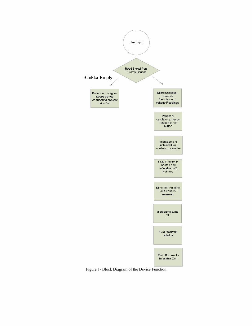
Figure 1- Block Diagram of the Device Function
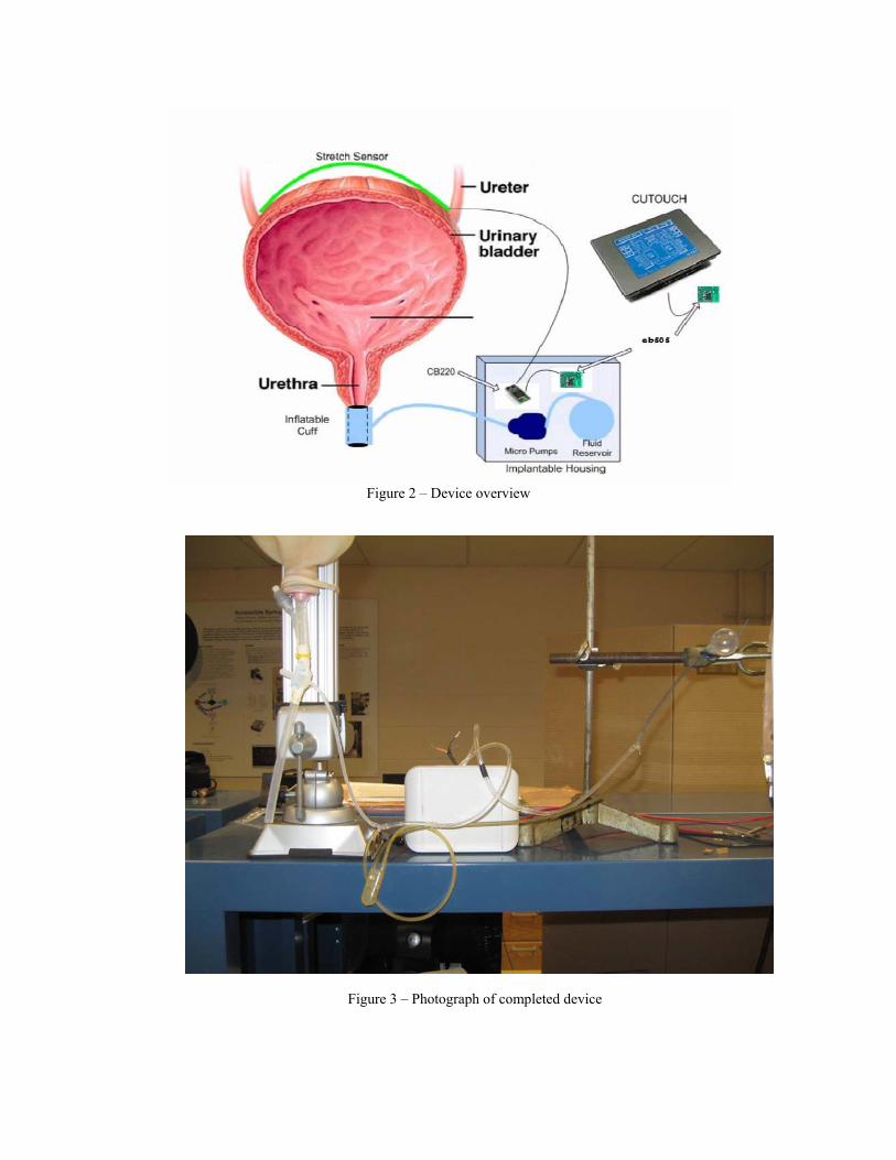
Figure 2 – Device overview
Figure 3 – Photograph of completed device

3.1.1 Remote Control (LCD Screen) A liquid crystal screen (LCD) was used because it consumes very little power, allowing for long battery life. The LCD displays a numerical representation of bladder volume in volume percent, a bar graph illustrating the volume percent of fluid in the bladder and other text outputs for the patient. The LCD screen also has a calendar and time clock which may be helpful for the patient in managing their voiding patterns. This design will use Comfile CuTouch LCD screen (Comfile Technology, CA, USA). This LCD screen is blue with white text and is capable of displaying graphics and characters. The LCD screen is touch screen, which will enable the patient or caregiver to input any information they would like to receive regarding the status of the bladder with minimal pressing force. With the LCD screen the patient or caregiver will be able to visualize what is when the bladder is contracting or relaxing as shown in the figures below.
Figure 4 - Main Menu of the LCD Screen

Figures 5 and 6 below display the numeric and graphical bladder statuses, respectively that the patient can choose between.
Figure 5 – Numeric Bladder Volume Display
Figure 6—Graphical Bladder Volume Display

A main positive feature of the user remote unit, from a patient point of view, is the ease with which the menus and options can me navigated. There are four main menus displayed at the top of the LCD screen, each with their own dropdown menu. Each menu option is described and visually shown below. The “Status” menu drops down into a three option menu. The options are “Numerical”, “Graphical”, and “Audio”. Each option can be selected to provide the user with a different output mode for their bladder status. The “Status” menu is shown below in Figure 7.
Figure 7 – User Remote “Status” Menu
The “Controls” menu allows the user to control the micro pump of the implant and thus control the artificial sphincter cuff and their ability to void urine. There are two active options in the “Controls” menu. The “Relax” option empties the sphincter cuff allowing the user or patient to void their urine. The “Contract” option ensures that the sphincter cuff re-engages after urination is complete to avoid unwanted urine. The “Controls” drop down menu is shown in Figure 8 on the next page.
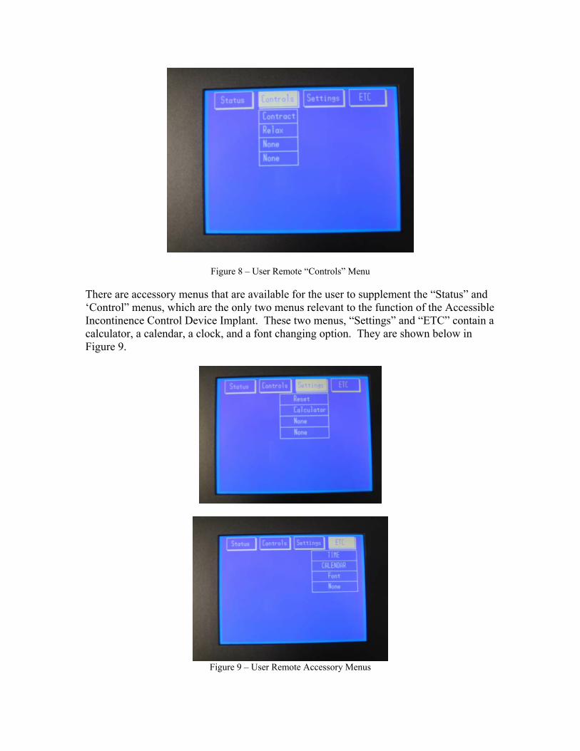
Figure 8 – User Remote “Controls” Menu
There are accessory menus that are available for the user to supplement the “Status” and ‘Control” menus, which are the only two menus relevant to the function of the Accessible Incontinence Control Device Implant. These two menus, “Settings” and “ETC” contain a calculator, a calendar, a clock, and a font changing option. They are shown below in Figure 9.
Figure 9 – User Remote Accessory Menus
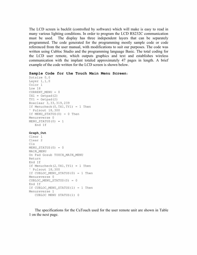
The LCD screen is backlit (controlled by software) which will make is easy to read in many various lighting conditions. In order to program the LCD RS232C communication must be used. The display has three independent layers that can be separately programmed. The code generated for the programming mostly sample code or code referenced from the user manual, with modifications to suit our purposes. The code was written using Cubloc Studio and the programming language Basic. The total coding for the LCD user remote, which outputs graphics and text and establishes wireless communication with the implant totaled approximately 47 pages in length. A brief example of the code written for the LCD screen is shown below.
Sample Code for the Touch Main Menu Screen: Dotsize 0,0 Layer 1,1,0 Color 1 Low 18 CURRENT_MENU = 0 TX1 = Getpad(2) TY1 = Getpad(2) Boxclear 3,33,319,239 If Menucheck(0,TX1,TY1) = 1 Then ' Pulsout 18,300 If MENU_STATUS(0) = 0 Then Menureverse 0 MENU_STATUS(0) = 1
End If
Graph_Out Clear 1 Clear 2 Cls MENU_STATUS(0) = 0 MAIN_MENU On Pad Gosub TOUCH_MAIN_MENU Return End If If Menucheck(2,TX1,TY1) = 1 Then ' Pulsout 18,300 If CUBLOC_MENU_STATUS(0) = 1 Then Menureverse 0 CUBLOC_MENU_STATUS(0) = 0 End If If CUBLOC_MENU_STATUS(1) = 1 Then Menureverse 1
CUBLOC MENU STATUS(1) 0 The specifications for the CuTouch used for the user remote unit are shown in Table
1 on the next page.

CUTOUCH Specifications Microprocessor Dual Core Atmega128
Program Memory (Flash) 80 KB Data Memory (RAM) 24KB(Basic) + 4KB(Ladder)
EEPROM 4KB Program Speed 36,000/sec
General Purpose I/O 82 I/O lines Serial Ports for Communication 2 high-speed serial ports
Analog Inputs 8 channel 10-bit ADCs Analog Outputs 6 channel 16-bit PWMs
External Interrupts 4 channels High Speed Counters 2 channel 16-bit counters
Power 9-24 V DC RTC (Real Time Clock) Yes
Timers 1 user-configurable timer Data Memory Back-up Yes, 1F super-capacitor included Operating Temperature 0-70° C
Package Integrated Touchscreen Panel Size 7.17x5.17x0.98 inches, 4.5x3.4 inch
viewing screen (touch sensitive) Table 1.
A schematic and description of input/output ports is shown below in Figure 10.
Figure 10 - CUTOUCH I/O ports.
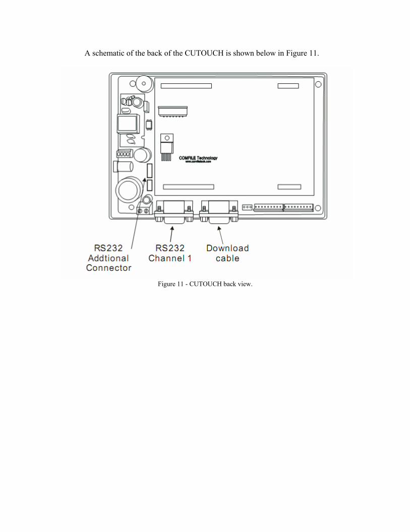
A schematic of the back of the CUTOUCH is shown below in Figure 11.
Figure 11 - CUTOUCH back view.

3.1.2 Microprocessor
A CUBLOC microprocessor (the CB220) was used to run programs to monitor data from the device’s sensors, communicate with LCD display and control the device’s micro pump. The CB220 is shown below in Figure 12.
Figure 12 – CB220 The major tasks of the microprocessor are to:
• Converts resistance from the stretch sensor to voltage using a voltage divider, and then input to volume percent with the output displayed on the LCD
• Controls the artificial sphincter using the micro pump

A schematic of the CB220’s internal structure is shown below in Figure 13.
Figure 13 – CB220 Internal Structure
Programs will be written using BASIC language and the Cubloc Studio software. The CB220 is a programming logic controller, or PLC The main advantage of CUBLOC over other PLCs is that it fills Ladder Logic’s weaknesses with BASIC language. Ladder Logic is good enough to replace sequence diagrams, but to collect data, print graphics, and process complex tasks is too complex for Ladder. Another advantage over other BASIC processors is that CUBLOC is able to separate the amount of work and programming between Ladder Logic and BASIC as necessary. The user is able to debug easier by having two processes work together, instead of trudging through lines of BASIC codes. The CB220 can multitask whereas most PLCs cannot separate their Basic and Ladder commands. This comparison between CB220’s ability to multitask and traditional PLCs is illustrated below in Figure 14.
Figure 14 - CB220 has the ability to multi task with Ladder and Basic.

The CB220 is packaged in a 24 pin DIP package, as shown below in Figure 62. Sixteen of the 24 pins on the CB220 are input/output pins, but far fewer than 16 were needed for our purposes in the Accessible Incontinence Control Device. The pin assignments for the Accessible Incontinence Control Device are also included in Figure 15.
Pin Number Assignment
5 Input from the stretch sensor circuit 10 Output to control the micro pump 15 RX 16 TX 23 Ground 24 Power
Figure 15 - CB220 pin assignments for the Accessible Incontinence Control Device.
The specifications of the CB220 are summarized in Table 2 on the next page.
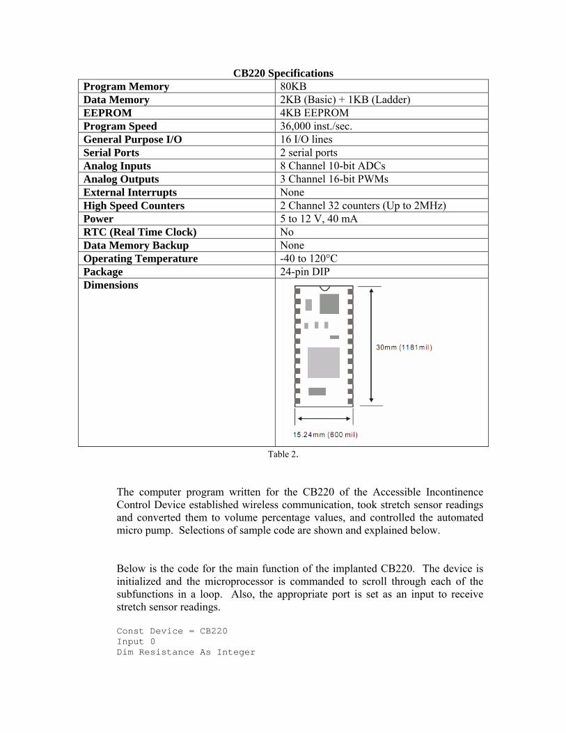
CB220 Specifications Program Memory 80KB Data Memory 2KB (Basic) + 1KB (Ladder) EEPROM 4KB EEPROM Program Speed 36,000 inst./sec. General Purpose I/O 16 I/O lines Serial Ports 2 serial ports Analog Inputs 8 Channel 10-bit ADCs Analog Outputs 3 Channel 16-bit PWMs External Interrupts None High Speed Counters 2 Channel 32 counters (Up to 2MHz) Power 5 to 12 V, 40 mA RTC (Real Time Clock) No Data Memory Backup None Operating Temperature -40 to 120°C Package 24-pin DIP Dimensions
Table 2.
The computer program written for the CB220 of the Accessible Incontinence Control Device established wireless communication, took stretch sensor readings and converted them to volume percentage values, and controlled the automated micro pump. Selections of sample code are shown and explained below. Below is the code for the main function of the implanted CB220. The device is initialized and the microprocessor is commanded to scroll through each of the subfunctions in a loop. Also, the appropriate port is set as an input to receive stretch sensor readings. Const Device = CB220 Input 0 Dim Resistance As Integer

Dim Percent As Byte Dim Relax_Var As String Dim Relax As Integer Dim W As String Dim Z As String Main Sub Main () Delay 1000 Gosub Connect Do Gosub Get_Volt Gosub Get_Relax Gosub Release Loop End Sub
The “Get Volt” subfunction is used to collect 10 readings from the stretch sensor and average these readings. Then the stretch sensor reading is converted to a volume percent.
Get_Volt: Resistance = Tadin(0) If Resistance <525 Then Percent = 0 Putstr 1,"0", Cr Elseif Resistance <540 And Resistance >=525 Then Percent = 25 Putstr 1,"1", Cr Elseif Resistance <552 And Resistance >=540 Then Percent = 50 Putstr 1,"2", Cr Elseif Resistance <=565 And Resistance >=552 Then Percent = 75 Putstr 1,"3", Cr Elseif Resistance >565 Then Percent = 100 Putstr 1,"4", Cr End If Return The “Connect” subfunction establishes a wireless connection with the user remote.
Connect: Opencom 1,9600,3,30, 30 Putstr 1 "con 00:0C:84:00:06:A3" Cr Return The “Get Relax” sunfunction followed by the “Release” subfunction is the function that controls the micro pump. A high signal is sent to turn the pump on, and a low turns the pump off. Get_Relax: Relax_Var = Getstr(1,1)
Relax = Val(Relax_Var) Release: If Relax = 0 Then Delay 100 Elseif Relax = 1 Then High 5 Delay 3500 Low 5 End If Delay 3000 Bclr 1,2 Return
3.1.3 Wireless Transmission
A finished medical implant device would need to use radio frequency, or RF, wireless transmission. The FDA has approved the use of RF transmission on certain wavelengths for medical implant uses. The wavelengths which are approved are able to penetrate body tissue without causing damage. The RF ISM bands that could be used are 325 MHz, 433 <Hz, 868 MHz, and 915 MHz.
For ease of use in this prototype, this prototype will use Bluetooth wireless transmission to communicate between the user remote and the implantable device. The wireless transceiver being used is the Embedded Blue 505 (eb505) serial Bluetooth module. The eb505 will provide direct connection between the remote and the implant. The eb505 module is shown on the next page in Figure 16.

Figure 16 – eb505 module
Wireless technology is being used to prevent the patient from having to wear a device close to their body at all times so that data could be transmitted by wires. It is impractical to use an implant with wires. Running wires from inside the body to outside opens up the possibility of electrical injury to the patient, electrical failure of the device, and infection. Wireless technology is the more efficient and most practical way to convey information about the bladder to an external source. It also makes the device more attractive and marketable than a device that requires wires to transmit data. Bluetooth was chosen for this design because it is easier for electronic devices to communicate with each other using short range radio frequency. Also, Bluetooth utilizes the frequency method of a spread spectrum which uses several radio channels to reduce interference and increase security and reliability of the device. The signal is rapidly switched from channel to channel many times per second in a sender receiver pattern. This pattern provides recovery of any errors that may have been caused by interference from another radio source at a specific frequency. With Bluetooth, the data stored is usually more secure as it is not possible to receive more than a fraction of the data unless the particular programmed pattern between sender and receiver is established. The eb505 Bluetooth uses frequency in the 2.4 GHz radio band and transmits information between sender and receiver at rapid speed with a raw data range of about 1Mbps. The eb505 module supports a maximum sustained bidirectional data speed of 230.4kbps

The wireless transceiver in the user remote will send the user input signal to the transceiver in the implantable device which will trigger the micro pump to turn on and off to allow the patient to release urine when desired. This will result in sphincter contraction and relaxation and thus resulting in the prevention and release of urine from the body. The wireless transceiver in the implant unit will be able to send the volume percentage values to the wireless transceiver in the remote unit, and these values will eventually be displayed on the LCD screen. This transfer of volume percentage data between the implant and the user remote occurs only on demand. The initial paper design for this device called for regular scanning and transmission of bladder status whether the user desired it or not. Although this was supposed to be implemented to alert the user if they have allowed their bladder to get too full, this constant stream of data being sent between the two units places an unrealistic and inefficient demand on the implant’s power source. In an effort to conserve battery life, data will be transmitted wirelessly only at the request of the device user. Figure 17 below diagrams the transfer of information to and from the implanted wireless transceiver.
Figure 17 - Information flow via wireless transceivers.
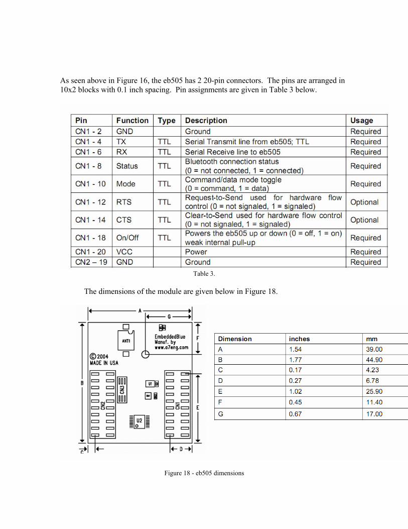
As seen above in Figure 16, the eb505 has 2 20-pin connectors. The pins are arranged in 10x2 blocks with 0.1 inch spacing. Pin assignments are given in Table 3 below.
Table 3.
The dimensions of the module are given below in Figure 18.
Figure 18 - eb505 dimensions

The operating parameters are summarized below in Table 4.
Table 4.
3.1.4 Bladder Status
The bladder status indication portion of the device has been changed from using a pressure transducer to a stretch sensor. This change was made because the stretch sensor was readily available and was more ideal for the status indication. Cost was also a deciding factor between the two status indication methods. Also using the stretch sensor, in replacement of the pressure transducer reduces the amount of power supply that would be needed to operate the device, and would eliminate the need for signal amplification that was necessary to operate the pressure transducer. Although the pressure transducer would give a more precise reading of the bladder status regarding the accuracy of the volume percent of fluid in the bladder, the stretch sensor would be sufficient as the brain itself does not usually recognize the volume of the bladder until it is approximately 50 % full. A urine bag shown below with stretch sensor placed across was used to measure the resistance across the bag as it was filled with fluid for purposes of testing the device and establishing ranges of resistance values to corresponding with each volume percentage. Resistance ranges were measured with the urine bad was 0%,
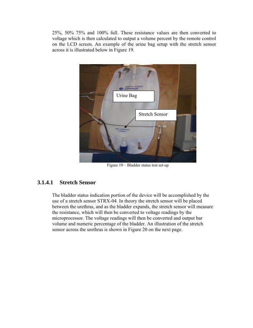
25%, 50% 75% and 100% full. These resistance values are then converted to voltage which is then calculated to output a volume percent by the remote control on the LCD screen. An example of the urine bag setup with the stretch sensor across it is illustrated below in Figure 19.
Figure 19 – Bladder status test set-up
3.1.4.1 Stretch Sensor
The bladder status indication portion of the device will be accomplished by the use of a stretch sensor STRX-04. In theory the stretch sensor will be placed between the urethras, and as the bladder expands, the stretch sensor will measure the resistance, which will then be converted to voltage readings by the microprocessor. The voltage readings will then be converted and output bar volume and numeric percentage of the bladder. An illustration of the stretch sensor across the urethras is shown in Figure 20 on the next page.
Stretch Sensor
Urine Bag
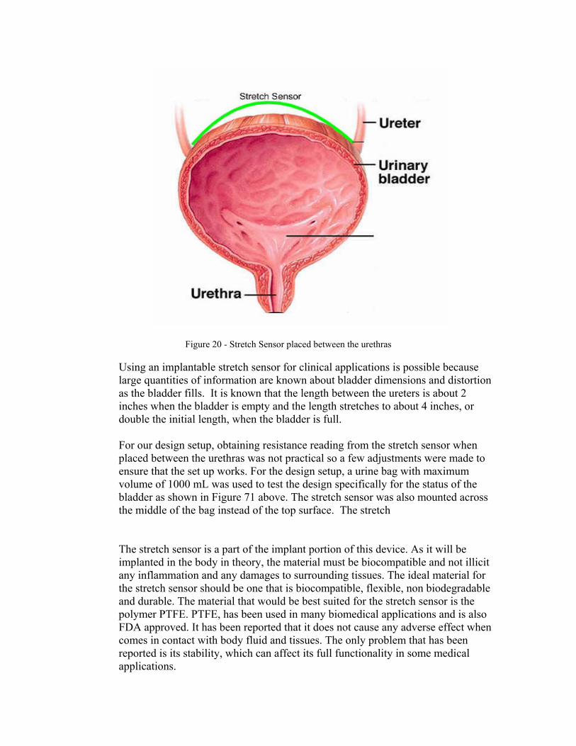
Figure 20 - Stretch Sensor placed between the urethras
Using an implantable stretch sensor for clinical applications is possible because large quantities of information are known about bladder dimensions and distortion as the bladder fills. It is known that the length between the ureters is about 2 inches when the bladder is empty and the length stretches to about 4 inches, or double the initial length, when the bladder is full.
For our design setup, obtaining resistance reading from the stretch sensor when placed between the urethras was not practical so a few adjustments were made to ensure that the set up works. For the design setup, a urine bag with maximum volume of 1000 mL was used to test the design specifically for the status of the bladder as shown in Figure 71 above. The stretch sensor was also mounted across the middle of the bag instead of the top surface. The stretch
The stretch sensor is a part of the implant portion of this device. As it will be implanted in the body in theory, the material must be biocompatible and not illicit any inflammation and any damages to surrounding tissues. The ideal material for the stretch sensor should be one that is biocompatible, flexible, non biodegradable and durable. The material that would be best suited for the stretch sensor is the polymer PTFE. PTFE, has been used in many biomedical applications and is also FDA approved. It has been reported that it does not cause any adverse effect when comes in contact with body fluid and tissues. The only problem that has been reported is its stability, which can affect its full functionality in some medical applications.

The STRX-4 stretch sensor is implanted across the ureters of the patient’s bladder. The STRX-4 is a 4 inch stretch sensor with a resistance of 1000Ω per linear inch, or 4000Ω total, when relaxed. At 50% stretch the resistance approximately doubles. The stretch sensor has a diameter of .060 inches.
3.1.4.2 A/D Circuit
The relationship between the stretch of the space between the ureters as the bladder fills (the length about doubles from an empty bladder to a full bladder) and the changing resistance of the stretch sensor is used to provide the user with the status of their bladder. The resistance across the stretch sensor is passed through an A/D conversion circuit before entering the CB220. This circuit is seen below in Figure 21.
Figure 21 - A/D conversion circuit for stretch sensor readings.
The Zener diode is used to protect against voltage surges. The A/D converter converts the voltage that passes across it to a value between 0 and 1024. It is these A/D values that are used to estimate bladder volume.
3.1.5 Artificial Sphincter
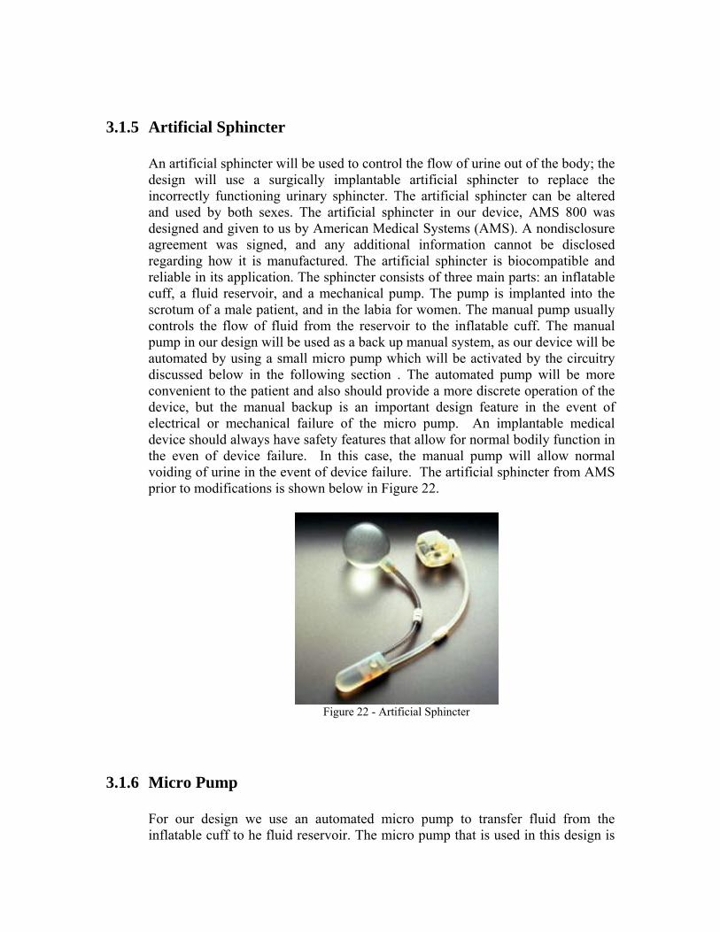
An artificial sphincter will be used to control the flow of urine out of the body; the design will use a surgically implantable artificial sphincter to replace the incorrectly functioning urinary sphincter. The artificial sphincter can be altered and used by both sexes. The artificial sphincter in our device, AMS 800 was designed and given to us by American Medical Systems (AMS). A nondisclosure agreement was signed, and any additional information cannot be disclosed regarding how it is manufactured. The artificial sphincter is biocompatible and reliable in its application. The sphincter consists of three main parts: an inflatable cuff, a fluid reservoir, and a mechanical pump. The pump is implanted into the scrotum of a male patient, and in the labia for women. The manual pump usually controls the flow of fluid from the reservoir to the inflatable cuff. The manual pump in our design will be used as a back up manual system, as our device will be automated by using a small micro pump which will be activated by the circuitry discussed below in the following section . The automated pump will be more convenient to the patient and also should provide a more discrete operation of the device, but the manual backup is an important design feature in the event of electrical or mechanical failure of the micro pump. An implantable medical device should always have safety features that allow for normal bodily function in the even of device failure. In this case, the manual pump will allow normal voiding of urine in the event of device failure. The artificial sphincter from AMS prior to modifications is shown below in Figure 22.
Figure 22 - Artificial Sphincter
3.1.6 Micro Pump
For our design we use an automated micro pump to transfer fluid from the inflatable cuff to he fluid reservoir. The micro pump that is used in this design is

the M100-S Micro Pump from TCS Micro Pumps. The micro pump is the same model as the one chosen from last semester. The pump will be connected to a battery power supply in the device housing and operated through wireless transmission via the user remote control. The micro pump also operates at a temperature range that includes normal body temperature. The pump has an operational temperature range of -20° C to 150° C, which is well within the normal temperatures of the body. The micro pump will be implantable in the abdomen and will be controlled by a wireless remote control. This will provide for an easy to use interface for controlling the flow of urine. By eliminating the manually operated pump from the design, the device will provide a better control system for individuals with disabilities and poor motor skills. Patients also will not have to try and operate a mechanical pump in an undesirable location. This design will be more convenient to the patient and also should provide a more discrete operation of the device.
The pump can be seen in Figure 23 below.
Figure 23 - TMS M100S Micro pump
Figure 24 on the next page shows the micro pump connected to the artificial sphincter cuff in a test set-up.

Figure 24 - Inflatable Cuff and Micro-Pump Setup
Figure 25 below shows a schematic of micro pump control of the artificial sphincter.
Figure 25 - Flow Chart for Micro Pumps

The specifications of the M100-S at 3 volts input, which is the input voltage applied to the pump in this device, are summarized below in Table 5. Micro pump Specifications Input Voltage 3 V Current Draw 0.28 A Power Usage 0.84 W Pressure Head 700 mm Pressure 69 mBar Free Flow Rate 250 ml/min Weight 9 g Operating Temperature -20 - 150°C
Table 5.
The pump body is made of aluminum and the push on connectors for 3/32” tubing are made of stainless steel. An engineering drawing of the pump is shown below in Figure 26.
Figure 26 - Micro Pump

3.1.7 Device Housing The implantable device will contain the thin cell batteries, micro pump, fluid reservoir, the wireless transceiver, and the circuit components for regulating the power supply. The dimensions of the implantable device are 4.724 inches in length, 3.543 inches in width and 1.968 inches in height. The device housing was ordered from okwenclosures.com. The device housing that is currently used to for the implantable portion of our device is not made of biocompatible material and would need to be smaller in theory. The best suited material for the implantable device housing will be made of titanium as it is a biocompatible material which has a relatively low modulus of elasticity and does not include any elements which have been shown or suggested as having short term or long term potential adverse effect from a standpoint or biocompatibility. Titanium is also completely inert to human body fluid. The reasons for avoiding the use of a material like titanium in our actual design are to eliminate the difficulty in fabricating a compartment for the device from this material with limited resources. The housing of the prototype will be created from a simple plastic material that will provide a sturdy support but still be easy to work with to create an adequate enclosure for the components of the design as shown in Figure 79. Titanium will be able to provide a solid structure that would be able to withstand the common impacts that could be received in the abdomen while still providing biocompatible implantable properties. The device housing also needs to have relatively good insulation properties to prevent body fluids from entering the device housing that could possibly damage the circuitry and cause damage to the patient cells and surrounding tissue. In the event that a component would overheat and increase the internal temperature of the device, the housing material should be able to keep most of that generated heat concentrated in the device and not transmit the heat to the surrounding tissue. A model of the enclosure and the components it will contain can be seen in Figure 27 below.

Figure 27 -. Exterior of Implant Device Housing

Figure 28 -. Interior View of the Device Housing

3.1.8 Power Supply The power supply for the implantable portion of the device is constructed of four small cell 3.7 volt Li-ion Polymer batteries (below if Figure 81). The four batteries are connected in parallel to provide optimum battery life for the device. The 3.7 volts is then passed through a circuit that converts the 3.7 volts to 5.0 volts to power the device. The circuit can be seen below in Figure 82. The circuit consists of the LM3224 a Step-up PWM DC/DC Converter from National Semiconductor. Since the device only needs five volts for operation, by connecting four 3.7 volt batteries in parallel we were able to keep the overall size of the device to a minimum and also create an adequate power supply. This same circuit is used again to power the LCD Remote, since it can operate of a 5 volt to 12 volt power supply.
Figure 29 Polymer Li-ion Battery For the actual implantable device a power supply similar to the pacemaker would be used. Since the components don’t need to be operating at all times power consumption can be minimized by turning off the eb505 Bluetooth device when it is not necessary for operation. Also there have been recent advances in powering implantable devices and research for uses of kinetic energy that would recharge implantable batteries as the patient performs simple tasks such as walking. The energy generated by the movement would recharge the implantable batteries and thus supplying the implant with virtually an everlasting power supply.
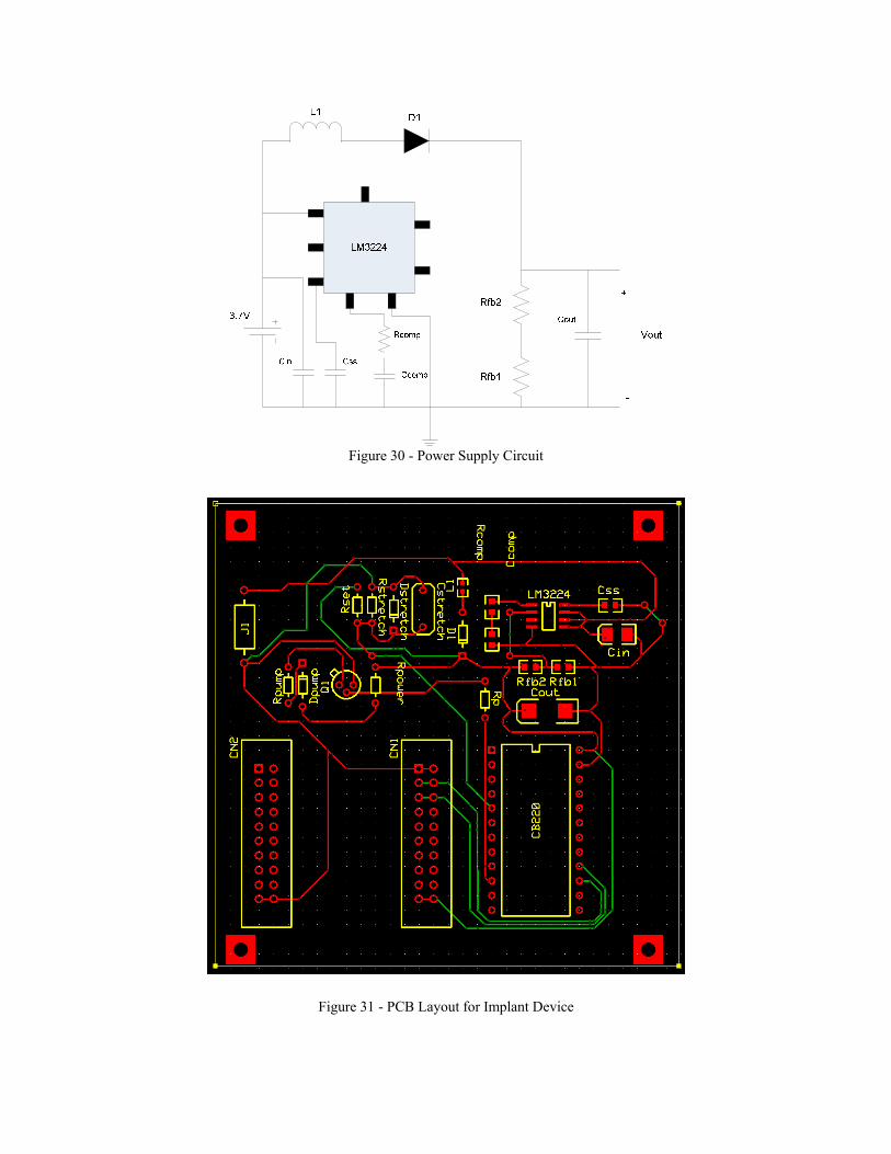
Figure 30 - Power Supply Circuit
Figure 31 - PCB Layout for Implant Device

3.1.9 Optional Device Accessories
3.1.9.1 Interstim® Sacral Nerve Stimulator
The artificial sphincter of the Accessible Incontinence Control Device is designed to aid patients with urinary incontinence that leads to undesired voiding of urine. An artificial sphincter can treat patients with stress, urge, mixed, or functional incontinence. Overflow incontinence, which results from urinary retention, or the body’s inability to contract the bladder, cannot be treated by an artificial sphincter. About 10-15% of all urinary incontinence patients experience overflow incontinence. The condition is more common in men, and causes include enlarged prostate, diabetes mellitus, spinal cord injury, damaged sacral nerve, and certain medications. Overflow incontinence can be treated with Interstim® therapy. Patients who experience overflow incontinence should talk to their physician about replacing the artificial sphincter component of the Accessible Incontinence Control Device with the Interstim® Sacral Nerve Stimulator. The device will maintain its ability to control urination and provide the status of the bladder.
Figure 32 - Placement of the Interstim® therapy system.
3.1.9.2 Smart Phone as User Remote Unit Having the user remote computer program uploaded to a Smart phone, or other similar device, is a good option for Accessible Incontinence Control Device users who are active and spend a lot of time outside their home. This option provides the user with a portable user remote that can be easily used in public places without having to find a bathroom with a power socket in close proximity to the toilet. In addition, it is a smaller and more lightweight option than the included user remote, as well as more discrete.

2. Background and Client Needs
Urinary incontinence is a major problem millions of men and women. Between 10 and 30% of adults are afflicted with urinary incontinence, or about 13 million Americans. Urinary incontinence occurs more commonly with an increase in age. Patients who suffer from urinary incontinence sometimes develop it as a result of other diseases such as pathology, spinal cord injuries, brain trauma and also as a side effect to medications. Urinary incontinence occurs when patients have a dysfunctional bladder, sacral nerve, or urinary sphincter. A dysfunctional bladder may cause overflow of urine or partial release of urine from the bladder. An overflow of urine from the bladder occurs when an inactive bladder muscle doesn’t fully contract occurring in a less active bladder resulting in swelling or stretching of the internal sphincter. When the urinary sphincter is dysfunction it causes unwanted leakages leading to embarrassment and discomfort of the patients. A dysfunctional sacral nerve results in urinary retention which in turn will eventually lead to urine overflow. The overflow of urine causes skin irritation and external infection. The partial release or no release of urine from the bladder often results in urinary tract infection and internal infections causing the patients to be in a lot of pain. In addition to clinical problems associated with urinary incontinence, patients suffering from this condition face public embarrassment, greatly altered lifestyle, and general decreased quality of life. For this project a fictional list of potential clients was provided. There were three clients who could benefit from the use of an accessible incontinence control device. Keisha is an 84 year old female stroke victim with hemiplegia on the right side of her body. This means a device would have to be created that she could control using only one hand. In addition to incontinence she suffers from memory and hearing losses, requiring a simple to use device with visual output. Jerry is an 82 year old male Parkinson’s patient. Besides incontinence his symptoms include tremor, rigidity, decreased range of motion, and some dementia. Jamie is a female 44 year old who suffered a T11 spinal cord injury. She is confined to a manual wheelchair and she wants better urinary control when she is playing basketball.

3. Budget
The maximum budget we were allocated to complete this project was $2000. This funding was provided by the RERC on Accessible Medical Instrumentation (RERC-AMI) student design competition. As is shown in Table 6 below, of our total expenditures, our team spent $1551.66. There was $448.34 remaining that would have been available for our use had we needed it.
Total Budget Expenses
COMPONENT MODEL/
PART NUMBER QUANTITY ITEM COSTSHIPPING
COST TOTAL COSTMicro Pump M100-S 2 NA NA $196.49 Tygon Tubin (3/32") 57361 10 $0.80 $5.80 $13.80 Standard Foley Catheter Size 26FR - 30 CC 1 $4.95 $8.95 $13.90 Thin Cell Battery PL-052025 4 $5.95 $7.83 $31.63 Smart Charger CH-UNCE001A 1 $9.95 $9.95 CuTouch U06003 1 $402.00 $10.00 $412.00 CB220 U01002 1 $34.00 $34.00 ACODE-300 B01001 2 $59.00 $118.00 ACODE300 I/F B02001 1 $19.00 $19.00 ACODE PROTO U02003 1 $5.00 $5.00 Adapter E01065 1 $22.00 $22.00 Digestion Kit NA 2 $45.44 $90.88 Stretch Sensor 4 inch strx-4 1 $10.95 $12.50 $23.45 Stretch Sensor 8 & 10 inch strx-8 and strx-10 2 $31.90 $12.50 $44.40 Latex Tubing RS312RA10 1 $9.50 $9.31 $18.81 Thin Cell Batterys PL-053048H 4 $9.95 $8.29 $48.09 Power Supply Parts NA $32.48 $32.48 BlueTooth eb505 2 $69.00 $22.62 $160.62 Urine Collection Bag NA 2 $12.85 Check Valve cvp-02-01 2 $4.50 $13.49 $17.99 Reduction Coupler 64267 2 $0.27 $9.88 $10.69 PCB Board NA 2 $156.39 $156.39 Misc. Parts NA $39.86 $39.86
Total: $1,551.66
Table 6.

Since we had several design changes during the course of the semester we did not use all of the parts that we ordered. In addition, some of our budget went to developing a test set-up that could be used to evaluate the implant without being able to implant it. Table 7 below summarizes the cost of parts that were directly used to make the device. The total cost to build the device was $1129.40.
Cost to Build Implantable Device
Table 7.
COMPONENT MODEL/PART
NUMBER QUANTITYITEM COST
SHIPPING COSTS
TOTAL COST
Micro Pump M100-S 2 NA NA $196.49 Tygon Tubin (3/32") 57361 10 $0.80 $5.80 $13.80 Thin Cell Battery PL-052025 4 $5.95 $7.83 $31.63 CuTouch U06003 1 $402.00 $10.00 $412.00 CB220 U01002 1 $34.00 $34.00 Stretch Sensor 4 inch strx-4 1 $10.95 $12.50 $23.45 Power Supply Parts NA $32.48 $32.48 BlueTooth eb505 2 $69.00 $22.62 $160.62 Check Valve cvp-02-01 2 $4.50 $13.49 $17.99 Reduction Coupler 64267 2 $0.27 $9.88 $10.69 PCB Board NA 2 $156.39 $156.39 Misc. Parts NA $39.86 $39.86
Total: $1,129.40