Embed Size (px)
Citation preview

Code 33447 RESCUE 230 BIPHASIC DEFIBRILLATOR
GIMA S.p.A. – Via Monza, 102 – 20060 Gessate (MI) – Italia ITALIA: Tel. 02 953854.1 – Fax. 02 95381167
e-mail: [email protected] – www.gimaitaly.comEXPORT: Tel. +39 02 953854209/221/225 – Fax. +39 02 95380056
e-mail: [email protected] – www.gimaitaly.com
USER MANUAL VER 1.1 – March 2006 1

RESCUE 230 ver External Biphasic Defibrillator With ECG monitoring User manual Safety instructions
General
- Assure yourself prior and after the use of the RESCUE 230 that the unit is in safe and usable condition (cables integrity, battery status).
- RESCUE 230 is not intended for use in areas of highly inflammable anesthetics or
other inflammable substances, especially in oxigenous areas. - RESCUE 230 does not have to be put or used nearby a nuclear spin tomography
plant, which is turned on.
Defibrillator
- Defibrillation must be performed only by responsible trained doctors. - Be sure that both surfaces of the shock paddles are completely moistened with
gel. - The shock paddles must be held at distance from other electrodes and any metal
parts in contact with the patient. - The patient must not be touched during defibrillation. - Be sure that the parts of the patient body, such as the head or limbs are not in
touch with metal parts, bed frames or stretchers, in order to prevent accidentally creating current path for the defibrillation impulse.
- During defibrillation with connected ECG cable ensure that all binding clips are
connected with the patient. - When defibrillating children do not exceed 50J. - The shock paddles including handles should always be cleaned thoroughly after
use.
USER MANUAL VER 1.1 – March 2006 2

USER MANUAL VER 1.1 – March 2006 3
INTRODUCTION Thank you for choosing the RESCUE 230. Please read this Operator’s Manual carefully and thoroughly before using the RESCUE 230. This Manual contains instructions on how to operate and maintain the RESCUE 230.
It is very important that you fully understand all the necessary instructions discussed in this manual so as to act quickly in an emergency.
Rescue 230 complies with international standards (93/42/EEC). This ensures high quality and reliability. In this regard:
Only persons authorized by GIMA S.p.A. should do all servicing of the device. There are no user serviceable parts in this device. You should operate this device in accordance with the instructions specified in this manual.
This device has to be operated by personnel who have undergone training in Advanced Cardiac Life Support. In this mode, the operator must know how to interpret ECGs.
To ensure safety and reliability, use only parts and accessories recommended by GIMA S.p.A.
If you intend to use this device in conjunction with other devices not specified in this manual, please notify the manufacturer.

USER MANUAL VER 1.1 – March 2006 4
WARRANTY
This device is designed and manufactured according to European standards ( 93/42/EEC). Every defibrillator that goes out of the assembly line passes through a full reliability tests. In case of problems, our maintenance and exchange policies are in accordance with the relevant consumer protection laws and regulations in the particular country where the device is sold.
The warranty period of this device is within one year after the date of purchase.
When the device malfunctions during the warranty period (RESCUE 230 subjected to operating conditions within the specified limits), it will be repaired free of charge at our service centers.
When you submit the device for maintenance, please specify the details as listed below : The name of model, product serial number, date of purchase, name of sales representative, information of customer and a brief description of the problems.
Name of Product Manual Biphasic Defibrillator
Model RESCUE 230 Serial No.
Date of Purchase Sales Representative
Address
Name Customer Information
Contact No.
Brief Description of Problems

USER MANUAL VER 1.1 – March 2006 5
Service Only GIMA S.p.A. or its authorized representatives should service the device. If unauthorized personnel service the device during the warranty period, the warranty will become null and void. GIMA S.p.A. or its authorized representatives are obliged to service the device free of charge during the warranty period. When the device is not functioning properly, it has to be submitted for maintenance immediately. When any abnormalities are found in the device or when a danger to bodily harm exists, the device has to be repaired fast and adequately by authorized personnel. When the need for maintenance arises:
Please contact GIMA S.p.A. or its authorized representatives immediately. Prepare a summary
of the problems. Also include the name of model, product serial number, date of purchase, name of sales representative, Customer. information
There are no user-serviceable parts in the RESCUE 230. The user should not attempt any repair beyond what we recommend in the maintenance section of this manual.

How to Use This Manual Contents of This Manual
This Operator’s Manual contains all the information a user needs to operate the RESCUE 230
properly. In case you have any problems regarding the operation of the device, please don’t hesitate to
contact the manufacturer. Safety Messages
The following safety messages are used to emphasize the safety practices that must be observed and followed during the operation of the RESCUE 230. The operator must follow the instructions in all the Danger, Warning, Caution, and Notice messages found throughout this Operator’s Manual
In the event that the device is damaged due to misuse or negligence by a user, the manufacturer or the authorized representatives shall not be responsible for the damage or loss to the product.
Immediate hazards that will result in personal injury or death.
Conditions, hazards, or unsafe practices that can result in serious personal injury or death.
Conditions, hazards, or unsafe practices that can result in minor personal injury, damage to the RESCUE 230, or loss of data stored in the device.
Used to denote items that are important during installation, operation, or maintenance of the device.
USER MANUAL VER 1.1 – March 2006 6
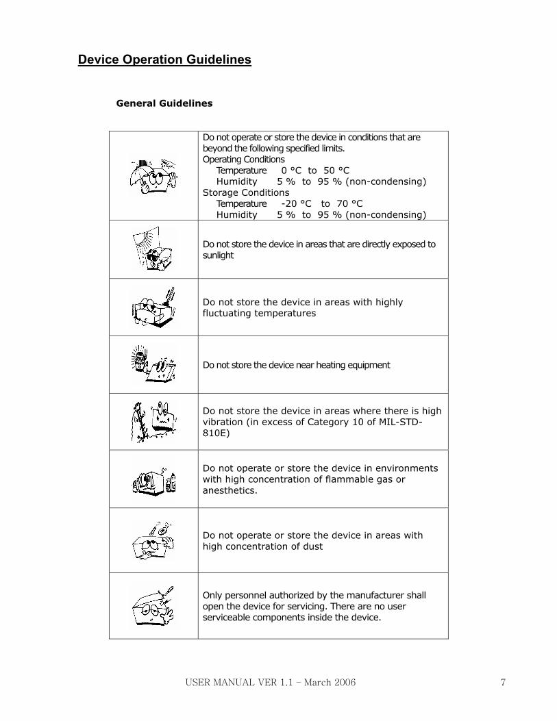
Device Operation Guidelines
General Guidelines
Do not operate or store the device in conditions that are beyond the following specified limits. Operating Conditions
Temperature 0 °C to 50 °C Humidity 5 % to 95 % (non-condensing)
Storage Conditions Temperature -20 °C to 70 °C Humidity 5 % to 95 % (non-condensing)
Do not store the device in areas that are directly exposed to sunlight
Do not store the device in areas with highly fluctuating temperatures
Do not store the device near heating equipment
Do not store the device in areas where there is high vibration (in excess of Category 10 of MIL-STD-810E)
Do not operate or store the device in environments with high concentration of flammable gas or anesthetics.
Do not operate or store the device in areas with high concentration of dust
Only personnel authorized by the manufacturer shall open the device for servicing. There are no user serviceable components inside the device.
USER MANUAL VER 1.1 – March 2006 7

Storage and Operating Environment Guidelines
Avoid damp locations. Do not operate and store the device beyond the specified limits. Do not
operate the device with wet hands. Do not expose the device to direct sunlight during storage. Do not store the device in areas with highly fluctuating temperatures. Do not store the device close to heating equipment and appliances. Do not store the device near sources of vibration. Do not store and operate the device in locations that are exposed to chemicals, explosive gas
and solvents. Keep the device away from dusty environments. There are no user serviceable parts inside the RESCUE 230. Only authorized service personnel
should open the device for repairs. During recharging, when the device is connected and disconnected from the mains power
connector, hold the plug and not the electrical cord.
Operating environmental condition limits: Temperature: 0 °C to 50 °C Relative Humidity: 5 % to 95 % (non-condensing)
Storage environmental condition limits:
Temperature: -20 °C to 70 °C Relative Humidity: 5 % to 95 % (non-condensing)
Do not use the RESCUE 230 if it has been submerged in water. Call immediately for service assistance.
Electrical Safety Guidelines
Use the only the original power supply during recharging. See the section Chapter on Power Supplies for more details.
During recharging, do not place the device where the environmental conditions exceed the storage conditions specified in the Storage and Operating Environment Guidelines
During operation, the device should be placed away from sources of electromagnetic interference such as motors, generators, X-Ray equipment, radio transmitters, cellular mobile telephones and others, as these might interfere with the signals being acquired.
The RESCUE 230 is classified as follows: - It is a Class II, BF equipment in terms of electrical shock prevention (EN 60601-1). It is not proper to operate this device around combustible anesthetic or solvents. - For the ECG patient cable is a Class II, CF (EN60601-1). - The Electromagnetic emission level is Class B according to EN 60601-1 (Safety of Electric Medical Equipment), and the noise redemption is B level according to the EN 60601-1-2
USER MANUAL VER 1.1 – March 2006 8

Cleaning and Maintenance After each use, clean the RESCUE 230 using a soft, damp cloth moistened with any of the following solvents: Soap and water 70% solution isopropyl alcohol Chlorine bleach and water mixture (30 ml bleach/liter of water) Ammonia-based cleaners Hydrogen peroxide
Do not immerse any part of the RESCUE 230 in fluids. Do not let any fluid enter the case of the device. Do not spill liquids on the case of the device. Do not use strong, acetone-based cleaners in cleaning the device. Do not use abrasive materials in cleaning the unit, especially on
the LCD display. Do not sterilize the RESCUE 230.
Although there are no user serviceable parts inside the RESCUE 230, the operator can do maintenance checks that will help ensure that the device stays in mint condition.
Check the case of the device for any apparent damage. Check the ports (defibrillator lead port, adapter power port) to see that they are tightly in
place. Check the accessories, especially the defibrillation pads, to see that they are in good condition
and for the disposable pads, that they have not yet reached their expiration dates. Check the battery status and if it under 75%, please connect the AC charger.
USER MANUAL VER 1.1 – March 2006 9

Product Description The RESCUE 230 is a manual external defibrillator and ECG Monitoring. It is a battery powered, lightweight and portable device designed to deliver defibrillation shocks during rescue operations. The user has to do the analysis of the ECG of the patient and set the energy of the shock to be delivered. The choices are 10, 20, 30, 50, 100, 150, 200 and 230 (all in Joules). The energy value can be fine tuned from 3 to 10J in steps of 1J and from 10 to 230J in steps of 5J. Synchronized cardioversion can also be done. During synchronized cardioversion, the defibrillating shock is delivered within 40 milliseconds of the occurrence of a QRS peak. The RESCUE 230 may also be used to do ECG monitoring. ECG monitoring only is done by connecting the custom designed, 4 leads ECG monitoring cable assembly from GIMA S.p.A. In this case RESCUE 230 will display/print 3+3 traces ( I,II,III – aVR,aVL,aVF). The RESCUE 230 may be equipped with disposable defibrillation pads. Through these pads, the electrical signal from the patient’s heart is acquired. The defibrillation shock is delivered also through the same defibrillation pads
The RESCUE 230 is NOT intended for pediatric use. It may be used in children over the age of 8 years (weighing 25kg or above). In any case, the decision to defibrillate is of the operating doctor.
Do not remove or change the internal battery pack. If it is necessary to have it changed, contact the manufacturer or its authorized representatives.
USER MANUAL VER 1.1 – March 2006 10

USER MANUAL VER 1.1 – March 2006 11
Intended Purposes
Indications Asynchronous defibrillation – the shock delivery is not synchronized with the QRS peak In asynchronous defibrillation, the RESCUE 230 is indicated for use on patients with the following symptoms
a) Unconsciousness b) Absence of normal breathing and c) Lack of detectable pulse. Synchronous defibrillation – the shock delivery is synchronized with the QRS peak of the patient’s ECG. In synchronous defibrillation, the RESCUE 230 is indicated for use on patients with ECGs that show the presence of Atrial Fibrillation:
Contraindications The RESCUE 230 should not be used on patients that: a) Are conscious b) Are breathing normally c) Have detectable pulse. Intended Users The RESCUE 230 is intended for use by health care professionals and emergency rescue personnel who have been trained in advanced cardiac life support. The user must know how to interpret ECGs.
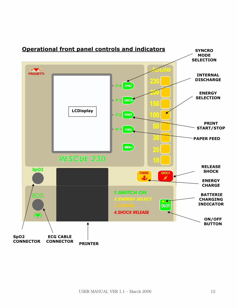
Operational front panel controls and indicators
ON/OFF
BUTTON
ENERGY SELECTION
ENERGY CHARGE
INTERNAL DISCHARGE
SYNCRO MODE
SELECTION
BATTERIE CHARGING INDICATOR
PRINTER
ECG CABLE CONNECTOR
RELEASE SHOCK
PRINT START/STOP
SpO2 CONNECTOR
PAPER FEED
LCDisplay
USER MANUAL VER 1.1 – March 2006 12

FRONT PANEL CONTROL FUNCTIONS KEYS
Key ON/OFF
Power On-off push button of RESCUE 230 At switch on, if the padles are disconnected, the battery status and clock set-up screen will appear . To set-up the clock use F1-F3 keys else to start ECG monitoring press F1 key. To shut-off the device press the ON/OFF key only once.
Key SHOCK
When the red light inside this key is on it means that RESCUE230 is ready to defibrillate. Pressing this key will release the defibrillation shock. (This key is active only when disposable pads are used). To release the shock with the standard pads press both pushbuttons on the pads handles.
Key CHARGE
This key will start the energy charging to the selected level. It is active only with the disposable pads. To start the charging with the standard pads press both
pushbuttons on the pads handles.
Key MENU
Controls the device set-up functions. When pressed, on the display will appear the specific functions for the F1-F4 keys.
Key SYNC
Used for the sync mode (defibrillation will be done in sync with the R-wave of the ECG complex). The sync mode is displayed on the screen.
Key DISCH
Pressing this key will discharge the energy internally. (If no discharge is actuated, after 30 sec the RESCUE 230 will discharge internally the energy).
ENERGY selection
keys
Used to select the energy level desired. The corresponding light will switch on and the energy value will be displayed on the screen.(set value).
Key PRINT
Enables to obtain a hardcopy of the ECG traces and the device set-up values.
Key FEED
Paper feed key.
USER MANUAL VER 1.1 – March 2006 13

USER MANUAL VER 1.1 – March 2006 14
Keys F1-F4 secondary functions
Pressing the MENUE key on the screen the secondary functions of F1-F4 will be displayed. The functions are described on the following table:
BASIC FUNCTION MENU 1 MENU 2
F4 DSCH –internal discharge Change the ECG traces displayed/printed: I,II,III or aVR,aVL,aVF
Enable/disable the NOTCH filter (line noise)
F3 SYNC – set sync mode Set the scan velocity: 5mm/s,12.5mm/s or 25mm/s
Enable/disable the LP filter (muscular tremors)
F2 PRINT – start/stop printing Set the ECG trace gain: 5mm/mV,10mm/mV or 20mm/mV
F1 FEED – paper feed Enable/disable the HP filter (base line stability)
SAVE the device set-up parameters.
Light indicators
BATTERY Charging Light (on the ON/OFF
key)
Indicates that the AC power supply is connected and the batteries are charging. When the charge is finished this light will switch off. When RESCUE 230 is switched on, the light may be on even if the batteries are fully charged (the device is in backup mode, using the batteries and the AC supply)
ENERGY Selection Light (on the energy selection keys)
The light indicates the energy level selected .
DEFIBRILLATION ENERGY READY
(on the shock Key)
Indicates that the energy selected was charged and the device is ready for defibrillation.

USER MANUAL VER 1.1 – March 2006 15
Display Messages guide
CHECK PADS The defibrillation pads are disconnected.
IMPEDANCE Indicates the impedance out of range (min 20 ohm, max 200 ohm). Verify the pads contact with the patient chest and add more conductive gel.
ARMING RESCUE 230 is charging the capacitor to the energy level selected.
READY
Indicates that the capacitor is charged and the device is ready for defibrillation. In Sync mode the shock will be released only when a valid ECG wave R peak is detected. In this mode make sure a valid ECG trace is available on the display.
BAT OK/LOW Indicates the battery status. If LOW then please connect the AC power supply.
Display organization When the 4 leads ECG patient cable is disconnected, the display will show only one ECG trace (II) input from the defibrillation pads. Connecting the 4 leads ECG patient cable the display will show 3+3 ECG traces: I,II,III or aVR,aVL,aVF based on the user selection (see menu functions). Please make sure to connect all ECG patient cable terminals to the patient limbs before proceeding with the defibrillation.
Using the SpO2 sensor option, the display will show only 2 ECG traces (patient cable connected) and the SpO2 wave. The So2 and the heart rate will be displayed on the bottom left side of the display. The heart rate on the top of the screen is related only to the ECG signals. The display also indicates the selected energy level, the filters status, the gain and velocity of the ECG wave as well as the battery status and the clock (date and time).

DEFIBRILLATION PADS CONNECTORS
AC POWER SUPPLY CONNECTOR
USER MANUAL VER 1.1 – March 2006 16

Input Connectors
Defibrillation Pads input (left side down)
Used for the defibrillation pads. For the disposable pads please order also the adapting cable.
SpO2 input (front panel)
Used for the SpO2 sensor (optional). The RESCUE230 will automatically recognize the sensor and will modify accordingly the display.
ECG patient cable input (front panel)
Input for the ECG 4 leads patient cable. The RESCUE230 will automatically recognize the cable and will modify the accordingly the display.
Battery charger AC power supply (right side down)
Battery charger and AC power supply input. USE ONLY THE ORIGINAL AC POWER SUPPLY.
Device Preparation Unpacking 1) Carefully inspect the packing container and the device for any damage that might have been
sustained during shipping. 2) Check the shipping list to ensure that the unit comes with the complete accessories.
It is important to have all the necessary accessories all the time. Make sure that you have the complete accessories during unpacking.
USER MANUAL VER 1.1 – March 2006 17

Defibrillation pads connectors plug-in Push the connector (STERNUM-APEX) up to the end and turn it right until it locks. To unplug the connectors, pull the connector lever and turn it left up to the stop and then pull it out.
PADS CONNECTUORS INSERTION
Patient Preparation
Evaluate the condition of the patient. The patient must exhibit the symptoms for which the defibrillation is indicated. These symptoms are:
Unconsciousness Absence of normal breathing and Lack of detectable pulse.
If the patient is exhibiting the said symptoms, do the following:
- Remove clothing from the patient’s chest. Wipe moisture and clip or shave excessive chest hair. - If using the standards pads, make sure to use on each one enough conductive gel. - If using disposable pads, peel off their protective sheets. Attach the pads to the patient. The sticky side must be in contact with the patient’s skin. Place the pads in accordance with the graphic guide at the back of the pads. The placement is also shown in the figure below
USER MANUAL VER 1.1 – March 2006 18

USER MANUAL VER 1.1 – March 2006 19
APEX
STERNUM
Defibrillation procedure 1. Switch on the device using the ON/OFF push button. By default the energy is set to 150 J. The ECG trace and the heart rate will be displayed . 2. Select the energy level required. 3. If you are using the standard pads, press both push buttons on the handles to start charging to the selected energy. If you are using disposable pads press the CHARGE push button to start charging. The ARMING message will be displayed and the charging sound will start. When the charge ends the READY message will be displayed and on the SHOCK key the red light will go on. This means that the RESCUE 230 is ready for defibrillation. 4. To release the defibrillation shock, press both push buttons on the standard pads or press the SHOCK key if using disposable pads. The RESCUE 230 will discharge internally after a 30 sec wait time. If the defibrillation is not required, press the DSCH (F4) key to discharge internally.
If the IMPEDANCE message is displayed then add more gel on the pads or press harder the pads on the patient chest. The RESCUE 230 will not release the shock if the impedance is out of range. In the sync mode the shock will not be released unless the ECG wave is valid.
Please make sure nobody touches the patient during the defibrillation.
Make sure that all electronic devices which may disturb the ECG trace must be placed at a safe distance from RESCUE 230 before defibrillation.
The RESCUE 230 is not intended for pediatric use. It should not be used on patients with an age inferior of 8 years or with a body weight less than 25 Kg.

PRINTING AND PAPER CHANGE To start the printing press the PRINT (F2) key. The hardcopy will start with the set-up parameters and with the ECG trace. The hardcopy will keep the display set-up (velocity, gain and number of traces ) To stop the printing please press again the PRINT (F2) key. When the paper is finished the ‘PAPER’ message will be displayed. To replace the paper, open the printer cover (see the image below), insert a new paper roll with the thermosensible side up and then close the cover. Push the FEED key until the paper comes out straight.
Opening the printer cover
USER MANUAL VER 1.1 – March 2006 20

Battery charge When the ‘BAT LOW’ message is displayed please connect the AC charger. The battery charge light should go on. When the batteries are fully charged the light will go off. To see the battery charge status, switch on the RESCUE 230 with at least one pad disconnected. The battery charge status will be displayed. If it shows less than 75% than please connect the AC charger.
Please use only the original charger. Do not leave the AC charger connected more than 5 hours. If after this time the charging light does not go off, please contact the service center.
Date/Time setup To set-up the real time clock, switch on the RESCUE 230 with at least one pad disconnected. On the screen will be displayed the battery status, the date and time. The F4 key enables the clock set-up. With the F3 key choose the value to change and with the F2 key you can modify the value. To exit the clock set-up press again the F4 key. Pressing the F1 key the ECG monitoring will start.
USER MANUAL VER 1.1 – March 2006 21

USER MANUAL VER 1.1 – March 2006
TECHNICAL DATA ECG Monitoring • Patient connection : Defibrillation pads or 4 leads ECG patient cable • Bandwith: 0.5 to 140 Hz (-3 dB) with filters off • ECG trace parameters: Velocity : 5,12.5,25mm/sec Gain: 5,10,20 mm/mV Traces: 3+3 (I,II,III – aVR,aVF,aVL) with 4 leads patient cable • Heart rate: Digital readout on the display from 20 a 300 bpm (± 2%)
Defibrillator
• Operation mode: Manuale • Wave type: Biphasic (Truncated exponential) with impedance compensation • Energy: Levels: 10,20, 30, 50,100, 150, 200, 230 J Fine levels: from 3 J to 10J in steps of 1 J and from 10 J to 230J steps of 5 J • Defibrillatable impedance : da 20ohm a 200ohm • Energy charging time: Less than 7 sec (with batteries fully charged) • Syncro Mode or normal mode
• Defibrillation pads: Standard or disposable Display/ Printer • High resolution LCDisplay • LCD Dimensions: 5.7 inches diagonale, 320X240 pixels • Thermal printer 200dpi on 58mm paper Device Dimensions • Dimensions: 340 mm X 260 mm X 130 mm (L X W X H) • Weight 5.5 kg including pads and AC charger AC charger power supply • Input: 100 ~ 240V AC 50/60Hz max. 1A • Output: 12V DC, 2.5A Battery pack • 12V battery Ni-Cd (internal rechargeable) • charging time 3 to 4 hours • capacity : 100 shocks (battery fully charged)

INDEX
Safety Instructions Page 2
Introduction Page 3
Warranty Page 4
Service Page 5
How to use this manual Page 6
Device operation guidelines Page 7
Storage and operating environment guidelines Page 8
Cleaning and maintenance Page 9
Product description Page 10
Intended purposes Page 11
Operational front panel controls and indicators Page 12
Front panel control functions keys Page 13
Keys F1-F4 secondary functions Page 14
Light indicators Page 14
Display messages guide Page 15
Display organization Page 15
Input connectors photo Page 16
Input connectors Page 17
Device preparation Page 17
Patient preparation Page 18
Defibrillation procedure Page 19
Printing and paper change Page 20
Battery charge Page 21
Date/time set-up Page 21
Scope of delivery Page 22
Technical data Page 22
Biphasic waveform Page 24
Elctromagnetics emissions Page 25
Electromagnetic Immunity Page 26
Recommended separation distances Page 29
USER MANUAL VER 1.1 – March 2006

Biphasic waveforms The following waveforms are the RESCUE 230 output for a maximum of 230 Joule:
USER MANUAL VER 1.1 – March 2006

USER MANUAL VER 1.1 – March 2006
TABEL 201
Guida e dichiarazione del costruttore – emissioni elettromagnetiche
Guidance and manufacturer’s declaration – electromagnetic emissions L’apparecchio Rescue 230 è previsto per funzionare nell’ambiente elettromagnetico sotto
specificato. Il cliente o l’utilizzatore dell’apparecchio Rescue 230 dovrebbe assicurarsi che esso
venga usato in tale ambiente. The equipment Rescue 230 is intended for use n the electromagnetic environment specified below. The customer or the user of Rescue 230 should assure that it is used in such an environment.
i
Prova di emissione Emissions test
Conformità Compliance
Ambiente elettromagnetico – guida Electromagnetic environment - guidance
Emissioni RF RF emissions CISPR 11
Gruppo 1 Group 1
L’apparecchio Rescue 230 utilizza energia RF
solo per il suo funzionamento interno. Perciò le
sue emissioni RF sono molto basse e
verosimilmente non causano nessuna
interferenza negli apparecchi elettronici vicini. The equipment Rescue 230 uses RF energy only for its internal function Therefore, its RF emissions are very low and are not likely to cause any interference in nearby electronic equipment.
.
Emissioni RF RF emissions CISPR 11
Classe B Class B
Emissioni armoniche Harmonic emissions IEC 61000-3-2
Classe A
Class A
Emissioni di fluttuazioni
di tensione/flicker Voltage fluctuations/ flicker emissions IEC 61000-3-3
Conforme
Complies
L’apparecchio Rescue 230 è adatto per l’uso in
tutti i locali compresi quelli domestici e quelli
collegati direttamente ad un’alimentazione di
rete pubblica a bassa tensione che alimenta
edifici usati per scopi domestici. The equipment Rescue 230 is suitable for use in all establishments, including domestic establishments and those directly connected to the public low-voltage power supply network that supplies buildings used for domestic purposes.

USER MANUAL VER 1.1 – March 2006
TABEL 202
Guida e dichiarazione del costruttore – immunità elettromagnetica Guidance and manufacturer’s declaration – electromagnetic immunity L’apparecchio Rescue 230 è previsto per funzionare nell’ambiente elettromagnetico sotto
specificato. Il cliente o l’utilizzatore dell’apparecchio Rescue 230 deve garantire che esso venga
usato in tale ambiente. The equipment Rescue 230 is intended for use in the electromagnetic environment specified below. The customer or the user of Rescue 230 should assure that it is used in such an environment.
Prova di immunità Immunity test
Livello di prova test level
IEC 60601 Livello di conformità compliance level
Ambiente elettromagnetico – guida Electromagnetic environment - guidance
Scarica
elettrostatica
(ESD) Electrostatic discharge (ESD) IEC 61000-4-2
±6 kV a contatto_contact ±8 kV in aria_air
±6 kV a contatto_contact ±8 kV in aria_air
I pavimenti devono essere in legno, calcestruzzo o in ceramica. Se i pavimenti sono ricoperti di materiale sintetico, l’umidità relativa dovrebbe essere almeno 30 %. Floors should be wood, concrete or ceramic tile. If foors are covered with sntetic material, the relative humidity should be at least 30 %.
Transitori/treni
elettrici veloci Electrical fast transient/burst
IEC 61000-4-4
±2 kV per le linee di aliment. di potenza_for power supply lines ±1 kV per le linee di
ingresso/uscita_for input/output lines
±2 kV per le linee di aliment. di potenza_for power supply lines ±1 kV per le linee di ingresso/uscita_for input/output lines
La qualità della tensione di rete dovrebbe essere quella di un tipico ambiente commerciale o ospedaliero Mains power quality should be that of a typical commercial or hospital environment.
Sovratensioni Surge
IEC 61000-4-5
±1 kV modo differenziale _differential mode ±2 kV modo comune _common mode
±1 kV modo differenziale _differential mode ±2 kV modo comune _common mode
La qualità della tensione di rete dovrebbe essere quella di un tipico ambiente commerciale o ospedaliero Mains power quality should be that of a typical commercial or hospital environment.

USER MANUAL VER 1.1 – March 2006
Buchi di tensione,
brevi interruzioni e
variazioni di
tensione sulle
linee di ingresso
dell’alimentazione Voltage dips, short interruptions and voltage variations on power supply input lines
IEC 61000-4-11
<5 % UT (>95 % buco in_dip in
UT )
per_for 0,5 cicli_cycle
40 % UT (60 % buco in_dip in
UT )
per_for 5 cicli_cycle
70 % UT (30 % buco in_dip in
UT )
per_for 25 cicli_cycle
<5 % UT (>95 % buco in_dip in
UT )
per_for 5 sec
<5 % UT (>95 % buco in_dip in
UT )
per_for 0,5 cicli_cycle
40 % UT (60 % buco in_dip in
UT )
per_for 5 cicli_cycle
70 % UT (30 % buco in_dip in
UT )
per_for 25 cicli_cycle
<5 % UT (>95 % buco in_dip in
UT ) per_for 5 sec
La qualità della tensione di rete dovrebbe essere quella di un tipico ambiente commerciale o ospedaliero. Se l’utilizzatore di Rescue 230 richiede un funzionamento continuato anche durante l’interruzione della tensione di rete, si raccomanda di alimentare Rescue 230 con un gruppo di continuità (UPS) o con batterie. Mains power quality should be that of a typical commercial or hospital environment. If the user of the Rescue 230 requires continued operation during power mains interruptions, it is recommended that the Rescue 230 be powered from uninterruptible power supply or a battery.
Campo magnetico
a frequenza di rete
(50/60 Hz) Power frequency (50/60 Hz) magnetic field IEC 61000-4-8
3 A/m 3 A/m I campi magnetici a frequenza di rete dovrebbero avere livelli caratteristici di una località tipica in ambiente commerciale o ospedaliero. Power frequency magnetic fields should be at levels characteristic of a typical location in a typical commercia or hospital environment.
l
Nota_e UT è la tensione di rete in c.a. prima dell’applicazione del livello di prova. UT is the a.c. mains voltage prior to application of the test level.

TABEL 203
Guida e dichiarazione del costruttore – immunità elettromagnetica Guidance and manufacturer’s declaration – electromagnetic immunity L’apparecchio Rescue 230 è previsto per funzionare nell’ambiente elettromagnetico sotto
specificato. Il cliente o l’utilizzatore di questo apparecchio deve garantire che esso venga usato in
tale ambiente. The equipment Rescue 230 is intended for use in the electromagnetic environment specified below. The customer or the user of this equipment should assure that it is used in such an environment.
Prova di immunità Immunity test
Livello di prova test level
IEC 60601 Livello di conformità compliance level
Ambiente elettromagnetico – guida Electromagnetic environment - guidance
RF condotta
IEC 61000-4-6
RF irradiata
IEC 61000-4-3
3 Veff da 150 kHz a 80 MHz 3 V/m da 80 MHz a 2,5
GHz
3 Veff 3 V/m
Gli apparecchi di comunicazione a RF portatili e mobili non dovrebbero essere usati più vicino a nessuna parte dell’apparecchio Rescue 230 compresi i cavi, della distanza di separazione raccomandata calcolata con l’equazione applicabile alla frequenza del trasmettitore. Distanza di separazione raccomandata
d P= 1 2,
d = 1 2, P da 80 MHz a 800 MHz
d = 2 3, P da 800 MHz a 2,5 GHz ove P è la potenza massima nominale d’uscita del trasmettitore in Watt (W) secondo il costruttore del trasmettitore e d è la distanza di separazione raccomandata in metri (m). L’intensità di campo dei trasmettitori a
RF fissi, come determinato da
un’indagine elettromagneticaa del sito
potrebbe essere minore del livello di
conformità in ciascun intervallo di
frequenzab.
Si può verificare interferenza in
prossimità di apparecchi contrassegnati
dal seguente simbolo:
Note_s: (1) A 80 MHz e 800 MHz, si applica l’intervallo della frequenza più alto. (2) Queste linee guida potrebbero non applicarsi in tutte le situazioni. La propagazione elettromagnetica è influenzata dall’assorbimento e dalla riflessione
di strutture, oggetti e persone.
USER MANUAL VER 1.1 – March 2006

USER MANUAL VER 1.1 – March 2006
a Le intensità di campo per trasmettitori fissi come le stazioni base per radiotelefoni (cellulari e cordless) e radiomobili terrestri, apparecchi di radioamatori, trasmettitori radio in AM e FM e trasmettitori TV non possono essere previste teoreticamente e con precisione. Per valutare un ambiente elettromagnetico causato da trasmettitori fissi RF fissi, si dovrebbe considerare un’indagine elettromagnetica del sito. Se l’intensità di campo misurata nel luogo in cui si usa l’apparecchio Rescue 230, supera il livello di conformità applicabile di cui sopra, si dovrebbe porre sotto osservazione il funzionamento normale dell’apparecchio Rescue 230. Se si notano prestazioni anormali, possono essere necessarie misure aggiuntive come un diverso orientamento o posizione dell’apparecchio Rescue 230.
b L’intensità di campo nell’intervallo di frequenze da 150 kHz a 80 MHz dovrebbe essere minore di 3 V/m. TABEL 204
Distanze di separazione raccomandate tra apparecchi di radiocomunicazione portatili e mobili e gli apparecchi Rescue 230 Recommended separation distances between portable and mobile RF communications equipment and the equipment Rescue 230 L’apparecchio Rescue 230 è previsto per funzionare in un ambiente elettromagnetico in cui sono
sotto controllo i disturbi irradiati RF. Il cliente o l’utilizzatore dell’apparecchio Rescue 230
possono contribuire a prevenire interferenze elettromagnetiche assicurando una distanza minima
fra gli apparecchi di comunicazione mobili e portatili a RF (trasmettitori) e l’apparecchio Rescue
230 come sotto raccomandato, in relazione alla potenza di uscita massima degli apparecchi di
radiocomunicazione. The equipment Rescue 230 is intended for use in an electromagnetic environment in which radiated RF disturbances are controlled. The customer or the user of the equipment Rescue 230 can help prevent electromagnetic interference by maintaining a minimum distance between portable and mob le RF communications equipment (transmitters) and the equ pment Rescue 230 as recommended below, according to the maximum output power of the communications equipment.
i
i
Potenza di uscita massima del trasmettitore specificata Rated maximum output power of transmitter
W
Distanza di separazione alla frequenza del trasmettitore Separation distance according to frequency of transmitter
(m)
da 150 kHz a_to 80 MHz da 80 MHz a_to 800 MHz da 800 MHz a_to 2,5 GHz
0,01 0,12 0,12 0,23
0,1 0,38 0,38 0,73
1 1,2 1,2 2,3
10 3,8 3,8 7,3
100 12 12 23
Per i trasmettitori specificati per una potenza massima di uscita non riportata sopra, la distanza di separazione raccomandata d in metri (m) può essere calcolata usando l’equazione applicabile alla frequenza del trasmettitore, ove P è la potenza massima nominale d’uscita del trasmettitore in Watt (W) secondo il costruttore del trasmettitore. For transmitters rated at a maximum output power not listed above, the recommended separation distance d in metres (m) can be estimated using the equation applicable to the frequency of the transmitter, where P is the maximum output power rating of the transmitter in watts (W) according to the transmitter manufacturer. Note_s: (3) A 80 MHz e 800 MHz, si applica l’intervallo della frequenza più alto.
At 80 MHz and 800MHz, the separation distance for the higher frequency range applies.
(4) Queste linee guida potrebbero non applicarsi in tutte le situazioni. La propagazione elettromagnetica è influenzata dall’assorbimento e dalla riflessione di strutture, oggetti e persone. These guidelines may not apply in all situations. Electromagnetic propagation is affected by absorption and reflection from structures, objects and people.
d P= 1 2, d P= 2 3,d P= 1 2,