Embed Size (px)
Citation preview

Hindawi Publishing CorporationJournal of RoboticsVolume 2013 Article ID 741359 15 pageshttpdxdoiorg1011552013741359
Research ArticleA Bioinspired 10 DOF Wearable Powered ArmExoskeleton for Rehabilitation
Soumya Kanti Manna and Subhasis Bhaumik
School of Mechatronics amp Robotics Bengal Engineering amp Science University Shibpur Howrah 711103 India
Correspondence should be addressed to Soumya Kanti Manna soumyakantimidgmailcom
Received 31 May 2013 Revised 7 October 2013 Accepted 8 October 2013
Academic Editor Oliver Sawodny
Copyright copy 2013 S K Manna and S BhaumikThis is an open access article distributed under the Creative Commons AttributionLicense which permits unrestricted use distribution and reproduction in anymedium provided the originalwork is properly cited
The developed exoskeleton device (Exorn) has ten degrees of freedom to control joints starting from shoulder griddle to wrist toprovide better redundancy portability and flexibility to the human armmotion A 3D conceptual model is being designed to makethe system wearable by human arm All the joints are simple revolute joints with desired motion limit A Simulink model of thehuman arm is being developedwith propermass and length to determine proper torque required for actuating those joints Forwardkinematics of the whole system has been formulated for getting desired dexterous workspace A proper and simple GraphicalUser Interface (GUI) and the required embedded system have been designed for providing physiotherapy lessons to the patientsIn the literature review it has been found that researchers have generally ignored the motion of shoulder griddle Here we haveimplemented those motions in our design It has also been found that people have taken elbow pronation and supinationmotion asa part of shoulder internal and external rotation though bothmotions are quite different A predefined resolvedmotion rate controlstructure with independent joint control is used so that all movements can be controlled in a predefined way
1 Introduction
It is seen that a major stroke is viewed by more than halfof those at risk as being worse than death Paralysis iscaused due to complete loss of muscle function In bothcases patients have stiff muscles which restrict them fromany physical movement of the affected part Even the patientssuffering from spinal cord injury or several nerve diseasesmay also lose their muscle strength gradually Accordingto Krakauer [1] the degree of improvement at 6 monthsis best predicted by the motor deficit at 1 month despitestandard rehabilitative interventions in the ensuing 5monthsIt is already proved that if they are under the process ofrehabilitation for several months after stroke their activerange of motion as well as muscle strength can increasesignificantly The training includes all the orthopedic andneurological lessons so that it is effective to the humanmuscletreatment The rehabilitation training is generally performedby a physiotherapist but the duration of the training is notadequate due to the fatigue of the therapist It is observed thata physiotherapist can perform the training for 8ndash10 hours aday and can provide service to 2 to 3 patients at a very high
costTheymay even omit certain exercises which are essentialto the patients The person also does not get repetitive andaccurate movement sessions in case of a manual interactionConsidering time cost repeatability reproducibility andaccuracy robotically assisted rehabilitation process is farbetter than human assisted training process Several assistivedevices like ARMin MEDARM and SMA are already beingdeveloped for the rehabilitation process But each one of themhas several advantages and disadvantages The purpose ofExorn is to provide maximum degree of freedom so that thedevice becomes as redundant as human hand and can providebetter rehabilitation process in future
2 The Literature Review
Until now two types of design are being proposed First oneis an exoskeleton structure connected to a base platformfrom where all the actuators are being controlled taking theplatform as a reference Second one is a portable structurewearable by a human First one is a bulky system like ARMin[2] MEDARM [3] and Sarcos Master Arm [4] where themotion is stable but it cannot be effective as an assistive
2 Journal of Robotics
device for the paralyzed people Also there is a problem ofmisalignment of the system with the human hand at thetime of joint movement due to which there is a possibilityof injury [5] In some design the number of degree offreedom is restricted to certain directions [6] It will omitcertain necessary movements which are very much neededfor the proper rehabilitation process including solder griddlemovement Hydraulic and pneumatic actuatorsdevices likeNEUROExos [7] have a big cylinder and pump connectedwith it to provide actuation signal This kind of system isimpossible to relocate with the human movement to makesystem portable
Mistry et al have already carried out experiments onjoint space force field trajectories [4] to estimate kinematicsand dynamics of the human arm with several trails in caseof 3D movement of the human arm Parallel manipulatorshave a problem of high stiffness and range of motion withseveral restrictions In case of a serial manipulator if theoffset between actuators is less then it acts like a joint withseveral DOFs Yang et al control puma manipulator usingarm exoskeleton because control system is quite the same forboth the cases [9] Pneumatic and hydraulic system are usedfor actuation electroactive polymer (EAP) has been used forhaptic device Ball et al have developed actuation systemusing cables which in reverse increases the stiffness factor by10 to 12 [6] So it is expected that motor driven system shouldbe used to make the exoskeleton robot simple Researchersare also trying to control the actuation through EMG sensorsusing fuzzy algorithm [10] Generally impedance control isusually implemented in which the Cartesian forces appliedat the joint are converted into joint torque commands usingthe Jacobian [1] matrixThemain disadvantage of impedancecontrol is that good force replication requires compensationof the natural dynamics of the exoskeleton such as gravityloading and drives frictions The Exoskeleton Arm-Master[12] and the L-EXOS Exoskeleton [13] are classic examples ofexoskeletons that use this approach An alternative approachof joint control is called ldquoadmittancerdquo control which is pri-marily used to controlmanipulators used as large reach hapticdevices However it has the major drawback of instability forhigh admittance (low impedance) which is the opposite ofimpedance control [14] The Sensor Arm [15] is an exampleof an exoskeleton implementing this approach
3 Mechanical Model
The whole structure is made of Perspex which is lighter inweight and much hardy than any other similar materialHigh torque DC geared motor is used for controlling thejoint movements of shoulder griddle glenohumeral jointand elbow joint for gross positioning For the motion ofwrist joint small BLDC servo motor is being used for finepositioning Gear drives are made of Nylon 101 materialAs there are some joint limitations because of mechanicalconstraints it cannot give the same motion as human jointrange as shown in Table 1 In few locations suspensors areused to sustain any jerk and to incorporate the variationof link Human joint of two or more degrees of freedom is
Figure 1 Total exoskeleton system
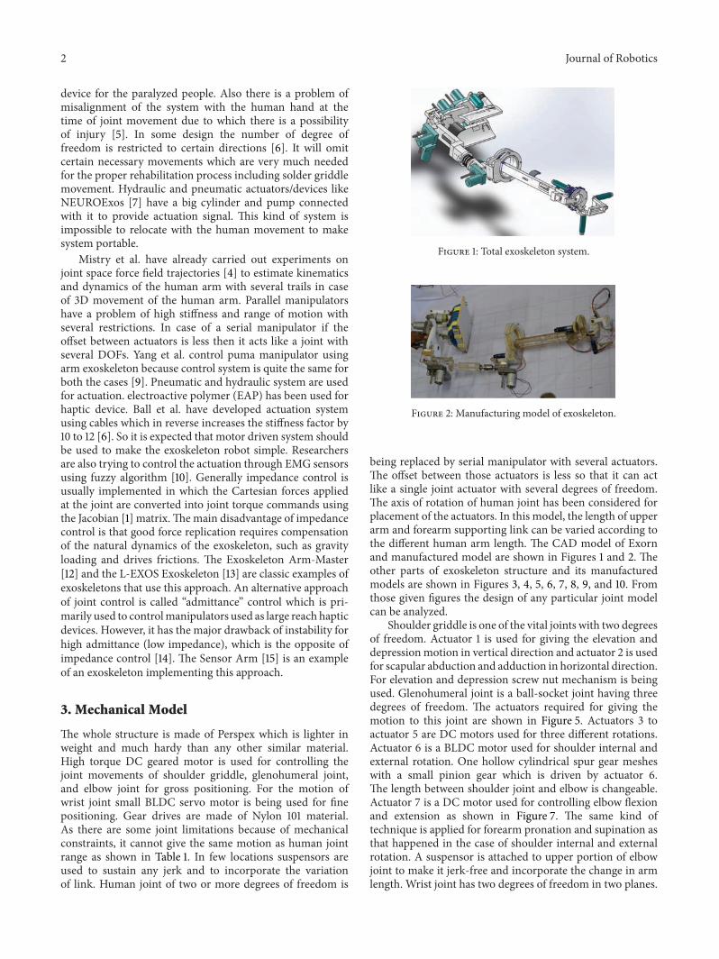
Figure 2 Manufacturing model of exoskeleton
being replaced by serial manipulator with several actuatorsThe offset between those actuators is less so that it can actlike a single joint actuator with several degrees of freedomThe axis of rotation of human joint has been considered forplacement of the actuators In this model the length of upperarm and forearm supporting link can be varied according tothe different human arm length The CAD model of Exornand manufactured model are shown in Figures 1 and 2 Theother parts of exoskeleton structure and its manufacturedmodels are shown in Figures 3 4 5 6 7 8 9 and 10 Fromthose given figures the design of any particular joint modelcan be analyzed
Shoulder griddle is one of the vital joints with two degreesof freedom Actuator 1 is used for giving the elevation anddepressionmotion in vertical direction and actuator 2 is usedfor scapular abduction and adduction in horizontal directionFor elevation and depression screw nut mechanism is beingused Glenohumeral joint is a ball-socket joint having threedegrees of freedom The actuators required for giving themotion to this joint are shown in Figure 5 Actuators 3 toactuator 5 are DC motors used for three different rotationsActuator 6 is a BLDC motor used for shoulder internal andexternal rotation One hollow cylindrical spur gear mesheswith a small pinion gear which is driven by actuator 6The length between shoulder joint and elbow is changeableActuator 7 is a DC motor used for controlling elbow flexionand extension as shown in Figure 7 The same kind oftechnique is applied for forearm pronation and supination asthat happened in the case of shoulder internal and externalrotation A suspensor is attached to upper portion of elbowjoint to make it jerk-free and incorporate the change in armlength Wrist joint has two degrees of freedom in two planes
Journal of Robotics 3
Scapular abduction and adduction
Horizontal abduction and adduction
Elevation and depression of shoulder griddle
Conversion of rotational motion into linear motion
through screw jack
Actuator 2Suspensor
Actuator 1
Figure 3 Shoulder griddle joint model
Scapular abduction and adduction
Horizontalabduction and
adduction
Conversion of rotational motion into linear motion through screw jack
Actuator 1
DC geared motor
Figure 4 Manufactured model of shoulder griddle
(A) Horizontal abduction and adduction(B) Vertical abduction and adduction(C) Forward flexion and extension(D) External and internal rotation
Actuator 3
Actuator 4Actuator 5
Actuator 6
Adjustment for variable upper arm length
Suspensor
A
BC
D
Figure 5 Glenohumeral joint model
adduction
DC geared motor used for forward flexion and
DC geared motor used for vertical abduction and
Variable adjustable upper arm structure
extension
Figure 6 Manufactured model of glenohumeral joint
Adjustment for variable upper arm length
Shoulder external and internal rotation
Elbow flexion and extension
Hand rest for forearm
Suspensor
Actuator 7
Figure 7 Elbow joint model
Actuators 9 and 10 are used for providing thosemotions Herewe can see that all the actuators are dedicated to give themotion in all directions according to the differentmovementsof human arm as shown in Figure 11
Weight of the Prototype 5 kg
Specification of the DC Geared Motor
Weightmdash500 gm
Speedmdash10 rpm
Torquemdash100 kg-cm at 4 ampere (Max)
Specification of BLDC Motor
Company-Faulhaber
Weightmdash500 gm
Speedmdash10 rpm
Torquemdash100 kg-cm at 4 ampere (Max)
Gears are made up of Nylon 101 Structures are usedfor twisting moment at human elbow and wrist with thehelp of gear arrangement which provide better flexibility andstrength
4 Journal of Robotics
Gear arrangement for shoulder external and internal rotation
DC geared motor for elbow flexion and
BLDC motor
Suspensor
Forearm structure
extension
Figure 8 Manufactured model of elbow joint
Adjustment for variable forearm
Elbow pronation and supination
Palm flexion and extension
Palm radial andulnar deviation
Actuator 8
Actuator 9
Actuator 10
Hand rest
length
Figure 9 Wrist joint model
Specification of Nylon 101
Tensile strength 79289709Nm2
Mass density 1150Kgm3
Elastic modulus 1000000000Nm2
Yield strength 60000000Nm2
Turn ratio at the elbow joint 35 8Turn ratio at wrist joint 15 4
At the shoulder joint bush is used to provide the supportto the joint motor axis It is made up of brass to reducethe wear and tear between perspex and motor spindle Onecylindrical rod of the same material moves inside the bushand provides the support to the other end of structure at thetime of joint flexion and extension
The whole body of Exorn is made up of perspex It ishardy and elastic It gives less weight in respect to aluminumPerplex sheet is cut into different pieces and attached witheach other through industrial gum and nut (M4 thread)Three different thickness perspex sheets have been used forthe structureHigherwidth is used at the arm structure to givebetter support and the lower one is used for hand structure
Type 1mdashWidth 5mmType 2mdashWidth 10mmType 3mdashWidth 20mm
BLDC motor used for elbow pronation and supination
BLDC motor used for palm flexion
BLDC motor used for palm radial and
ulnar deviation
Hand rest
and extension
Figure 10 Manufactured model of wrist joint
Specification of Perspex (TM) GS Acrylic Cast Sheet
Tensile strength 75000000Nm2
Density 1190Kgm3
Size of the Exoskeleton The size of the exoskeleton (approxi-mately 9673 cm) has been taken as per the standard length ofa human arm and it can be varied from person to person
Length of shoulder griddle 0129119867Length of upper arm 0186119867Length of forearm 0146119867Length of hand 0108119867
Here 119867 is defined as the height of the human arm and ifwe consider the height of a standard human as 170 cm thelength will be approximately 9673 cm Obviously the lengthof human arm is different from person to person But as wehave made a physical system we have taken the standardlength But the system has a provision so that it is wearable toall the people of variable arm lengthwhich has been discussedin the portion of mechanical model
4 Kinematic Analysis of Exorn
Kinematic model of Exorn is designed according to theanthropometric data of standard human arm The mechani-cal structure is such that it can align with human arm and canprovide the desirable joint motion Some mechanical barrieris located to restrict the joint from hyperextension Here theforward kinematics of the whole system is discussed whichprovides the end point position and orientation due to severaljointmotions It is basically acting as a seriesmanipulatorThekinematic relation of a manipulator is represented by = 119869 120579
Journal of Robotics 5
Elevation
Depression
Extension
Flexion
Abduction
Adduction
Flexion
Extension
Horizontal abduction
Horizontaladduction
Lateral
Medical rotation
Flexion
ExtensionSupination Pronation
Extension
Flexion
Ulnar deviation Radial deviation0
0
0
0
0
0
0 0
0
0
0∘
15∘
15∘
40∘ 180∘
180∘
135∘
20∘
20∘
20∘
45∘
45∘
60∘60∘
80∘
80∘
10∘
80∘ 90∘
140∘
Figure 11 Different motions of human arm
is the119898 dimensional vector specifying the task velocityof end effector 120579 is 119899 dimensional vector representing thejoint velocity 119869 is the119898 by 119899 Jacobianmatrix For a redundantmanipulator 119899 is always greater than 119898 Here the kinematicredundancy is 3
41 D-HParameter of the 3DModel To do kinematic analysisof the whole system it is essential to derive D-H parameterof the whole system The coordinate system of the wholestructure is shown in Figure 12 The coordinate structure ofthe exoskeleton system is based on 3D conceptual modelof Exorn D-H parameters of the structure are shown inTable 2 It is essential to calculate the position and orientationof the end point in 3D space with respect to the referencecoordinate
42 Transformation Matrix Generation For getting the posi-tion and orientation of the end point of Exorn systemhomogeneous transformation matrix is considered Eachhomogeneous transformation matrix was calculated for theposition and orientation of present frame with respect to theprevious frame It is a 4 times 4 matrix The column 119894minus1119889
119894is
position of the end point and 119894minus1119877119894is the orientation of end
point in 3D space The transformation matrix is 119894minus1119860119894
119894minus1119860119894= [
119894minus1119877119894
119894minus1
119889119894
0 1]
4times4
(1)
The homogeneous matrix is being explained as119894minus1119860119894= 119863119911119894minus1119889119894
lowast 119877119911119894minus1120579119894
lowast 119863119909119894minus1119886119894
lowast 119877119909119894minus1120572119894
=
[[[
[
cos 120579119894minus sin 120579
119894cos120572119894
sin 120579119894sin120572119894
119886119894cos 120579119894
sin 120579119894
cos 120579119894cos120572119894minus cos 120579
119894sin120572119894119886119894sin 120579119894
0 sin120572119894
cos120572119894
119889119894
0 0 0 1
]]]
]
119894minus1119889119894= [
[
119886119894cos 120579119894
119886119894sin 120579119894
119889119894
]
]
119894minus1119877119894= [
[
cos 120579119894minus sin 120579
119894cos120572119894
sin 120579119894sin120572119894
sin 120579119894
cos 120579119894cos120572119894minus cos 120579
119894sin120572119894
0 sin120572119894
cos120572119894
]
]
(2)
For calculating the homogeneous matrix due to 10 degrees offreedom the 10 homogeneous matrixes are been multipliedsequentially The final matrix is 119879 which is represented as
119879 =01198601times11198602times21198603times31198604times41198605sdot sdot sdot times911986010 (3)
The calculation can be made easy by dividing the totalmultiplication into two parts such that 119879 =
01198605times511986011 As
it is a 10 DOF system Finally 119879 matrix of the end point ofExorn is represented with respect to reference and its upper 3values of last column are position vector of end point relatedto world frame
6 Journal of Robotics
a1a2
a3
a4
a5
a7
d2
d3
d5
d6
d7
d8d9
d10
x1x2
x3
x4
x5
x6
x7
x8
x9x10
x11
y1
y2
y3y4
y6
y7
y8
y9
y10y11
z2
z3
z4z5
z6
z7
z8
z9
z10 z11
Figure 12 Coordinate system of 3D model
5 Simulation Model of Human Arm
A human armmodel is being made in Simulink to determinethe required torque to move a joint The length of upperarm lower arm and hand is considered according to theanthropometric data of standard human arm The inertiamatrix of each segment is determined according to the massof that segment and length of the centre of gravity fromthe proximal end as per Table 3 In Simulink it is possibleto provide motions in terms of velocity to joint actuatorand from the joint sensor torque level change is notedThe Simulink model of human arm is shown in Figure 13Maximum amount of torque is needed to move those jointswhich are in vertical direction Here only joint motionrelated to shoulder elbow and wrist flexion and extensionis considered Next those internal and external rotations are
Table 1 Comparative study between joints of human arm andExorn
Actuatornumber Movement Human joint
range (Deg)Exorn range
(deg)Shoulder griddle movements
Actuator 1 Elevation 40 30Depression 10 10
Actuator 2 Scapular abduction 20 20Scapular adduction 15 15
Shoulder joint movements
Actuator 3 Horizontal abduction 135 90Horizontal adduction 45 45
Actuator 4 Vertical abduction 180 160Vertical adduction 20 0
Actuator 5 Forward flexion 180 90Forward extension 60 60
Actuator 6 External rotation 90 90Internal rotation 20 20
Elbow joint movements
Actuator 7 Elbow flexion 140 120Elbow extension 0 0
Actuator 8 Forearm pronation 90 90Forearm supination 80 80
Wrist joint movements
Actuator 9 Palm radial deviation 15 10palm ulnar deviation 45 30
Actuator 10 Palm flexion 80 80Palm extension 80 80
Table 2 D-H parameter of Exorn
119886119894(cm) 120572
119894(deg) 119889
119894(cm) 120579
119894(deg)
10 90 0 Θ1
12 0 5 Θ2
6 90 2 Θ3
3 minus90 0 Θ4
31 0 minus25 Θ5
0 90 6 Θ6
3 0 35 Θ7
0 90 25 Θ8
0 minus90 4 Θ9
0 0 8 Θ10
being taken care of In exoskeleton system those motionscannot be controlled from the fixed end due to its twistingtypeTherefore the end effector should be rotatedwith respectto fixed end
The Simulink blocks used for making the human armmodel are shown in Figures 14 and 15 A joint actuator blockis connected to provide the actuation signal and joint sensorblock is attached to measure the computed torque In orderto make a joint with several DOFs several bodies of zeromass and zero length with actuator block of different axis of
Journal of Robotics 7
(a) (b)
Figure 13 (a) Simulink model of human hand (b) human hand position at zero position
Conn1Conn1
Conn1Conn1
Conn2 Conn2
Conn2
Conn2
Conn3
Conn3
Conn3
Conn4
Conn4Conn5
Out1
Out1
Out2
Out3
Out3Out2
Ground Weld Body2
To workspace
To workspace1
To workspace2
Subsystem
Subsystem3 Subsystem6 Subsystem9
Shoulder joint Elbow jointWrist joint
Display3 Display9 Display12
Finger
In1 out1 In1 out1 In1 out1
CS1 CS17
x
y
z
B F
Figure 14 Human arm model in Simulink
rotations are connected Here in Figure 15 body 1 and body2 have zero length and zero mass Only body 3 is the actualbody It is under every human arm joint Body sensor isattached at the end point to get points in 3D space at the timeof motion
6 Embedded System
A PC based control system is being developed to provideparticular orthopedic lesson First of all command signalfrom PC is transmitted to the master controller Mastercontroller activates those joints which are needed to achievethe desired motion It sends the command bits in a packagethrough serial communication Enable signal is being sent to
all the local controllers but only few are being activated as percommand with the help of multiprocessor communicationtechnique All the motor controllers are connected in adaisy chain network that means 119879
119909and 119877
119909pins of master
controller are connected to all 119877119909and 119879
119909pins of each
controller respectively Each controller has a particular nodeas an activating signal When the master controller sends theactivation signal the particular motor controller with thatparticular node is activated
The interfacing circuit between microcontroller andmotor driver is shown in Figures 16(a) and 16(b) Driver IChas 4 input pins and 2 enable pins Here all the inputs pins andenable pins are connecting to port 0 and port 1 Here all theenable pins are sorted and connected through one port pin
8 Journal of Robotics
CS1 CS15 CS1 CS15 CS1 CS15B F B FB F1
12
2
3
Conn2 Conn3Body1 Body2 Body3
Out1Out2 Out3
Signal2Signal2Signal2
Revolute1 Revolute2 Revolute3
Joint actuatorJoint actuator1 Joint actuator2Joint sensor1 Joint sensor2 Joint sensor3
Shoulder vertical motion Shoulder forward flexion Shoulder horizontal motion
Figure 15 Block diagram below each human joint
(a)
Junction circuit 1P89V51RD2 7805 IC
7805 IC Max232DB-9
DB-9
Local controller for DC motor
Local controller for BLDC motor
DC motor driver circuit
Junction circuit 2
7805 IC
IN 4007L298
(b)
Figure 16 (a) Schematic design of interfacing circuit between microcontroller and motor driver (b) Developed interfacing circuit ofmicrocontroller
In this case all the enable pins become activated at one timeSo the motion of motor can be controlled by changing driverinputsThose inputs are amplified from 5V to 12V to run themotor in clockwise and anticlockwise manner (Figure 17) Asshown in the figure one dedicated 7805 IC (Voltage regulator)is connected tomicrocontroller for 5V power supply A serialIC MAX232 is connected to the microcontroller to convert
the RS232rsquos signals to TTL voltage levels that is acceptable to8051 microcontroller 119879
119909and 119877
119909pins
A bidirectional H bridgeDC motor control circuit isshown in Figures 17(a) and 17(b) The circuit is based onthe IC L298 from ST Microelectronics L298 It is a dual fullbridge driver that has a wide operating voltage range andcan handle load currents up to 3A The IC also features low
Journal of Robotics 9
Out In
sum
sum
MT2
100120583F
1 120583F
1 120583F
10120583F
CN5
CN6
1K 1K
1K1K
L298
REF7805
D1
D2
D3
D4
D5
D6 D7
D8
D9D10
D11 D12
R1 R2
R3R4
C1
C2
C3C4
(a)
Motor driver L298
H bridge driver
Power supply
(b)
Figure 17 (a) Schematic design of motor driver circuit (b) Developed motor driver circuit
Table 3 Segment mass and lengths of human arm [8]
Segment Segment masstotal body mass Centre of masssegment length Radius of gyrationsegment lengthProximal Distal CM Proximal Distal
Hand 0006 0506 0494 0297 0587 0577Forearm 0016 0430 0570 0303 0526 0647Upperarm 0028 0436 0564 0322 0542 0645Forearm and Hand 0022 0682 0318 0468 0827 0565Total arm 0050 0530 0470 0368 0645 0596
saturation voltage and over temperature protection In thecircuit diodes D1 to D8 are protection diodesThe state of themotor depends on the logic level of the pins 5 6 and 7 and10 11 and 12 and it is described in the table shown below thecircuit diagram
The diodes D1 to D4 and D5 to D8 provide a safer pathfor the back emf from the motor to dissipate and thus itprotects the corresponding bipolar transistors from damageThe input pins from motor driver are being connected tothe microcontroller port pins When the enable pins of thedriver pin are active then the input signal of the motor driveris amplified to 12 volt and sent to the motor According tothe configuration of port pins motor moves in clockwise oranticlockwise direction
In case of BLDCmotor controller every controller has itsparticular node for distinguishing one from the other It ispossible to control the speed of the motor either by varyingthe voltage supplied to it or by sending the serial command toit The speed of the motor is controlled by sending a string ofcommand to the BLDCmotor controller serially Also there isan encoder inside the BLDCmotor for getting the angle valuesimultaneously in a feedback loop
All the supply voltages are being bypassed through thosejunction circuits Actually all voltage sources are being sortedA 7812 IC voltage regulator is used to convert the 24Vinto 12V DC supply When the diode connected in junctioncircuit is in forward bias it sends the power supply to alldriver circuits but in the opposite case current from driver
10 Journal of Robotics
No
Serial communication configuration
Command comes from PC
GUI open
Serial port start
Serial port configuration
Commands send to the BLDC controller
Interrupt control
Select direction
Select BLDC motor
Send command to motor
Serial portclose
Select speed
DC motor controller
Motor moves
Formation of command package
Can be applied for all motors
SBUF Move motor 1 clockwise
SBUF Move motor 1 anticlockwise
SBUF Move motor 1 stop
Yes
Yes
Yes
No
No
CWCC
= A
= B
= X
Figure 18 Flow chart for PC based control
circuit cannot be sent to the controller circuit The flow chart(Figure 18) is showing the logic behind the algorithm
7 Graphical User Interface Model of Exorn v1
A proper Graphical User Interface (Figure 19) has beendeveloped for controlling all the motions serially through PCbased system It is being designed in Microsoft visual studioplatformThewholeGUImodel is divided into four divisionsFirst one is the configuration of serial communication whereuser has to select the particular COM port and baud rateIt has two buttons for opening and closing of COM portAfter opening of COM port any command can be sent to
the serial portThere are three divisions regarding themotionof human joint for proper treatment Here only one controlcan be selected out of three options Selection of one optionwill freeze the others The flow chart behind the GUI modelis shown in Figure 20
71 Orthopedic Lessons There are some movements whichare generally prescribed by different doctors for strokepatients for different problems All the motions are stored inmemory After selecting somemotion the patient presses thestart button and a command will be sent through serially fortaking proper action It will be updated with time accordingto orthopedic doctor advice
Journal of Robotics 11
Figure 19 GUI model
Serial communication and
configuration
Orthopaedic lessonsIsolateral exercises Angle oriented control
M1
Select BAUD
Select COM port
SpeedCW
CC
M2 Speed CW
CC
SpeedCW
CC
Arm movement
Elbow movement
Forearm movement
Wrist movement
Elevation and depression of shoulder griddle
Scapular abduction and adduction of shoulder griddle
Horizontal abduction and adduction of shoulder joint
Flexion and extension of wrist
M10
Figure 20 Flow chart of GUI model
72 Isolateral Exercises In isolateral exercises there are somepredefined exercises which are standard motions of all jointsof human arm Patients can follow those exercises so that theirmuscle rigidity becomes less After each selection a commandis being sent serially to master controller Master controlleralways takes care of proper actions
73 Angle Oriented Control In this configuration each jointis controlled in clockwise or anticlockwise manner withdifferent speedMore than one joint can be governed throughitWhen user selects jointmotions then a frame of commandbit serially sends with a start and stop bit to distinguish
between different commands User has to write the requiredspeed beside the box of direction of rotation In case twomotions are contradictory then the controller does not allowthat motion It is already preprogrammed in the controller
8 Predefined Control System
It is a predefined control (Figure 21) Already a vast scheduleof exercise modules is to be loaded in the memory Whensomeone wants to perform a task it is being sent to thecontroller through a manual switch or PC Master controllerwill generate a reference trajectory for that particular task
12 Journal of Robotics
PCandGUI
Master controller
Local controller
1H bridge
circuitDriver L298
Feedback
Exorn joint 1
Local controller
10H bridge circuit
Driver L298
Feedback
Exorn joint 10
Inverse kinematics
Forward kinematics
1205751205791
12057512057910
120575x
x
xd
120579
12057910
1205791
jminus1
Figure 21 Independent joint control system
0 20 40 60 80 100
0
2
4
6
8
10
Time (s)
Torque versus time
minus2
minus4
Com
pute
d to
rque
(N-m
)
Figure 22 Joint torque graph at shoulder due to flexion andextension
Then it is being sent to the local controller which takes careof that particular trajectory Always there is feedback loopconnected between the system and the master controllerWith the help of resolved motion rate control (Whitney 72)approach each joint can be controlled in an independent wayAccording to forward kinematics the kinematic model can beexpressed using the equation
120575119909 = 119869 (120579) 120575120579 (4)
Outside the singularities the inverse kinematics can beexpressed as
120575120579 = 119869minus1(120579) 120575119909 (5)
0 20 40 60 80 100 120
0
05
1
15
2
25
minus05
minus1
minus15
minus2
Time (s)
Torque versus time
Com
pute
d to
rque
(N-m
)
Figure 23 Joint torque graph at elbow due to elbow flexion andextension
There is a relation between task space and joint space Herethe current position at some angle 120579 can be expressed as
119909 = 119891 (120579) (6)
The desired location in 3D space is defined as 119909119889 So error
between current and desired position can be expressed as
120575119909 = 119909119889minus 119909
120575120579 = 119869minus1(120579) 120575119909
(7)
The next 120579 will be expressed as 1205791015840 = 120579 + 120575120579 In this way 120579value can be increased or decreased in an iterative way so that
Journal of Robotics 13
0 10 20 30 40 50 60 70 80 90005
01
015
02
025
03
035
04
045
Time (s)
Torque versus time
Com
pute
d to
rque
(N-m
)
Figure 24 Joint torque graph at wrist due to flexion and extension
0 10 20 30 40 50 60
0
1
2
3
4
5
6
minus1
minus2
minus3
times10minus3
Time (s)
Torque versus time
Com
pute
d to
rque
(N-m
)
Figure 25 Joint torque graph at elbow due to shoulder internal andexternal rotation
the desired location can be reached The error betweendesired location and current location can be compared usingforward kinematics in a feedback loop
In case of finding inverse kinematics there is a problem ofsingularity So we are imposing damped least square methodfor calculating the inverse kinematics The damped leastsquares solutions are intended to ensure a well-conditionedmatrix for the solution algorithmwhile limiting the size of thesolution vector 120575120579 This is done by adding a diagonal matrix120572119868 to the matrix 119869119869119879 The approximate solution of dampedleast squares method can be expressed as 120575120579 = 119869
+120575119909 where
119869+ can be expressed as the equation given below
119869+= 119869119879(119869119869119879+ 120572119868)minus1
120572 ge 0 (8)
0 20 40 60 80 100 120
0
2
4
6
minus2
minus4
minus6
times10minus3
Time (s)
Torque versus time
Com
pute
d to
rque
(N-m
)
Figure 26 Joint torque graph at wrist due to elbow pronation andsupination
When this equation is used then the solution satisfies
min120575120579
120575119909 minus 1198691205751205792+ 12057221205751205792 (9)
where sdot denotes the Euclidean norm For 120572 = 0 the dampedleast squares solution will become pseudoinverse solutionThen the Jacobian inversematrix will be 119869lowast where 119869lowast becomeexpressed as 119869119879(119869119869119879)minus1
In the damped least squares method the size of errorin the task space is weighed against the size of the resultingsolution For a given 120575119909 the size of the solution vector isdecreased by increasing 120572 However this is done at theexpense of using an approximate solution As 120572 increases sodoes the size of the error in the task space A large 120572 hasthe other benefit of ensuring a well-conditioned matrix forinversion It has been shown that the condition number 119870of the matrix 119875 equiv (119869119869
119879+ 120572119868) is 119870 = (120590
2
1+ 120572)(120590
2
119898+ 120572)
Here 1205901ge 1205902ge 1205903sdot sdot sdot ge 120590
119898ge 0 are the singular values of
the Jacobian matrix It can be seen in this equation that 119870is made arbitrarily close to 1 by increasing 120572 thus ensuringa well-conditioned matrix for inversion even in a singularconfiguration where 120590
119898= 0 Simply stated if one is willing
to give up the exactness of the solution then the size of thejoint rate can be reduced and a well-conditioned matrix forinversion can be ensured by increasing 120572
9 Simulation Results of Torque Level ofGeneral Human Arm
Maximum amount of torque is required to actuate humanjoints in vertical direction Here in Figure 25 the torqueneeded to twist the elbow with respect to shoulder joint isshown Figure 26 is showing the same kind ofmotion in wrist
14 Journal of Robotics
0 200 400 600 800 1000 12000500
1000
0500
1000
minus500
minus1000
minus500
minus1000
(a)
20
20
0
0
minus20
minus20
minus40
minus40
40
minus60
minus60
minus80 500
minus50
x
y z
Untitled fit 1x versus z y
(b)
Figure 27 (a) Outer region covered by Exorn (b) Workspace covered by Exorn
0
minus10
minus20
minus30
minus40
minus5040
3020
100minus10
minus20 0 1020 30
40 5060
70
Figure 28 Motion due to shoulder griddle
006
004
002
0
minus0020
001
002
003
004
005002
0 minus002 minus004minus006 minus008
minus01
Figure 29 Motion due to shoulder griddle glenohumerals andelbow joint movement
joint with respect to the elbow Figures 22 23 24 25 and26 will show torque variation in different joints in verticaldirection because of proper actuation signal From thosebelow graphs max and min torque for joint actuator can bedetermined because it is very much essential to select propermotor
006
004
002
0
minus0020
minus002minus004
minus006minus008
minus010
002
004
006
008
Figure 30 Motion due to shoulder joint and elbow joint movementin vertical direction
003
002
001
0
minus001
minus002
minus0030 minus002 minus004 minus006 minus008 minus01
0
001
002
003
Figure 31 Motion due to glenohumeral joint and elbow jointmovement in horizontal direction
10 Workspace Calculation and Motion due toForward Kinematics
For calculating the workspace of the robotic system aMATLAB code of nested for loop of all DOFs is being takenwith the joint range It will plot all the reachable points ofarm exoskeleton in 3D space Figure 27 is showing the outer
Journal of Robotics 15
region covered by human hand Figures 28 29 30 and 31 areshowing themotion of exoskeletonmodel due to several jointmovements
11 Conclusion
From the above discussion it may be concluded that thedeveloped system is useful for rehabilitation Comparisonsbetween human jointrsquos range and that of Exorn are alreadytabulated in Table 1 and the ranges are quite the same for boththe cases If the portable mechanical structure is attached tothe human arm it can be used as an assistive device for theparalyzed people The 3D model of exoskeleton is alreadybeing developed The model has been fabricated With thehelp of the GUI all the motions can be controlled throughserial communication The developed prototype is underworking condition We would like to build the real system sothat patient can be benefitted
References
[1] J W Krakauer ldquoArm function after stroke from physiology torecoveryrdquo Seminars in Neurology vol 25 no 4 pp 384ndash3952005
[2] T Nef and R Riener ldquoARMinmdashdesign of a novel arm reha-bilitation robotrdquo in Proceedings of the IEEE 9th InternationalConference on Rehabilitation Robotics (ICORR rsquo05) pp 57ndash60July 2005
[3] S J Ball I E Brown and S H Scott ldquoMEDARM a rehabilita-tion robot with 5DOF at the shoulder complexrdquo in Proceedingsof the IEEEASME International Conference on Advanced Intel-ligent Mechatronics (AIM rsquo07) September 2007
[4] M Mistry P Mohajerian and S Schaal ldquoArm movementexperiments with joint space force fields using an exoskeletonrobotrdquo in Proceedings of the IEEE 9th International Conferenceon Rehabilitation Robotics (ICORR rsquo05) pp 408ndash413 July 2005
[5] A Schiele and F C T van der Helm ldquoKinematic design toimprove ergonomics in human machine interactionrdquo IEEETransactions on Neural System and Rehabilitation vol 14 no4 pp 1534ndash4320 2006
[6] S J Ball I E Brown and S H Scott ldquoA planar 3DOF roboticexoskeleton for rehabilitation and assessmentrdquo in Proceedingsof the 29th Annual International Conference of IEEE-EMBSEngineering in Medicine and Biology Society (EMBC rsquo07) pp4024ndash4027 August 2007
[7] I Sardellitti E Cattin S Roccella et al ldquoDescription char-acterization and assessment of a bio-inspired shoulder joint-first link robot for neuro-robotic applicationsrdquo in Proceedings ofthe 1st IEEERAS-EMBS International Conference on BiomedicalRobotics andBiomechatronics (BioRob rsquo06) pp 112ndash117 February2006
[8] Source-winter Biomechanics and Motor Control of HumanMotion ISBN-978-0470398180 2010
[9] C-J Yang B Niu J-F Zhang and Y Chen ldquoDifferent structurebased control system of the PUMA manipulator with an armexoskeletonrdquo in Proceedings of the IEEE Conference on RoboticsAutomation and Mechatronics pp 572ndash577 December 2004
[10] K Kiguchi T Tanaka K Watanabe and T Fukuda ldquoExoskele-ton for human upper-limb motion supportrdquo in Proceedings ofthe IEEE International Conference on Robotics and Automationpp 2206ndash2211 September 2003
[11] T H Massie and K J Salisbury ldquoPHANToM haptic interfacea device for probing virtual objectsrdquo in Proceedings of theInternational Mechanical Engineering Congress and Expositionpp 295ndash299 November 1994
[12] CCarignan andKCleary ldquoClosed-loop force control for hapticsimulation of virtual environmentsrdquo The Electronic Journal ofHaptics Research vol 2 no 2 pp 1ndash14 2000
[13] A Frisoli F Rocchi S Marcheschi A Dettori F Salsedo andM Bergamasco ldquoA new force-feedback arm exoskeleton forhaptic interaction in virtual environmentsrdquo in Proceedings ofthe First Joint Eurohaptics Conference and Symposium on HapticInterfaces for Virtual Environment and Teleoperator Systems pp195ndash201 2005
[14] D Lawrence ldquoImpedance control stability properties in com-mon implementationsrdquo in Proceedings of the IEEE InternationalConference on Robotics and Automation pp 1185ndash1190 1988
[15] A Nakai Y Kunii H Hashimoto and F Harashima ldquoArmtype haptic human interface sensor armrdquo in Proceedings of theInternational Conference on Artificial Reality and Tele-Existence(ICAT) pp 77ndash84 Tokyo Japan December 1997
International Journal of
AerospaceEngineeringHindawi Publishing Corporationhttpwwwhindawicom Volume 2014
RoboticsJournal of
Hindawi Publishing Corporationhttpwwwhindawicom Volume 2014
Hindawi Publishing Corporationhttpwwwhindawicom Volume 2014
Active and Passive Electronic Components
Control Scienceand Engineering
Journal of
Hindawi Publishing Corporationhttpwwwhindawicom Volume 2014
International Journal of
RotatingMachinery
Hindawi Publishing Corporationhttpwwwhindawicom Volume 2014
Hindawi Publishing Corporation httpwwwhindawicom
Journal ofEngineeringVolume 2014
Submit your manuscripts athttpwwwhindawicom
VLSI Design
Hindawi Publishing Corporationhttpwwwhindawicom Volume 2014
Hindawi Publishing Corporationhttpwwwhindawicom Volume 2014
Shock and Vibration
Hindawi Publishing Corporationhttpwwwhindawicom Volume 2014
Civil EngineeringAdvances in
Acoustics and VibrationAdvances in
Hindawi Publishing Corporationhttpwwwhindawicom Volume 2014
Hindawi Publishing Corporationhttpwwwhindawicom Volume 2014
Electrical and Computer Engineering
Journal of
Advances inOptoElectronics
Hindawi Publishing Corporation httpwwwhindawicom
Volume 2014
The Scientific World JournalHindawi Publishing Corporation httpwwwhindawicom Volume 2014
SensorsJournal of
Hindawi Publishing Corporationhttpwwwhindawicom Volume 2014
Modelling amp Simulation in EngineeringHindawi Publishing Corporation httpwwwhindawicom Volume 2014
Hindawi Publishing Corporationhttpwwwhindawicom Volume 2014
Chemical EngineeringInternational Journal of Antennas and
Propagation
International Journal of
Hindawi Publishing Corporationhttpwwwhindawicom Volume 2014
Hindawi Publishing Corporationhttpwwwhindawicom Volume 2014
Navigation and Observation
International Journal of
Hindawi Publishing Corporationhttpwwwhindawicom Volume 2014
DistributedSensor Networks
International Journal of
2 Journal of Robotics
device for the paralyzed people Also there is a problem ofmisalignment of the system with the human hand at thetime of joint movement due to which there is a possibilityof injury [5] In some design the number of degree offreedom is restricted to certain directions [6] It will omitcertain necessary movements which are very much neededfor the proper rehabilitation process including solder griddlemovement Hydraulic and pneumatic actuatorsdevices likeNEUROExos [7] have a big cylinder and pump connectedwith it to provide actuation signal This kind of system isimpossible to relocate with the human movement to makesystem portable
Mistry et al have already carried out experiments onjoint space force field trajectories [4] to estimate kinematicsand dynamics of the human arm with several trails in caseof 3D movement of the human arm Parallel manipulatorshave a problem of high stiffness and range of motion withseveral restrictions In case of a serial manipulator if theoffset between actuators is less then it acts like a joint withseveral DOFs Yang et al control puma manipulator usingarm exoskeleton because control system is quite the same forboth the cases [9] Pneumatic and hydraulic system are usedfor actuation electroactive polymer (EAP) has been used forhaptic device Ball et al have developed actuation systemusing cables which in reverse increases the stiffness factor by10 to 12 [6] So it is expected that motor driven system shouldbe used to make the exoskeleton robot simple Researchersare also trying to control the actuation through EMG sensorsusing fuzzy algorithm [10] Generally impedance control isusually implemented in which the Cartesian forces appliedat the joint are converted into joint torque commands usingthe Jacobian [1] matrixThemain disadvantage of impedancecontrol is that good force replication requires compensationof the natural dynamics of the exoskeleton such as gravityloading and drives frictions The Exoskeleton Arm-Master[12] and the L-EXOS Exoskeleton [13] are classic examples ofexoskeletons that use this approach An alternative approachof joint control is called ldquoadmittancerdquo control which is pri-marily used to controlmanipulators used as large reach hapticdevices However it has the major drawback of instability forhigh admittance (low impedance) which is the opposite ofimpedance control [14] The Sensor Arm [15] is an exampleof an exoskeleton implementing this approach
3 Mechanical Model
The whole structure is made of Perspex which is lighter inweight and much hardy than any other similar materialHigh torque DC geared motor is used for controlling thejoint movements of shoulder griddle glenohumeral jointand elbow joint for gross positioning For the motion ofwrist joint small BLDC servo motor is being used for finepositioning Gear drives are made of Nylon 101 materialAs there are some joint limitations because of mechanicalconstraints it cannot give the same motion as human jointrange as shown in Table 1 In few locations suspensors areused to sustain any jerk and to incorporate the variationof link Human joint of two or more degrees of freedom is
Figure 1 Total exoskeleton system
Figure 2 Manufacturing model of exoskeleton
being replaced by serial manipulator with several actuatorsThe offset between those actuators is less so that it can actlike a single joint actuator with several degrees of freedomThe axis of rotation of human joint has been considered forplacement of the actuators In this model the length of upperarm and forearm supporting link can be varied according tothe different human arm length The CAD model of Exornand manufactured model are shown in Figures 1 and 2 Theother parts of exoskeleton structure and its manufacturedmodels are shown in Figures 3 4 5 6 7 8 9 and 10 Fromthose given figures the design of any particular joint modelcan be analyzed
Shoulder griddle is one of the vital joints with two degreesof freedom Actuator 1 is used for giving the elevation anddepressionmotion in vertical direction and actuator 2 is usedfor scapular abduction and adduction in horizontal directionFor elevation and depression screw nut mechanism is beingused Glenohumeral joint is a ball-socket joint having threedegrees of freedom The actuators required for giving themotion to this joint are shown in Figure 5 Actuators 3 toactuator 5 are DC motors used for three different rotationsActuator 6 is a BLDC motor used for shoulder internal andexternal rotation One hollow cylindrical spur gear mesheswith a small pinion gear which is driven by actuator 6The length between shoulder joint and elbow is changeableActuator 7 is a DC motor used for controlling elbow flexionand extension as shown in Figure 7 The same kind oftechnique is applied for forearm pronation and supination asthat happened in the case of shoulder internal and externalrotation A suspensor is attached to upper portion of elbowjoint to make it jerk-free and incorporate the change in armlength Wrist joint has two degrees of freedom in two planes
Journal of Robotics 3
Scapular abduction and adduction
Horizontal abduction and adduction
Elevation and depression of shoulder griddle
Conversion of rotational motion into linear motion
through screw jack
Actuator 2Suspensor
Actuator 1
Figure 3 Shoulder griddle joint model
Scapular abduction and adduction
Horizontalabduction and
adduction
Conversion of rotational motion into linear motion through screw jack
Actuator 1
DC geared motor
Figure 4 Manufactured model of shoulder griddle
(A) Horizontal abduction and adduction(B) Vertical abduction and adduction(C) Forward flexion and extension(D) External and internal rotation
Actuator 3
Actuator 4Actuator 5
Actuator 6
Adjustment for variable upper arm length
Suspensor
A
BC
D
Figure 5 Glenohumeral joint model
adduction
DC geared motor used for forward flexion and
DC geared motor used for vertical abduction and
Variable adjustable upper arm structure
extension
Figure 6 Manufactured model of glenohumeral joint
Adjustment for variable upper arm length
Shoulder external and internal rotation
Elbow flexion and extension
Hand rest for forearm
Suspensor
Actuator 7
Figure 7 Elbow joint model
Actuators 9 and 10 are used for providing thosemotions Herewe can see that all the actuators are dedicated to give themotion in all directions according to the differentmovementsof human arm as shown in Figure 11
Weight of the Prototype 5 kg
Specification of the DC Geared Motor
Weightmdash500 gm
Speedmdash10 rpm
Torquemdash100 kg-cm at 4 ampere (Max)
Specification of BLDC Motor
Company-Faulhaber
Weightmdash500 gm
Speedmdash10 rpm
Torquemdash100 kg-cm at 4 ampere (Max)
Gears are made up of Nylon 101 Structures are usedfor twisting moment at human elbow and wrist with thehelp of gear arrangement which provide better flexibility andstrength
4 Journal of Robotics
Gear arrangement for shoulder external and internal rotation
DC geared motor for elbow flexion and
BLDC motor
Suspensor
Forearm structure
extension
Figure 8 Manufactured model of elbow joint
Adjustment for variable forearm
Elbow pronation and supination
Palm flexion and extension
Palm radial andulnar deviation
Actuator 8
Actuator 9
Actuator 10
Hand rest
length
Figure 9 Wrist joint model
Specification of Nylon 101
Tensile strength 79289709Nm2
Mass density 1150Kgm3
Elastic modulus 1000000000Nm2
Yield strength 60000000Nm2
Turn ratio at the elbow joint 35 8Turn ratio at wrist joint 15 4
At the shoulder joint bush is used to provide the supportto the joint motor axis It is made up of brass to reducethe wear and tear between perspex and motor spindle Onecylindrical rod of the same material moves inside the bushand provides the support to the other end of structure at thetime of joint flexion and extension
The whole body of Exorn is made up of perspex It ishardy and elastic It gives less weight in respect to aluminumPerplex sheet is cut into different pieces and attached witheach other through industrial gum and nut (M4 thread)Three different thickness perspex sheets have been used forthe structureHigherwidth is used at the arm structure to givebetter support and the lower one is used for hand structure
Type 1mdashWidth 5mmType 2mdashWidth 10mmType 3mdashWidth 20mm
BLDC motor used for elbow pronation and supination
BLDC motor used for palm flexion
BLDC motor used for palm radial and
ulnar deviation
Hand rest
and extension
Figure 10 Manufactured model of wrist joint
Specification of Perspex (TM) GS Acrylic Cast Sheet
Tensile strength 75000000Nm2
Density 1190Kgm3
Size of the Exoskeleton The size of the exoskeleton (approxi-mately 9673 cm) has been taken as per the standard length ofa human arm and it can be varied from person to person
Length of shoulder griddle 0129119867Length of upper arm 0186119867Length of forearm 0146119867Length of hand 0108119867
Here 119867 is defined as the height of the human arm and ifwe consider the height of a standard human as 170 cm thelength will be approximately 9673 cm Obviously the lengthof human arm is different from person to person But as wehave made a physical system we have taken the standardlength But the system has a provision so that it is wearable toall the people of variable arm lengthwhich has been discussedin the portion of mechanical model
4 Kinematic Analysis of Exorn
Kinematic model of Exorn is designed according to theanthropometric data of standard human arm The mechani-cal structure is such that it can align with human arm and canprovide the desirable joint motion Some mechanical barrieris located to restrict the joint from hyperextension Here theforward kinematics of the whole system is discussed whichprovides the end point position and orientation due to severaljointmotions It is basically acting as a seriesmanipulatorThekinematic relation of a manipulator is represented by = 119869 120579
Journal of Robotics 5
Elevation
Depression
Extension
Flexion
Abduction
Adduction
Flexion
Extension
Horizontal abduction
Horizontaladduction
Lateral
Medical rotation
Flexion
ExtensionSupination Pronation
Extension
Flexion
Ulnar deviation Radial deviation0
0
0
0
0
0
0 0
0
0
0∘
15∘
15∘
40∘ 180∘
180∘
135∘
20∘
20∘
20∘
45∘
45∘
60∘60∘
80∘
80∘
10∘
80∘ 90∘
140∘
Figure 11 Different motions of human arm
is the119898 dimensional vector specifying the task velocityof end effector 120579 is 119899 dimensional vector representing thejoint velocity 119869 is the119898 by 119899 Jacobianmatrix For a redundantmanipulator 119899 is always greater than 119898 Here the kinematicredundancy is 3
41 D-HParameter of the 3DModel To do kinematic analysisof the whole system it is essential to derive D-H parameterof the whole system The coordinate system of the wholestructure is shown in Figure 12 The coordinate structure ofthe exoskeleton system is based on 3D conceptual modelof Exorn D-H parameters of the structure are shown inTable 2 It is essential to calculate the position and orientationof the end point in 3D space with respect to the referencecoordinate
42 Transformation Matrix Generation For getting the posi-tion and orientation of the end point of Exorn systemhomogeneous transformation matrix is considered Eachhomogeneous transformation matrix was calculated for theposition and orientation of present frame with respect to theprevious frame It is a 4 times 4 matrix The column 119894minus1119889
119894is
position of the end point and 119894minus1119877119894is the orientation of end
point in 3D space The transformation matrix is 119894minus1119860119894
119894minus1119860119894= [
119894minus1119877119894
119894minus1
119889119894
0 1]
4times4
(1)
The homogeneous matrix is being explained as119894minus1119860119894= 119863119911119894minus1119889119894
lowast 119877119911119894minus1120579119894
lowast 119863119909119894minus1119886119894
lowast 119877119909119894minus1120572119894
=
[[[
[
cos 120579119894minus sin 120579
119894cos120572119894
sin 120579119894sin120572119894
119886119894cos 120579119894
sin 120579119894
cos 120579119894cos120572119894minus cos 120579
119894sin120572119894119886119894sin 120579119894
0 sin120572119894
cos120572119894
119889119894
0 0 0 1
]]]
]
119894minus1119889119894= [
[
119886119894cos 120579119894
119886119894sin 120579119894
119889119894
]
]
119894minus1119877119894= [
[
cos 120579119894minus sin 120579
119894cos120572119894
sin 120579119894sin120572119894
sin 120579119894
cos 120579119894cos120572119894minus cos 120579
119894sin120572119894
0 sin120572119894
cos120572119894
]
]
(2)
For calculating the homogeneous matrix due to 10 degrees offreedom the 10 homogeneous matrixes are been multipliedsequentially The final matrix is 119879 which is represented as
119879 =01198601times11198602times21198603times31198604times41198605sdot sdot sdot times911986010 (3)
The calculation can be made easy by dividing the totalmultiplication into two parts such that 119879 =
01198605times511986011 As
it is a 10 DOF system Finally 119879 matrix of the end point ofExorn is represented with respect to reference and its upper 3values of last column are position vector of end point relatedto world frame
6 Journal of Robotics
a1a2
a3
a4
a5
a7
d2
d3
d5
d6
d7
d8d9
d10
x1x2
x3
x4
x5
x6
x7
x8
x9x10
x11
y1
y2
y3y4
y6
y7
y8
y9
y10y11
z2
z3
z4z5
z6
z7
z8
z9
z10 z11
Figure 12 Coordinate system of 3D model
5 Simulation Model of Human Arm
A human armmodel is being made in Simulink to determinethe required torque to move a joint The length of upperarm lower arm and hand is considered according to theanthropometric data of standard human arm The inertiamatrix of each segment is determined according to the massof that segment and length of the centre of gravity fromthe proximal end as per Table 3 In Simulink it is possibleto provide motions in terms of velocity to joint actuatorand from the joint sensor torque level change is notedThe Simulink model of human arm is shown in Figure 13Maximum amount of torque is needed to move those jointswhich are in vertical direction Here only joint motionrelated to shoulder elbow and wrist flexion and extensionis considered Next those internal and external rotations are
Table 1 Comparative study between joints of human arm andExorn
Actuatornumber Movement Human joint
range (Deg)Exorn range
(deg)Shoulder griddle movements
Actuator 1 Elevation 40 30Depression 10 10
Actuator 2 Scapular abduction 20 20Scapular adduction 15 15
Shoulder joint movements
Actuator 3 Horizontal abduction 135 90Horizontal adduction 45 45
Actuator 4 Vertical abduction 180 160Vertical adduction 20 0
Actuator 5 Forward flexion 180 90Forward extension 60 60
Actuator 6 External rotation 90 90Internal rotation 20 20
Elbow joint movements
Actuator 7 Elbow flexion 140 120Elbow extension 0 0
Actuator 8 Forearm pronation 90 90Forearm supination 80 80
Wrist joint movements
Actuator 9 Palm radial deviation 15 10palm ulnar deviation 45 30
Actuator 10 Palm flexion 80 80Palm extension 80 80
Table 2 D-H parameter of Exorn
119886119894(cm) 120572
119894(deg) 119889
119894(cm) 120579
119894(deg)
10 90 0 Θ1
12 0 5 Θ2
6 90 2 Θ3
3 minus90 0 Θ4
31 0 minus25 Θ5
0 90 6 Θ6
3 0 35 Θ7
0 90 25 Θ8
0 minus90 4 Θ9
0 0 8 Θ10
being taken care of In exoskeleton system those motionscannot be controlled from the fixed end due to its twistingtypeTherefore the end effector should be rotatedwith respectto fixed end
The Simulink blocks used for making the human armmodel are shown in Figures 14 and 15 A joint actuator blockis connected to provide the actuation signal and joint sensorblock is attached to measure the computed torque In orderto make a joint with several DOFs several bodies of zeromass and zero length with actuator block of different axis of
Journal of Robotics 7
(a) (b)
Figure 13 (a) Simulink model of human hand (b) human hand position at zero position
Conn1Conn1
Conn1Conn1
Conn2 Conn2
Conn2
Conn2
Conn3
Conn3
Conn3
Conn4
Conn4Conn5
Out1
Out1
Out2
Out3
Out3Out2
Ground Weld Body2
To workspace
To workspace1
To workspace2
Subsystem
Subsystem3 Subsystem6 Subsystem9
Shoulder joint Elbow jointWrist joint
Display3 Display9 Display12
Finger
In1 out1 In1 out1 In1 out1
CS1 CS17
x
y
z
B F
Figure 14 Human arm model in Simulink
rotations are connected Here in Figure 15 body 1 and body2 have zero length and zero mass Only body 3 is the actualbody It is under every human arm joint Body sensor isattached at the end point to get points in 3D space at the timeof motion
6 Embedded System
A PC based control system is being developed to provideparticular orthopedic lesson First of all command signalfrom PC is transmitted to the master controller Mastercontroller activates those joints which are needed to achievethe desired motion It sends the command bits in a packagethrough serial communication Enable signal is being sent to
all the local controllers but only few are being activated as percommand with the help of multiprocessor communicationtechnique All the motor controllers are connected in adaisy chain network that means 119879
119909and 119877
119909pins of master
controller are connected to all 119877119909and 119879
119909pins of each
controller respectively Each controller has a particular nodeas an activating signal When the master controller sends theactivation signal the particular motor controller with thatparticular node is activated
The interfacing circuit between microcontroller andmotor driver is shown in Figures 16(a) and 16(b) Driver IChas 4 input pins and 2 enable pins Here all the inputs pins andenable pins are connecting to port 0 and port 1 Here all theenable pins are sorted and connected through one port pin
8 Journal of Robotics
CS1 CS15 CS1 CS15 CS1 CS15B F B FB F1
12
2
3
Conn2 Conn3Body1 Body2 Body3
Out1Out2 Out3
Signal2Signal2Signal2
Revolute1 Revolute2 Revolute3
Joint actuatorJoint actuator1 Joint actuator2Joint sensor1 Joint sensor2 Joint sensor3
Shoulder vertical motion Shoulder forward flexion Shoulder horizontal motion
Figure 15 Block diagram below each human joint
(a)
Junction circuit 1P89V51RD2 7805 IC
7805 IC Max232DB-9
DB-9
Local controller for DC motor
Local controller for BLDC motor
DC motor driver circuit
Junction circuit 2
7805 IC
IN 4007L298
(b)
Figure 16 (a) Schematic design of interfacing circuit between microcontroller and motor driver (b) Developed interfacing circuit ofmicrocontroller
In this case all the enable pins become activated at one timeSo the motion of motor can be controlled by changing driverinputsThose inputs are amplified from 5V to 12V to run themotor in clockwise and anticlockwise manner (Figure 17) Asshown in the figure one dedicated 7805 IC (Voltage regulator)is connected tomicrocontroller for 5V power supply A serialIC MAX232 is connected to the microcontroller to convert
the RS232rsquos signals to TTL voltage levels that is acceptable to8051 microcontroller 119879
119909and 119877
119909pins
A bidirectional H bridgeDC motor control circuit isshown in Figures 17(a) and 17(b) The circuit is based onthe IC L298 from ST Microelectronics L298 It is a dual fullbridge driver that has a wide operating voltage range andcan handle load currents up to 3A The IC also features low
Journal of Robotics 9
Out In
sum
sum
MT2
100120583F
1 120583F
1 120583F
10120583F
CN5
CN6
1K 1K
1K1K
L298
REF7805
D1
D2
D3
D4
D5
D6 D7
D8
D9D10
D11 D12
R1 R2
R3R4
C1
C2
C3C4
(a)
Motor driver L298
H bridge driver
Power supply
(b)
Figure 17 (a) Schematic design of motor driver circuit (b) Developed motor driver circuit
Table 3 Segment mass and lengths of human arm [8]
Segment Segment masstotal body mass Centre of masssegment length Radius of gyrationsegment lengthProximal Distal CM Proximal Distal
Hand 0006 0506 0494 0297 0587 0577Forearm 0016 0430 0570 0303 0526 0647Upperarm 0028 0436 0564 0322 0542 0645Forearm and Hand 0022 0682 0318 0468 0827 0565Total arm 0050 0530 0470 0368 0645 0596
saturation voltage and over temperature protection In thecircuit diodes D1 to D8 are protection diodesThe state of themotor depends on the logic level of the pins 5 6 and 7 and10 11 and 12 and it is described in the table shown below thecircuit diagram
The diodes D1 to D4 and D5 to D8 provide a safer pathfor the back emf from the motor to dissipate and thus itprotects the corresponding bipolar transistors from damageThe input pins from motor driver are being connected tothe microcontroller port pins When the enable pins of thedriver pin are active then the input signal of the motor driveris amplified to 12 volt and sent to the motor According tothe configuration of port pins motor moves in clockwise oranticlockwise direction
In case of BLDCmotor controller every controller has itsparticular node for distinguishing one from the other It ispossible to control the speed of the motor either by varyingthe voltage supplied to it or by sending the serial command toit The speed of the motor is controlled by sending a string ofcommand to the BLDCmotor controller serially Also there isan encoder inside the BLDCmotor for getting the angle valuesimultaneously in a feedback loop
All the supply voltages are being bypassed through thosejunction circuits Actually all voltage sources are being sortedA 7812 IC voltage regulator is used to convert the 24Vinto 12V DC supply When the diode connected in junctioncircuit is in forward bias it sends the power supply to alldriver circuits but in the opposite case current from driver
10 Journal of Robotics
No
Serial communication configuration
Command comes from PC
GUI open
Serial port start
Serial port configuration
Commands send to the BLDC controller
Interrupt control
Select direction
Select BLDC motor
Send command to motor
Serial portclose
Select speed
DC motor controller
Motor moves
Formation of command package
Can be applied for all motors
SBUF Move motor 1 clockwise
SBUF Move motor 1 anticlockwise
SBUF Move motor 1 stop
Yes
Yes
Yes
No
No
CWCC
= A
= B
= X
Figure 18 Flow chart for PC based control
circuit cannot be sent to the controller circuit The flow chart(Figure 18) is showing the logic behind the algorithm
7 Graphical User Interface Model of Exorn v1
A proper Graphical User Interface (Figure 19) has beendeveloped for controlling all the motions serially through PCbased system It is being designed in Microsoft visual studioplatformThewholeGUImodel is divided into four divisionsFirst one is the configuration of serial communication whereuser has to select the particular COM port and baud rateIt has two buttons for opening and closing of COM portAfter opening of COM port any command can be sent to
the serial portThere are three divisions regarding themotionof human joint for proper treatment Here only one controlcan be selected out of three options Selection of one optionwill freeze the others The flow chart behind the GUI modelis shown in Figure 20
71 Orthopedic Lessons There are some movements whichare generally prescribed by different doctors for strokepatients for different problems All the motions are stored inmemory After selecting somemotion the patient presses thestart button and a command will be sent through serially fortaking proper action It will be updated with time accordingto orthopedic doctor advice
Journal of Robotics 11
Figure 19 GUI model
Serial communication and
configuration
Orthopaedic lessonsIsolateral exercises Angle oriented control
M1
Select BAUD
Select COM port
SpeedCW
CC
M2 Speed CW
CC
SpeedCW
CC
Arm movement
Elbow movement
Forearm movement
Wrist movement
Elevation and depression of shoulder griddle
Scapular abduction and adduction of shoulder griddle
Horizontal abduction and adduction of shoulder joint
Flexion and extension of wrist
M10
Figure 20 Flow chart of GUI model
72 Isolateral Exercises In isolateral exercises there are somepredefined exercises which are standard motions of all jointsof human arm Patients can follow those exercises so that theirmuscle rigidity becomes less After each selection a commandis being sent serially to master controller Master controlleralways takes care of proper actions
73 Angle Oriented Control In this configuration each jointis controlled in clockwise or anticlockwise manner withdifferent speedMore than one joint can be governed throughitWhen user selects jointmotions then a frame of commandbit serially sends with a start and stop bit to distinguish
between different commands User has to write the requiredspeed beside the box of direction of rotation In case twomotions are contradictory then the controller does not allowthat motion It is already preprogrammed in the controller
8 Predefined Control System
It is a predefined control (Figure 21) Already a vast scheduleof exercise modules is to be loaded in the memory Whensomeone wants to perform a task it is being sent to thecontroller through a manual switch or PC Master controllerwill generate a reference trajectory for that particular task
12 Journal of Robotics
PCandGUI
Master controller
Local controller
1H bridge
circuitDriver L298
Feedback
Exorn joint 1
Local controller
10H bridge circuit
Driver L298
Feedback
Exorn joint 10
Inverse kinematics
Forward kinematics
1205751205791
12057512057910
120575x
x
xd
120579
12057910
1205791
jminus1
Figure 21 Independent joint control system
0 20 40 60 80 100
0
2
4
6
8
10
Time (s)
Torque versus time
minus2
minus4
Com
pute
d to
rque
(N-m
)
Figure 22 Joint torque graph at shoulder due to flexion andextension
Then it is being sent to the local controller which takes careof that particular trajectory Always there is feedback loopconnected between the system and the master controllerWith the help of resolved motion rate control (Whitney 72)approach each joint can be controlled in an independent wayAccording to forward kinematics the kinematic model can beexpressed using the equation
120575119909 = 119869 (120579) 120575120579 (4)
Outside the singularities the inverse kinematics can beexpressed as
120575120579 = 119869minus1(120579) 120575119909 (5)
0 20 40 60 80 100 120
0
05
1
15
2
25
minus05
minus1
minus15
minus2
Time (s)
Torque versus time
Com
pute
d to
rque
(N-m
)
Figure 23 Joint torque graph at elbow due to elbow flexion andextension
There is a relation between task space and joint space Herethe current position at some angle 120579 can be expressed as
119909 = 119891 (120579) (6)
The desired location in 3D space is defined as 119909119889 So error
between current and desired position can be expressed as
120575119909 = 119909119889minus 119909
120575120579 = 119869minus1(120579) 120575119909
(7)
The next 120579 will be expressed as 1205791015840 = 120579 + 120575120579 In this way 120579value can be increased or decreased in an iterative way so that
Journal of Robotics 13
0 10 20 30 40 50 60 70 80 90005
01
015
02
025
03
035
04
045
Time (s)
Torque versus time
Com
pute
d to
rque
(N-m
)
Figure 24 Joint torque graph at wrist due to flexion and extension
0 10 20 30 40 50 60
0
1
2
3
4
5
6
minus1
minus2
minus3
times10minus3
Time (s)
Torque versus time
Com
pute
d to
rque
(N-m
)
Figure 25 Joint torque graph at elbow due to shoulder internal andexternal rotation
the desired location can be reached The error betweendesired location and current location can be compared usingforward kinematics in a feedback loop
In case of finding inverse kinematics there is a problem ofsingularity So we are imposing damped least square methodfor calculating the inverse kinematics The damped leastsquares solutions are intended to ensure a well-conditionedmatrix for the solution algorithmwhile limiting the size of thesolution vector 120575120579 This is done by adding a diagonal matrix120572119868 to the matrix 119869119869119879 The approximate solution of dampedleast squares method can be expressed as 120575120579 = 119869
+120575119909 where
119869+ can be expressed as the equation given below
119869+= 119869119879(119869119869119879+ 120572119868)minus1
120572 ge 0 (8)
0 20 40 60 80 100 120
0
2
4
6
minus2
minus4
minus6
times10minus3
Time (s)
Torque versus time
Com
pute
d to
rque
(N-m
)
Figure 26 Joint torque graph at wrist due to elbow pronation andsupination
When this equation is used then the solution satisfies
min120575120579
120575119909 minus 1198691205751205792+ 12057221205751205792 (9)
where sdot denotes the Euclidean norm For 120572 = 0 the dampedleast squares solution will become pseudoinverse solutionThen the Jacobian inversematrix will be 119869lowast where 119869lowast becomeexpressed as 119869119879(119869119869119879)minus1
In the damped least squares method the size of errorin the task space is weighed against the size of the resultingsolution For a given 120575119909 the size of the solution vector isdecreased by increasing 120572 However this is done at theexpense of using an approximate solution As 120572 increases sodoes the size of the error in the task space A large 120572 hasthe other benefit of ensuring a well-conditioned matrix forinversion It has been shown that the condition number 119870of the matrix 119875 equiv (119869119869
119879+ 120572119868) is 119870 = (120590
2
1+ 120572)(120590
2
119898+ 120572)
Here 1205901ge 1205902ge 1205903sdot sdot sdot ge 120590
119898ge 0 are the singular values of
the Jacobian matrix It can be seen in this equation that 119870is made arbitrarily close to 1 by increasing 120572 thus ensuringa well-conditioned matrix for inversion even in a singularconfiguration where 120590
119898= 0 Simply stated if one is willing
to give up the exactness of the solution then the size of thejoint rate can be reduced and a well-conditioned matrix forinversion can be ensured by increasing 120572
9 Simulation Results of Torque Level ofGeneral Human Arm
Maximum amount of torque is required to actuate humanjoints in vertical direction Here in Figure 25 the torqueneeded to twist the elbow with respect to shoulder joint isshown Figure 26 is showing the same kind ofmotion in wrist
14 Journal of Robotics
0 200 400 600 800 1000 12000500
1000
0500
1000
minus500
minus1000
minus500
minus1000
(a)
20
20
0
0
minus20
minus20
minus40
minus40
40
minus60
minus60
minus80 500
minus50
x
y z
Untitled fit 1x versus z y
(b)
Figure 27 (a) Outer region covered by Exorn (b) Workspace covered by Exorn
0
minus10
minus20
minus30
minus40
minus5040
3020
100minus10
minus20 0 1020 30
40 5060
70
Figure 28 Motion due to shoulder griddle
006
004
002
0
minus0020
001
002
003
004
005002
0 minus002 minus004minus006 minus008
minus01
Figure 29 Motion due to shoulder griddle glenohumerals andelbow joint movement
joint with respect to the elbow Figures 22 23 24 25 and26 will show torque variation in different joints in verticaldirection because of proper actuation signal From thosebelow graphs max and min torque for joint actuator can bedetermined because it is very much essential to select propermotor
006
004
002
0
minus0020
minus002minus004
minus006minus008
minus010
002
004
006
008
Figure 30 Motion due to shoulder joint and elbow joint movementin vertical direction
003
002
001
0
minus001
minus002
minus0030 minus002 minus004 minus006 minus008 minus01
0
001
002
003
Figure 31 Motion due to glenohumeral joint and elbow jointmovement in horizontal direction
10 Workspace Calculation and Motion due toForward Kinematics
For calculating the workspace of the robotic system aMATLAB code of nested for loop of all DOFs is being takenwith the joint range It will plot all the reachable points ofarm exoskeleton in 3D space Figure 27 is showing the outer
Journal of Robotics 15
region covered by human hand Figures 28 29 30 and 31 areshowing themotion of exoskeletonmodel due to several jointmovements
11 Conclusion
From the above discussion it may be concluded that thedeveloped system is useful for rehabilitation Comparisonsbetween human jointrsquos range and that of Exorn are alreadytabulated in Table 1 and the ranges are quite the same for boththe cases If the portable mechanical structure is attached tothe human arm it can be used as an assistive device for theparalyzed people The 3D model of exoskeleton is alreadybeing developed The model has been fabricated With thehelp of the GUI all the motions can be controlled throughserial communication The developed prototype is underworking condition We would like to build the real system sothat patient can be benefitted
References
[1] J W Krakauer ldquoArm function after stroke from physiology torecoveryrdquo Seminars in Neurology vol 25 no 4 pp 384ndash3952005
[2] T Nef and R Riener ldquoARMinmdashdesign of a novel arm reha-bilitation robotrdquo in Proceedings of the IEEE 9th InternationalConference on Rehabilitation Robotics (ICORR rsquo05) pp 57ndash60July 2005
[3] S J Ball I E Brown and S H Scott ldquoMEDARM a rehabilita-tion robot with 5DOF at the shoulder complexrdquo in Proceedingsof the IEEEASME International Conference on Advanced Intel-ligent Mechatronics (AIM rsquo07) September 2007
[4] M Mistry P Mohajerian and S Schaal ldquoArm movementexperiments with joint space force fields using an exoskeletonrobotrdquo in Proceedings of the IEEE 9th International Conferenceon Rehabilitation Robotics (ICORR rsquo05) pp 408ndash413 July 2005
[5] A Schiele and F C T van der Helm ldquoKinematic design toimprove ergonomics in human machine interactionrdquo IEEETransactions on Neural System and Rehabilitation vol 14 no4 pp 1534ndash4320 2006
[6] S J Ball I E Brown and S H Scott ldquoA planar 3DOF roboticexoskeleton for rehabilitation and assessmentrdquo in Proceedingsof the 29th Annual International Conference of IEEE-EMBSEngineering in Medicine and Biology Society (EMBC rsquo07) pp4024ndash4027 August 2007
[7] I Sardellitti E Cattin S Roccella et al ldquoDescription char-acterization and assessment of a bio-inspired shoulder joint-first link robot for neuro-robotic applicationsrdquo in Proceedings ofthe 1st IEEERAS-EMBS International Conference on BiomedicalRobotics andBiomechatronics (BioRob rsquo06) pp 112ndash117 February2006
[8] Source-winter Biomechanics and Motor Control of HumanMotion ISBN-978-0470398180 2010
[9] C-J Yang B Niu J-F Zhang and Y Chen ldquoDifferent structurebased control system of the PUMA manipulator with an armexoskeletonrdquo in Proceedings of the IEEE Conference on RoboticsAutomation and Mechatronics pp 572ndash577 December 2004
[10] K Kiguchi T Tanaka K Watanabe and T Fukuda ldquoExoskele-ton for human upper-limb motion supportrdquo in Proceedings ofthe IEEE International Conference on Robotics and Automationpp 2206ndash2211 September 2003
[11] T H Massie and K J Salisbury ldquoPHANToM haptic interfacea device for probing virtual objectsrdquo in Proceedings of theInternational Mechanical Engineering Congress and Expositionpp 295ndash299 November 1994
[12] CCarignan andKCleary ldquoClosed-loop force control for hapticsimulation of virtual environmentsrdquo The Electronic Journal ofHaptics Research vol 2 no 2 pp 1ndash14 2000
[13] A Frisoli F Rocchi S Marcheschi A Dettori F Salsedo andM Bergamasco ldquoA new force-feedback arm exoskeleton forhaptic interaction in virtual environmentsrdquo in Proceedings ofthe First Joint Eurohaptics Conference and Symposium on HapticInterfaces for Virtual Environment and Teleoperator Systems pp195ndash201 2005
[14] D Lawrence ldquoImpedance control stability properties in com-mon implementationsrdquo in Proceedings of the IEEE InternationalConference on Robotics and Automation pp 1185ndash1190 1988
[15] A Nakai Y Kunii H Hashimoto and F Harashima ldquoArmtype haptic human interface sensor armrdquo in Proceedings of theInternational Conference on Artificial Reality and Tele-Existence(ICAT) pp 77ndash84 Tokyo Japan December 1997
International Journal of
AerospaceEngineeringHindawi Publishing Corporationhttpwwwhindawicom Volume 2014
RoboticsJournal of
Hindawi Publishing Corporationhttpwwwhindawicom Volume 2014
Hindawi Publishing Corporationhttpwwwhindawicom Volume 2014
Active and Passive Electronic Components
Control Scienceand Engineering
Journal of
Hindawi Publishing Corporationhttpwwwhindawicom Volume 2014
International Journal of
RotatingMachinery
Hindawi Publishing Corporationhttpwwwhindawicom Volume 2014
Hindawi Publishing Corporation httpwwwhindawicom
Journal ofEngineeringVolume 2014
Submit your manuscripts athttpwwwhindawicom
VLSI Design
Hindawi Publishing Corporationhttpwwwhindawicom Volume 2014
Hindawi Publishing Corporationhttpwwwhindawicom Volume 2014
Shock and Vibration
Hindawi Publishing Corporationhttpwwwhindawicom Volume 2014
Civil EngineeringAdvances in
Acoustics and VibrationAdvances in
Hindawi Publishing Corporationhttpwwwhindawicom Volume 2014
Hindawi Publishing Corporationhttpwwwhindawicom Volume 2014
Electrical and Computer Engineering
Journal of
Advances inOptoElectronics
Hindawi Publishing Corporation httpwwwhindawicom
Volume 2014
The Scientific World JournalHindawi Publishing Corporation httpwwwhindawicom Volume 2014
SensorsJournal of
Hindawi Publishing Corporationhttpwwwhindawicom Volume 2014
Modelling amp Simulation in EngineeringHindawi Publishing Corporation httpwwwhindawicom Volume 2014
Hindawi Publishing Corporationhttpwwwhindawicom Volume 2014
Chemical EngineeringInternational Journal of Antennas and
Propagation
International Journal of
Hindawi Publishing Corporationhttpwwwhindawicom Volume 2014
Hindawi Publishing Corporationhttpwwwhindawicom Volume 2014
Navigation and Observation
International Journal of
Hindawi Publishing Corporationhttpwwwhindawicom Volume 2014
DistributedSensor Networks
International Journal of
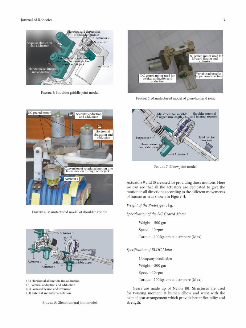
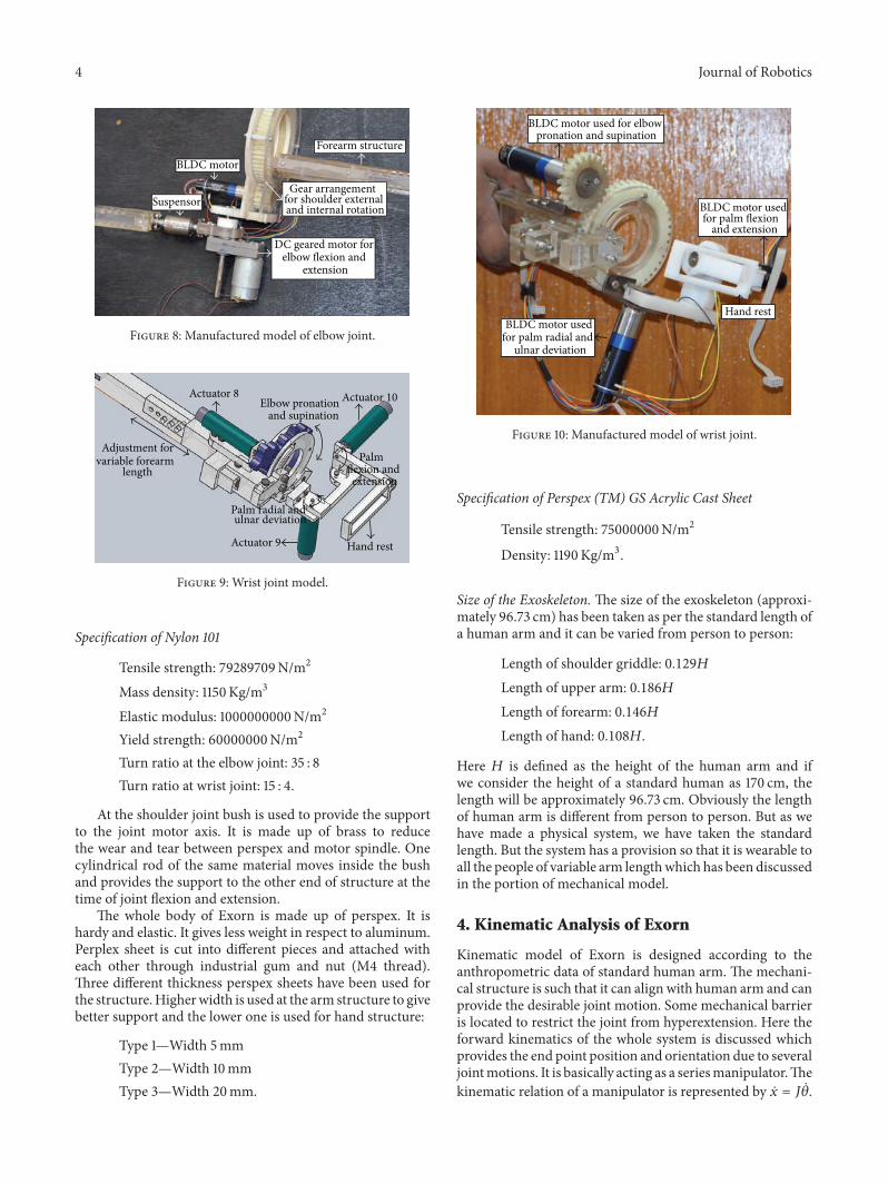
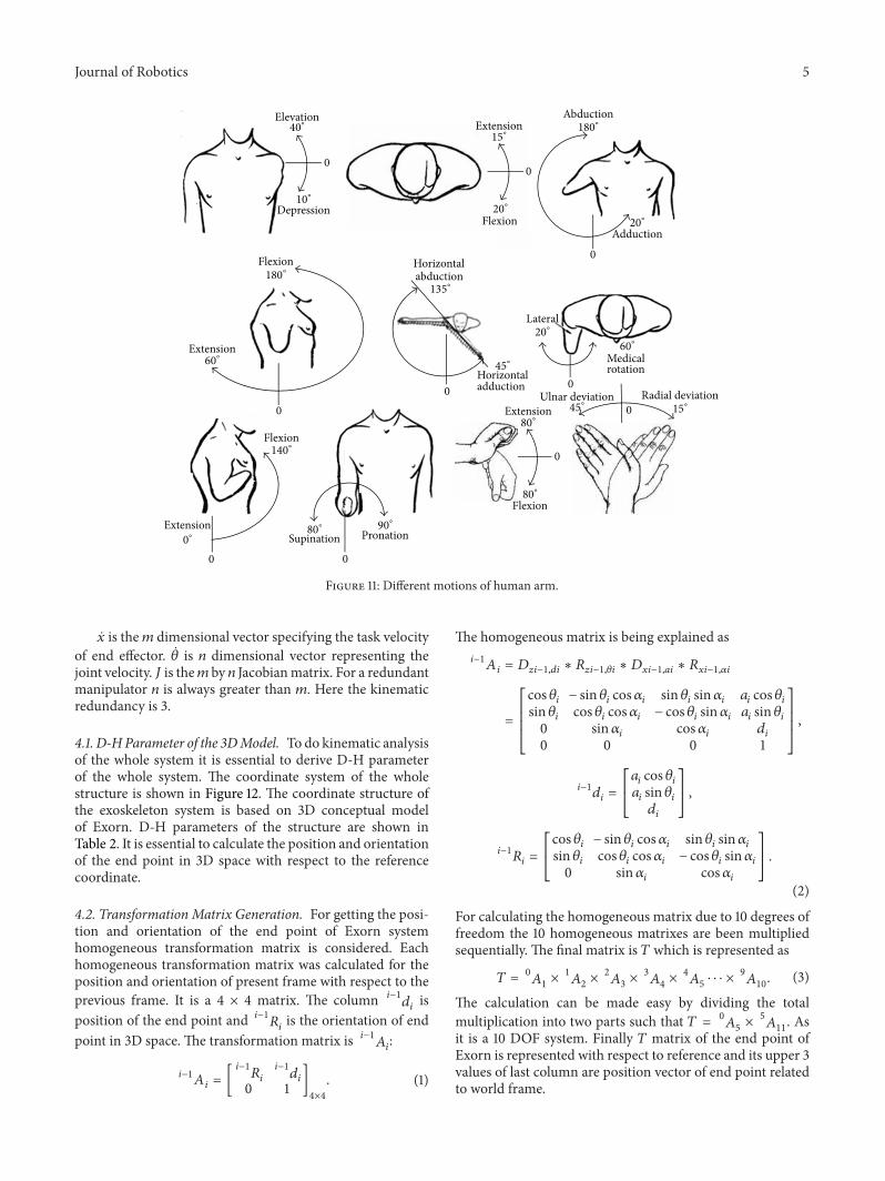
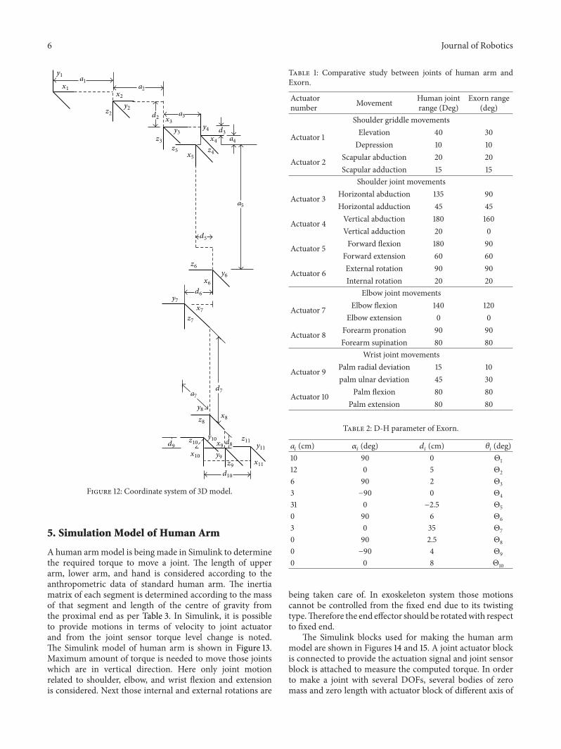
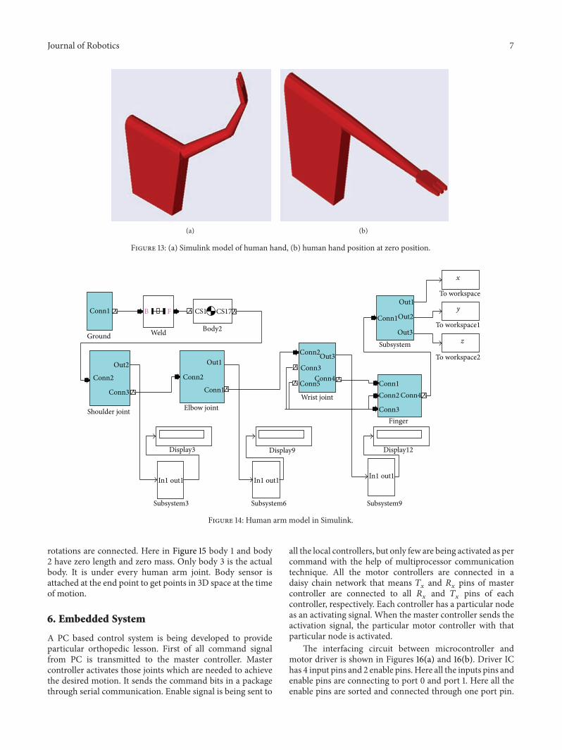
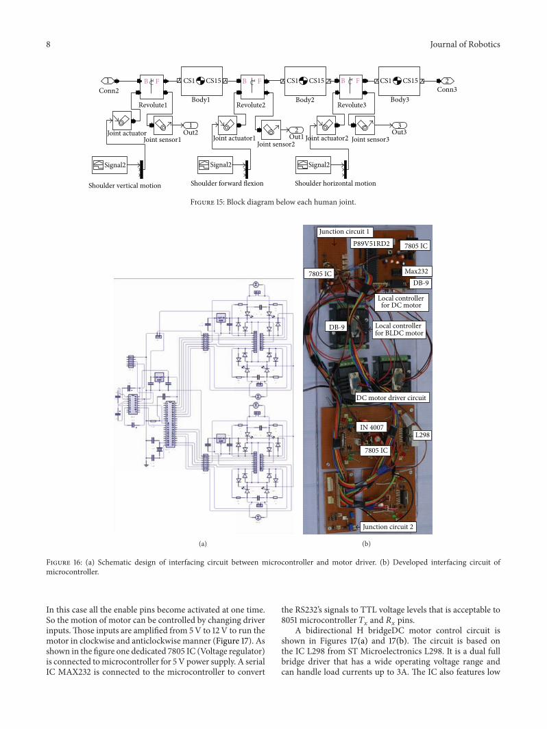
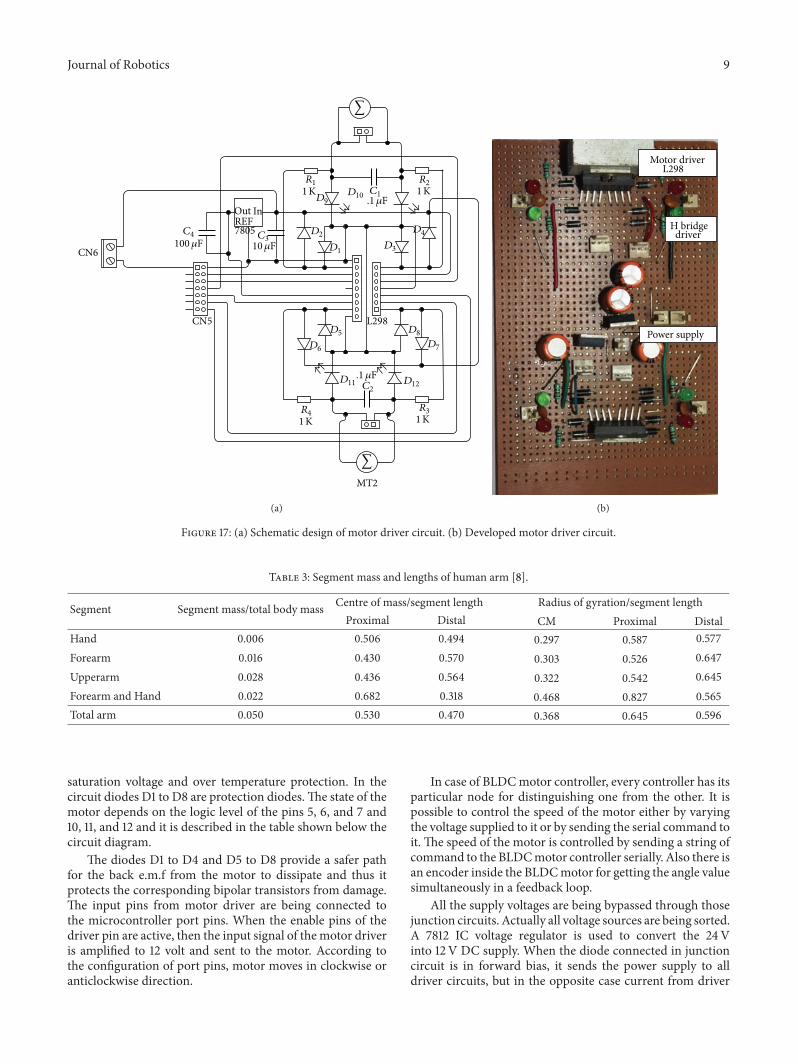
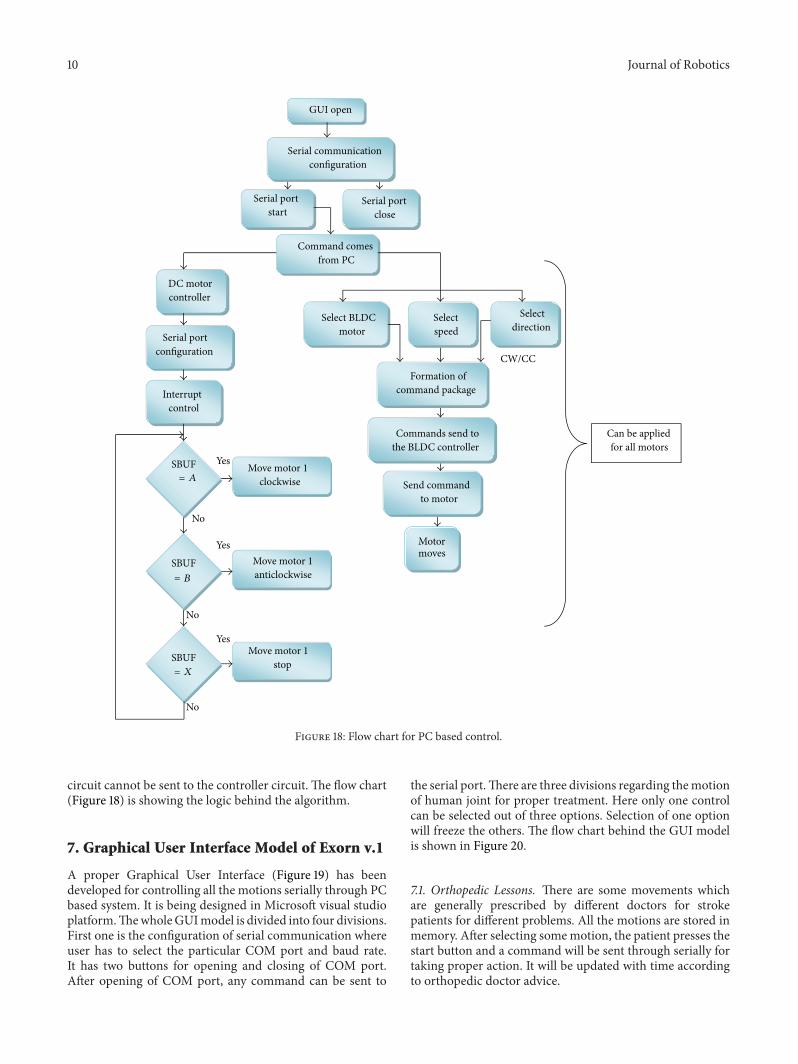
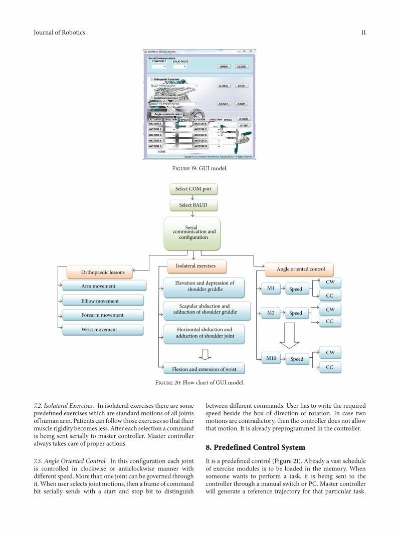
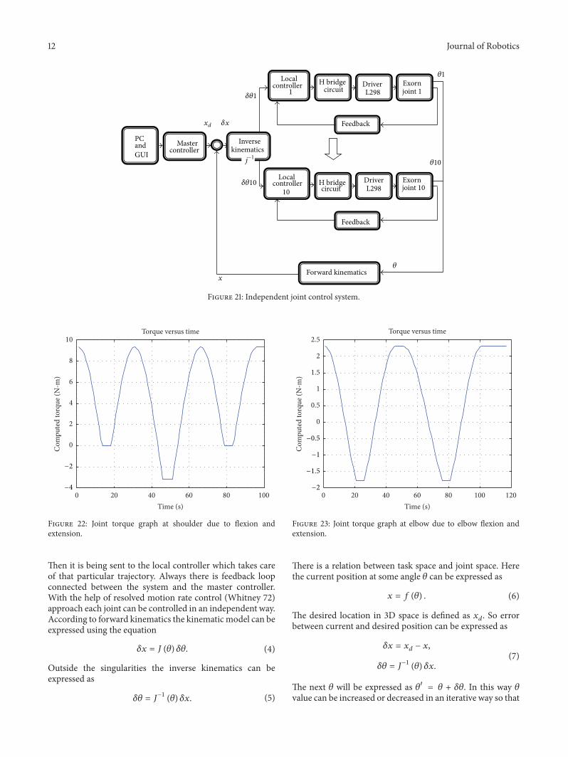
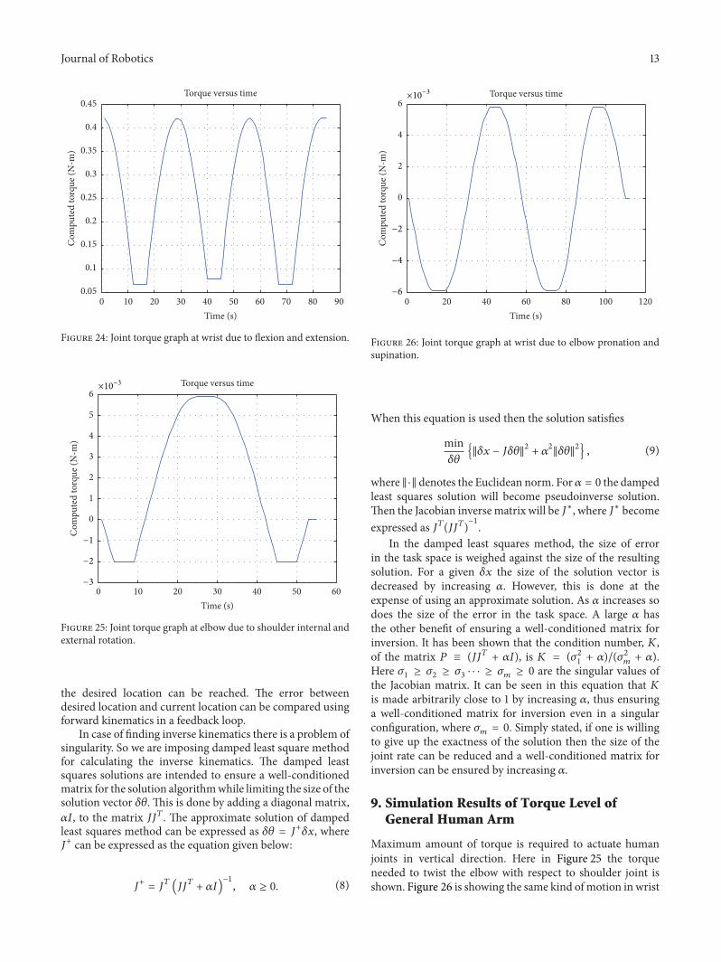
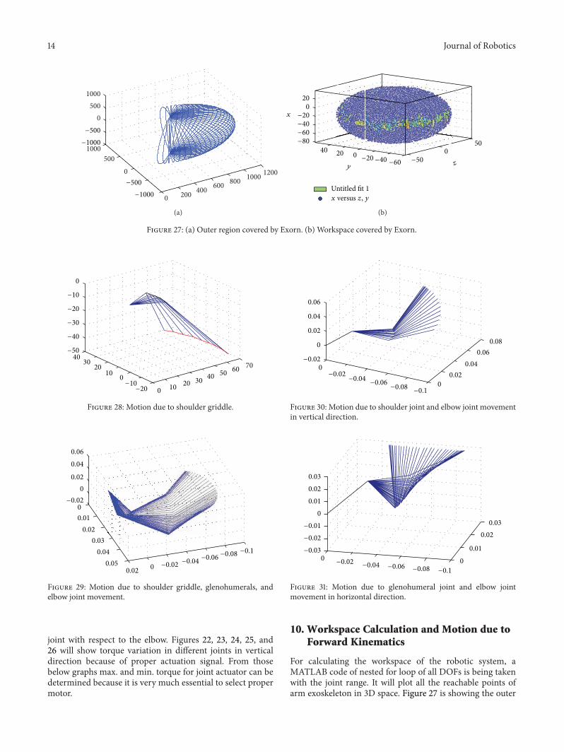

International Journal of
AerospaceEngineeringHindawi Publishing Corporationhttpwwwhindawicom Volume 2014
RoboticsJournal of
Hindawi Publishing Corporationhttpwwwhindawicom Volume 2014
Hindawi Publishing Corporationhttpwwwhindawicom Volume 2014
Active and Passive Electronic Components
Control Scienceand Engineering
Journal of
Hindawi Publishing Corporationhttpwwwhindawicom Volume 2014
International Journal of
RotatingMachinery
Hindawi Publishing Corporationhttpwwwhindawicom Volume 2014
Hindawi Publishing Corporation httpwwwhindawicom
Journal ofEngineeringVolume 2014
Submit your manuscripts athttpwwwhindawicom
VLSI Design
Hindawi Publishing Corporationhttpwwwhindawicom Volume 2014
Hindawi Publishing Corporationhttpwwwhindawicom Volume 2014
Shock and Vibration
Hindawi Publishing Corporationhttpwwwhindawicom Volume 2014
Civil EngineeringAdvances in
Acoustics and VibrationAdvances in
Hindawi Publishing Corporationhttpwwwhindawicom Volume 2014
Hindawi Publishing Corporationhttpwwwhindawicom Volume 2014
Electrical and Computer Engineering
Journal of
Advances inOptoElectronics
Hindawi Publishing Corporation httpwwwhindawicom
Volume 2014
The Scientific World JournalHindawi Publishing Corporation httpwwwhindawicom Volume 2014
SensorsJournal of
Hindawi Publishing Corporationhttpwwwhindawicom Volume 2014
Modelling amp Simulation in EngineeringHindawi Publishing Corporation httpwwwhindawicom Volume 2014
Hindawi Publishing Corporationhttpwwwhindawicom Volume 2014
Chemical EngineeringInternational Journal of Antennas and
Propagation
International Journal of
Hindawi Publishing Corporationhttpwwwhindawicom Volume 2014
Hindawi Publishing Corporationhttpwwwhindawicom Volume 2014
Navigation and Observation
International Journal of
Hindawi Publishing Corporationhttpwwwhindawicom Volume 2014
DistributedSensor Networks
International Journal of