Embed Size (px)
Citation preview

Research ArticleHigh Gain and High Efficient Stacked Antenna Array withIntegrated Horn for 60 GHz Communication Systems
Hamsakutty Vettikalladi, Waleed Tariq Sethi, and Majeed A. Alkanhal
Electrical Engineering Department, King Saud University, Saudi Arabia
Correspondence should be addressed to Hamsakutty Vettikalladi; [email protected]
Received 5 January 2014; Revised 16 February 2014; Accepted 25 February 2014; Published 22 April 2014
Academic Editor: Wenxing Li
Copyright © 2014 Hamsakutty Vettikalladi et al.This is an open access article distributed under the Creative CommonsAttributionLicense, which permits unrestricted use, distribution, and reproduction in anymedium, provided the originalwork is properly cited.
In order to achieve wide bandwidth and high gain, we propose a stacked antenna structure having a microstrip aperture coupledfeeding technique with a mounted Horn integrated on it. With optimized parameters, the single antenna element at a centerfrequency of 60GHz, exhibits a wide impedance bandwidth of about 10.58% (58.9–65.25GHz) with a gain and efficiency of 11.78 dBand 88%, respectively. For improving the gain, we designed a 2 × 2 and 4 × 4 arrays with a corporate feed network. The side lobelevels were minimized and the back radiations were reduced by making use of a reflector at 𝜆/4 distance from the corporate feednetwork.The 2×2 array structure resulted in improved gain of 15.3 dBwith efficiency of 83%, while the 4×4 array structure providedfurther gain improvement of 18.07 dB with 68.3% efficiency.The proposed design is modelled in CSTMicrowave Studio.The resultsare verified using HFSS, which are found to be in good agreement.
1. Introduction
Soon after the development of 60GHz standard that providesa 7GHz license-free bandwidth worldwide, its popularitybecame evident at millimeter waves spectrum due to itsusage in high data-rate wireless communications at gigabitper second [1, 2]. The huge amount of bandwidth availabilityattracted the researchers for its use in many terrestrial andspace applications. In thismodern era of consumer electronicgadgets, even telephony and cable operated devices in officesand homes are trending towards wireless technology. Thedemand for higher data rate of thesemultimedia technologiescan be resolved with 60GHz standard as being a viablecandidate.
In any radio communication or wireless systems, antennaplays a vital part [3–5]. Since its development, the microstripplanar antennas [6] have gained popularity in telecommu-nication and radar applications due to its lightweight andlow profile configurations. Microstrip patch antennas areamong the best candidates for implementing in microwaveand millimeter waves (MMW) frequency and they are goodcandidates for arrays as well. There are several reportsdevoted to the design and explanation of such antennas usingarrays [7–12]. However, the traditional microstrip antennas
have reached their maximum usability as they offer narrowbandwidth (3%) and low gain. Researchers investigated newmethods and came up with coupling techniques to improveimpedance bandwidth. The proposed solution by Pozar [13]is provided with wide bandwidth and high gain as comparedto conventional microstrip antennas. The aperture couplingmethod enabled the patch antennas to be easily integratedinto arrays, with active circuits, to minimize spurious radi-ations from the feed, and to introduce more freedom ofsubstrates selections. Many techniques have been explainedin the literature for improving bandwidth and gain at MMW[14–20].
In this paper, a stacked microstrip antenna utilizingaperture-coupled technique with a mounted Horn on FR-4substrate is presented, at a center frequency of 60GHz. Byemploying this technique, a wide impedance bandwidth ofabout 10.58% (58.9–65.25GHz) is achieved with high gainand efficiency. The gain and efficiency of the single elementantenna are further increased by presenting a corporatefed network of 2 × 2 and 4 × 4 arrays. The 2 × 2 arraystructure resulted in improved gain of 15.3 dB with efficiencyof 83%. While the 4 × 4 array structure provided further gainimprovement of 18.07 dB with 68.3% efficiency. This paper
Hindawi Publishing CorporationInternational Journal of Antennas and PropagationVolume 2014, Article ID 418056, 8 pageshttp://dx.doi.org/10.1155/2014/418056
2 International Journal of Antennas and Propagation
Layer 1 Feed, RT 5880 substrate, and ground with slot
RT 5880 substrate, and patch
FR4 and mounted Horn
Rogers substrate 0.127 mm
Feed line
Slot
Stub
Ground plane
Rogers substrate 0.381 mm
Patch
FR4 substrate Cut in FR4
Mounted Horn
Layer 1
Layer 2 Layer 2
Layer 3
Layer 3
Rohacell foam around the
L 3
Rohacell foam
L g
Wg
Lh
Wh
Ws
L fr
Wp
L PLs
Wf
Wf
r
Horn t = 2mm
t2
t3
t1
with t3 = 1.6mm
Cut inFR4
L ggg
WW
WfWW rff
L 3L 3
Rohacell foamWWgWW
ggg
L frff
Figure 1: Exploded view of proposed multilayer ACMPA with mounted Horn.
is an extended work of our previous results [21], which hadlimited bandwidth. Comparing with previous results [21], theproposed single element antenna’s simulation results showimprovement in terms of bandwidth and gain at millimeterwaves (MMW).
2. Design of Antenna Element
The geometry of the single antenna element is shown inFigure 1. The design is a combination of aperture coupledmicrostrip antenna (ACMPA) and a Horn antenna mountedon FR4 substrate, where the waveguide part of the hornis integrated into FR4 substrate. The model was designedand optimized using RF simulation software CSTMicrowaveStudio and the results were reconfirmed via HFSS. Theantenna is tuned to operate in a wide band of frequenciesat 60GHz. The multilayer antenna has three substrates withlayers I and II having Rogers Duroid RT-5880 with 𝜖𝑟 = 2.2and tan 𝛿 = 0.003 and thickness 𝑡
1= 0.127mm and 𝑡
2=
0.381mm while the third layer has FR-4 as a substrate with𝜖𝑟 = 4.3 and thickness 𝑡
3= 1.6mm and a mounted Horn.
The addition of FR4 has no other effect, except to providesupport to the mounted Horn on the antenna performance.The ground with thickness (𝑡 = 2 × 0.0175mm) is madeof conducting metal with a rectangular slot perpendicular
to the microstrip feed having dimensions of 𝐿𝑠and 𝑊
𝑠as
given in Table 1. Coupling efficiencies between the aperturein the ground and the patch can be improved as investigatedin [22]. The patch is located on the top of the substrate, atlayer II, and has dimensions of 𝐿
𝑝and𝑊
𝑝as given in Table 1.
The dimensions of substrates and ground are taken as 30 ×30mm2. The 50Ωmicrostrip feed line at the bottom of lowersubstrate has a feed width of 𝑊
𝑓= 0.386mm as calculated
fromAnsoftdesigner [23]. Table 1 shows the optimized valuesfor the proposed antenna.
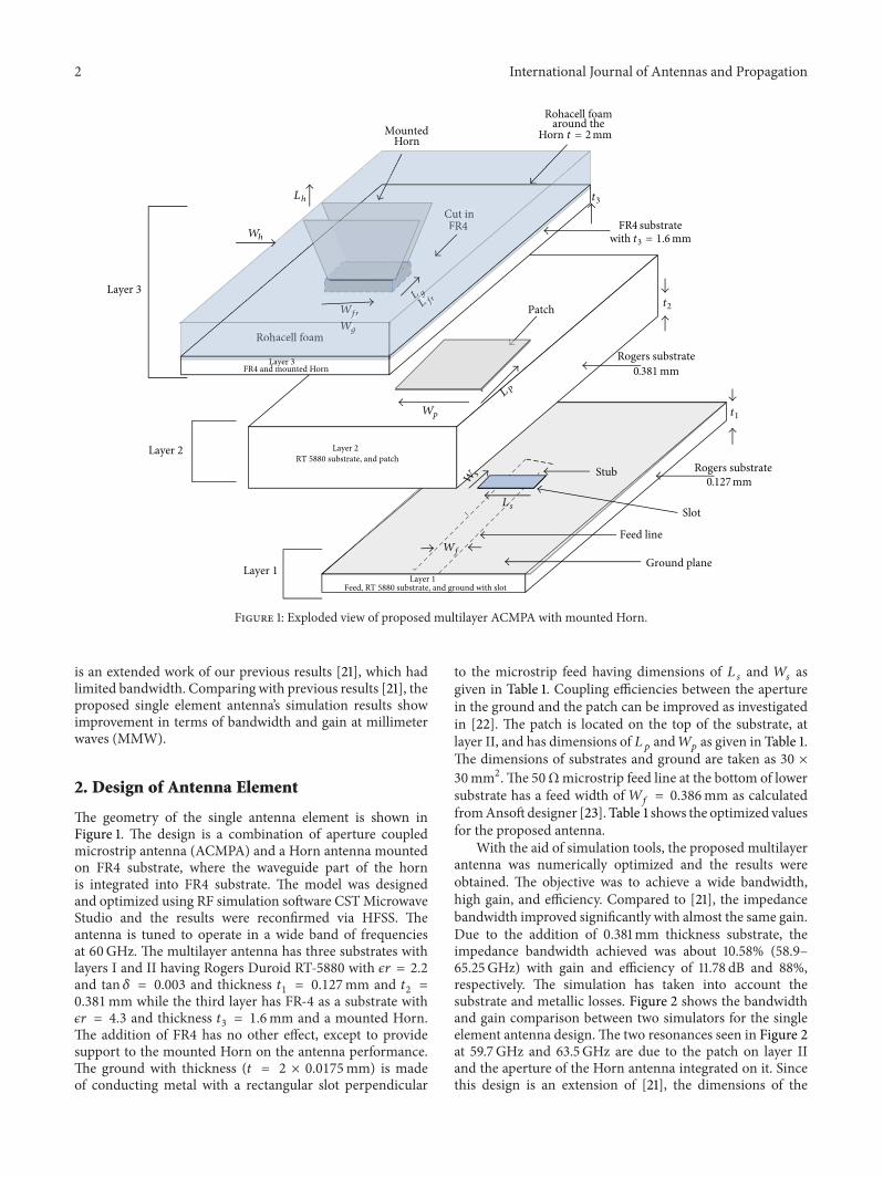
With the aid of simulation tools, the proposed multilayerantenna was numerically optimized and the results wereobtained. The objective was to achieve a wide bandwidth,high gain, and efficiency. Compared to [21], the impedancebandwidth improved significantly with almost the same gain.Due to the addition of 0.381mm thickness substrate, theimpedance bandwidth achieved was about 10.58% (58.9–65.25GHz) with gain and efficiency of 11.78 dB and 88%,respectively. The simulation has taken into account thesubstrate and metallic losses. Figure 2 shows the bandwidthand gain comparison between two simulators for the singleelement antenna design.The two resonances seen in Figure 2at 59.7GHz and 63.5GHz are due to the patch on layer IIand the aperture of the Horn antenna integrated on it. Sincethis design is an extension of [21], the dimensions of the
International Journal of Antennas and Propagation 3
Table 1: Parameters of proposed antenna in mm.
Design Antenna element Dimensions/parameters
Layer I
Microstrip feedFeed width,𝑊
𝑓= 0.386
Thickness, 𝑡 = 0.0175Stub length, 𝐿
𝑓𝑠= 0.45
Substrate
RT Duroid 5880Length, 𝐿 = 30Width,𝑊 = 30𝜖𝑟 = 2.2
tan 𝛿 = 0.003Thickness, 𝑡
1= 0.127
Ground
Thickness, 𝑡 = 0.0175Length 𝐿 = 30Width𝑊 = 30Thickness, 𝑡 = 0.0175
Rectangular slot Slot length, 𝐿𝑠= 1
Slot width,𝑊𝑠= 0.2
Layer IISubstrate
RT Duroid 5880Thickness, 𝑡
2= 0.381
𝜖𝑟 = 2.2
tan 𝛿 = 0.003Length, 𝐿 = 30Width,𝑊 = 30
Patch Length, 𝐿𝑝= 1.2
Width,𝑊𝑝= 1.2
Layer IIISubstrate
FR 4Thickness, 𝑡
3= 1.6
𝜖𝑟 = 4.3
tan 𝛿 = 0.025
Cut in FR-4 Length, 𝐿𝑓𝑟= 3
Width,𝑊𝑓𝑟= 4.25
Horn Horn dimensions
Horn length, 𝐿ℎ= 7.14
Horn width,𝑊ℎ= 7.14
Waveguide length, 𝐿𝑔= 3
Waveguide width,𝑊𝑔= 4.25
Thickness of metal horn, 𝑡 = 2Full structure Total height 4
rectangular waveguide were optimized as given in Table 1.The initial length of the rectangular waveguide was chosento be 𝐿
𝑔= 𝜆0/2, which is a half wavelength at 60GHz. The
rectangular waveguide length has an effect on the reflectioncoefficient, which is minimum when 𝐿
𝑔is around 𝜆
0/2.
Figures 3(a) and 3(b) show the E-plane and H-planeradiation patterns, simulated in CST and HFSS, of theproposed antenna, for the frequencies at 59, 62, and 65GHz,respectively. Thus for the multilayer structure at 62GHz, theE-plane has side lobe of level−5 dB, half-power beamwidth of31∘, and a back radiation of −18.3 dB. The H-plane radiationpattern at 62GHz has a side lobe of −13.2, half-powerbeamwidth of 69.8∘, back radiation of −17 dB, and crosspolarization level of > −30 dB.
57 58 59 60 61 62 63 64 65 66
−50
−40
−30
−20
−10
0
10
(dB)
and
gain
(dB)
Frequency (GHz)
Comparison of return loss and gain [CST versus HFSS]
Gain
CSTHFSS CST
HFSS
S11
S11
Figure 2: Comparison of return loss and gain.
3. Design of Antenna Array
Limited methods exist in analyzing the antenna arrays. Inthe existing methods, arrays factor is the easiest one amongothers [6]. In simplest terms, array theory works on theprinciple that each antenna element is treated as an individualisotropic point source. Energy contributions from each pointsource are derived in the far field expressed as array factor(AF). The method of array factor is based on the theorem oforientation multiplying [6]:
AF (𝑓, 𝜃) =4
∑
𝑛=1
𝑒𝑗𝑛𝑘𝑑 sin 𝜃. (1)
The array factor depends only on the geometry of thearray and the phase between each element. The actualradiator then replaces each point and the far field radiationpattern is determined by pattern multiplying the array factorwith the pattern of the radiator. Mutual coupling is ignoredin the process since the radiators are treated separately; alsotheir influences on each other are not considered. Sincewe areworking on improving the gain of the antenna, therefore, themutual coupling cannot be ignored and the results deducedby array factor must be modified.
3.1. 2 × 2 Array. The next step is to improve the gain bymaking use of 2 × 2 and 4 × 4 arrays. The 3D explodedview of the 2 × 2 arrays structure is shown in Figure 4,where a copper reflector element of distance 𝜆/4 has beenintroduced below layer I to suppress the back radiations ofthe array. An important aspect in designing an array is theoptimal distance between the patches or antenna elements toreduce mutual coupling among them. Mutual coupling has anoteworthy influence on the performance of antenna array.Mutual coupling affects several factors such as inputtingresistance, orientation pattern of array, gain of the array, and

4 International Journal of Antennas and Propagation
−180−150−120 −90 −60 −30 0 30 60 90 120 150 180
Radiation pattern Eco cross at 59 62 65 GHz [CST and HFSS]
Angle (𝜃)
Copolar
CST HFSS59GHz62GHz65GHz
59GHz62GHz65GHz
−40−35
−30
−25
−20
−15
−10
−5
0
5
1015
Gai
n (d
B)
(a)
−40−35
−30
−25
−20
−15
−10
−5
0
5
1015
Gai
n (d
B)
Radiation pattern Hco cross at 59 62 65 GHz [CST and HFSS]
−180 −150 −120 −90 −60 −30 0 30 60 90 120 150 180Angle (𝜃)
CST HFSS59GHz62GHz65GHz
59GHz62GHz65GHz
Copolar
Cross polar
(b)
Figure 3: (a) Simulated E-plane radiation pattern at 59, 62, and 65GHz and (b) simulated H-plane radiation pattern at 59, 62, and 65GHz.
Feed lineSlot
Stub
Ground plane
Patches
Mounted Horn
Rohacell foam
Reflector Air gapLayer-1
Layer 2
Layer 3
Rohacell foam around the
Horn t = 2mm
Rogers substrate 0.381 mm
t2
t1Wp
L P
Wg
Wfr
L g
L fr
Cut in FR4
FR4 substrate with t3
t3
= 1.6mm
Ls
Wf
Ws
Rogers substrate 0.127 mm
Lh
Wh
Layer 1 Feed, RT 5880 substrate, and ground with slot
Layer 1 Feed, RT 5880 substrate, and ground with slot
RT 5880 substrate and patch Layer 2
FR4 and mounted HornLayer 3
𝜆/4
WffWW rff
LLL g
Cut in FR4
LLL ggg
L frff
Rohacell foam WgWW
Layer 3L 3Layer 3
Figure 4: Exploded view of 2 × 2 multilayer array with 𝜆/4 reflector.
International Journal of Antennas and Propagation 5
its polarization [24–27]. In our proposed array design, center-to-center distances between patches were optimized from0.5𝜆 to 1𝜆 that gave minimum coupling and maximum gain.The element spacing was selected to be 0.82𝜆
𝑜in the 𝑥-𝑦
direction for both 2 × 2 and 4 × 4 arrays.A corporate feed network connected to a 50Ω line was
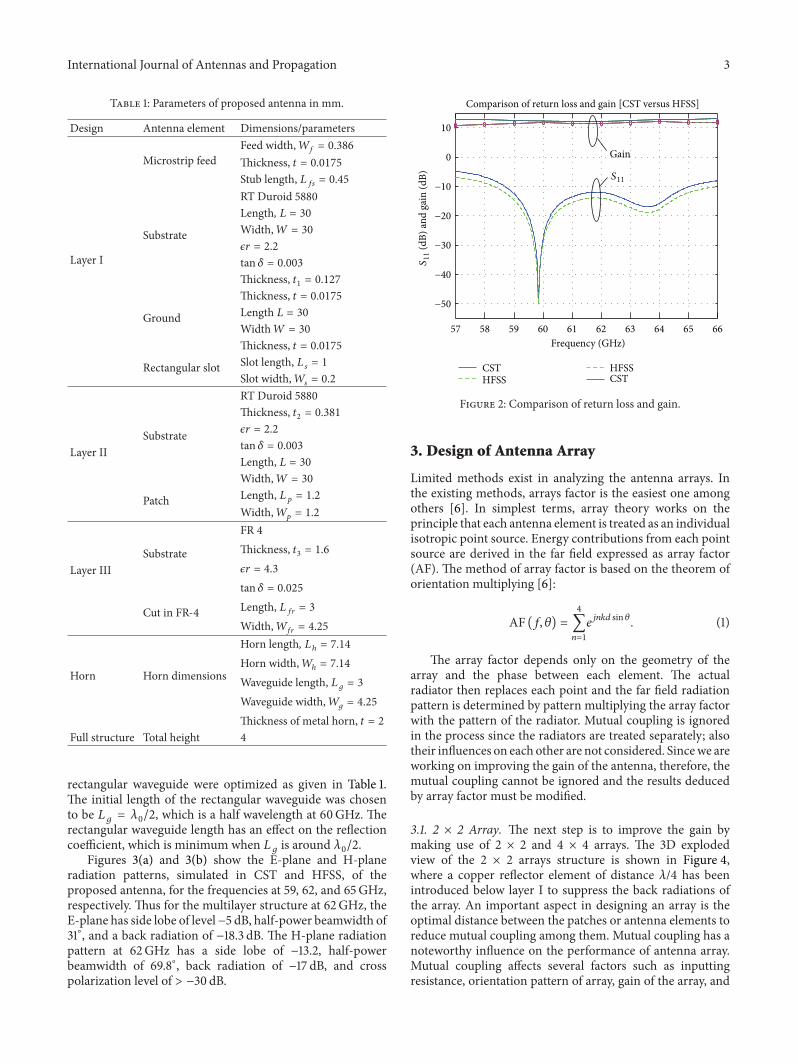
used as power division between antenna elements. Corporatefeed networks are in general very versatile as they offer powersplits of 2𝑛 (i.e., 𝑛 = 2, 4, 8, 16, 32, etc.) and control tothe designer in terms of amplitude and phase selection ofindividual feed element and its power division among thetransmission lines. It is ideal for scanning phased arrays,shaped-beam arrays, and multibeam arrays [6]. The lengthand width of the transmission lines can be varied as perrequirement of power division. The feed network consistsof 50Ω transmission line and 70.7Ω quarter-wavelengthtransformers matched to primary 50Ω feeding line. Thecorporate feed network for 2 × 2 arrays is shown in Figure 5.
Analyzing the top half of feed network shown in Figure 5and because of symmetry, two 50Ω lines coming from eachantenna are connected to two 70.7Ω lines where each of themis a quarter wave transformer. This transforms each line intoa 100Ω line. Nowwe have two 100Ω lines in parallel resultingin 50Ω line. This 50Ω is again connected to quarter wavetransformer resulting in 100Ω line. Similarly, another 100Ωis available from the bottom half of the circuit resulting in afinal 50Ω line connected andmatched to the main 50Ω feed.The lengths and widths of 50Ω and 70.7Ω used in this feednetwork are shown in Table 2.
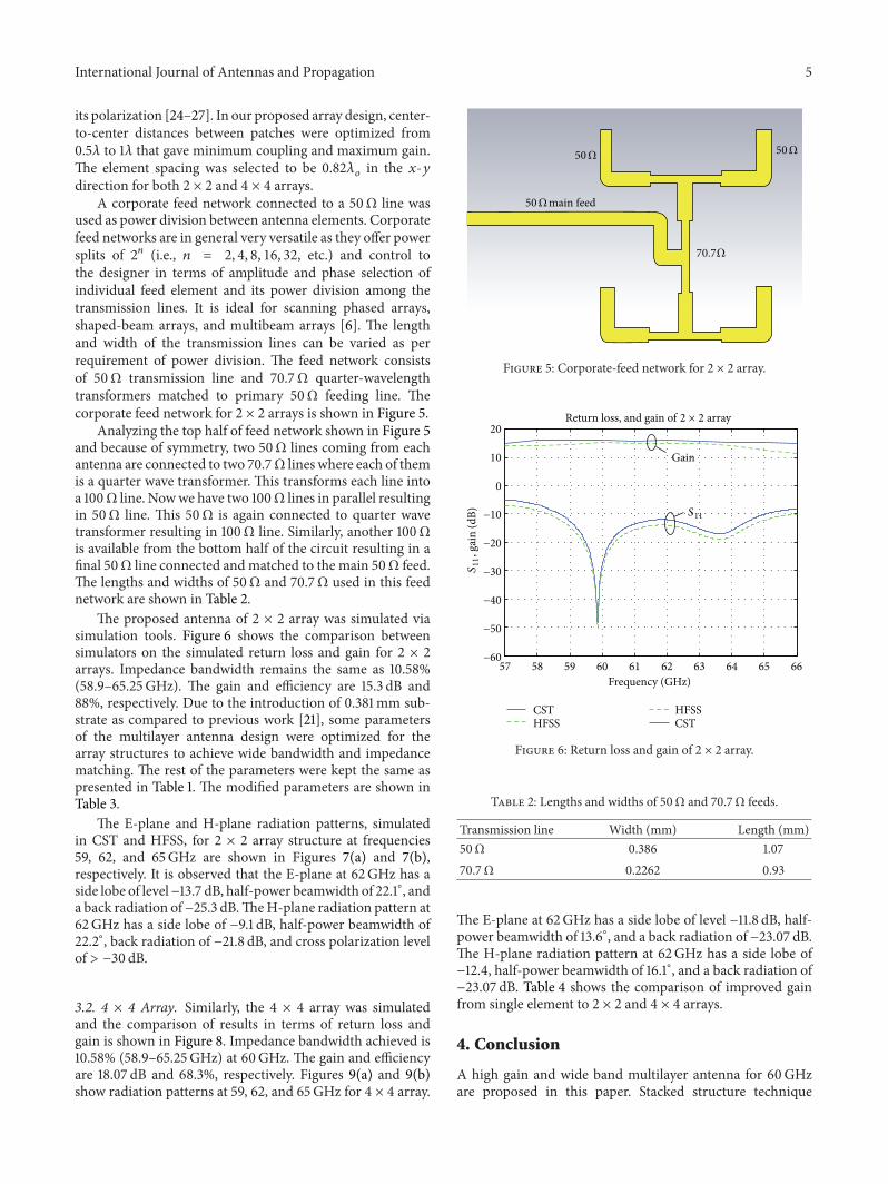
The proposed antenna of 2 × 2 array was simulated viasimulation tools. Figure 6 shows the comparison betweensimulators on the simulated return loss and gain for 2 × 2arrays. Impedance bandwidth remains the same as 10.58%(58.9–65.25GHz). The gain and efficiency are 15.3 dB and88%, respectively. Due to the introduction of 0.381mm sub-strate as compared to previous work [21], some parametersof the multilayer antenna design were optimized for thearray structures to achieve wide bandwidth and impedancematching. The rest of the parameters were kept the same aspresented in Table 1. The modified parameters are shown inTable 3.
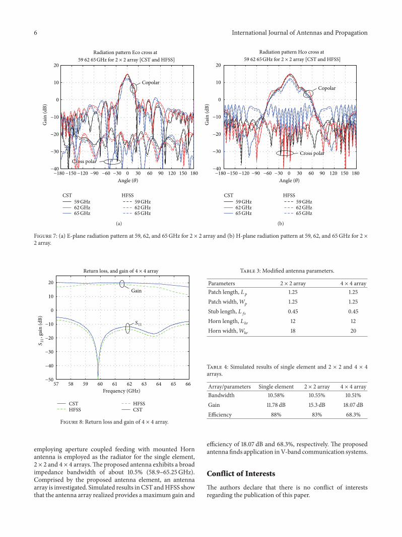
The E-plane and H-plane radiation patterns, simulatedin CST and HFSS, for 2 × 2 array structure at frequencies59, 62, and 65GHz are shown in Figures 7(a) and 7(b),respectively. It is observed that the E-plane at 62GHz has aside lobe of level−13.7 dB, half-power beamwidth of 22.1∘, anda back radiation of −25.3 dB.TheH-plane radiation pattern at62GHz has a side lobe of −9.1 dB, half-power beamwidth of22.2∘, back radiation of −21.8 dB, and cross polarization levelof > −30 dB.
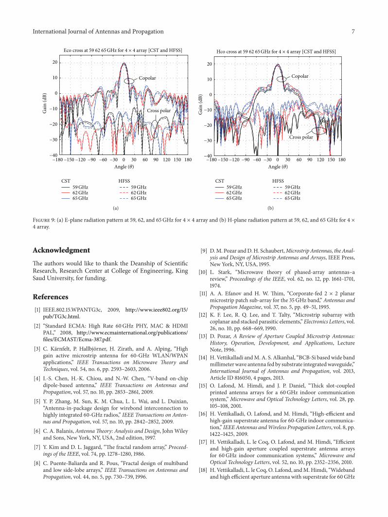
3.2. 4 × 4 Array. Similarly, the 4 × 4 array was simulatedand the comparison of results in terms of return loss andgain is shown in Figure 8. Impedance bandwidth achieved is10.58% (58.9–65.25GHz) at 60GHz. The gain and efficiencyare 18.07 dB and 68.3%, respectively. Figures 9(a) and 9(b)show radiation patterns at 59, 62, and 65GHz for 4 × 4 array.
50 Ω 50 Ω
50 Ωmain feed
70.7 Ω
Figure 5: Corporate-feed network for 2 × 2 array.
57 58 59 60 61 62 63 64 65 66−60
−50
−40
−30
−20
−10
0
10
20
, gai
n (d
B)
Frequency (GHz)
Gain
Return loss, and gain of 2 × 2 array
CSTHFSS CST
HFSS
S11
S11
Figure 6: Return loss and gain of 2 × 2 array.
Table 2: Lengths and widths of 50Ω and 70.7Ω feeds.
Transmission line Width (mm) Length (mm)50Ω 0.386 1.0770.7Ω 0.2262 0.93
The E-plane at 62GHz has a side lobe of level −11.8 dB, half-power beamwidth of 13.6∘, and a back radiation of −23.07 dB.The H-plane radiation pattern at 62GHz has a side lobe of−12.4, half-power beamwidth of 16.1∘, and a back radiation of−23.07 dB. Table 4 shows the comparison of improved gainfrom single element to 2 × 2 and 4 × 4 arrays.
4. Conclusion
A high gain and wide band multilayer antenna for 60GHzare proposed in this paper. Stacked structure technique
6 International Journal of Antennas and Propagation
−40
−30
−20
−10
0
10
20
Gai
n (d
B)Radiation pattern Eco cross at
−180 −150 −120 −90 −60 −30 0 30 60 90 120 150 180Angle (𝜃)
CST HFSS59GHz62GHz65GHz
59GHz62GHz65GHz
59 62 65 GHz for 2 × 2 array [CST and HFSS]
Copolar
Cross polar
(a)
−40
−30
−20
−10
0
10
20
Gai
n (d
B)
−180 −150 −120 −90 −60 −30 0 30 60 90 120 150 180Angle (𝜃)
CST HFSS59GHz62GHz65GHz
59GHz62GHz65GHz
Radiation pattern Hco cross at 59 62 65 GHz for 2 × 2 array [CST and HFSS]
Copolar
Cross polar
(b)
Figure 7: (a) E-plane radiation pattern at 59, 62, and 65GHz for 2 × 2 array and (b) H-plane radiation pattern at 59, 62, and 65GHz for 2 ×2 array.
−50
−40
−30
−20
−10
0
10
20
, gai
n (d
B)
57 58 59 60 61 62 63 64 65 66Frequency (GHz)
CSTHFSS CST
HFSS
Gain
S11
S11
Return loss, and gain of 4 × 4 array
Figure 8: Return loss and gain of 4 × 4 array.
employing aperture coupled feeding with mounted Hornantenna is employed as the radiator for the single element,2 × 2 and 4 × 4 arrays.The proposed antenna exhibits a broadimpedance bandwidth of about 10.5% (58.9–65.25GHz).Comprised by the proposed antenna element, an antennaarray is investigated. Simulated results inCST andHFSS showthat the antenna array realized provides amaximum gain and
Table 3: Modified antenna parameters.
Parameters 2 × 2 array 4 × 4 arrayPatch length, 𝐿
𝑝1.25 1.25
Patch width,𝑊𝑝
1.25 1.25Stub length, 𝐿
𝑓𝑠0.45 0.45
Horn length, 𝐿ℎ𝑟
12 12Horn width,𝑊
ℎ𝑟18 20
Table 4: Simulated results of single element and 2 × 2 and 4 × 4arrays.
Array/parameters Single element 2 × 2 array 4 × 4 arrayBandwidth 10.58% 10.55% 10.51%Gain 11.78 dB 15.3 dB 18.07 dBEfficiency 88% 83% 68.3%
efficiency of 18.07 dB and 68.3%, respectively. The proposedantenna finds application inV-band communication systems.
Conflict of Interests
The authors declare that there is no conflict of interestsregarding the publication of this paper.
International Journal of Antennas and Propagation 7
Eco cross at 59 62 65 GHz for 4 × 4 array [CST and HFSS]
−40
−30
−20
−10
0
10
20
Gai
n (d
B)
−180 −150 −120 −90 −60 −30 0 30 60 90 120 150 180Angle (𝜃)
CST HFSS59GHz62GHz65GHz
59GHz62GHz65GHz
Copolar
Cross polar
(a)
Hco cross at 59 62 65 GHz for 4 × 4 array [CST and HFSS]
−40
−30
−20
−10
0
10
20
Gai
n (d
B)
−180 −150 −120 −90 −60 −30 0 30 60 90 120 150 180Angle (𝜃)
CST HFSS59GHz62GHz65GHz
59GHz62GHz65GHz
Copolar
Cross polar
(b)
Figure 9: (a) E-plane radiation pattern at 59, 62, and 65GHz for 4 × 4 array and (b) H-plane radiation pattern at 59, 62, and 65 GHz for 4 ×4 array.
Acknowledgment
The authors would like to thank the Deanship of ScientificResearch, Research Center at College of Engineering, KingSaud University, for funding.
References
[1] IEEE.802.15.WPANTG3c, 2009, http://www.ieee802.org/15/pub/TG3c.html.
[2] “Standard ECMA: High Rate 60GHz PHY, MAC & HDMIPAL,” 2008, http://www.ecmainternational.org/publications/files/ECMAST/Ecma-387.pdf.
[3] C. Karnfelt, P. Hallbjorner, H. Zirath, and A. Alping, “Highgain active microstrip antenna for 60-GHz WLAN/WPANapplications,” IEEE Transactions on Microwave Theory andTechniques, vol. 54, no. 6, pp. 2593–2603, 2006.
[4] I.-S. Chen, H.-K. Chiou, and N.-W. Chen, “V-band on-chipdipole-based antenna,” IEEE Transactions on Antennas andPropagation, vol. 57, no. 10, pp. 2853–2861, 2009.
[5] Y. P. Zhang, M. Sun, K. M. Chua, L. L. Wai, and L. Duixian,“Antenna-in-package design for wirebond interconnection tohighly integrated 60-GHz radios,” IEEE Transactions on Anten-nas and Propagation, vol. 57, no. 10, pp. 2842–2852, 2009.
[6] C. A. Balanis, AntennaTheory: Analysis and Design, JohnWileyand Sons, New York, NY, USA, 2nd edition, 1997.
[7] Y. Kim and D. L. Jaggard, “The fractal random array,” Proceed-ings of the IEEE, vol. 74, pp. 1278–1280, 1986.
[8] C. Puente-Baliarda and R. Pous, “Fractal design of multibandand low side-lobe arrays,” IEEE Transactions on Antennas andPropagation, vol. 44, no. 5, pp. 730–739, 1996.
[9] D.M. Pozar andD.H. Schaubert,Microstrip Antennas, the Anal-ysis and Design of Microstrip Antennas and Arrays, IEEE Press,New York, NY, USA, 1995.
[10] L. Stark, “Microwave theory of phased-array antennas–areview,” Proceedings of the IEEE, vol. 62, no. 12, pp. 1661–1701,1974.
[11] A. A. Efanov and H. W. Thim, “Corporate-fed 2 × 2 planarmicrostrip patch sub-array for the 35GHz band,” Antennas andPropagation Magazine, vol. 37, no. 5, pp. 49–51, 1995.
[12] K. F. Lee, R. Q. Lee, and T. Talty, “Microstrip subarray withcoplanar and stacked parasitic elements,”Electronics Letters, vol.26, no. 10, pp. 668–669, 1990.
[13] D. Pozar, A Review of Aperture Coupled Microstrip Antennas:History, Operation, Development, and Applications, LectureNote, 1996.
[14] H. Vettikalladi andM. A. S. Alkanhal, “BCB-Si based wide bandmillimeterwave antenna fed by substrate integratedwaveguide,”International Journal of Antennas and Propagation, vol. 2013,Article ID 816050, 4 pages, 2013.
[15] O. Lafond, M. Himdi, and J. P. Daniel, “Thick slot-coupledprinted antenna arrays for a 60GHz indoor communicationsystem,” Microwave and Optical Technology Letters, vol. 28, pp.105–108, 2001.
[16] H. Vettikalladi, O. Lafond, and M. Himdi, “High-efficient andhigh-gain superstrate antenna for 60-GHz indoor communica-tion,” IEEEAntennas andWireless Propagation Letters, vol. 8, pp.1422–1425, 2009.
[17] H. Vettikalladi, L. le Coq, O. Lafond, and M. Himdi, “Efficientand high-gain aperture coupled superstrate antenna arraysfor 60GHz indoor communication systems,” Microwave andOptical Technology Letters, vol. 52, no. 10, pp. 2352–2356, 2010.
[18] H. Vettikalladi, L. le Coq, O. Lafond, andM.Himdi, “Widebandand high efficient aperture antenna with superstrate for 60GHz
8 International Journal of Antennas and Propagation
indoor communication systems,” in Proceedings of the IEEEInternational Symposium on Antennas and Propagation andCNC-USNC/URSI Radio Science Meeting—Leading the Wave(AP-S/URSI ’10), Toronto, Canada, July 2010.
[19] H. Vettikalladi, L. le Coq, O. Lafond, and M. Himdi, “Broad-band superstrate aperture antenna for 60GHz applications,” inProceedings of the 13th European Microwave Week (EuMW ’10),pp. 687–690, Paris, France, September 2010.
[20] N. Ashraf, H. Vettikalladi, and M. A. Alkanhal, “Substrateintegrated waveguide antennas/array for 60GHz wireless com-munication systems,” in Proceedings of the IEEE InternationalRF and Microwave Conference (RFM ’13), 2013.
[21] W. T. Sethi, H. Vettikalladi, and M. A. Alkanhal, “Millimeterwave antenna with mounted horn integrated on FR4 for60GHzGbps communication systems,” International Journal ofAntennas and Propagation, vol. 2013, Article ID 834314, 5 pages,2013.
[22] V. Rathi, G. Kumar, and K. P. Ray, “Improved coupling foraperture coupled microstrip antennas,” IEEE Transactions onAntennas and Propagation, vol. 44, no. 8, pp. 1196–1198, 1996.
[23] “Ansoft designer version 4”.[24] R. P. Jedlicka, M. T. Poe, and K. R. Carver, “Measure mutual
coupling between microstrip antennas,” IEEE Transactions onAntennas and Propagation, vol. 29, no. 1, pp. 147–149, 1981.
[25] M. Malkomes, “Mutual coupling between microstrip patchantennas,” Electronics Letters, vol. 18, no. 12, pp. 520–522, 1982.
[26] E. Penard and J. P. Daniel, “Mutual coupling betweenmicrostripantennas,” Electronics Letters, vol. 18, no. 14, pp. 605–607, 1982.
[27] E. H. van Lil and A. R. van de Capelle, “Transmission linemodel for mutual coupling betweenmicrostrip antennas,” IEEETransactions on Antennas and Propagation, vol. 32, no. 8, pp.816–821, 1984.

International Journal of
AerospaceEngineeringHindawi Publishing Corporationhttp://www.hindawi.com Volume 2014
RoboticsJournal of
Hindawi Publishing Corporationhttp://www.hindawi.com Volume 2014
Hindawi Publishing Corporationhttp://www.hindawi.com Volume 2014
Active and Passive Electronic Components
Control Scienceand Engineering
Journal of
Hindawi Publishing Corporationhttp://www.hindawi.com Volume 2014
International Journal of
RotatingMachinery
Hindawi Publishing Corporationhttp://www.hindawi.com Volume 2014
Hindawi Publishing Corporation http://www.hindawi.com
Journal ofEngineeringVolume 2014
Submit your manuscripts athttp://www.hindawi.com
VLSI Design
Hindawi Publishing Corporationhttp://www.hindawi.com Volume 2014
Hindawi Publishing Corporationhttp://www.hindawi.com Volume 2014
Shock and Vibration
Hindawi Publishing Corporationhttp://www.hindawi.com Volume 2014
Civil EngineeringAdvances in
Acoustics and VibrationAdvances in
Hindawi Publishing Corporationhttp://www.hindawi.com Volume 2014
Hindawi Publishing Corporationhttp://www.hindawi.com Volume 2014
Electrical and Computer Engineering
Journal of
Advances inOptoElectronics
Hindawi Publishing Corporation http://www.hindawi.com
Volume 2014
The Scientific World JournalHindawi Publishing Corporation http://www.hindawi.com Volume 2014
SensorsJournal of
Hindawi Publishing Corporationhttp://www.hindawi.com Volume 2014
Modelling & Simulation in EngineeringHindawi Publishing Corporation http://www.hindawi.com Volume 2014
Hindawi Publishing Corporationhttp://www.hindawi.com Volume 2014
Chemical EngineeringInternational Journal of Antennas and
Propagation
International Journal of
Hindawi Publishing Corporationhttp://www.hindawi.com Volume 2014
Hindawi Publishing Corporationhttp://www.hindawi.com Volume 2014
Navigation and Observation
International Journal of
Hindawi Publishing Corporationhttp://www.hindawi.com Volume 2014
DistributedSensor Networks
International Journal of