Embed Size (px)
Citation preview
Research ArticleOn-Orbit Thermal Design and Validation of1 U Standardized CubeSat of STEP Cube Lab
Soo-Jin Kang and Hyun-Ung Oh
Space Technology Synthesis Laboratory, Department of Aerospace Engineering, Chosun University, 375 Seosuk-dong,Dong-gu, Gwangju 501-759, Republic of Korea
Correspondence should be addressed to Hyun-Ung Oh; [email protected]
Received 6 January 2016; Revised 20 April 2016; Accepted 22 May 2016
Academic Editor: Paolo Tortora
Copyright © 2016 S.-J. Kang and H.-U. Oh. This is an open access article distributed under the Creative Commons AttributionLicense, which permits unrestricted use, distribution, and reproduction in any medium, provided the original work is properlycited.
The Cube Laboratory for Space Technology Experimental Projects (STEP Cube Lab) is a cube satellite (CubeSat) classified asa pico-class satellite of 1 U (unit) size. Its main mission objective is to exploit core space technologies researched by domesticuniversities and verify the effectiveness of these technologies through on-orbit tests using the CubeSat. To guarantee a successfulmission under extreme space thermal environments, proper thermal design is important. This paper describes the developmentprocess undertaken in the thermal design of the STEP Cube Lab, based on a passive approach, and its validation test. The systemfunctionality and thermal design were verified through thermal vacuum and thermal balance tests under space simulated thermalvacuum environment condition. Finally, the orbital temperature of each component was predicted using a highly reliable correlatedthermal mathematical model of the CubeSat obtained from the thermal balance test.
1. Introduction
CubeSat is a cube shaped pico-class satellite with a volume of1000 cm3 and amass of 1.33 kg or less for a standard unit of 1 U.A team of researchers at Stanford University and CaliforniaInstitute of Technology initiated a CubeSat program in 1999to provide a hands-on experience for practical process ofsatellite development to students and engineers [1]. Due tothe considerably lower development costs and shorter devel-opment times than typical commercial satellites, CubeSatprovides an attractive solution for on-orbit verification ofchallenging space missions and technologies [2–4].
STEP Cube Lab is the first 1 U CubeSat developed at theSpace Technology Synthesis Laboratory (STSL) of ChosunUniversity in South Korea. Its main mission objective is toexploit core space technologies researched in domestic uni-versities and verify these technologies through on-orbit oper-ation of the CubeSat. For a successful mission of the STEPCube Lab, its design must be validated with considerationof all environmental conditions spanning from launch to in-orbit operation. The satellite must be able to operate in harsh
space thermal vacuum environment within its allowable tem-perature range. To guarantee the survivability and function-ality of the satellite during its on-orbit mission lifetime underextreme space thermal environment conditions, proper ther-mal design is important for maintaining all on-board equip-ment within their acceptable operating temperature ranges.For passive thermal control, in general, multilayer insulation(MLI) is generally used to shield the spacecraft from incidentenvironmental heat fluxes, while the heat dissipated bythe on-board equipment is rejected into space via specificradiator surfaces coated with selective thermal coatingsor second-surface mirrors. Excessive cooling through theradiator during nonoperating conditions of the equipmentis compensated by a heater. In particular, passive thermaldesign is suitable for thermal control of CubeSats consideringtheir restrictions in power, mass, and volume due to theextremely small accommodation space of CubeSat [5]. Yoo etal. [6] reported the thermal analysis results of a 3U CubeSatof TRIO-CINEMA that used a spin-stabilized attitude con-trol method, having the advantage of thermal stabilizationthrough continuous variation of the incidence angle between
Hindawi Publishing CorporationInternational Journal of Aerospace EngineeringVolume 2016, Article ID 4213189, 17 pageshttp://dx.doi.org/10.1155/2016/4213189

2 International Journal of Aerospace Engineering
the satellite and incident solar flux. Ley at al. [7] reported thethermal design of a COMPASS-1 1 U CubeSat. This thermaldesign also employed a passive approach through use ofblack paint as a surface treatment [8]. Corpino et al. [9]developed a thermal analysis code to solve the thermal energybalance of a nanosatellite in low earth orbit (LEO) througha finite difference numerical approach. Escobar et al. [10]proposed a technique for the automatic design of a CubeSatthermal control system using a genetic algorithm that couldbe utilized for material layout of passive thermal control.
This paper describes the development process applied tothe thermal design of the STEP Cube Lab thermal controlsubsystem, and its subsequent validation through a thermalvacuum test. The following sections include (1) an overviewof the STEP Cube Lab mission including the mechanicalconfiguration and features of the main mission payloads; (2)a thermal design description based on the passive approach,including thermal design drivers, requirements, thermalhardware accommodation, and thermal analysis; (3) a ther-mal vacuum test approach using an indirect heating plate tosimulate orbital temperature conditions and the correspond-ing test results, including the thermal model correlation withthe thermal balance test results; and (4) estimation of thethermal behavior of each component using a reliable corre-lated thermal mathematical model.This paper concludes thatthe thermal design and its validation ensure stable operationof the STEP Cube Lab system within allowable operatingtemperature ranges, as intended by the mission.
2. Overview of the STEP Cube Lab
2.1. Mission Objectives and System Descriptions. The STEPCube Lab has been developed within the frame-work of auniversity program pursing educational but also scientificand technological purposes. The primary objective of itsmissions is to perform on-orbit verification of space-relatedresearch outputs developed at domestic universities. It wasoriginally developed for theoretical research without verifi-cation tests for use in space. In this mission, five payloadsincluding a variable emittance radiator (VER) [11] and aphase change material (PCM) [12, 13] for verifying thermalcontrol equipment, a solar energy collection (SEC) systemusing a commercial Fresnel lens [14] for verifying effectivepower generation, a MEMS-based solid propellant thruster[15] for verifying the MEMS manufacturing process, anda nonexplosive hold-down and release mechanism (HRM)triggered by fuse wire heating [16] are verified through an on-orbit test. A additional goals include on-orbit demonstrationof material competence, such as that of the commercialFresnel lens made of poly-methyl methacrylate (PMMA) andthat of the MEMS thruster control board developed usingcommercial off-the-shelf components.
The STEP Cube Lab is operated using a circular sun-synchronous orbit with an altitude of 600 km and an incli-nation angle of 97.78∘. The expected mission lifetime is 1 year.Taking into account the previously stated mission objectiveand themechanical constraints due to the limited volume andmass of 1 U CubeSat, a passive attitude stabilization method[17] using a permanent magnet combined with hysteresis
Table 1: System specification of STEP Cube Lab.
Item SpecificationsUnit 1 UOrbit Sun synchronous orbitAltitude 600 kmInclination angle 97.78∘
Period 5801.23 secLife time 1 year
Payloads
Variable emittance radiator (VER)Phase change material (PCM)Solar energy collection system (SEC)MEMS-based solid propellant thrusterHold-down and release mechanism (HRM)
Mass 0.92 kgThermal control PassiveAttitude control Permanent magnet attitude stabilizationCommunication UHF (437.485MHz)
dampers was selected due to its simplicity, small mass, andvolume of attitude control system. The permanent magnetis used to generate control torques aligning the body axis ofthe satellite with the Earth’s magnetic field lines. Hysteresisdampers are used to dampen oscillations of the satellite,induced immediately after being released from the launcher.As a result, the satellite performs two rotations per orbit.Thisprovides the advantage of thermal stabilization of the satellite,because the incidence angle between the satellite and the solarflux vector is continuously changing. Table 1 lists the basicspecifications of the STEP Cube Lab.
2.2. Satellite’s Configuration and Mission Payloads. Figure 1shows the mechanical configuration of the STEP Cube Lab;its design was based on a 1U standardized CubeSat. Thetotal mass of the satellite is 0.92 kg, with a margin of 0.41 kgwith respect to the requirement of 1.33 kg for 1 U CubeSats.The total generated power is 2.2W, with a margin of 0.5Wwith respect to the required power of 1.7W. All structuralelements were manufactured by aluminium alloy (Al-6061)with a black anodizing treatment. Four of six external panelswere covered with gallium arsenide triple junction solarcells on the +𝑋, −𝑋, +𝑌, and −𝑌 panels. To maximize theaccommodation efficiency, a commercial UHF half-duplexantenna [18] combinedwith buck converter forUHF commu-nication mode transition (437.485MHz) was considered. Tosecure the structural safety of the deployable antenna underlaunch conditions, the antenna was fixed by a nylon wireon the upper +𝑍 panel of the interface board, having thefunction of electrical interfacemanagement, andwas releasedby a fuse wire heating trigger. A Global Positioning System(GPS) antenna was also installed on the +𝑍 panel for thesatellite time synchronization and position data acquisitionafter MEMS thruster activation. Electronic boards of On-board Computer (OBC), Electrical Power System (EPS)with a Li-ion battery, communication, GPS, and payloadplate stacked together were fixed to the upper and lower

International Journal of Aerospace Engineering 3
Z
Y
X
VER(variable emittance
radiator)
HRM(hold-down and
release mechanism)
Fixed emittance radiator
GPS antenna
UHF antenna
Interface board
(a)
Z
Y
X
MEMS thruster
SEC(solar energy collection
MEMS bracket
Solar cellsystem on +X and −X)
(Delrin® )
(b)
Z
Y
X
Deployment status switch
PCM (phase change
material)
GPS board Communication board
OBC board
EPS board
Payload board
HRM(hold-down and
release mechanism)
(c)
Figure 1: Mechanical configuration of the STEP Cube Lab ((a) and (b) external configuration, (c) internal configuration).
CubeSat structures by using Printed Circuit Board (PCB)supporters. The payload plate was manufactured using Al-6061 for mounting the mission payloads of the PCM and theHRM assembly with a deploy status switch.
Figures 2, 3, 4, 5, and 6 show the developed on-boardpayloads to be verified in this mission. The location of eachpayload is also shown in Figure 1. The VER and the PCMselected for the purpose of on-orbit verification of thermalcontrol device are shown in Figures 2 and 3. The VER shownin Figure 2(a) was installed on the +𝑍 panel and is a smartradiation device based on the metal insulator transition ofa (La,Sr)MnO
3thin film, which significantly varies in its
emittance value according to the temperature variation asshown in Figure 2(b). It may be effective in minimizingadditional heater power consumption under cold conditions,unlike conventional radiators with fixed emittance values.The effectiveness of theVERwill be verified by comparing theon-orbit temperature profile with that of the fixed emittanceradiator (FER) coated with Kapton tape installed near theVER shown in Figure 1.
The PCM shown in Figure 3(a) was positioned on thepayload plate inside of the satellite and its location is shown
in Figure 1(c). Figure 3(b) shows the verification test resultsof PCM. The PCM is a heat storage device that can store andrelease latent heat energy through a solid-liquid phase changeat the designated temperature. Therefore, it is capable ofachieving efficient heatmanagement with a lessmass than theconventional heat sink mass. A paraffin n-pentadecane of 2 gwith a phase change temperature of 10∘Cwas selected as func-tional fluid for the PCM, considering the temperature rangeof the satellite predicted using on-orbit thermal analysis. Totallatent heat of the PCM developed in this study is 326 J.
TheHRMshown in Figure 4was positioned in themiddleof the payload plate. Figure 4(a) shows images capturedby the high-speed camera in a successful release of themechanism at the lower limit of the qualification temperature(−20∘C) obtained during the qualification test at the mecha-nism level [16]. Figure 4(b) shows the deployed and stowedconfigurations of the mechanism module on the payloadplate, composed of the HRM and deployment status switchused to evaluate successful on-orbit operation.The activationprinciple of the mechanism was based on the cutting of anylon cable triggered by fuse wire heating generally usedin cube satellite applications. A high axial load capability

4 International Journal of Aerospace Engineering
(a)
120
Measurement (Ω/2𝜋 = 0.075)Measurement (Ω/2𝜋 = 0.03)
Ref. data (Japan)Fitted curve (ref.)
0 8040−80 −40
Temperature (∘C)
0.2
0.4
0.6
0.8
Tota
l hem
isphe
rical
emitt
ance
,𝜀
(b)
Figure 2: Variable emissivity radiator (VEM).
of the mechanism was achieved by clamping the constraintbolt to the separation nut, which is constrained by the nyloncable winding.This offered several advantages, such as a largeholding capacity and negligible induced shock compared toconventional fuse wire release mechanisms used in CubeSatapplications. Successful release of the mechanism on-orbit isevaluated by a deployment status switch.
To enhance the power generation performance of Cube-Sats given their mass and volume limitations, an SEC systemusing a Fresnel lens was employed and its performancewas verified by on-orbit testing. Figure 5(a) illustrates thebasic operating principle of the SEC system. The systemenhances power generation performance by concentratingand illuminating solar energy onto the solar panels using acommercial Fresnel lens installed at the edge of a solar panelas shown in Figure 1(b) even in the worst case scenario ofthe sun’s incidence angle (𝛽 = 0). Figure 5(b) shows thetest results of the SEC system using a Fresnel lens and solar
(a)
PCMChamber temperature
400 600 800 1000200Time (min)
Tem
pera
ture
(∘C)
−40
−20
0
20
40
60
(b)
Figure 3: Phase change material (PCM).
simulator indicating that the SEC system using a Fresnel lensgenerates energy much more efficiently than without the lenssystem [14]. The Fresnel lens was installed at the edge ofthe solar panels in the +𝑋 and −𝑋 directions, as shown inFigure 1(b), to verify the proposed solar energy collectionsystem by comparing the power generation performancebetween the solar panels with and without the Fresnel lens.
A MEMS-based solid propellant thruster array inFigure 6 was installed in the −𝑍 direction of the satellite.The objective of on-orbit verification of the MEMS thrusteris to verify the MEMS fabrication process for use in spacerather than its attitude determination capabilities. Long-termreliability of this technology must be established throughexperiments in space in order to achieve the goal of sendinga completely microfabricated and integrated MEMS systeminto space. MEMS technology is very attractive for spaceapplications because of largely reduced size, mass, and power

International Journal of Aerospace Engineering 5
5.247 sec4.779 sec4.645 sec4.312 sec
(a)
Constraint bolt
Deployment status switchPreload
springUnfoldedpreloadsspring
Deployedconstraint bolt
Pushed switch by separated nut
(b)
Figure 4: Nonexplosive hold-down and release mechanism (HRM).
Sun
Solar panel
Fresnel lens
ZYX
Fresnel lens𝛽 = 0∘
𝜃
(a)
0 0.2 0.4 0.6 0.8 1
With Fresnel lensWith multiarray lens
Without lens
Voltage (V)
0
10
20
30
40
50
Curr
ent (
mA
)
(b)
Figure 5: Solar energy collection system using Fresnel lens (SEC).
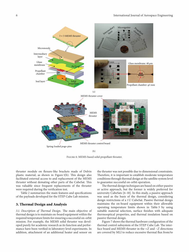
consumption throughminiaturization of its components andsystems. Figure 6(a) shows the cross section of the MEMSsolid thruster developed by Lee et al. [15]. The operationprinciple is as follows: when the solid propellant reachesignition temperature achieved by the microigniter, the glassmembrane is subsequently broken by the high-energy com-bustion gases of the solid propellant.Thrust is then generatedthrough the micronozzle. The microigniter is also used as amicroresistance temperature detector to judge the status ofthruster. Figure 6(b) shows an exploded schematic view oftheMEMS thruster module composed of theMEMS thruster
and control board. To achieve reliable electrical contact andsurvivability, electrode pads design was used in conjunctionwith spring-loaded pogo-pins. As shown in the explodedschematic view of Figure 6(b), the electrical interface onthe thruster was directly connected to the pogo-pins on thethruster control board and fixed by a plastic cover made ofDelrin with space heritage. To ensure successful on-orbitverification of the MEMS thruster array, structural designefforts at the satellite level were performed to minimizethe launch loads transmitted to the thruster under launchenvironments. This was achieved by mounting the MEMS
6 International Journal of Aerospace Engineering
Micronozzle
Intermediary layer
Glass membrane
Propellant chamber
Solid propellant
Seal layer
30 mm
Microigniter
3 × 3 MEMS thruster
Propellant chamber:
30mm Glass membrane:Pt/Ti igniter
Intermediary
layer
Micr
onoz
zle
Propellantchamber
Seal layer
𝜑1mm
40𝜇m
(a)
MEMS thruster
Spring-loaded pogo-pinsMEMS thruster control board
MEMS thruster cover
(b)
Figure 6: MEMS-based solid propellant thruster.
thruster module on flexure-like brackets made of Delrinplastic material, as shown in Figure 1(b). This design alsofacilitated external access to and replacement of the MEMSthruster without demating other parts of the CubeSat. Thiswas valuable since frequent replacements of the thrusterwere required during the verification test.
Table 2 summarizes the main features and specificationsof the payloads developed for the STEP Cube Lab mission.
3. Thermal Design and Analysis
3.1. Description of Thermal Design. The main objective ofthermal design is tomaintain on-board equipment within therequired temperature limits for ensuring a successful on-orbitmission. For example, the MEMS solid thruster was devel-oped purely for academic research as its function and perfor-mance have been verified in laboratory level experiments. Inaddition, attachment of an additional heater and sensor on
the thruster was not possible due to dimensional constraints.Therefore, it is important to establish moderate temperatureconditions through thermal design at the satellite system levelto guarantee successful on-orbit operation.
The thermal design techniques are based on either passiveor active approach, but the former is widely preferred foruniversity CubeSats [6–10]. In this study, a passive approachwas used as the basis of the thermal design, consideringdesign restrictions of a 1 U CubeSat. Passive thermal designmaintains the on-board equipment within their allowableoperating temperature limits shown in Table 3 by usingsuitable material selection, surface finishes with adequatethermooptical properties, and thermal insulation based onpassive thermal design.
Figure 7 shows the thermal hardware configuration of thethermal control subsystem of the STEP Cube Lab. The inter-face board and MEMS thruster in the +𝑍 and −𝑍 directionsare covered by MLI to reduce excessive thermal flux from/to

International Journal of Aerospace Engineering 7
MLI
(a)
MLI
MEMS thruster
MEMS I/F board
(b)
Variable emittance radiator
MLIThermal washer
Fixed emittance radiator
(c)
HeaterHeater
(d)
Figure 7: Accommodation of thermal control hardware.
Table 2: Specification of mission payloads for STEP Cube Lab.
Payload Specification
VER Dimension: 30mm × 30mmEmissivity: 0.28 (at −40∘C), 0.41 (at 0∘C),and 0.54 (at +40∘C)
PCMMelting point: 10∘CTotal latent heat: 326 JFunctional fluid: paraffin n-pentadecane
SEC
Optic: Fresnel lensMaterial: poly methyl methacrylate(PMMA)Transmission efficiency: 92%(at 400–1100 nm)
MEMS thruster Max thrust: 3.62N,Specific impulse: 62.3 sec
HRMAllowable axial force: 3200NRelease time (vacuum): <0.71 s (−35∘C)Max shock level: SRS 65 g
components as shown in Figures 7(a) and 7(b). MLI used inthis program consists of 12 inner layers of 1/4mil aluminizedMyler, innermost and outermost layers of 1mil aluminizedKapton with effective emissivity of 0.8 and solar absorptivityof 0.4. To minimize the external effects on the performanceof variable and fixed emittance radiators for proper verifica-tion on-orbit, the radiators are radiatively and conductivelyinsulated from the satellite using a thermal washer with 2mmthickness ofG10 andMLI, as shown in Figure 7(c). A thin filmheater was attached to the bottom of the PCM as shown inFigure 7(d), if an additional heat source is necessary to createtemperature condition for monitoring a phase change tran-sition region on-orbit. In the thermal design of STEP CubeLab, there is not any heat transport path from the stacked
Table 3: Allowable operating temperature for STEP Cube Labcomponents.
UnitHeat
dissipation[W]
Allowable temperaturerange [∘C]
𝑇min 𝑇max
EPS board 0.10 −40 +85Battery 0.60 −20 +60Interface board 0.03 −40 +85Communication board 0.27 −30 +60OBC board 0.11 −40 +85GPS board 0.27 −40 +85MEMS control board 0.01 −35 +60Solar panels — −100 +100SEC — −70 +80HRM — −35 +50MEMS thruster — −35 +60
electronic boards to the dedicated radiator because thegenerated heats are mainly dissipated by radiation.
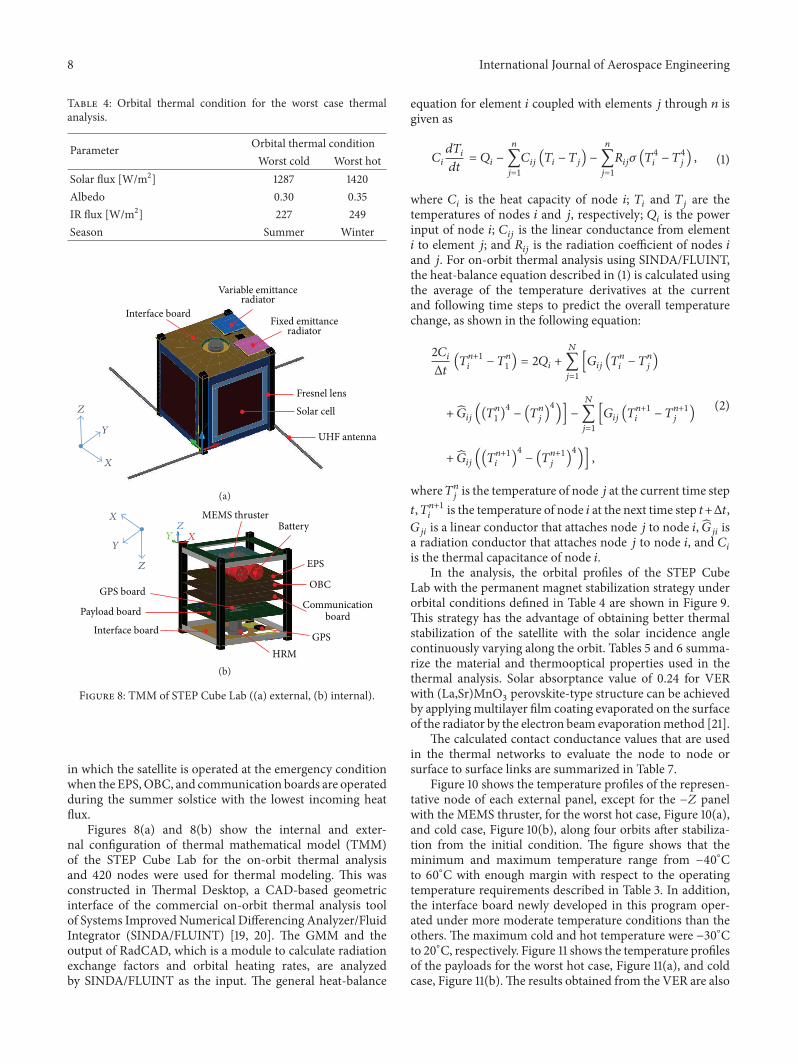
3.2. Thermal Analysis. The objective of the thermal analysisis to confirm that the thermal design meets the temperaturerequirements shown in Table 3 for all equipment during themission phase. Heat dissipation values used for the analysisare also summarized in Table 3. Table 4 lists the orbitalconditions used in the on-orbit thermal analysis for the STEPCube Lab. In the thermal analysis, we defined the worst hotand cold cases in order to consider the critical temperatureconditions of the satellite described in Table 4. The worst hotcondition corresponds to the case in which the satellite withmaximum heat dissipation of the components is operatedduring thewinter solsticewith the highest incoming heat flux.In contrast, the worst cold condition corresponds to the case
8 International Journal of Aerospace Engineering
Table 4: Orbital thermal condition for the worst case thermalanalysis.
Parameter Orbital thermal conditionWorst cold Worst hot
Solar flux [W/m2] 1287 1420Albedo 0.30 0.35IR flux [W/m2] 227 249Season Summer Winter
Z
Y
X
Variable emittanceradiator
Fixed emittanceradiator
Interface board
Fresnel lens
Solar cell
UHF antenna
(a)
BatteryMEMS thruster
EPS
OBC
CommunicationboardPayload board
GPS board
Interface board
HRMGPS
Z
YY
XZ
X
(b)
Figure 8: TMM of STEP Cube Lab ((a) external, (b) internal).
in which the satellite is operated at the emergency conditionwhen the EPS,OBC, and communication boards are operatedduring the summer solstice with the lowest incoming heatflux.
Figures 8(a) and 8(b) show the internal and exter-nal configuration of thermal mathematical model (TMM)of the STEP Cube Lab for the on-orbit thermal analysisand 420 nodes were used for thermal modeling. This wasconstructed in Thermal Desktop, a CAD-based geometricinterface of the commercial on-orbit thermal analysis toolof Systems Improved Numerical Differencing Analyzer/FluidIntegrator (SINDA/FLUINT) [19, 20]. The GMM and theoutput of RadCAD, which is a module to calculate radiationexchange factors and orbital heating rates, are analyzedby SINDA/FLUINT as the input. The general heat-balance
equation for element 𝑖 coupled with elements 𝑗 through 𝑛 isgiven as
𝐶𝑖
𝑑𝑇𝑖
𝑑𝑡= 𝑄𝑖−
𝑛
∑𝑗=1
𝐶𝑖𝑗(𝑇𝑖− 𝑇𝑗) −
𝑛
∑𝑗=1
𝑅𝑖𝑗𝜎 (𝑇4
𝑖− 𝑇4
𝑗) , (1)
where 𝐶𝑖is the heat capacity of node 𝑖; 𝑇
𝑖and 𝑇
𝑗are the
temperatures of nodes 𝑖 and 𝑗, respectively; 𝑄𝑖is the power
input of node 𝑖; 𝐶𝑖𝑗is the linear conductance from element
𝑖 to element 𝑗; and 𝑅𝑖𝑗is the radiation coefficient of nodes 𝑖
and 𝑗. For on-orbit thermal analysis using SINDA/FLUINT,the heat-balance equation described in (1) is calculated usingthe average of the temperature derivatives at the currentand following time steps to predict the overall temperaturechange, as shown in the following equation:
2𝐶𝑖
Δ𝑡(𝑇𝑛+1
𝑖− 𝑇𝑛
1) = 2𝑄
𝑖+
𝑁
∑𝑗=1
[𝐺𝑖𝑗(𝑇𝑛
𝑖− 𝑇𝑛
𝑗)
+ �̂�𝑖𝑗((𝑇𝑛
1)4− (𝑇𝑛
𝑗)4
)] −
𝑁
∑𝑗=1
[𝐺𝑖𝑗(𝑇𝑛+1
𝑖− 𝑇𝑛+1
𝑗)
+ �̂�𝑖𝑗((𝑇𝑛+1
𝑖)4
− (𝑇𝑛+1
𝑗)4
)] ,
(2)
where𝑇𝑛𝑗is the temperature of node 𝑗 at the current time step
𝑡,𝑇𝑛+1𝑖
is the temperature of node 𝑖 at the next time step 𝑡+Δ𝑡,𝐺𝑗𝑖is a linear conductor that attaches node 𝑗 to node 𝑖, �̂�
𝑗𝑖is
a radiation conductor that attaches node 𝑗 to node 𝑖, and 𝐶𝑖
is the thermal capacitance of node 𝑖.In the analysis, the orbital profiles of the STEP Cube
Lab with the permanent magnet stabilization strategy underorbital conditions defined in Table 4 are shown in Figure 9.This strategy has the advantage of obtaining better thermalstabilization of the satellite with the solar incidence anglecontinuously varying along the orbit. Tables 5 and 6 summa-rize the material and thermooptical properties used in thethermal analysis. Solar absorptance value of 0.24 for VERwith (La,Sr)MnO
3perovskite-type structure can be achieved
by applyingmultilayer film coating evaporated on the surfaceof the radiator by the electron beam evaporationmethod [21].
The calculated contact conductance values that are usedin the thermal networks to evaluate the node to node orsurface to surface links are summarized in Table 7.
Figure 10 shows the temperature profiles of the represen-tative node of each external panel, except for the −𝑍 panelwith the MEMS thruster, for the worst hot case, Figure 10(a),and cold case, Figure 10(b), along four orbits after stabiliza-tion from the initial condition. The figure shows that theminimum and maximum temperature range from −40∘Cto 60∘C with enough margin with respect to the operatingtemperature requirements described in Table 3. In addition,the interface board newly developed in this program oper-ated under more moderate temperature conditions than theothers. The maximum cold and hot temperature were −30∘Cto 20∘C, respectively. Figure 11 shows the temperature profilesof the payloads for the worst hot case, Figure 11(a), and coldcase, Figure 11(b).The results obtained from the VER are also

International Journal of Aerospace Engineering 9
(a)
MEMS thruster
Interface board
(b)
Figure 9: Orbit profile of STEP Cube Lab with permanent magnet stabilization strategy ((a) view from the orbit normal direction, (b) viewfrom the sun).
Table 5: Summary of material properties used in the analysis.
Component Material Density [kg/m3] Thermal conductivity[W/m-K] Specific heat [J/kg/K]
Structure Al6061-T6 2700 171 920PCB FR4 1900 0.1 1200Solar cell ITO-GaAs 5316 46.05 350Battery Lithium-ion 3.045 0.09 879.2
Delrin Acetalhomopolymer 1410 0.4 —
MEMS thruster Quartz glass 2210 1.5 0.198SEC PMMA 1190 0.21 1470Radiator Stainless steel 8030 16.2 500
MLI AluminizedKapton/Myler 350
4.2 at −100∘C6.3 at −50∘C9.2 at 0∘C13.2 at 50∘C16.0 at 75∘C18.8 at 100∘C
—
Table 6: Summary of thermooptical properties used in the analysis.
Component Optical property 𝛼 𝜀 𝛼/𝜀
Structure Black anodize 0.88 0.88 1.0Solar cell ITO-GaAs 0.92 0.85 1.1MEMS thruster Quartz glass 0.90 0.10 0.1SEC PMMA 0.04 0.04 1.0FER Kapton tape 0.2 0.37 0.54
VER (La,Sr)MnO3
0.240.28 at −40∘C0.41 at 0∘C
0.54 at +40∘C—
MLI Aluminized Kapton 0.8 0.45 1.78
plotted in the figure and compared with those from the EFR.The results show that all payloads were within the tempera-ture range of operating conditions. In the case of the PCM,we confirmed that the temperature variation was sufficientto monitor a transition of phase change temperature of 10∘C.
The temperature values from the VER whose emissivity var-ied according to the environment temperature showed lowerand higher values than the fixed emissivity radiator underhot and cold conditions, respectively. Figure 12 shows thetemperature profiles of the electronic boards for the worst hot

10 International Journal of Aerospace Engineering
Table 7: Summary of conductor values used in the analysis.
Coupling condition Type of contact Contact values RemarksStructure/external panel
Surface to Surface [W/m2-∘C]417.6 Bolting
Structure/interface board 30.00 BoltingExternal panel/solar cell 30.00 —MEMS thruster/structure
Node to Node [W/∘C]
0.001 DelrinRER,VER/interface board 0.001 G10 washerPCM/payload board 0.001 G10 washerElectrical board/board 0.001 PCB supporterBattery/power board 0.407 Partial clampingSEC/solar cell 0.001 Bonding
100 200 300 400 500 600 7000Time (min)
Tem
pera
ture
(∘C)
−40
−20
0
20
40
60
+Y panel+X panel
−Y panel−X panelIF board
(a)
100 200 300 400 500 600 7000Time (min)
Tem
pera
ture
(∘C)
−40
−20
0
20
40
60
+Y panel+X panel
−Y panel−X panelI/F board
(b)
Figure 10: Temperature profiles of external panels ((a) worst hot case, (b) worst cold case).
SECFERVER
MEMS thrusterPCMHRM
100 200 300 400 500 600 7000Time (min)
Tem
pera
ture
(∘C)
−40
−20
0
20
40
60
(a)
100 200 300 400 500 600 7000Time (min)
Tem
pera
ture
(∘C)
−40
−20
0
20
40
60
SEC
FERVER
MEMS thrusterPCMHRM
(b)
Figure 11: Temperature profiles of payloads ((a) worst hot case, (b) worst cold case).
case, Figure 12(a), and cold case, Figure 12(b), which resultwithin the required temperature limits with adequatemargin,although the battery experienced the lowest temperaturepeak of −5∘C at the worst cold case of emergency mode.
4. Thermal Vacuum Test and Validation
4.1. Description of theThermal Vacuum Test. The objective ofthe thermal vacuum (TV) test was to verify the functional
performance and effectiveness of the thermal design of thesatellite in a space simulated thermal vacuum environment.Figure 13 shows the TV test set-up configuration of the STEPCube Lab inside of the 𝜙1m TV chamber. The satellite isinstalled on the mechanical supports made of Delrin plasticmaterial for conductive thermal isolation because such asmall CubeSat with a small heat budget, the heat leakagethrough the supports is an important contribution for thethermal balance. In the test, a total of 25 thermocouples were

International Journal of Aerospace Engineering 11
Tem
pera
ture
(∘C)
BatteryComm. boardEPS board
GPS boardOBC board
0
10
20
30
40
100 200 300 400 500 600 7000Time (min)
(a)
BatteryComm. boardEPS board
GPS boardOBC board
100 200 300 400 500 600 7000Time (min)
Tem
pera
ture
(∘C)
−6
0
6
12
18
24
30
(b)
Figure 12: Temperature profiles of electronic boards ((a) worst hot case, (b) worst cold case).
IDH plateSTEP Cube Lab
flight model
Mechanical supports
Figure 13: Thermal vacuum test set-up.
attached to the main components.The temperature referencepoint (TRP)was on the interface board to assess the stabilizedtarget temperature. The test was performed at an acceptancelevel of −35∘C/35∘C based on the TRP. This was derivedfrom the thermal analysis considering the uncertaintymarginof 5∘C. In this test condition, the estimated maximumtemperatures of the solar panels on the +𝑋, −𝑋, +𝑌, and−𝑌 panels were approximately 20∘C higher and lower thanthe maximum hot and cold temperatures. However, this wasnot determined to be a critical problem because the panelswere previously qualified through other CubeSat missions.That was the reason why the TRP was set on the newlydeveloped interface board, because this was important froma verification point of view. The target temperature wasachieved by raising and lowering the shroud temperatureof the chamber. In the test, the satellite was exposed totwo thermal cycles, including a thermal balance (TB) testconducted at a pressure less than 10−5 torr. The baseline forthe dwell time at hot and cold plateaus of the system functiontest was more than two hours and the required temperaturechange rate to declare the equilibrium condition for thethermal balancing test was less than 1∘C variation per hour.
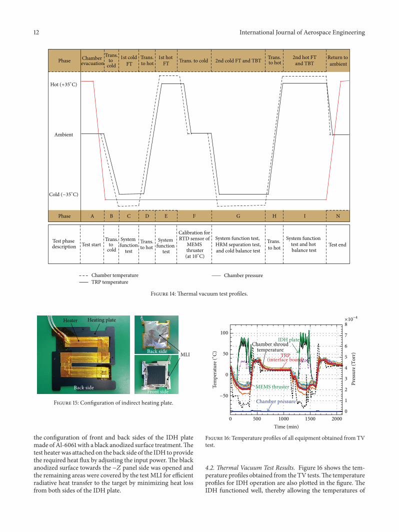
Figure 14 shows the TV test profiles applied to the systemfunctional verification of the STEP Cube Lab. During the TVtest, full system functional tests were conducted at both hot
and cold soak phases to check the state of health and verifynormal functionality in the space simulated thermal vacuumenvironment. In the last cold soak phase of G in Figure 14,a separation test of the HRM was conducted because this isthe worst condition for HRM activation.Themicroresistancetemperature detector (RTD) of the MEMS thruster wascalibrated with the temperature data directly acquired by thethermocouples from TV chamber data acquisition systemduring three temperature stabilization periods. The accuracyof the sensor is not important because the data is used foronly monitoring the status of the thruster on-orbit. Hot andcold thermal balance tests at soak phases of G and I ofFigure 14 were conducted to obtain the balanced temperaturedata used for obtaining highly reliable TMMof the satellite bycorrelating the model with the test data.
The feature of the TV test performed in this study is toapply an indirect heating (IDH) plate as shown in Figure 15,to more effectively simulate the different temperature con-ditions of each panel on-orbit. For example, if the TRPtemperature reached the target cold temperature threshold,there was a possibility that the temperature of the MEMSthruster and battery near the thruster was excessively coolerthan the predicted on-orbit temperature; the IDH installednear theMEMS thruster as shown in Figure 15 provided localheat flux to the −𝑍 side of the CubeSat. Figure 15 shows
12 International Journal of Aerospace Engineering
Calibration for RTD sensor of
MEMS thruster
System function test, HRM separation test, and cold balance test
F G
Trans. to hot
System function
test
D E
Test phase description Test start
Trans.to
cold
System function
test
B CPhase A
Trans. to cold 2nd cold FT and TBTChamber evacuation
Ambient
PhaseTrans.
to cold
1st cold FT
Trans. to hot
1st hot FT
Return to ambient
Test end
N
Trans. to hot
2nd hot FTand TBT
H I
Trans. to hot
System function test and hot balance test
Hot (+35∘C)
Cold (−35∘C)
(at 10∘C)
Chamber temperatureTRP temperature
Chamber pressure
Figure 14: Thermal vacuum test profiles.
Back side
Front sideBack side
Heating plateHeater
MLI
Figure 15: Configuration of indirect heating plate.
the configuration of front and back sides of the IDH platemade of Al-6061 with a black anodized surface treatment.Thetest heaterwas attached on the back side of the IDH to providethe required heat flux by adjusting the input power.The blackanodized surface towards the −𝑍 panel side was opened andthe remaining areas were covered by the test MLI for efficientradiative heat transfer to the target by minimizing heat lossfrom both sides of the IDH plate.
Chamber pressure
TRP(interface board)
IDH plateChamber shroud
temperature
MEMS thruster
500 1000 1500 20000Time (min)
×10−4
100
50
0
−50
0
1
2
3
4
5
6
7
8
Pres
sure
(Tor
r)
Tem
pera
ture
(∘C)
Figure 16: Temperature profiles of all equipment obtained from TVtest.
4.2. Thermal Vacuum Test Results. Figure 16 shows the tem-perature profiles obtained from the TV tests.The temperatureprofiles for IDH operation are also plotted in the figure. TheIDH functioned well, thereby allowing the temperatures of

International Journal of Aerospace Engineering 13
1360 1380 1400 14201340Time (min)
−34
−33
−32
−31
−30
−29Te
mpe
ratu
re (∘
C)
Fixed emittance radiatorVariable emittance radiator
(a)
420 440 460 480 500 520Time (min)
28
30
32
34
36
38
Tem
pera
ture
(∘C)
Fixed emittance radiatorVariable emittance radiator
(b)
Figure 17: Temperature profiles of the VER and EFR ((a) transition to cold test phase, (b) transition to hot test phase).
the MEMS thruster and battery on the −𝑍 direction of theCubeSat to be locally controlled as intended by the IDHdesign. The test results indicated that the TV test was suc-cessfully conducted in accordance with the established testprofiles shown in Figure 16, within acceptance temperaturethresholds. In addition, system functional tests were suc-cessfully performed at maximum and minimum acceptancetemperature plateaus without any anomalies, although thedetailed test results are not described in this paper.
Figures 17(a) and 17(b) show an enlarged view of thetemperature profiles obtained from the fixed and variableemittance radiators under hot and cold conditions. In alltest phases, a temperature difference between the variableand fixed emittance radiators was observed.The temperaturevalues from the VER under hot and cold conditions showedlower andhigher values than the FER, respectively, because itsemissivity varied according to the environment temperature.However, the difference was small compared with that of on-orbit thermal analysis results shown in Figure 11 because thetest temperature variation was limited to smaller range of−35∘C to 35∘C. Additionally, the reduction of radiating areacaused by attaching thermocouples to the radiator surfacehaving a small area of 9 cm2 also contributed to these results.Detailed characteristics of the radiator will be investigated bythe STEP Cube Lab mission through on-orbit temperaturedata acquisition.
Figure 18 shows the temperature profile from the PCMinstalled on the payload plate. To verify the effectiveness ofthe PCM, the temperature from the payload plate is alsoplotted in the figure. The results clearly show the thermalcharacteristics of the PCM, which stores and releases latentheat according to the phase change characteristics of thematerial at 10∘C as expected. In addition, no leakages ofthe working fluid during the test periods were observed,thereby verifying the sealing method of the PCM. The phase
PCMPayload board
Phase change
1200 1280 1360 1440 1520 1600 16801120Time (min)
−30
−20
−10
0
10
20
30
Tem
pera
ture
(∘C)
Figure 18: Temperature profile of the PCM.
change characteristics of the PCM will be verified throughcontinuous temperature monitoring on-orbit.
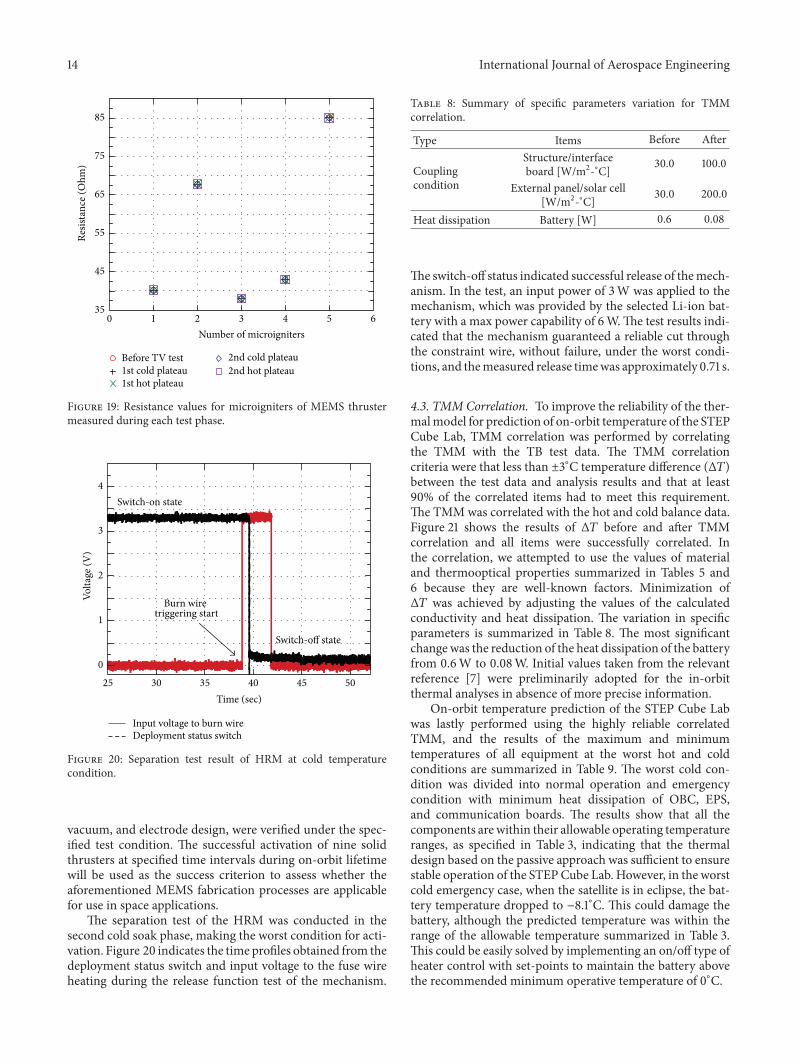
To verify the survivability of the MEMS thruster ina thermal vacuum environment, resistance values of themicroigniters were measured and compared before and afterat each test phase. The variation of the resistance values forthe microigniters was less than 0.7% during all test phases asshown in Figure 19.This indicates that theMEMS fabricationprocesses of the solid thruster array, that is, the sputteringof the Pt/Ti heater, diffusion bonding of the photosensitiveglass, ultraviolet (UV) bonding, solid propellant filling under
14 International Journal of Aerospace Engineering
Before TV test1st cold plateau1st hot plateau
2nd cold plateau2nd hot plateau
35
45
55
65
75
85
Resis
tanc
e (O
hm)
1 2 3 4 5 60Number of microigniters
Figure 19: Resistance values for microigniters of MEMS thrustermeasured during each test phase.
25 30 35 40 45 50
Input voltage to burn wireDeployment status switch
Time (sec)
Burn wire triggering start
Switch-on state
Switch-off state
0
1
2
3
4
Volta
ge (V
)
Figure 20: Separation test result of HRM at cold temperaturecondition.
vacuum, and electrode design, were verified under the spec-ified test condition. The successful activation of nine solidthrusters at specified time intervals during on-orbit lifetimewill be used as the success criterion to assess whether theaforementioned MEMS fabrication processes are applicablefor use in space applications.
The separation test of the HRM was conducted in thesecond cold soak phase, making the worst condition for acti-vation. Figure 20 indicates the time profiles obtained from thedeployment status switch and input voltage to the fuse wireheating during the release function test of the mechanism.
Table 8: Summary of specific parameters variation for TMMcorrelation.
Type Items Before After
Couplingcondition
Structure/interfaceboard [W/m2-∘C] 30.0 100.0
External panel/solar cell[W/m2-∘C] 30.0 200.0
Heat dissipation Battery [W] 0.6 0.08
The switch-off status indicated successful release of themech-anism. In the test, an input power of 3W was applied to themechanism, which was provided by the selected Li-ion bat-tery with a max power capability of 6W.The test results indi-cated that the mechanism guaranteed a reliable cut throughthe constraint wire, without failure, under the worst condi-tions, and themeasured release timewas approximately 0.71 s.
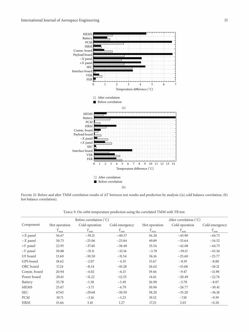
4.3. TMM Correlation. To improve the reliability of the ther-malmodel for prediction of on-orbit temperature of the STEPCube Lab, TMM correlation was performed by correlatingthe TMM with the TB test data. The TMM correlationcriteria were that less than ±3∘C temperature difference (Δ𝑇)between the test data and analysis results and that at least90% of the correlated items had to meet this requirement.The TMMwas correlated with the hot and cold balance data.Figure 21 shows the results of Δ𝑇 before and after TMMcorrelation and all items were successfully correlated. Inthe correlation, we attempted to use the values of materialand thermooptical properties summarized in Tables 5 and6 because they are well-known factors. Minimization ofΔ𝑇 was achieved by adjusting the values of the calculatedconductivity and heat dissipation. The variation in specificparameters is summarized in Table 8. The most significantchangewas the reduction of the heat dissipation of the batteryfrom 0.6W to 0.08W. Initial values taken from the relevantreference [7] were preliminarily adopted for the in-orbitthermal analyses in absence of more precise information.
On-orbit temperature prediction of the STEP Cube Labwas lastly performed using the highly reliable correlatedTMM, and the results of the maximum and minimumtemperatures of all equipment at the worst hot and coldconditions are summarized in Table 9. The worst cold con-dition was divided into normal operation and emergencycondition with minimum heat dissipation of OBC, EPS,and communication boards. The results show that all thecomponents are within their allowable operating temperatureranges, as specified in Table 3, indicating that the thermaldesign based on the passive approach was sufficient to ensurestable operation of the STEPCube Lab. However, in the worstcold emergency case, when the satellite is in eclipse, the bat-tery temperature dropped to −8.1∘C. This could damage thebattery, although the predicted temperature was within therange of the allowable temperature summarized in Table 3.This could be easily solved by implementing an on/off type ofheater control with set-points to maintain the battery abovethe recommended minimum operative temperature of 0∘C.
International Journal of Aerospace Engineering 15
FERVER
Interface boardSEC
+X panel−X panel
Payload boardComm. board
HRMPCM
BatteryMEMS
After correlationBefore correlation
1 2 3 4 5 6 70Temperature difference (∘C)
(a)
After correlationBefore correlation
0 1 2 3 4 5 6 7 8 9 10 11 12 13 14FERVER
Interface boardSEC
+X panel−X panel
Payload boardComm. board
HRMPCM
BatteryMEMS
Temperature difference (∘C)
(b)
Figure 21: Before and after TMM correlation results of Δ𝑇 between test results and prediction by analysis ((a) cold balance correlation, (b)hot balance correlation).
Table 9: On-orbit temperature prediction using the correlated TMM with TB test.
ComponentBefore correlation (∘C) After correlation (∘C)
Hot operation Cold operation Cold emergency Hot operation Cold operation Cold emergency𝑇max 𝑇min 𝑇min 𝑇max 𝑇min 𝑇min
+𝑋 panel 56.67 −39.21 −40.57 56.20 −43.90 −44.75−𝑋 panel 50.75 −25.06 −25.84 49.89 −33.64 −34.52+𝑌 panel 22.95 −37.40 −38.40 33.54 −42.08 −44.75−𝑌 panel 30.88 −31.11 −32.16 −3.78 −39.13 −43.36I/F board 13.60 −30.50 −31.54 36.16 −25.60 −25.77GPS board 18.62 −2.07 −4.35 15.67 −8.19 −8.80OBC board 17.24 −8.54 −10.28 26.62 −15.68 −18.21Comm. board 20.94 −4.02 −6.13 19.46 −9.47 −11.98Power board 20.61 −11.22 −12.55 14.61 −20.49 −22.76Battery 35.78 −1.38 −3.49 26.90 −3.78 −8.07MEMS 25.67 −3.71 −4.79 30.96 −26.77 −30.41SEC 67.63 −29.68 −30.50 58.20 −35.20 −36.18PCM 19.71 −3.16 −5.23 19.52 −7.18 −9.39HRM 15.66 3.10 1.27 17.25 2.03 −0.20

16 International Journal of Aerospace Engineering
Table 10: On-orbit temperature prediction after thermal design modification on the battery.
ComponentWithout MLI on the battery (∘C) With MLI on the battery (∘C)
Hot operation Cold operation Cold emergency Hot operation Cold operation Cold emergency𝑇max 𝑇min 𝑇min 𝑇max 𝑇min 𝑇min
+𝑋 panel 56.20 −43.90 −44.75 56.88 −44.12 −44.29−𝑋 panel 49.89 −33.64 −34.52 52.15 −34.39 −34.41+𝑌 panel 33.54 −42.08 −44.75 33.52 −41.90 −43.06−𝑌 panel −3.78 −39.13 −43.36 −2.37 −40.32 −40.58I/F board 36.16 −25.60 −25.77 37.96 −25.51 −25.75GPS board 15.67 −8.19 −8.80 18.24 −7.21 −9.91OBC board 26.62 −15.68 −18.21 27.30 −15.53 −16.10Comm. board 19.46 −9.47 −11.98 20.35 −9.55 −10.83Power board 14.61 −20.49 −22.76 18.32 −20.47 −21.20Battery 26.90 −3.78 −8.07 27.81 2.64 1.84MEMS 30.96 −26.77 −30.41 29.46 −28.27 −28.57SEC 58.20 −35.20 −36.18 59.45 −36.18 −36.04PCM 19.52 −7.18 −9.39 20.36 −7.44 −8.64HRM 17.25 2.03 −0.20 17.26 1.82 0.60
However, in this study, we propose the application ofMLIto the battery in order to minimize the design modificationsto the existing CubeSat flight model already verified throughenvironment tests. The thermal analysis results summarizedin Table 10 showed that the minimum temperature of thebattery increased to 1.84∘C by applying the MLI at the worstcold emergency condition.The calculatedmaximum temper-ature at the worst hot operation condition was 27.81∘C, witha margin of 32∘C, with respect to the requirement of +60∘C.Accessing to the battery is very easy as it is located in closeproximity to the MEMS thruster, as shown in Figure 8(b).Therefore, the additional MLI installation on the batterycan be easily accomplished by demating the MEMS thrustermodule on flexure-like brackets as shown in Figure 1(b),without demating the remaining parts of the CubeSat.
5. Conclusion
This paper describes thermal design and validation of a 1Ustandardized pico-class satellite of STEP Cube Lab developedfor the purpose of on-orbit verification of technical resultsfrom space-related research conducted in domestic univer-sities. In this paper, firstly, a system overview of the STEPCube Lab, including the description of five payloads, wasintroduced. Next, the thermal design to guarantee successfulmission objective by satisfying the temperature requirementof on-board equipment was described, and the effectivenessof the thermal design and the main functions of the STEPCube Lab were verified under space simulated thermal vac-uumenvironment.One of the features of thermal vacuum testperformed in this study was to use an indirect heating plateto simulate on-orbit temperature condition of the satellite.In addition, a correlated thermal mathematical model of theSTEP Cube Lab with higher reliability was created by usingexperimental data obtained from thermal balance test. On-orbit thermal analysis results based on the correlated thermal
mathematical model shows that the thermal design based onthe passive approach ensures stable operation of the systemwithin allowable operating temperature ranges.
Competing Interests
The authors declare that they have no competing interests.
Acknowledgments
This research was supported by a research fund (2015) byChosun University.
References
[1] H. Heidt, J. Puig-Suari, A. S. Moore, S. Nakasuka, and R.J. Twiggs, “CubeSat: a new generation of picosatellite foreducation and industry low-cost space experimentation,” inProceeding the 14th Annual AIAA/USU Conference on SmallSatellites, vol. 32, Logan, Utah, USA, August 2000.
[2] M. Komatsu and S. Nakasuka, “University of Tokyo nanosatellite project PRISM,” Transactions of the Japan Society forAeronautical and Space Sciences, vol. 7, no. 26, pp. 19–24, 2009.
[3] M.W. Smith, S. Seager, C. M. Pong et al., “ExoplanetSat: detect-ing transiting exoplanets using a low-cost CubeSat platform,”in Space Telescopes and Instrumentation: Optical, Infrared, andMillimeter Wave, vol. 7731 of Proceedings of the SPIE, pp. 66–78,San Diego, Calif, USA, July 2010.
[4] C. J. Fong, A. Lin, A. Shie et al., “Lessons learned of NSPO’sPicosatellite Mission: YamSat—1A, 1B & 1C,” in Proceedings ofthe 16thAnnual AIAA/USUConference on Small Satellite, no. 60,The American Institute of Aeronautics and Astronautics, 2002.
[5] V. Baturkin, “Micro-satellites thermal control—concepts andcomponents,” Acta Astronautica, vol. 56, no. 1-2, pp. 161–170,2005.
[6] J. Yoo,H. Jin, J. Seon et al., “Thermal analysis of TRIO-CINEMAmission,” Journal of Astronomy and Space Science, vol. 29, no. 1,pp. 23–31, 2012.
International Journal of Aerospace Engineering 17
[7] W. Ley, E. Plescher, A. Scholz, and J. Piepenbrock, “COMPASS-1picosatellite project,” in Proceedings of the 16th IAA Symposiumon Small Satellites for Earth Observation, 2007.
[8] A. Scholz, W. Ley, B. Dachwald, J. J. Miau, and J. C. Juang,“Flight results of the COMPASS-1 picosatellite mission,” ActaAstronautica, vol. 67, no. 9-10, pp. 1289–1298, 2010.
[9] S. Corpino, M. Caldera, F. Nichele, M. Masoero, and N. Viola,“Thermal design and analysis of a nanosatellite in low earthorbit,” Acta Astronautica, vol. 115, pp. 247–261, 2015.
[10] E. Escobar, M. Diaz, and J. Zagal, “Design automation forsatellite passive thermal control,” in Proceedings of the 4SSymposium, Portoroz, Slovenia, June 2012.
[11] Y. Shimakawa, T. Yoshitake, Y. Kubo et al., “A variable-emittanceradiator based on a metal-insulator transition of (La,Sr)MnO3thin films,” Applied Physics Letters, vol. 80, no. 25, pp. 4864–4866, 2002.
[12] A. Kumar, A. Sekar, D. N. Siddhartha, and K. V. Govinda,“Phase change materials (PCM) for thermal control duringspacecraft transportation,” International Journal of Mechanicaland Industrial Engineering, vol. 3, no. 1, pp. 28–32, 2013.
[13] D. G. Gilmore, Spacecraft Thermal Control Handbook, Volume1: Fundamental Technologies, The Aerospace Corporation, 2ndedition, 2002.
[14] H.-U. Oh and T. Y. Park, “Experimental feasibility study of con-centrating photovoltaic power system for cubesat applications,”IEEE Transactions on Aerospace and Electronic Systems, vol. 51,no. 3, pp. 1942–1949, 2015.
[15] J. K. Lee, K. H. Kim, and S. J. Kwon, “Design, fabrication andtesting of MEMS solid propellant thruster array chip on glasswafer,” Journal of Sensors and Actuators A: Physical, vol. 157, no.1, pp. 126–134, 2010.
[16] M. J. Lee, Y. K. Lee, and H. U. Oh, “Performance evaluationof hinge driving separation nut-type holding and releasingmechanism triggered by nichrome burn wire,” InternationalJournal of Aeronautical and Space Sciences, vol. 16, no. 4, pp.602–613, 2015.
[17] A. R. Samir,Passive attitude stabilization for small satellites [M.S.thesis], University of Kentucky, Lexington, Ky, USA, 2010.
[18] http://www.gomspace.com/.[19] T. D. Panczak, S. G. Ring, M. J. Welch, D. Johnson, B. A.
Cullimore, and D. P. Bell, Thermal Desktop User’s Manual, C &R Technologies, 2008.
[20] F.M.Michael,RadiativeHeat Transfer,TheAcademic Press, 2ndedition, 2003.
[21] K. Shimazaki, A. Ohnishi, and Y. Nagasaka, “Development ofspectral selective multilayer film for a variable emittance deviceand its radiation properties measurements,” International Jour-nal of Thermophysics, vol. 24, no. 3, pp. 757–769, 2003.

International Journal of
AerospaceEngineeringHindawi Publishing Corporationhttp://www.hindawi.com Volume 2014
RoboticsJournal of
Hindawi Publishing Corporationhttp://www.hindawi.com Volume 2014
Hindawi Publishing Corporationhttp://www.hindawi.com Volume 2014
Active and Passive Electronic Components
Control Scienceand Engineering
Journal of
Hindawi Publishing Corporationhttp://www.hindawi.com Volume 2014
International Journal of
RotatingMachinery
Hindawi Publishing Corporationhttp://www.hindawi.com Volume 2014
Hindawi Publishing Corporation http://www.hindawi.com
Journal ofEngineeringVolume 2014
Submit your manuscripts athttp://www.hindawi.com
VLSI Design
Hindawi Publishing Corporationhttp://www.hindawi.com Volume 2014
Hindawi Publishing Corporationhttp://www.hindawi.com Volume 2014
Shock and Vibration
Hindawi Publishing Corporationhttp://www.hindawi.com Volume 2014
Civil EngineeringAdvances in
Acoustics and VibrationAdvances in
Hindawi Publishing Corporationhttp://www.hindawi.com Volume 2014
Hindawi Publishing Corporationhttp://www.hindawi.com Volume 2014
Electrical and Computer Engineering
Journal of
Advances inOptoElectronics
Hindawi Publishing Corporation http://www.hindawi.com
Volume 2014
The Scientific World JournalHindawi Publishing Corporation http://www.hindawi.com Volume 2014
SensorsJournal of
Hindawi Publishing Corporationhttp://www.hindawi.com Volume 2014
Modelling & Simulation in EngineeringHindawi Publishing Corporation http://www.hindawi.com Volume 2014
Hindawi Publishing Corporationhttp://www.hindawi.com Volume 2014
Chemical EngineeringInternational Journal of Antennas and
Propagation
International Journal of
Hindawi Publishing Corporationhttp://www.hindawi.com Volume 2014
Hindawi Publishing Corporationhttp://www.hindawi.com Volume 2014
Navigation and Observation
International Journal of
Hindawi Publishing Corporationhttp://www.hindawi.com Volume 2014
DistributedSensor Networks
International Journal of


![Orbit type: Sun Synchronous Orbit ] Orbit height: …...Orbit type: Sun Synchronous Orbit ] PSLV - C37 Orbit height: 505km Orbit inclination: 97.46 degree Orbit period: 94.72 min ISL](https://img.pdfslide.net/doc/110x75/5f781053e671b364921403bc/orbit-type-sun-synchronous-orbit-orbit-height-orbit-type-sun-synchronous.jpg)


![Research Article On-Orbit Thermal Design and Validation …2019-7-30 · phasechangematerial(PCM)[,]forverifyingthermal control equipment, a solar energy collection (SEC) system](https://img.pdfslide.net/doc/110x75/6122d46dec541c627174044e/research-article-on-orbit-thermal-design-and-validation-2019-7-30aaphasechangematerialpcmforverifyingthermal.jpg)