Embed Size (px)
Citation preview
Research ArticleOn Stability of Open-Loop Operation without RotorInformation for Brushless DC Motors
Zhong Wu,1 Haotun Lyu,1 Yongli Shi,2 and Di Shi1
1 School of Instrumentation Science and Optoelectronics Engineering, Beihang University, Beijing 100191, China2 Beijing Institute of Control Engineering, Chinese Academy of Space Technology, Beijing 100190, China
Correspondence should be addressed to Zhong Wu; [email protected]
Received 17 February 2014; Accepted 8 June 2014; Published 1 July 2014
Academic Editor: Alexei Mailybaev
Copyright © 2014 Zhong Wu et al. This is an open access article distributed under the Creative Commons Attribution License,which permits unrestricted use, distribution, and reproduction in any medium, provided the original work is properly cited.
Open-loop operation mode is often used to control the Brushless DC Motors (BLDCMs) without rotor position sensors when theback electromotive force (EMF) is too weak due to the very low rotor velocity. The rotor position information is not necessary inthis mode and the stator windings are supplied with voltages under a certain ratio of the amplitude to the frequency. However, therotor synchronization will be destroyed once if the commutation instant is inappropriate. In order to improve the reliability of theopen-loop operation mode, a dynamic equation is established to represent the synchronization error between the rotor and thestator. Thereafter, the stability of the open-loop control mode is analyzed by using Lyapunov indirect method. Theoretical analysisindicates that the open-loop control mode is asymptotically stable only when the commutation instant of the stator current lagsbehind the ideal one suitably. Finally, theoretical analysis is verified through the experimental results of a certain BLDCM.
1. Introduction
The Brushless DC Motor (BLDCM) is an AC synchronousmotor with a permanent-magnet rotor and can be electron-ically commutated. Due to their advantages of smaller size,higher efficiency, simpler structure, easier control, and higherperformance, BLDCMs have been widely used in manyfields [1, 2], such as aerospace, military equipment, electricalvehicles, CNCmachines, computer peripherals, instruments,and domestic appliances.
In order to realize high-performance control of BLDCMs,the rotor position sensors are often mounted in the motorsto obtain the information of the rotor position and velocity.However, the existence of the rotor position sensors will notonly increase the size, weight, and the cost but also decreasethe reliability of the motor systems. Even if the simpleswitch-mode hall position sensor is used, the reliability cannot be guaranteed in the environment of high temperature,strong vibration, and strong corrosion. Sensorless control ofBLDCMs is a feasible solution to the applications in the harshenvironment as well as high-reliability concerns [2, 3].
Among the various sensorless control strategies for BLD-CMs, the back electromotive force (EMF) method has been
widely used to detect the rotor position due to its ease ofimplementation [4, 5]. However, the effective information ofthe rotor position is difficult to be derived from theweak backEMF when the motor is standstill or operates at a very lowvelocity. In such cases, the open-loop operationmode is oftenused to control the motors. In this mode, the rotor positioninformation is not necessary and the stator windings aresupplied with voltages under a certain ratio of the amplitudeto the frequency (i.e., 𝑉/𝑓). However, the rotor synchroniza-tion will be destroyed by the improper commutation instantresulting from the improper𝑉/𝑓. Especially in the BLDCMsof large inertia or heavy load, the stability problem of theopen-loop operation mode is quite serious.
Early in the 1980s, the operation stability of the per-manent magnet synchronous motors (PMSM) was analyzedtheoretically by the authors in [6, 7]. After that, a methodof adjusting the ratio of voltage to frequency was proposedbased on the analysis of its effects on the stability of PMSMsin [8, 9]. Matsui [10] also proposed a method to start themotor according to the information of the winding voltageand current directly. However, these studies only focused onthe PMSMswith sinusoidal back EMF and the BLDCMswithtrapezoidal back EMF are not involved.
Hindawi Publishing CorporationMathematical Problems in EngineeringVolume 2014, Article ID 740498, 7 pageshttp://dx.doi.org/10.1155/2014/740498
2 Mathematical Problems in Engineering
For the BLDCMs with trapezoidal back EMF, manyalgorithms were proposed to smooth the starting procedurefrom standstill to aminimum speed at which the back EMF islarge enough to provide the information of the rotor position[11–17]. However, few of them dealt with the problem ofoperation stability for BLDCMs. Although Shen and Tsengmentioned the relationship between the commutation angleand the operation performance in [4], the detailed theoreticalanalysis is not available.
The motivation of this paper is to demonstrate thestability condition through theoretical analysis and improvethe reliability of the open-loop operationmode for BLDCMs.Hence, a dynamic equation is established to represent thesynchronization error between the rotor and the stator at first.Thereafter, the stability of the open-loop operation mode isanalyzed by using Lyapunov indirect method.The remainingparts of the paper are organized as follows. In Section 2, abrief description of the principles and stability problem ofthe open-loop mode for BLDCMs will be given. In Section 3,a dynamic equation representing the synchronization errorbetween the rotor and the stator will be established forBLDCMs, and then the mean electromagnetic torque relyingon the commutation angle is derived. In Section 4, thestability of the open-loop operationmode will be analyzed byusing Lyapunov indirect method. In Section 5, experimentalresults of a certain BLDCM drive are presented to verify thestability condition obtained in this paper. Finally, conclusionsare made in Section 6.
2. Problem Description
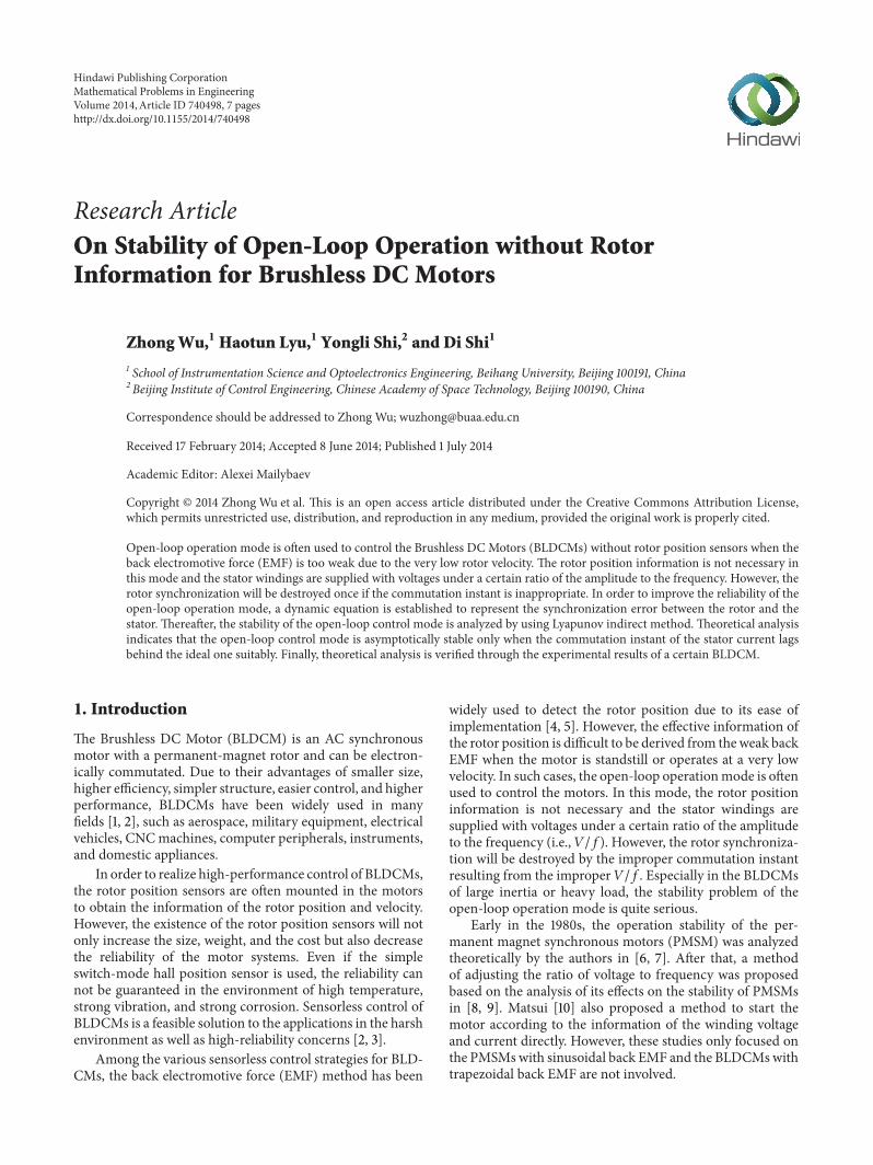
2.1. Principles of Open-Loop OperationMode for BLDCMs. Inthe sensorless control of BLDCMs based on the detectionof the back EMF, the open-loop operation mode is oftenused to start and accelerate the motor since the back EMFis too weak to provide the information of the rotor positionwhen the motor is standstill or operates at a very low speed.In this mode, the stator windings are energized accordingto the commutation state machine instead of the actualrotor position, as shown in Figure 1. The commutation statemachine driven by a signal with ramp frequency contains6 fixed states in a certain sequence and the initial onedepends on the prepositioning pulse or the predeterminedrotor position. The supplied voltage varies with the rampfrequency at a certain ratio, also known as the variable-voltage variable-frequency control. Furthermore, the ratio of𝑉/𝑓 should be designed properly according to the motor andthe load parameters so that the rotor can be forced to followthe ramp frequency by the enough electromagnetic torque.
However, the rotor is difficult to follow the variation ofthe stator current rapidly due to its large time constant for theBLDCM with large inertia or heavy load. Once an improperratio of 𝑉/𝑓 is used, the rotor will tend to oscillate and evenstep out due to the improper commutation instant. Thus, astarting failure is incurred. Therefore, the stability should beanalyzed theoretically to improve the reliability of the open-loop operation mode for BLDCMs.
Switch logicA
B
CD
E
F
t
f
PWMgenerator
Initialstate
Ramp frequency
Commutationstate machine
A
B C
BLDCM
V/f
T1 T2 T3
T4 T5 T6
Figure 1: Schematics of open-loop operation mode.
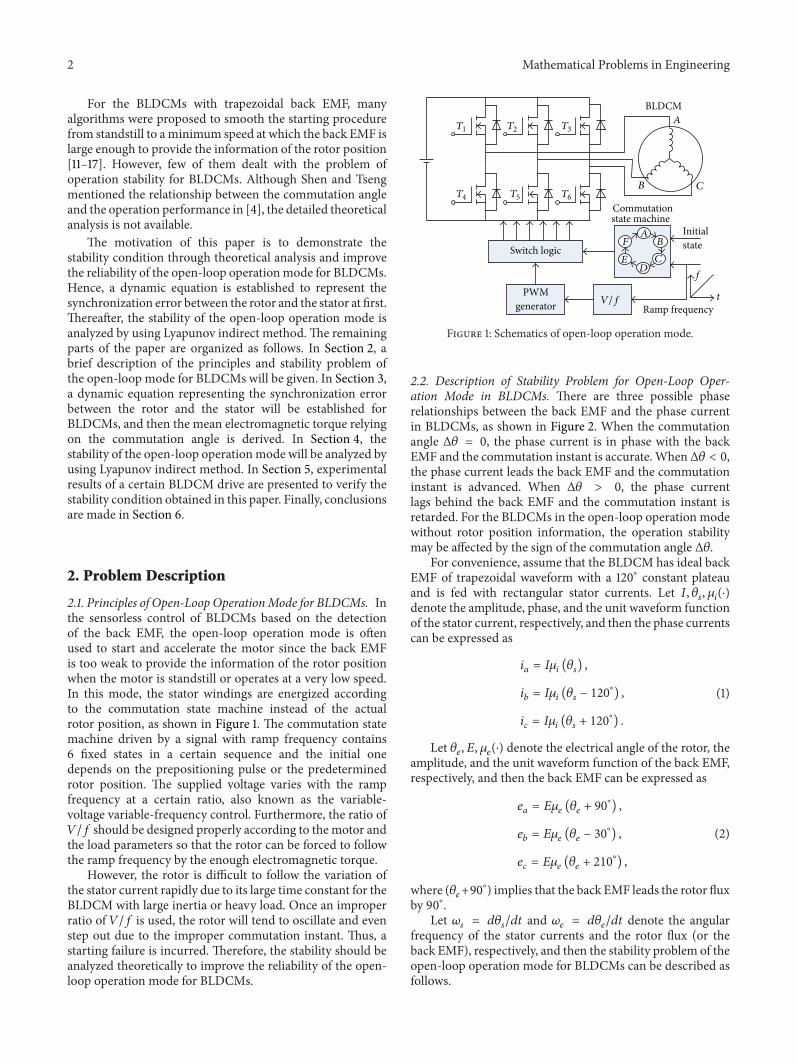
2.2. Description of Stability Problem for Open-Loop Oper-ation Mode in BLDCMs. There are three possible phaserelationships between the back EMF and the phase currentin BLDCMs, as shown in Figure 2. When the commutationangle Δ𝜃 = 0, the phase current is in phase with the backEMF and the commutation instant is accurate. When Δ𝜃 < 0,the phase current leads the back EMF and the commutationinstant is advanced. When Δ𝜃 > 0, the phase currentlags behind the back EMF and the commutation instant isretarded. For the BLDCMs in the open-loop operation modewithout rotor position information, the operation stabilitymay be affected by the sign of the commutation angle Δ𝜃.
For convenience, assume that the BLDCM has ideal backEMF of trapezoidal waveform with a 120∘ constant plateauand is fed with rectangular stator currents. Let 𝐼, 𝜃
𝑠, 𝜇𝑖(⋅)
denote the amplitude, phase, and the unit waveform functionof the stator current, respectively, and then the phase currentscan be expressed as
𝑖𝑎= 𝐼𝜇𝑖(𝜃𝑠) ,
𝑖𝑏= 𝐼𝜇𝑖(𝜃𝑠− 120
∘
) ,
𝑖𝑐= 𝐼𝜇𝑖(𝜃𝑠+ 120
∘
) .
(1)
Let 𝜃𝑒, 𝐸, 𝜇𝑒(⋅) denote the electrical angle of the rotor, the
amplitude, and the unit waveform function of the back EMF,respectively, and then the back EMF can be expressed as
𝑒𝑎= 𝐸𝜇𝑒(𝜃𝑒+ 90∘
) ,
𝑒𝑏= 𝐸𝜇𝑒(𝜃𝑒− 30∘
) ,
𝑒𝑐= 𝐸𝜇𝑒(𝜃𝑒+ 210
∘
) ,
(2)
where (𝜃𝑒+90∘
) implies that the back EMF leads the rotor fluxby 90∘.
Let 𝜔𝑠= 𝑑𝜃𝑠/𝑑𝑡 and 𝜔
𝑒= 𝑑𝜃𝑒/𝑑𝑡 denote the angular
frequency of the stator currents and the rotor flux (or theback EMF), respectively, and then the stability problem of theopen-loop operation mode for BLDCMs can be described asfollows.
Mathematical Problems in Engineering 3
ea
ia
𝜃e
(a) Accurate commutation (Δ𝜃 = 0)
ea
ia
𝜃e
Δ𝜃
Δ𝜃
(b) Advanced commutation (Δ𝜃 < 0)
ea
ia
𝜃e
Δ𝜃
Δ𝜃
(c) Retarded commutation (Δ𝜃 > 0)
Figure 2: Different commutation conditions.
If both the speed synchronization differenceΔ𝜔 = 𝜔𝑒−𝜔𝑠
and the commutation angle Δ𝜃 = 90∘
+ 𝜃𝑒− 𝜃𝑠are bounded
asymptotically, the BLDCM will be stable in the open-loopoperation mode without the rotor position information.
Obviously, the bounded Δ𝜔 ensures the synchronizationbetween the rotor flux (or the back EMF) and the statorcurrents, while the boundedΔ𝜃 ensures the production of theelectromagnetic torque large enough to maintain the stableoperation of the motor.
3. Mathematical Models
3.1. Error Dynamics of Rotor Synchronization. In order toanalyze the stability of the BLDCM in the open-loop oper-ation mode, mathematical models should be established torepresent the synchronization error between the rotor andthe stator. Considering a BLDCM with a surface-mountedpermanent-magnet rotor and 3-phase wye-connected sym-metric stator windings, neglecting the salient and slot effects,the magnetic saturation, and the losses due to hysteresis andeddy current, then the electromagnetic torque can be writtenas
𝑇𝑒=
1
𝜔(𝑒𝑎𝑖𝑎+ 𝑒𝑏𝑖𝑏+ 𝑒𝑐𝑖𝑐) , (3)
where𝜔 is the angular speed of the rotor. According to (1)–(3),it is known that the electromagnetic torque depends on notonly the current amplitude but also the phase difference Δ𝜃between the back EMF and the stator currents.Themaximumof the electromagnetic torque can be achieved only whenΔ𝜃 = 0.
Actuated by the torque in (3), the rotor motion can bedescribed as
𝐽𝑑𝜔
𝑑𝑡= 𝑇𝑒(Δ𝜃) − 𝑇
𝐿− 𝐷𝜔, (4)
where𝑇𝑒(Δ𝜃) denotes the torque function ofΔ𝜃 and 𝐽,𝐷, and
𝑇𝐿are the moment of inertia, damping coefficient, and the
load torque, respectively.From (4), the dynamic equation representing the syn-
chronization error between the rotor and the stator can bederived as
Δ ̇𝜃 = Δ𝜔,
Δ�̇� =𝑝
𝐽𝑇𝑒(Δ𝜃) −
𝐷
𝐽Δ𝜔 −
𝑝
𝐽𝑇𝐿−𝐷
𝐽𝜔𝑠− �̇�𝑠,
(5)
where 𝑝 is the number of pole pairs.Henceforth, the problem of stability analysis for the
BLDCMs in the open-loop operation mode can be trans-formed into the qualitative study on the nonlinear ordinarydifferential equation (5).
3.2. Derivation of Mean Electromagnetic Torque Relying onCommutation Angle. In order to analyze the stability ofthe open-loop operation mode based on (5), the analyticalexpression of 𝑇
𝑒(Δ𝜃) should be given first. For the BLDCMs
with trapezoidal back EMF, the rotor flux linkages 𝜓𝑟𝑎, 𝜓𝑟𝑏,
and 𝜓𝑟𝑐can be written as [18–20]
[
[
𝜓𝑟𝑎
𝜓𝑟𝑏
𝜓𝑟𝑐
]
]
= 𝜓𝑟𝑚
∞
∑
𝑛=1
𝑘2𝑛−1
[
[
sin ((2𝑛 − 1) 𝜃𝑒)
sin ((2𝑛 − 1) (𝜃𝑒− 120
∘
))
sin ((2𝑛 − 1) (𝜃𝑒+ 120
∘
))
]
]
, (6)
where𝜓𝑟𝑚
is themagnitude of the fundamental component ofthe permanentmagnet flux linkage, 𝑘
𝑛is the coefficient of the
𝑛th flux harmonic relative to the fundamental, and 𝑘1= 1. For
3-phase wye-connected symmetric stator windings, the evenharmonics, the third harmonic, and its multiples are canceledout in (6).
4 Mathematical Problems in Engineering
Replace the back EMF with the rotor flux linkages in (3),we can get
𝑇𝑒= 𝑝[
𝑑𝜓𝑟𝑎(𝜃𝑒)
𝑑𝜃𝑒
𝑖𝑎+𝑑𝜓𝑟𝑏(𝜃𝑒)
𝑑𝜃𝑒
𝑖𝑏+𝑑𝜓𝑟𝑐(𝜃𝑒)
𝑑𝜃𝑒
𝑖𝑐] . (7)
Substitute (6) into (7), and then the electromagnetictorque in presence of back EMF harmonics can be expressedas
𝑇𝑒= 𝜓𝑟𝑚
∞
∑
𝑛=1
𝑘2𝑛−1
(2𝑛 − 1) i𝑇[[
cos ((2𝑛 − 1) 𝜃𝑒)
cos ((2𝑛 − 1) (𝜃𝑒− 120
∘
))
cos ((2𝑛 − 1) (𝜃𝑒+ 120
∘
))
]
]
,
(8)
where i = [𝑖𝑎, 𝑖𝑏, 𝑖𝑐]𝑇.
Since the analytical relationship between 𝑇𝑒and Δ𝜃 is
difficult to be derived from (8) in the 3-phase stationaryreference frame, it can be expressed in the synchronouslyrotating 𝑑-𝑞 reference frame. After 𝑑-𝑞 transformation, thefundamental component of flux linkage is transformed intoa dc component, while the 5th and the 7th harmonics aretransformed into the 6th harmonic, the 11th and the 13thharmonics are transformed into the 12th harmonic, the17th and the 19th harmonics are transformed into the 18thharmonic, and so on [19]. Then the electromagnetic torquein 𝑑-𝑞 reference frame can be expressed as [18]
𝑇𝑒=
3𝑝
2𝜓𝑟𝑚
[𝑖𝑞(1 + ℎ
𝑑) + 𝑖𝑑ℎ𝑞] , (9)
where 𝑖𝑑, 𝑖𝑞are stator currents in 𝑑-𝑞 frame, ℎ
𝑑, ℎ𝑞are
higher-order harmonics of rotor flux in d-q frame, and
ℎ𝑑=
∞
∑
𝑛=1
[(6𝑛 − 1) 𝑘6𝑛−1
+ (6𝑛 + 1) 𝑘6𝑛+1
] cos (6𝑛𝜃𝑒) ,
ℎ𝑞=
∞
∑
𝑛=1
[(6𝑛 − 1) 𝑘6𝑛−1
− (6𝑛 + 1) 𝑘6𝑛+1
] sin (6𝑛𝜃𝑒) .
(10)
Owing to the infinite series and rectangular-waveformcurrents in (9), it is too complicated to find out the analyticalexpression of the commutation angle Δ𝜃. Hereby, the meanvalues of the rotor flux and the stator currents during acommutation interval can be used to simplify (9).
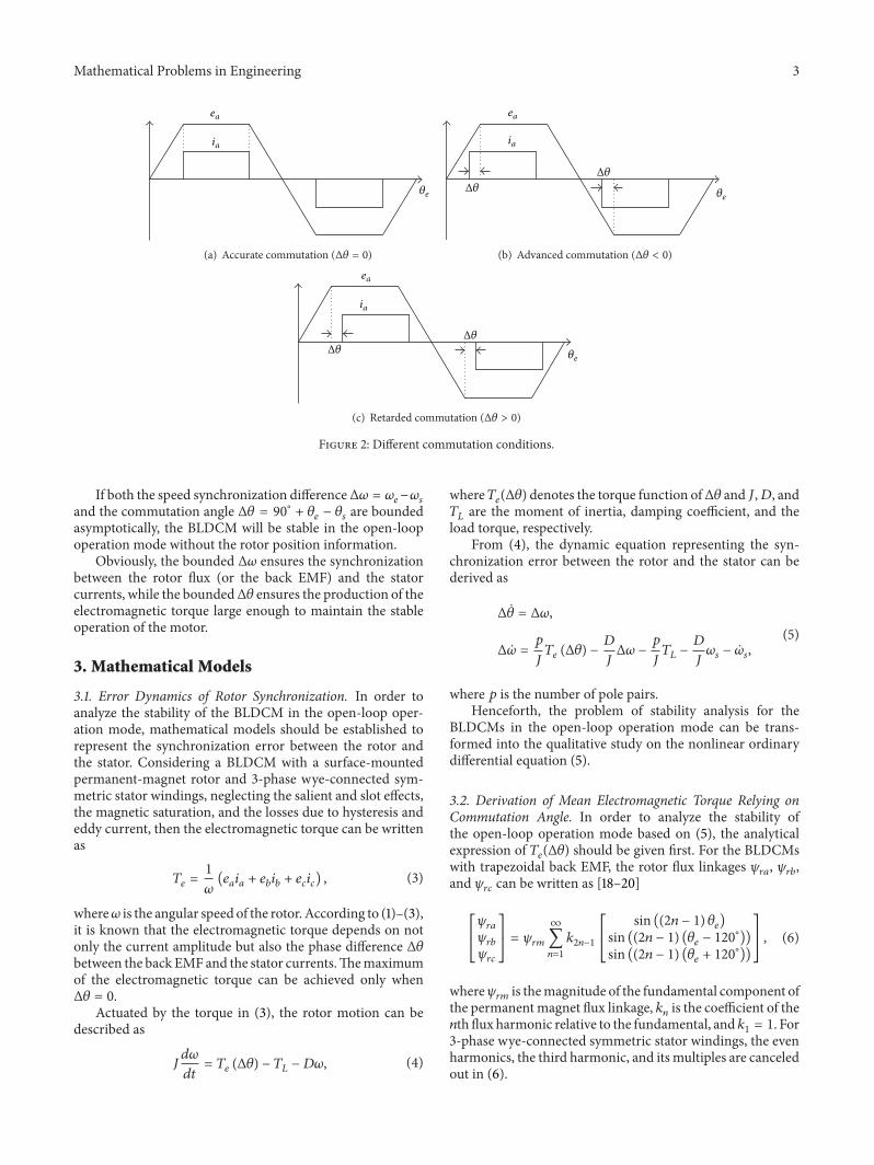
As shown in Figure 3, the rotor along 𝑑-axis rotatescontinuously at a speed of 𝜔
𝑒while the stator current i
steps forward every 60∘ with an average speed of 𝜔𝑠. The
intersection angle between 𝑞-axis and i is (Δ𝜃 − 30∘
) at thebeginning and (Δ𝜃 + 30
∘
) at the end of the commutationinterval. Let 𝛾 denote an angle in [−30∘, 30∘], and then theintersection angle can be represented by (Δ𝜃 + 𝛾) during acertain commutation interval. Thus, the mean values of thestator current i in the 𝑑- and 𝑞-axes can be derived as
𝑖𝑞=
3
𝜋∫
𝜋/6
−𝜋/6
𝐼 cos (Δ𝜃 + 𝛾) 𝑑𝛾 =3
𝜋𝐼 cosΔ𝜃,
𝑖𝑑=
3
𝜋∫
𝜋/6
−𝜋/6
𝐼 sin (Δ𝜃 + 𝛾) 𝑑𝛾 =3
𝜋𝐼 sinΔ𝜃.
(11)
i
𝛼
q
𝛽
d
i
𝜓rq𝜓rd
Δ𝜃Δ𝜃+𝛾
𝜃s𝜃e
𝜔s
𝜔e
Figure 3: Schematics of stator current and rotor flux.
Correspondingly, the mean values of the higher-orderharmonics ℎ
𝑑and ℎ
𝑞during a certain commutation interval
also can be derived from (10) as follows:
ℎ𝑑=
3
𝜋∫
𝜃0+𝜋/3
𝜃0
ℎ𝑑𝑑𝜃𝑒= 0,
ℎ𝑞=
3
𝜋∫
𝜃0+𝜋/3
𝜃0
ℎ𝑞𝑑𝜃𝑒= 0,
(12)
where 𝜃0is the angular position of the rotor at the beginning
of the commutation interval.Replacing 𝑖
𝑑, 𝑖𝑞, ℎ𝑑, ℎ𝑞with their mean values 𝑖
𝑑, 𝑖𝑞, ℎ𝑑, ℎ𝑞
in (9), then the mean electromagnetic torque can be achievedas
𝑇𝑒=
9𝑝
2𝜋𝜓𝑟𝑚𝐼 cosΔ𝜃. (13)
Obviously, the explicit function of the electromagnetictorque relying on the commutation angle Δ𝜃 is given in (13).
4. Stability of Open-Loop Operation
If the electromagnetic torque 𝑇𝑒is replaced with its mean
value 𝑇𝑒, the error dynamics (5) of the open-loop operation
mode for BLDCMs can be changed into
Δ ̇𝜃 = Δ𝜔,
Δ�̇� =9𝑝2
2𝜋𝐽𝜓𝑟𝑚𝐼 cosΔ𝜃 − 𝐷
𝐽Δ𝜔 −
𝑝
𝐽𝑇𝐿−𝐷
𝐽𝜔𝑠− �̇�𝑠.
(14)
Obviously, the error dynamics in (14) is nonlinear. Forthe stability of nonlinear dynamical systems, various resultshave been derived in [21–27]. For convenience, the stabilityof (14) can be analyzed by using Lyapunov indirect method.Linearize (14) at the initial commutation angle Δ𝜃
0, and then
the following linearized error dynamics can be achieved as
[Δ ̇𝜃
Δ�̇�] = 𝐴[
Δ𝜃
Δ𝜔] −
1
𝐽[
0
𝑝𝑇𝐿+ 𝐷𝜔𝑠+ 𝐽�̇�𝑠
] , (15)
where 𝐴 = [0 1
−9𝑝
2/2𝜋𝐽⋅𝜓𝑟𝑚𝐼 sinΔ𝜃0 −𝐷/𝐽 ].
Mathematical Problems in Engineering 5
The characteristic equation of the state matrix 𝐴 can beexpressed as
𝜆2
+𝐷
𝐽𝜆 +
9𝑝2
2𝜋
𝜓𝑟𝑚𝐼
𝐽sinΔ𝜃
0= 0. (16)
According to Lyapunov indirect method, the conclusionsconcerning the operation stability of BLDCMs are derivedfrom (16) as follows.
When Δ𝜃0< 0 (i.e., advanced commutation), system (14)
is instable and the motor can not operate in the open-loopmode without rotor position information stably since there isan eigenvalue with positive real part in (16).
WhenΔ𝜃0> 0 (i.e., retarded commutation), system (14) is
asymptotically stable and the motor can operate in the open-loop mode without rotor position information stably sinceboth two eigenvalues of (16) have negative real parts.
When Δ𝜃0= 0 (i.e., accurate commutation), the stability
of system (14) can not be judged from the linearized system(15) since one eigenvalue of (16) is 0 and the other hasnegative real part. Even if system (14) is marginally stable,its robustness to the disturbances is very poor. Once thecommutation angle Δ𝜃 turns to be negative owing to certaindisturbances, the motor will lose stability and the reliabilityof the open-loop operation mode can not be guaranteed. Incontrast, the BLDCM in the self-control mode (commutatedwith the rotor information) not only operates stably but alsocan realize maximal electromagnetic torque, minimal power,and the highest efficiency when Δ𝜃
0= 0.
According to the aforementioned analyses, it is clear thatthe commutation instant of the stator currents should lagbehind the ideal one suitably so as to realize stable operationof the BLDCM in the open-loop mode. In the practicalsystems, the energized voltage should be large enough toproduce enough electromagnetic torque which can drive therotor advanced.
Compared with the relative studies, the main contribu-tion of this paper is to overcome the difficulties in analyzingthe operation stability by using the error dynamics with themean electromagnetic torque and demonstrate the stabilityconditions of the open-loop mode for BLDCMs. In partic-ular, it is pointed out that the stability of the open-loopmode is sensitive to the disturbances during the accuratecommutation and the reliability can not be guaranteed.
5. Experimental Results
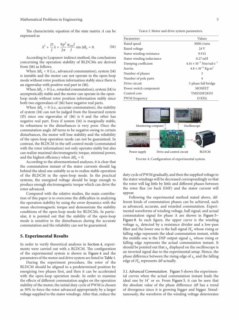
In order to verify theoretical analyses in Section 4, experi-ments were carried out with a BLDCM. The configurationof the experimental system is shown in Figure 4 and theparameters of themotor and drive system are listed in Table 1.
During the experiment procedure, the rotor of theBLDCM should be aligned to a predetermined position byenergizing two phases first, and then it can be acceleratedwith the open-loop operation mode. In order to examinethe effects of different commutation angles on the operationstability of the motor, the initial duty cycle of PWM is chosenas 30% to force the rotor advanced appropriately by a largervoltage supplied to the stator windings. After that, reduce the
Table 1: Motor and drive system parameters.
Parameters ValuesRated speed 3000 r/minRated voltage 24VStator winding resistance 0.9ΩStator winding inductance 0.27mHDamping coefficient 4.14 × 10⁻⁵ Nm/rad⋅s−1
Inertia 4.8 × 10⁻⁶ Kg⋅m2
Number of phases 3Number of pole pairs 4Drive circuit 3-phase full bridgePower switch component MOSFETControl core TMS320F28335PWM frequency 15 KHz
Monitoring computer Oscilloscope
Power supply Drive and control circuit BLDCM
Figure 4: Configuration of experimental system.
duty cycle of PWMgradually, and then the supplied voltage tothe stator windings will be decreased correspondingly so thatthe rotor will lag little by little and different phases betweenthe rotor flux (or back EMF) and the stator current willappear.
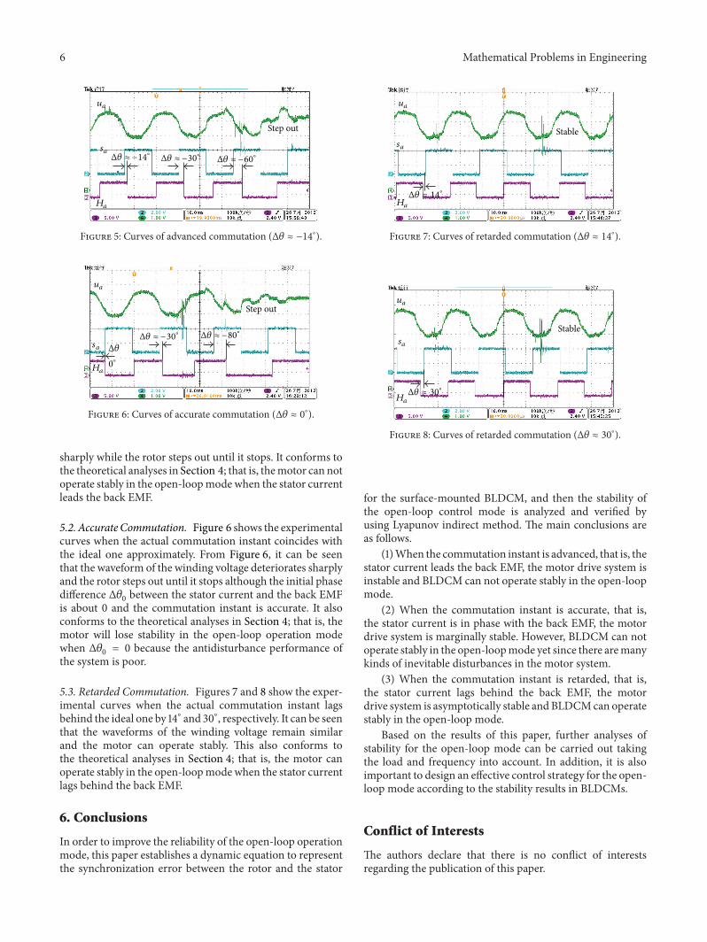
Following the experimental method stated above, dif-ferent kinds of commutation phases can be achieved, suchas advanced, accurate, and retarded commutation. Experi-mental waveforms of winding voltage, hall signal, and actualcommutation signal for phase A are shown in Figure 5∼Figure 8. In each figure, the upper curve is the windingvoltage 𝑢
𝑎detected by a resistance divider and a low-pass
filter and the lower one is the hall signal 𝐻𝑎whose rising or
falling edge represents the ideal commutation instant, whilethe middle one is the DSP output signal 𝑠
𝑎whose rising or
falling edge represents the actual commutation instant. Itshould be pointed out that 𝑠
𝑎displayed on the oscilloscope is
an inverted signal due to the experimental setup. Hence, thephase difference between the rising edge of 𝑠
𝑎and the falling
edge of𝐻𝑎represents Δ𝜃 actually.
5.1. Advanced Commutation. Figure 5 shows the experimen-tal curves when the actual commutation instant leads theideal one by 14∘ or so. From Figure 5, it can be seen thatthe absolute value of the phase difference Δ𝜃 has a trendof divergence since it is growing bigger and bigger. Simul-taneously, the waveform of the winding voltage deteriorates
6 Mathematical Problems in Engineering
ua
sa
Ha
Step out
Δ𝜃 ≈ −14∘ Δ𝜃 ≈ −30∘ Δ𝜃 ≈ −60∘
Figure 5: Curves of advanced commutation (Δ𝜃 ≈ −14∘
).
ua
sa
Ha
Step out
Δ𝜃
0∘
Δ𝜃 ≈ −30∘ Δ𝜃 ≈ −80∘
Figure 6: Curves of accurate commutation (Δ𝜃 ≈ 0∘
).
sharply while the rotor steps out until it stops. It conforms tothe theoretical analyses in Section 4; that is, themotor can notoperate stably in the open-loopmode when the stator currentleads the back EMF.
5.2. Accurate Commutation. Figure 6 shows the experimentalcurves when the actual commutation instant coincides withthe ideal one approximately. From Figure 6, it can be seenthat the waveform of the winding voltage deteriorates sharplyand the rotor steps out until it stops although the initial phasedifference Δ𝜃
0between the stator current and the back EMF
is about 0 and the commutation instant is accurate. It alsoconforms to the theoretical analyses in Section 4; that is, themotor will lose stability in the open-loop operation modewhen Δ𝜃
0= 0 because the antidisturbance performance of
the system is poor.
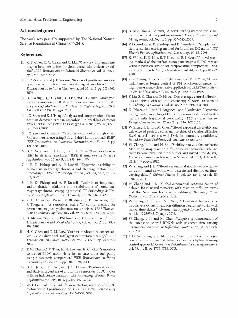
5.3. Retarded Commutation. Figures 7 and 8 show the exper-imental curves when the actual commutation instant lagsbehind the ideal one by 14∘ and 30∘, respectively. It can be seenthat the waveforms of the winding voltage remain similarand the motor can operate stably. This also conforms tothe theoretical analyses in Section 4; that is, the motor canoperate stably in the open-loopmode when the stator currentlags behind the back EMF.
6. Conclusions
In order to improve the reliability of the open-loop operationmode, this paper establishes a dynamic equation to representthe synchronization error between the rotor and the stator
ua
sa
Ha
Δ𝜃 ≈ 14∘
Stable
Figure 7: Curves of retarded commutation (Δ𝜃 ≈ 14∘
).
ua
sa
Ha
Stable
Δ𝜃 ≈ 30∘
Figure 8: Curves of retarded commutation (Δ𝜃 ≈ 30∘
).
for the surface-mounted BLDCM, and then the stability ofthe open-loop control mode is analyzed and verified byusing Lyapunov indirect method. The main conclusions areas follows.
(1)When the commutation instant is advanced, that is, thestator current leads the back EMF, the motor drive system isinstable and BLDCM can not operate stably in the open-loopmode.
(2) When the commutation instant is accurate, that is,the stator current is in phase with the back EMF, the motordrive system is marginally stable. However, BLDCM can notoperate stably in the open-loopmode yet since there aremanykinds of inevitable disturbances in the motor system.
(3) When the commutation instant is retarded, that is,the stator current lags behind the back EMF, the motordrive system is asymptotically stable and BLDCMcan operatestably in the open-loop mode.
Based on the results of this paper, further analyses ofstability for the open-loop mode can be carried out takingthe load and frequency into account. In addition, it is alsoimportant to design an effective control strategy for the open-loop mode according to the stability results in BLDCMs.
Conflict of Interests
The authors declare that there is no conflict of interestsregarding the publication of this paper.
Mathematical Problems in Engineering 7
Acknowledgment
The work was partially supported by The National NaturalScience Foundation of China (10772011).
References
[1] K. T. Chau, C. C. Chan, and C. Liu, “Overview of permanent-magnet brushless drives for electric and hybrid electric vehi-cles,” IEEE Transactions on Industrial Electronics, vol. 55, no. 6,pp. 2246–2257, 2008.
[2] P. P. Acarnley and J. F. Watson, “Review of position-sensorlessoperation of brushless permanent-magnet machines,” IEEETransactions on Industrial Electronics, vol. 53, no. 2, pp. 352–362,2006.
[3] D. F. Wang, J. Qi, C. Zhu, J. G. Liao, and Y. C. Yuan, “Strategy ofstarting sensorless BLDCM with inductance method and EMFintegration,” Mathematical Problems in Engineering, vol. 2013,Article ID 146058, 8 pages, 2013.
[4] J. X. Shen and K. J. Tseng, “Analyses and compensation of rotorposition detection error in sensorless PM brushless dc motordrives,” IEEE Transactions on Energy Conversion, vol. 18, no. 1,pp. 87–93, 2003.
[5] J. X. Shen and S. Iwasaki, “Sensorless control of ultrahigh-speedPM brushless motor using PLL and third harmonic back EMF,”IEEE Transactions on Industrial Electronics, vol. 53, no. 2, pp.421–428, 2006.
[6] G. C. Verghese, J. H. Lang, and L. F. Casey, “Analysis of insta-bility in electrical machines,” IEEE Transactions on IndustryApplications, vol. 22, no. 5, pp. 853–864, 1986.
[7] I. E. D. Pickup and A. P. Russell, “Dynamic instability inpermanent-magnet synchronous and stepping motors,” IEEProceedings B: Electric Power Applications, vol. 134, no. 2, pp. 91–100, 1987.
[8] I. E. D. Pickup and A. P. Russell, “Analysis of frequency-and amplitude-modulation in the stabilisation of permanent-magnet synchronous/steppingmotors,” IEE Proceedings B: Elec-tric Power Applications, vol. 139, no. 4, pp. 336–346, 1992.
[9] P. D. Chandana Perera, F. Blaabjerg, J. K. Pedersen, andP. Thøgersen, “A sensorless, stable V/f control method forpermanent-magnet synchronous motor drives,” IEEE Transac-tions on Industry Applications, vol. 39, no. 3, pp. 783–791, 2003.
[10] N. Matsui, “Sensorless PM brushless DC motor drives,” IEEETransactions on Industrial Electronics, vol. 43, no. 2, pp. 300–308, 1996.
[11] H.-C. Chen and C.-M. Liaw, “Current-mode control for sensor-less BDCM drive with intelligent commutation tuning,” IEEETransactions on Power Electronics, vol. 17, no. 5, pp. 747–756,2002.
[12] T. W. Chun, Q. V. Tran, H. H. Lee, and H. G. Kim, “Sensorlesscontrol of BLDC motor drive for an automotive fuel pumpusing a hysteresis comparator,” IEEE Transactions on PowerElectronics, vol. 29, no. 3, pp. 1382–1391, 2014.
[13] G. H. Jang, J. H. Park, and J. H. Chang, “Position detectionand start-up algorithm of a rotor in a sensorless BLDC motorutilising inductance variation,” IEE Proceedings: Electric PowerApplications, vol. 149, no. 2, pp. 137–142, 2002.
[14] W. J. Lee and S. K. Sul, “A new starting method of BLDCmotors without position sensor,” IEEE Transactions on IndustryApplications, vol. 42, no. 6, pp. 1532–1538, 2006.
[15] B. Asaei and A. Rostami, “A novel starting method for BLDCmotors without the position sensors,” Energy Conversion andManagement, vol. 50, no. 2, pp. 337–343, 2009.
[16] P. Damodharan, R. Sandeep, and K. Vasudevan, “Simple posi-tion sensorless starting method for brushless DC motor,” IETElectric Power Applications, vol. 2, no. 1, pp. 49–55, 2008.
[17] K. W. Lee, D. K. Kim, B. T. Kim, and B. I. Kwon, “A novel start-ing method of the surface permanent-magnet BLDC motorswithout position sensor for reciprocating compressor,” IEEETransactions on Industry Applications, vol. 44, no. 1, pp. 85–92,2008.
[18] S.-K. Chung, H.-S. Kim, C.-G. Kim, and M.-J. Youn, “A newinstantaneous torque control of PM synchronous motor forhigh-performance direct-drive applications,” IEEE Transactionson Power Electronics, vol. 13, no. 3, pp. 388–400, 1998.
[19] Y. Liu, Z. Q. Zhu, and D. Howe, “Direct torque control of brush-less DC drives with reduced torque ripple,” IEEE Transactionson Industry Applications, vol. 41, no. 2, pp. 599–608, 2005.
[20] K. Tabarraee, J. Iyer, H. Atighechi, and J. Jatskevich, “Dynamicaverage-value modeling of 120∘ VSI-commutated brushless DCmotors with trapezoidal back EMF,” IEEE Transactions onEnergy Conversion, vol. 27, no. 2, pp. 296–307, 2012.
[21] W. Zhang, J. Li, and M. Chen, “Global exponential stability andexistence of periodic solutions for delayed reaction-diffusionBAM neural networks with Dirichlet boundary conditions,”Boundary Value Problems, vol. 2013, article 105, 2013.
[22] W. Zhang, J. Li, and N. Shi, “Stability analysis for stochasticMarkovian jump reaction-diffusion neural networks with par-tially known transition probabilities and mixed time delays,”Discrete Dynamics in Nature and Society, vol. 2012, Article ID524187, 17 pages, 2012.
[23] W. Zhang and J. Li, “Global exponential stability of reaction—diffusion neural networks with discrete and distributed time-varying delays,” Chinese Physics B, vol. 20, no. 3, Article ID030701, 2011.
[24] W. Zhang and J. Li, “Global exponential synchronization ofdelayed BAM neural networks with reaction-diffusion termsand the Neumann boundary conditions,” Boundary ValueProblems, vol. 2012, article 2, 2012.
[25] W. Zhang, J. Li, and M. Chen, “Dynamical behaviors ofimpulsive stochastic reaction-diffusion neural networks withmixed time delays,” Abstract and Applied Analysis, vol. 2012,Article ID 236562, 21 pages, 2012.
[26] W. Zhang, J. Li, and M. Chen, “Adaptive synchronization ofthe stochastic delayed RDNNs with unknown time-varyingparameters,” Advances in Difference Equations, vol. 2013, article253, 2013.
[27] J. Li, W. Zhang, and M. Chen, “Synchronization of delayedreaction-diffusion neural networks via an adaptive learningcontrol approach,”Computers &Mathematics with Applications,vol. 65, no. 11, pp. 1775–1785, 2013.

Submit your manuscripts athttp://www.hindawi.com
Hindawi Publishing Corporationhttp://www.hindawi.com Volume 2014
MathematicsJournal of
Hindawi Publishing Corporationhttp://www.hindawi.com Volume 2014
Mathematical Problems in Engineering
Hindawi Publishing Corporationhttp://www.hindawi.com
Differential EquationsInternational Journal of
Volume 2014
Applied MathematicsJournal of
Hindawi Publishing Corporationhttp://www.hindawi.com Volume 2014
Probability and StatisticsHindawi Publishing Corporationhttp://www.hindawi.com Volume 2014
Journal of
Hindawi Publishing Corporationhttp://www.hindawi.com Volume 2014
Mathematical PhysicsAdvances in
Complex AnalysisJournal of
Hindawi Publishing Corporationhttp://www.hindawi.com Volume 2014
OptimizationJournal of
Hindawi Publishing Corporationhttp://www.hindawi.com Volume 2014
CombinatoricsHindawi Publishing Corporationhttp://www.hindawi.com Volume 2014
International Journal of
Hindawi Publishing Corporationhttp://www.hindawi.com Volume 2014
Operations ResearchAdvances in
Journal of
Hindawi Publishing Corporationhttp://www.hindawi.com Volume 2014
Function Spaces
Abstract and Applied AnalysisHindawi Publishing Corporationhttp://www.hindawi.com Volume 2014
International Journal of Mathematics and Mathematical Sciences
Hindawi Publishing Corporationhttp://www.hindawi.com Volume 2014
The Scientific World JournalHindawi Publishing Corporation http://www.hindawi.com Volume 2014
Hindawi Publishing Corporationhttp://www.hindawi.com Volume 2014
Algebra
Discrete Dynamics in Nature and Society
Hindawi Publishing Corporationhttp://www.hindawi.com Volume 2014
Hindawi Publishing Corporationhttp://www.hindawi.com Volume 2014
Decision SciencesAdvances in
Discrete MathematicsJournal of
Hindawi Publishing Corporationhttp://www.hindawi.com
Volume 2014 Hindawi Publishing Corporationhttp://www.hindawi.com Volume 2014
Stochastic AnalysisInternational Journal of