Embed Size (px)
Citation preview
Research ArticleReal-Time Implementation of Islanded Microgrid forRemote Areas
Monika Jain,1 Sushma Gupta,1 Deepika Masand,2 Gayatri Agnihotri,1 and Shailendra Jain1
1Department of Electrical Engineering, Maulana Azad National Institute of Technology (MANIT), Bhopal 462003, India2Department of Electrical & Electronics Engineering, Oriental Institute of Science & Technology (OIST), Bhopal 462021, India
Correspondence should be addressed to Monika Jain; [email protected]
Received 9 November 2015; Revised 6 February 2016; Accepted 15 February 2016
Academic Editor: Qiaoling Tong
Copyright © 2016 Monika Jain et al. This is an open access article distributed under the Creative Commons Attribution License,which permits unrestricted use, distribution, and reproduction in any medium, provided the original work is properly cited.
Islanding is a condition in which a microgrid or a portion of power grid, consisting of distributed generation (DG) sources,converter, and load, gets disconnected from the utility grid. Under this condition the DG sources in a microgrid must switch to avoltage control mode, in order to provide constant voltage to local loads. In grid connected mode, the microgrid works as currentcontroller and injects power to the main grid, depending on the power generation and local load with suitable market policies.Providing constant voltage at a stable frequency with proper synchronization amongst each DG in a microgrid is a challenge.The complexity of such grid requires careful study and analysis before actual implementation. These challenges of microgrid areaddressed using real time OPAL-RT simulation technology. Thus the paper describes an islanded microgrid with master slavecontroller for power balance, voltage/frequency regulation, and synchronization. Based on an advanced real-time platform namedReal-Time Laboratory (RT-LAB), the impacts of the micro sources, load, and converters in an islanded microgrid is studied in thispaper.The effectiveness of the proposed controller is analyzed through experimental results under balanced/unbalanced nonlinearloads condition.
1. Introduction
Regular depletion of conventional energy sources has ledthe society to think of other alternative resources whichwill continue to cater the increasing demand of energy. Onesuch alternative is an accretion of small scale renewableresources to form a microgrid and supply to a regional area[1, 2]. Microgrid can operate in two distinct modes: (1) gridconnected and (2) islanded (autonomous) mode. In gridconnected mode, the microgrid works as current controllerand injects power to the main grid, depending on the powergeneration and local load with suitable market policies [3].Microgrid can come in islanded/autonomous mode due todisturbances, such as a fault and its subsequent switchingincidents, or due to preplanned switching events or dueto unavailability of resources. In islanded mode, microgridworks as voltage controller and is responsible for voltagecontrol as well as for power sharing and balancing. The roleof power sharing features is to ensure that all modules sharethe load according to their rating and availability of power
from their energy source. In islandedmode converters alwaysrequire grid-forming (master) power converters; otherwisethere is no voltage reference and no control to maintainthe power balance. In the single master operation, one unitoperates as a grid-forming converter. The other units operateas grid-following units. In the multimaster operation, morethan one unit is grid-forming, possibly combined with grid-feeding converters. In this work one of the units (DG) isacting as master controller and other units are acting as aslave controller.Themaster DGoperates as voltage controlledsource and the rest of them as slave DGs which operate ascurrent controller. The master controller works like grid-forming power converters and the main aim is to regulatethe voltage and frequency of the microgrid. The slave DGswork like grid-feeding power converters and are controlledas current source, allowing active and reactive power mod-ulation depending on voltage and frequency measurementsat their Point of Common Coupling (PCC). Therefore, thiskind of converter cannot operate independently in islandmode [4, 5]. Since a microgrid comprises a number of
Hindawi Publishing CorporationJournal of Control Science and EngineeringVolume 2016, Article ID 5710950, 9 pageshttp://dx.doi.org/10.1155/2016/5710950
2 Journal of Control Science and Engineering
micro sources, their synchronization with each other is animportant task.When interconnecting themicrogridwith themain grid, many authors have developed the synchronizationalgorithms [6–8] considering each micro source as a DCsource. But in a microgrid maintaining constant voltageand frequency, each micro source is an important issue inaddition to synchronization. This paper proposes a master-slave controller for synchronization/resynchronization of allthe DGs, regulation of voltage/frequency, and effective powersharing among the micro sources. The islanded microgrid isformed by two DG units. Each unit consists of Self-ExcitedInduction Generator (SEIG) driven by ABB drive, controller,battery for storage, and load. The impact of the paralleloperated DG units has to be carefully studied and analyzedbefore actual realization. This is achieved with the helpof real-time simulation platform; the Real-Time Laboratory(RT-LAB) developed by OPAL-RT Technologies [9–11].
2. System Configuration
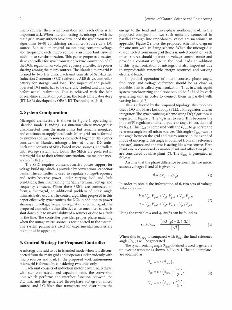
Microgrid architecture is shown in Figure 1, operating inislanded mode. Islanding is a situation where microgrid isdisconnected from the main utility but remains energizedand continues to supply local loads. Microgrid can be formedby numbers of micro sources connected together. This paperconsiders an islanded microgrid formed by two DG units.Each unit consists of SEIG based micro sources, controllerswith storage system, and loads. The SEIGs are preferred inmicrogrid due to their robust construction, less maintenance,and so forth [12, 13].
The SEIG requires constant reactive power support forvoltage build up, which is provided by conventional capacitorbanks. The controller is used to regulate voltage/frequencyand active/reactive power under varying load and faultconditions, thus maintaining the SEIG terminal voltage andfrequency constant. When these SEIGs are connected toform a microgrid, an additional problem of phase anglemismatch also occurs.The control algorithmproposed in thispaper effectively synchronizes the DGs in addition to powersharing and voltage/frequency regulation in a microgrid.Theproposed controller is also effective when onemicro source isshut down due to unavailability of resources or due to a faultin the line. The controller provides proper phase matchingwhen the outage micro source is reconnected to the system.The system parameters used for experimental analysis arementioned in appendix.
3. Control Strategy for Proposed Controller
Amicrogrid is said to be in islanded mode when it is discon-nected from themain grid and it operates independently withmicro sources and load. In the proposed work autonomousmicrogrid is formed by considering two units only.
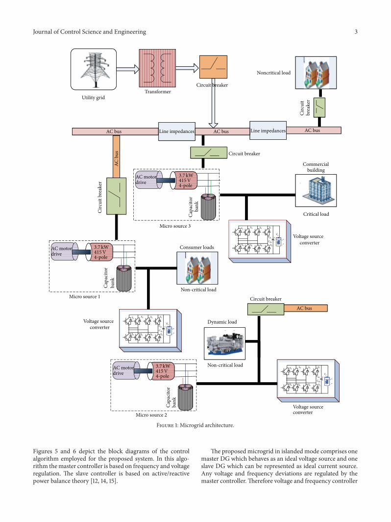
Each unit consists of induction motor driven ABB drive,with star connected fixed capacitor bank, the conversionunit which performs the interface function between theDC link and the generated three-phase voltages of microsource, and LC filter that transports and distributes the
energy to the load and three-phase nonlinear load. In theproposed configuration two such units are connected inparallel through line impedances; values are mentioned inappendix. Figure 2 shows the proposed schematic diagramfor one unit with its firing scheme. When the microgrid isdisconnected frommain grid that is islanded condition, eachmicro source should operate in voltage control mode andprovide a constant voltage to the local loads. In additionto this, synchronization of microgrid is also important dueto unpredictable renewable energy resources and varyingelectrical loads.
In parallel operation of micro sources, phase angle,frequency, and voltage difference should be as close aspossible. This is called synchronization. Thus in a microgridsystem synchronizing conditions should be fulfilled by eachgenerating unit in order to connect them in parallel withvarying load [6, 7].
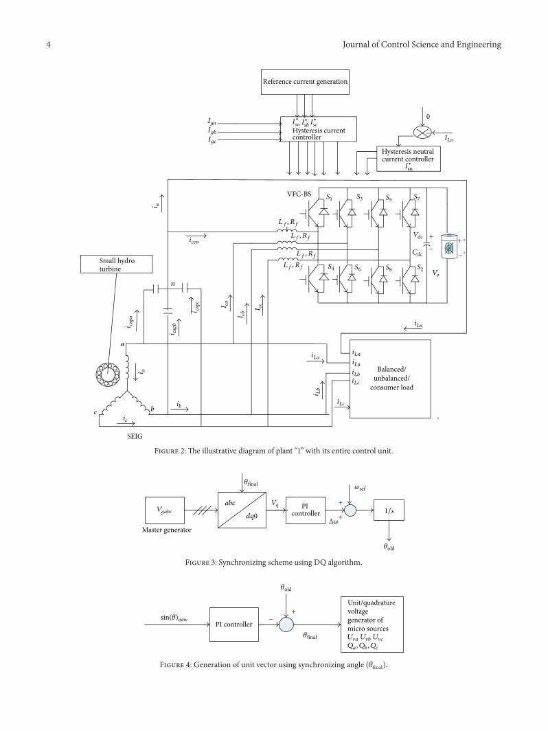
This is achieved by the proposed topology. This topologyuses a DQ and Phase Lock Loop (PLL), a PI regulator, and anintegrator. The synchronizing scheme using DQ algorithm isdepicted in Figure 3. The 𝑉𝑞 is set to zero. This becomes theinput of PI regulator and its output is an angle (theta, denotedby 𝜃old). This 𝜃old is compared with the 𝜃new to generate thereference angle for all micro sources.This angle (𝜃new) can bethe angle between the grid and micro source; in the islandedmode of microgrid this angle is obtained from any reference(master) source and the rest is acting like slave source. Hereplant one is considered as master plant and other two plantsare considered as slave plant [7]. The 𝜃new is generated asfollows.
Assume that the phase difference between the two microsources voltages (1 and 2) is given by
𝜃 = ∠𝑉𝑔1 − ∠𝑉𝑔2. (1)
In order to obtain the information of 𝜃, two sets of voltagevalues are used:
𝑘 = 𝑉𝑔𝑎1𝑉𝑔𝑎2 + 𝑉𝑔𝑏1𝑉𝑔𝑏2 + 𝑉𝑔𝑐1𝑉𝑔𝑐2,
𝑔 = 𝑉𝑔𝑎1𝑉𝑔𝑏3 + 𝑉𝑔𝑏1𝑉𝑔𝑐3 + 𝑉𝑔𝑐1𝑉𝑔𝑎3.
(2)
Using the variables 𝑘 and 𝑔, sin(𝜃) can be found as
sin (𝜃)new =[4/3 (g) + 2/3 (k)][√3]
. (3)
When this (𝜃)new is compared with 𝜃old, the final referenceangle (𝜃final) will be generated.
The synchronizing angle 𝜃final obtained is used to generateunit vector template as shown in Figure 4.The unit templatesare obtained as
𝑈V𝑎 = sin (𝜃final) ,
𝑈V𝑏 = sin(𝜃final −2𝜋
3) ,
𝑈V𝑐 = sin(𝜃final +2𝜋
3) .
(4)
Journal of Control Science and Engineering 3
Consumer loads
Voltage source converter
AC motordrive
Capa
cito
rba
nk
Micro source 1
Line impedances Line impedances AC bus AC bus AC bus
AC motordrive
Capa
cito
rba
nk
AC b
us
AC bus
Voltage source converter
Voltage source converter
Utility grid Transformer
Circuit breaker
Commercial building
Dynamic load
AC motordrive
Capa
cito
rba
nk
Micro source 2
Micro source 3
Circ
uit b
reak
er
Circuit breaker
Circuit breaker
Critical load
Non-critical load
Non-critical load
Noncritical load
Circ
uit
brea
ker
S1
S2
S3
S4
S5
S6
S7
S8
C
Vdc
dc
++−
−
Vo
S1
S2
S3
S4
S5
S6
S7
S8
C
Vdc
dc
++−
−
Vo
S1
S2
S3
S4
S5
S6
S7
S8
Cdc
Vdc ++−
−
Vo
3.7 kW415V4-pole
3.7kW415V4-pole
3.7 kW415V4-pole
Figure 1: Microgrid architecture.
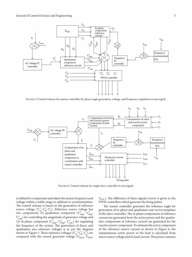
Figures 5 and 6 depict the block diagrams of the controlalgorithm employed for the proposed system. In this algo-rithm themaster controller is based on frequency and voltageregulation. The slave controller is based on active/reactivepower balance theory [12, 14, 15].
The proposed microgrid in islanded mode comprises onemaster DG which behaves as an ideal voltage source and oneslave DG which can be represented as ideal current source.Any voltage and frequency deviations are regulated by themaster controller.Therefore voltage and frequency controller
4 Journal of Control Science and Engineering
Hysteresis current controller
0
SEIG
a
bc
n
Reference current generation
i a
i n
ic
ib
VFC-BS
Lf, Rf
Lf, Rf
Lf, Rf
Lf, Rf
S1
S2
S3
S4
S5
S6
S7
S8
Vdc
Cdc
iLn
ILn
Hysteresis neutralcurrent controller
Small hydroturbine
Balanced/unbalanced/
consumer load
I∗sa I∗sb I
∗sc
I∗sn
IgaIgbIgc
iccn
i
i capa
i capb
capc I ca
I cb I c
c
iLaiLa
iLn
iLb
i Lb
iLc
iLc
Vo
+
−
−
+
−
Figure 2: The illustrative diagram of plant “1” with its entire control unit.
Master generator
PI controllerVgabc
abc
dq0
𝜃final
Vq +
+1/s
𝜃old
Δ𝜔
𝜔ref
Figure 3: Synchronizing scheme using DQ algorithm.
Unit/quadrature voltage generator of micro sourcesPI controller
U�a U�b U�c
Qa, Qb, Qc
𝜃final
𝜃old
+−newsin(𝜃)
Figure 4: Generation of unit vector using synchronizing angle (𝜃final).
Journal of Control Science and Engineering 5
Quadrature component reference current
In phase component referencecurrent
FrequencyPIcontroller
FrequencymeasurementPLL
*
PWM controller
+_
AC voltage PI controller
Vt
Vtreff−
−
+
+ +
+
Qa
Qb
Qc
Ua
Ub
Uc
VgaVgb
Vgc
V∗sa V∗
sb V∗sc
V∗ scpp
V∗ sbpp
V∗ sapp
V∗scqq
V∗sbqq
V∗saqq
𝜃final
V∗q
V∗d
Vabc
Freff
Figure 5: Control scheme for master controller for phase angle generation, voltage, and frequency regulation in microgrid.
Firing pulse
Computation of in-phase and quadrature component in coordination with master controller
Computation of active and reactive power component of load current
Computation of active and reactive power
component
FrequencyPIcontroller
measurementPLL
Hysteresis current controller
AC voltage PI controller
+
++
+
Vt
iq
id
i∗q
i∗d
i∗DGa
i∗DGb
i∗DGc
+ −
−
−
PL
QL
ILa ILb ILc
Va
Vb
Vc
Vabc
iDGa
iDGb
iDGc
VtreffFreff
Frequency
∗
Figure 6: Control scheme for single slave controller in microgrid.
is utilized to compensate and adjust the system frequency andvoltage within a stable range in addition to synchronization.The control scheme is based on the generation of referencesource voltage (𝑉∗
𝑠𝑎, 𝑉∗
𝑠𝑏, 𝑉∗
𝑠𝑐). Reference source voltage has
two components: (1) quadrature component (𝑉∗𝑠𝑎𝑞𝑞
, 𝑉∗𝑠𝑏𝑞𝑞
,𝑉∗
𝑠𝑐𝑞𝑞) for controlling the magnitude of generator voltage and
(2) in-phase component (𝑉∗𝑠𝑎𝑝𝑝
, 𝑉∗𝑠𝑏𝑝𝑝
, 𝑉∗𝑠𝑐𝑝𝑝
) for regulatingthe frequency of the system. The generation of direct andquadrature axis reference voltages is as per the diagramshown in Figure 5. These reference voltages (𝑉∗
𝑠𝑎, 𝑉∗
𝑠𝑏, 𝑉∗
𝑠𝑐) are
compared with the sensed generator voltage (𝑉DG𝑎, 𝑉DG𝑏,
𝑉DG𝑐). The difference of these signals (error) is given to thePWM controllers which generate the firing pulses.
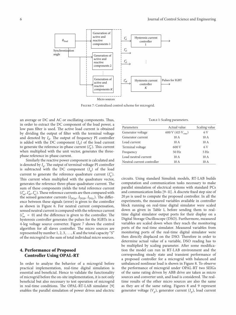
The master controller generates the reference angle forgeneration of in-phase and quadrature unit vector templatesof the slave controller. The in-phase components of referencecurrent are generated from the active power and the quadra-ture components of reference current are generated for thereactive power component. To estimate the active componentof the reference source current as shown in Figure 6, theinstantaneous active power of the load is calculated frommicro source voltage and its load current.This power contains
6 Journal of Control Science and Engineering
Synchronization angle
Generation of active and reactive components 1
Generation of active and reactive components K
Generation of active and reactive components 2
Hysteresis current controller
1
Hysteresis current controller
K
Pulses for IGBT
Micro sources
𝜃final
...
...
I∗s1
I∗s2
I∗s3
I∗sK
Figure 7: Centralized control scheme for microgrid.
an average or DC and AC or oscillating components. Thus,in order to extract the DC component of the load power, alow pass filter is used. The active load current is obtainedby dividing the output of filter with the terminal voltageand denoted by 𝐼𝑑. The output of frequency PI controlleris added with the DC component (𝐼𝑑) of the load currentto generate the reference in-phase current (𝐼∗
𝑑). This current
when multiplied with the unit vector, generates the three-phase reference in-phase current.
Similarly the reactive power component is calculated andis denoted by 𝐼𝑞. The output of terminal voltage PI controlleris subtracted with the DC component (𝐼𝑞) of the loadcurrent to generate the reference quadrature current (𝐼∗
𝑞).
This current when multiplied with the quadrature vector,generates the reference three-phase quadrature current. Thesum of these components yields the total reference current(𝐼∗𝑠𝑎, 𝐼∗𝑠𝑏, 𝐼∗𝑠𝑐).These reference currents are then comparedwith
the sensed generator currents (𝐼DG𝑎, 𝐼DG𝑏, 𝐼DG𝑐). The differ-ence between these signals (error) is given to the controlleras shown in Figure 6. For neutral current compensation,sensed neutral current is comparedwith the reference current(𝑖∗𝑠𝑛= 0) and the difference is given to the controller. The
hysteresis controller generates the pulses for the IGBTs in a4-leg voltage source converter. Figure 7 shows the controlalgorithm for all slaves controller. The micro sources arerepresented by number 1, 2, 3, . . . , 𝐾 and the total capacity “𝑆”of the microgrid is the sum of total individual micro sources.
4. Performance of ProposedController Using OPAL-RT
In order to analyze the behavior of a microgrid beforepractical implementation, real-time digital simulation isessential and beneficial. Hence to validate the functionalityof microgrid before the on-site implementation, it is not onlybeneficial but also necessary to test operation of microgridin real-time conditions. The OPAL-RT-LAB simulator [9]enables the parallel simulation of power drives and electric
Table 1: Scaling parameters.
Parameters Actual value Scaling valueGenerator voltage 600V (415Vrms) 6VGenerator current 10A 10ALoad current 10A 10ATerminal voltage 600V 6VFrequency 50Hz 5HzLoad neutral current 10A 10ANeutral current controller 10 A 10A
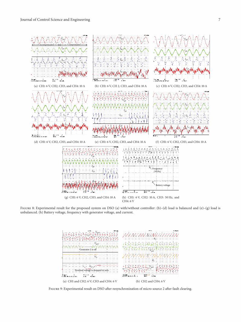
circuits. Using standard Simulink models, RT-LAB buildscomputation and communication tasks necessary to makeparallel simulation of electrical systems with standard PCsand communication links [9–11]. A discrete fixed step size of20𝜇s is used to compute the proposed controller. In all theexperiments, the measured variables available in controllerblock running on real-time digital simulator were scaleddown as given in Table 1, before sending them to real-time digital simulator output ports for their display on aDigital Storage Oscilloscope (DSO). Furthermore, measuredvariables are scaled down when they reach the monitoringports of the real-time simulator. Measured variables frommonitoring ports of the real-time digital simulator werethen directly displaced on the DSO. Therefore in order todetermine actual value of a variable, DSO reading has tobe multiplied by scaling parameter. After some modifica-tion the model can run in RT-LAB environment and thecorresponding steady state and transient performance ofa proposed controller for a microgrid with balanced andunbalanced nonlinear load is shown in Figure 8. To observethe performance of microgrid under OPAL-RT two SEIGsof the same rating driven by ABB drive are taken as microsources and converter unit, and load is considered. The real-time results of the other micro sources are also the sameas they are of the same rating. Figures 8 and 9 representgenerator voltage (𝑉𝑔), generator current (𝐼𝑔), load current
Journal of Control Science and Engineering 7
Uncompensated Compensated
Vga
Iga
ILa
Ica
(a) CH1: 6V, CH2, CH3, and CH4: 10 A
Vga
Iga
ILa
Ica
(b) CH1: 6V, CH 2, CH3, and CH4: 10 A
Vgb
Igb
ILb
Icb
(c) CH1: 6V, CH2, CH3, and CH4: 10 A
Vgc
Igc
ILc
Icc
(d) CH1: 6V, CH2, CH3, and CH4: 10 A
Vga
Iga
ILa
Ica
(e) CH1: 6V, CH2, CH3, and CH4: 10 A
Vgc
Igc
ILc
Icc
(f) CH1: 6V, CH2, CH3, and CH4: 10 A
Vgb
Igb
ILb
Icb
(g) CH1: 6V, CH2, CH3, and CH4: 10 A
Vga
Iga
Frequency(50Hz)
Battery voltage
(h) CH1: 6V, CH2: 10 A, CH3: 50Hz, andCH4: 6V
Figure 8: Experimental result for the proposed system on DSO (a) with/without controller: (b)–(d) load is balanced and (e)–(g) load isunbalanced. (h) Battery voltage, frequency with generator voltage, and current.
Vga1
Vga2
Vt2
Generator 2 is off
Terminal voltage is dropped to zero
Vt1
(a) CH1 and CH2: 6V; CH3 and CH4: 6V
𝜃1
Vga1
𝜃2
Vga3
(b) CH2 and CH4: 6V
Figure 9: Experimental result on DSO after resynchronization of micro source 2 after fault clearing.
8 Journal of Control Science and Engineering
(𝐼𝐿), controller current (𝐼𝑐), load neutral current (𝐼𝐿𝑛), andneutral current controller (𝐼𝐿𝑛𝑐).𝑉𝑔𝑎 represents the generatorvoltage of phase “𝑎” for both generators.
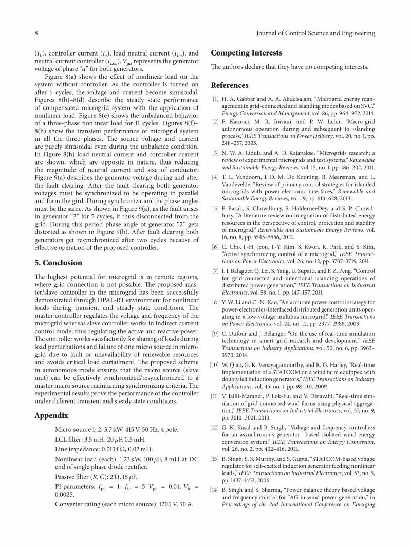
Figure 8(a) shows the effect of nonlinear load on thesystem without controller. As the controller is turned onafter 5 cycles, the voltage and current become sinusoidal.Figures 8(b)–8(d) describe the steady state performanceof compensated microgrid system with the application ofnonlinear load. Figure 8(e) shows the unbalanced behaviorof a three-phase nonlinear load for 11 cycles. Figures 8(f)–8(h) show the transient performance of microgrid systemin all the three phases. The source voltage and currentare purely sinusoidal even during the unbalance condition.In Figure 8(h) load neutral current and controller currentare shown, which are opposite in nature, thus reducingthe magnitude of neutral current and size of conductor.Figure 9(a) describes the generator voltage during and afterthe fault clearing. After the fault clearing both generatorvoltages must be synchronized to be operating in paralleland form the gird. During synchronization the phase anglesmust be the same. As shown in Figure 9(a), as the fault arisesin generator “2” for 5 cycles, it thus disconnected from thegrid. During this period phase angle of generator “2” getsdistorted as shown in Figure 9(b). After fault clearing bothgenerators get resynchronized after two cycles because ofeffective operation of the proposed controller.
5. Conclusion
The highest potential for microgrid is in remote regions,where grid connection is not possible. The proposed mas-ter/slave controller in the microgrid has been successfullydemonstrated through OPAL-RT environment for nonlinearloads during transient and steady state conditions. Themaster controller regulates the voltage and frequency of themicrogrid whereas slave controller works in indirect currentcontrol mode, thus regulating the active and reactive power.The controller works satisfactorily for sharing of loads duringload perturbations and failure of one micro source in micro-grid due to fault or unavailability of renewable resourcesand avoids critical load curtailment. The proposed schemein autonomous mode ensures that the micro source (slaveunit) can be effectively synchronized/resynchronized to amaster micro source maintaining synchronizing criteria. Theexperimental results prove the performance of the controllerunder different transient and steady state conditions.
Appendix
Micro source 1, 2: 3.7 kW, 415V, 50Hz, 4 pole.LCL filter: 3.5mH, 20 𝜇F, 0.5mH.Line impedance: 0.0134�, 0.02mH.Nonlinear load (each): 1.23 kW, 100𝜇F, 8mH at DCend of single phase diode rectifier.Passive filter (𝑅, 𝐶): 2�, 15 𝜇F.PI parameters: 𝑓pc = 1, 𝑓ic = 5, 𝑉pc = 0.01, 𝑉ic =0.0025.Converter rating (each micro source): 1200V, 50A.
Competing Interests
The authors declare that they have no competing interests.
References
[1] H. A. Gabbar and A. A. Abdelsalam, “Microgrid energy man-agement in grid-connected and islandingmodes based on SVC,”Energy Conversion andManagement, vol. 86, pp. 964–972, 2014.
[2] F. Katiraei, M. R. Iravani, and P. W. Lehn, “Micro-gridautonomous operation during and subsequent to islandingprocess,” IEEE Transactions on Power Delivery, vol. 20, no. 1, pp.248–257, 2005.
[3] N. W. A. Lidula and A. D. Rajapakse, “Microgrids research: areview of experimental microgrids and test systems,”Renewableand Sustainable Energy Reviews, vol. 15, no. 1, pp. 186–202, 2011.
[4] T. L. Vandoorn, J. D. M. De Kooning, B. Meersman, and L.Vandevelde, “Review of primary control strategies for islandedmicrogrids with power-electronic interfaces,” Renewable andSustainable Energy Reviews, vol. 19, pp. 613–628, 2013.
[5] P. Basak, S. Chowdhury, S. HalderneeDey, and S. P. Chowd-hury, “A literature review on integration of distributed energyresources in the perspective of control, protection and stabilityof microgrid,” Renewable and Sustainable Energy Reviews, vol.16, no. 8, pp. 5545–5556, 2012.
[6] C. Cho, J.-H. Jeon, J.-Y. Kim, S. Kwon, K. Park, and S. Kim,“Active synchronizing control of a microgrid,” IEEE Transac-tions on Power Electronics, vol. 26, no. 12, pp. 3707–3719, 2011.
[7] I. J. Balaguer, Q. Lei, S. Yang, U. Supatti, and F. Z. Peng, “Controlfor grid-connected and intentional islanding operations ofdistributed power generation,” IEEE Transactions on IndustrialElectronics, vol. 58, no. 1, pp. 147–157, 2011.
[8] Y. W. Li and C.-N. Kao, “An accurate power control strategy forpower-electronics-interfaced distributed generation units oper-ating in a low-voltage multibus microgrid,” IEEE Transactionson Power Electronics, vol. 24, no. 12, pp. 2977–2988, 2009.
[9] C. Dufour and J. Belanger, “On the use of real-time simulationtechnology in smart grid research and development,” IEEETransactions on Industry Applications, vol. 50, no. 6, pp. 3963–3970, 2014.
[10] W. Qiao, G. K. Venayagamoorthy, and R. G. Harley, “Real-timeimplementation of a STATCOM on a wind farm equipped withdoubly fed induction generators,” IEEETransactions on IndustryApplications, vol. 45, no. 1, pp. 98–107, 2009.
[11] V. Jalili-Marandi, P. Lok-Fu, and V. Dinavahi, “Real-time sim-ulation of grid-connected wind farms using physical aggrega-tion,” IEEE Transactions on Industrial Electronics, vol. 57, no. 9,pp. 3010–3021, 2010.
[12] G. K. Kasal and B. Singh, “Voltage and frequency controllersfor an asynchronous generator—based isolated wind energyconversion system,” IEEE Transactions on Energy Conversion,vol. 26, no. 2, pp. 402–416, 2011.
[13] B. Singh, S. S. Murthy, and S. Gupta, “STATCOM-based voltageregulator for self-excited induction generator feeding nonlinearloads,” IEEE Transactions on Industrial Electronics, vol. 53, no. 5,pp. 1437–1452, 2006.
[14] B. Singh and S. Sharma, “Power balance theory based voltageand frequency control for IAG in wind power generation,” inProceedings of the 2nd International Conference on Emerging

Journal of Control Science and Engineering 9
Trends in Engineering and Technology (ICETET ’09), pp. 40–45,IEEE, Nagpur, India, December 2009.
[15] V. Verma and G. G. Talpur, “Decentralized Master-Slaveoperation of microgrid using current controlled distributedgeneration sources,” in Proceedings of the IEEE InternationalConference on Power Electronics, Drives and Energy Systems(PEDES ’12), pp. 1–6, Bengaluru, India, December 2012.

International Journal of
AerospaceEngineeringHindawi Publishing Corporationhttp://www.hindawi.com Volume 2014
RoboticsJournal of
Hindawi Publishing Corporationhttp://www.hindawi.com Volume 2014
Hindawi Publishing Corporationhttp://www.hindawi.com Volume 2014
Active and Passive Electronic Components
Control Scienceand Engineering
Journal of
Hindawi Publishing Corporationhttp://www.hindawi.com Volume 2014
International Journal of
RotatingMachinery
Hindawi Publishing Corporationhttp://www.hindawi.com Volume 2014
Hindawi Publishing Corporation http://www.hindawi.com
Journal ofEngineeringVolume 2014
Submit your manuscripts athttp://www.hindawi.com
VLSI Design
Hindawi Publishing Corporationhttp://www.hindawi.com Volume 2014
Hindawi Publishing Corporationhttp://www.hindawi.com Volume 2014
Shock and Vibration
Hindawi Publishing Corporationhttp://www.hindawi.com Volume 2014
Civil EngineeringAdvances in
Acoustics and VibrationAdvances in
Hindawi Publishing Corporationhttp://www.hindawi.com Volume 2014
Hindawi Publishing Corporationhttp://www.hindawi.com Volume 2014
Electrical and Computer Engineering
Journal of
Advances inOptoElectronics
Hindawi Publishing Corporation http://www.hindawi.com
Volume 2014
The Scientific World JournalHindawi Publishing Corporation http://www.hindawi.com Volume 2014
SensorsJournal of
Hindawi Publishing Corporationhttp://www.hindawi.com Volume 2014
Modelling & Simulation in EngineeringHindawi Publishing Corporation http://www.hindawi.com Volume 2014
Hindawi Publishing Corporationhttp://www.hindawi.com Volume 2014
Chemical EngineeringInternational Journal of Antennas and
Propagation
International Journal of
Hindawi Publishing Corporationhttp://www.hindawi.com Volume 2014
Hindawi Publishing Corporationhttp://www.hindawi.com Volume 2014
Navigation and Observation
International Journal of
Hindawi Publishing Corporationhttp://www.hindawi.com Volume 2014
DistributedSensor Networks
International Journal of