Embed Size (px)
Citation preview

Hindawi Publishing CorporationInternational Journal of Antennas and PropagationVolume 2013 Article ID 516946 12 pageshttpdxdoiorg1011552013516946
Research ArticleScattering Analysis of a Compact Dipole Array with Series andParallel Feed Network including Mutual Coupling Effect
H L Sneha Hema Singh and R M Jha
Computational Electromagnetics Laboratory CSIR-National Aerospace Laboratories Bangalore 560017 India
Correspondence should be addressed to Hema Singh ishihema30gmailcom
Received 28 January 2013 Revised 30 April 2013 Accepted 7 May 2013
Academic Editor Hon Tat Hui
Copyright copy 2013 H L Sneha et al This is an open access article distributed under the Creative Commons Attribution Licensewhich permits unrestricted use distribution and reproduction in any medium provided the original work is properly cited
The current focus in defense arena is towards the stealth technology with an emphasis to control the radar cross-section (RCS)The scattering from the antennas mounted over the platform is of prime importance especially for a low-observable aerospacevehicle This paper presents the analysis of the scattering cross section of a uniformly spaced linear dipole array Two types of feednetworks that is series and parallel feed networks are consideredThe total RCS of phased array with either kind of feed network isobtained by following the signal as it enters through the aperture and travels through the feed networkThe RCS estimation of arrayis done including the mutual coupling effect between the dipole elements in three configurations that is side-by-side collinearand parallel-in-echelon The results presented can be useful while designing a phased array with optimum performance towardslow observability
1 Introduction
The radar cross-section (RCS) is essentially a measure ofelectric field scattered from an object towards the radar [1] Aphased array antenna system mounted on the target scattersthe incident signals contributing significantly towards thetotal RCS of the target The antenna scattering is function ofparameters like antenna type [2] array configuration and thenature of feed network In addition the presence of mutualcoupling in between the antenna elements plays an importantrole in overall RCSThe emerging stealth technologies aim atreducing the scattering from an object to the least possibleextent in order to shield it from the enemy radars Howeverlow observable platform has consequence of sacrificing arrayperformance in terms of gain and radiation characteristics[3]
In the open domain several techniques have been pro-posed for the estimation of the antenna RCS These includenumerical techniques [4] as well as high-frequency tech-niques [5] along with the optimization [6] Most of theapproaches neglect the presence of mutual coupling edgeeffects and the higher order reflections
Most of the proposed methods focus on the compen-sation of mutual coupling in receiving arrays [7 8] andthe array feed network [9ndash12] The behavior of antennaarrays in receiving and transmitting modes needs not besame The factors like different signal paths within thetransmitting and receiving array system anddifferent antennaexcitations in the two systems make the mutual couplingeffect different in the two modes [13] The techniques ofestimating the mutual impedance for transmitting arrayslike conventional impedance matrix method [14] differ fromthose for receiving array The techniques to calculate thereceiving mode impedance include full-wave methods [1516] the calibration methods [17 18] and the receiving-mutual impedance method (RMIM) [19ndash21] The efficiencyand accuracy of receiving mutual impedances is furtherimproved by preserving the original boundary conditionsof the compact array during the analysis [22] Niow et al[23] suggested the method for the compensation of mutualcoupling in transmitting arrays The compensation networkdesigned in terms of mutual impedances is employed topredict the radiation pattern using the principle of patternmultiplication This approach facilitates the port decoupling
2 International Journal of Antennas and Propagation
middot middot middot
middot middot middot middot middotmiddot
Zl1(1198732)
21
Reference element
Delay line modeling of
phase-shifters
Dipole
Coupler
Terminating load
Receive port
119873119873minus 1
11988511988611198851198862
119885119886119873minus1119885119886119873
11988511990111198851199012
119885119901119873minus1119885119901119873
11988511988811198851198882
11988511989711
119885119888119873minus1119885119888119873
1198851198971199021 1198850
1198711 1198712 119871119873minus1 119871119873
Figure 1 Typical parallel-feed network of dipole phased array
and design ofmatching circuits towards themaximumpowertransfer Wang and Hui [24] proposed a system identificationmethod for the wideband mutual coupling compensationof receiving arrays A multiport compensation network isobtained based on the receiving mutual impedances of anantenna array over the frequency band
The effect of feed network on the RCS of the phased arrayhas been analyzed [9 10] using analytical technique of tracingthe signal path through the antenna system However theproposed method considered an array of identical isotropicelements The mutual coupling edge effects and the higherorder reflectionswere not taken into account In this paper anattempt is made to analyze the antenna mode scattering of alinear series-fed [25] and parallel-fed dipole array (Figure 1)considering the mutual coupling effect The variation in thearray configuration (side-by-side collinear and parallel-in-echelon) and the type of amplitude distribution (uniformunitamplitude Taylor cosine-squared on a pedestal and Dolph-Chebyshev) are studied The RCS formulation involves thetracing of the signal path from the antenna aperture intothe antenna system for estimation of the scattered field ateach component level The individual contributions towardsthe scattered field are expressed in terms of the reflectionand transmission coefficients of components in the antennasystem These scattered fields at each level of antenna systemare then coherently summed up to arrive at the total antennaarray RCS
Section 2 presents a brief analysis on the RCS formulationof linear dipole arrays with different feed network in the pres-ence of mutual coupling The simulation results comparingthe RCS of dipole array with and without mutual couplingare discussed in Section 3 The role of the optimum load inthe feed network in RCS estimation is analyzed
2 RCS Formulation for a Linear Dipole Array
The RCS of an object for a plane wave incidence can beexpressed as the ratio of the scattered field to the incidentfield The antenna mode scattered field is expressed as [26]
119864
119904
119899(120579 120601) = [
119895120578
4120582119885119886
ℎ
ℎ sdot
119864
119894
(120579 120601)
119890
minus119895119896
119877
]Γ
119903
119899(120579 120601) (1)
where 119864
119904
119899is the scattered field at the 119899th element
119864
119894 isthe incident field (120579 120601) is the direction of signal 119885
119886is the
radiation impedance 120582 is the wavelength 120578 is the impedanceof medium surrounding the antenna
119896 is the wave vector 119877is the distance between the target and the observation pointΓ
119903
119899is the total reflected signal returning to aperture element
119899 and ℎ is the effective height of the antenna element For a
International Journal of Antennas and Propagation 3
Dipole element5 10 15 20 25 30
125
150
175
200
225
250
275
300
325
350
375
Uniform unit amplitudeCosine squared on a pedestal
Dolph-ChebyshevTaylor
Dip
ole r
esist
ance
(Ω)
(a) Resistance
Uniform unit amplitudeCosine squared on a pedestal
Dolph-ChebyshevTaylor
Dipole element5 10 15 20 25 30
Dip
ole r
esist
ance
(Ω)
minus170
minus160
minus150
minus140
minus130
minus120
minus110
minus100
minus90
minus80
minus70
minus60
minus50
minus40
(b) Reactance
Figure 2 Terminal impedance 119885119886119899
of the dipole elements in side-by-side configuration
unit amplitude plane wave impinging on the array of lossless119909-polarized dipoles placed in free space (1) becomes
119864
119904
119899(120579 120601) = [
119895120578119900
4120582119885119886
ℎ
2
(119909 sdot120579) 119890
minus119895119896sdot119889119899
119890
minus119895119896
119877
]Γ
119903
119899(120579 120601) 119909 (2)
where 1205780is the free space impedance and
119889119899is the distance
vector Assuming a uniform dipole array with interelementspacing 119889 along 119909-axis the total scattered field is given by
119873
sum
119899=1
119864
119904
119899(120579 120601) =
119873
sum
119899=1
119895120578119900
4120582119885119886
ℎ
2 cos 120579Γ119903119899(120579 120601) 119890
119895(119899minus1)120572119890
minus119895119896
119877
119909
(3)
where 120572 = 119896119889 sin 120579 cos120601 represents the interelement spacedelay of the wave incident along 119909-direction 119896 is the wavenumber
The total RCS of the array expressed in terms of (3) is
120590 (120579 120601) = lim119877rarrinfin
4120587119877
2
1003816
1003816
1003816
1003816
1003816
sum
119873
119899=1
119864
119904
119899(120579 120601)
1003816
1003816
1003816
1003816
1003816
2
1003816
1003816
1003816
1003816
1003816
119864
119894(120579 120601)
1003816
1003816
1003816
1003816
1003816
2
= 4120587
1003816
1003816
1003816
1003816
1003816
1003816
1003816
1003816
1003816
1003816
119873
sum
119899=1
119895120578119900
4120582119885119886
ℎ
2 cos 120579 119864
119903
119899(120579 120601)
1003816
1003816
1003816
1003816
1003816
1003816
1003816
1003816
1003816
1003816
2
(4)
where 119864
119903
119899(120579 120601) = Γ
119903
119899(120579 120601)119890
119895(119899minus1)120572 represents the total scatteredfield returning to the aperture This can be expressed asthe summation of individual scattering sources of the feednetwork by navigating through the signal as it moves towardsthe receive port
In general a typical feed network will comprise ofantenna elements phase-shifters couplers and the termi-nating loads [27] Although an efficient receiver is intended
to receive the entire power incident on it certain amountof signal will be lost due to scattering within the antennasystem at components level before reaching the receiveport This scattered field is determined by the magnitude ofreflection and transmission coefficients at different levels offeed network which are due to the impedance mismatchesprevailing at their junctionsHowever it is to be noted that theexpressions presented in this paper assume reciprocal feednetwork components and neglect the effect of higher orderscattering
The first level of mismatch experienced by the incomingsignal will be at the junction of dipole terminals and thephase-shifters At this level the reflection coefficient of dipoleelement is given by [25]
119903119903119899
=
1003816
1003816
1003816
1003816
1003816
1003816
1003816
1003816
1003816
119885119886119899
minus 1198850
119885119886119899
+ 1198850
1003816
1003816
1003816
1003816
1003816
1003816
1003816
1003816
1003816
(5)
where 119903119903119899
is the reflection coefficient of the 119899th dipole 119885119886119899
is the terminal impedance of the 119899th dipole and 1198850is the
characteristic impedance of the delay line modeled phase-shifter
The terminal impedance of the dipoles is function of bothamplitude distribution and the array configuration [26] Fig-ures 2 3 and 4 indicate the variation of the impedance at theterminals of dipoles for different combinations of feed currentand the array geometry The choice of array configurationcontrols the antenna impedance that will further have animpact on the scattered field and RCS due to radiators thatis
119864
119903
119903119899
(120579 120601) = 119903119903119899
119890
1198952(119899minus1)120572
120590119903(120579 120601) =
1003816
1003816
1003816
1003816
1003816
1003816
1003816
1003816
1003816
1003816
119873
sum
119899=1
119895120578119900
4120582119885119886
ℎ
2 cos 120579 (119903119903119899
119890
1198952(119899minus1)120572
)
1003816
1003816
1003816
1003816
1003816
1003816
1003816
1003816
1003816
1003816
2
(6)
4 International Journal of Antennas and Propagation
110
115
120
125
130
135
Dipole element5 10 15 20 25 30
Uniform unit amplitudeCosine squared on a pedestal
Dolph-ChebyshevTaylor
Dip
ole r
esist
ance
(Ω)
(a) Resistance
35
355
36
365
37
375
38
385
39
395
40
Dipole element5 10 15 20 25 30
Uniform unit amplitudeCosine squared on a pedestal
Dolph-ChebyshevTaylor
Dip
ole r
esist
ance
(Ω)
(b) Reactance
Figure 3 Terminal impedance 119885119886119899
of the dipole elements in collinear configuration
160
180
200
220
240
260
Dipole element5 10 15 20 25 30
Uniform unit amplitudeCosine squared on a pedestal
Dolph-ChebyshevTaylor
Dip
ole r
esist
ance
(Ω)
(a) Resistance
55
60
65
70
75
80
85
90
95
100
Dipole element5 10 15 20 25 30
Uniform unit amplitudeCosine squared on a pedestal
Dolph-ChebyshevTaylor
Dip
ole r
esist
ance
(Ω)
(b) Reactance
Figure 4 Terminal impedance 119885119886119899
of the dipole elements in parallel-in-echelon configuration
Following a similar analysis one gets the scattered field andthe RCS due to the mismatch at the phase-shifters
119864
119903
119901119899
(120579 120601) = 119905
2
119903119899
119903119901119899
119890
1198952(119899minus1)120572
119903119901119899
=
1003816
1003816
1003816
1003816
1003816
1003816
1003816
1003816
1003816
119885119901119899
minus 1198850
119885119901119899
+ 1198850
1003816
1003816
1003816
1003816
1003816
1003816
1003816
1003816
1003816
120590119901(120579 120601) =
1003816
1003816
1003816
1003816
1003816
1003816
1003816
1003816
1003816
1003816
119873
sum
119899=1
119895120578119900
4120582119885119886
ℎ
2 cos 120579 (1199052119903119899
119903119901119899
119890
1198952(119899minus1)120572
)
1003816
1003816
1003816
1003816
1003816
1003816
1003816
1003816
1003816
1003816
2
(7)
where 119903119901119899
is the reflection coefficient at the phase-shifters 119905119903119899
is the transmission coefficient of the radiating elements and
119885119901119899
is the translated dipole terminal impedance as viewedat the end of phase-shifters Further the signal might sufferfrom reflection due to the differing impedances of phase-shifter terminals and the coupler ports The scattering at thislevel is determined by the nature of couplers and is thusspecific to the type of feed network exciting the dipoles
21 Dipole Array with Series Feed Network In this paperthe dipole elements in the series-fed linear phased array areexcited using lossless four-port couplers (Figure 5) Port 1 andPort 2 of each coupler are taken as a part of the main feedline while Port 3 and Port 4 are connected to the dipoles via
International Journal of Antennas and Propagation 5
Main feed line Main feed line
Port 1
Port 2
Port 3
Dipole via phase-shifter
Terminating impedance
Port 4
Figure 5 Schematic of a four-port coupler of the series feed networkin phased array
phase-shifters and the terminating load respectively FurtherPort 1 of the first element of the array acts as the receivingport while Port 2 of the last element is terminated with amatched load As a result Port 1 and Port 2 serve as input andoutput while Port 3 and Port 4 possess coupling and isolatingcharacteristics Moreover Ports (1 4) and (2 3) constituteisolated port pairs
The coupling and the transmission coefficients of thecoupler ports 119895119888
119899and 119905119888119899
in the presence of mutual couplingare given by [25]
119888119899=
119885119886119899
119894
2
119899
sum
119873
119901=1119885119886119901
119894
2
119901minus sum
119899minus1
119902=1119885119886119902
119894
2
119902
(8a)
119905
2
119888119899
= 1 minus 119888
2
119899 (8b)
where 119894119899is the current at the feed terminals of the 119899th antenna
elementEquations (8a) and (8b) indicate that the values of
coupling and transmission coefficients depend on the ter-minal impedance of dipoles and the type of the amplitudedistribution
In otherwords the coupling coefficients of the couplers inthe feed network are function of both amplitude distributionand array configuration (Figures 6 7 and 8)
In general the scattered field and the RCS of 119899th dipoleelement due to the mismatch at the coupling port of couplersare expressed as
119864
119903
119888119899
(120579 120601) = 119905
2
119903119899
119905
2
119901119899
119903119888119899
119890
1198952(119899minus1)(120572+120572119904)
120590119888(120579 120601) =
1003816
1003816
1003816
1003816
1003816
1003816
1003816
1003816
1003816
1003816
119873
sum
119899=1
119895120578119900
4120582119885119886
ℎ
2 cos 120579 (1199052119903119899
119905
2
119901119899
119903119888119899
119890
1198952(119899minus1)(120572+120572119904)
)
1003816
1003816
1003816
1003816
1003816
1003816
1003816
1003816
1003816
1003816
2
(9)
where 119903119888119899
= |(119885119888119899
minus119885119901119899
)(119885119888119899
+119885119901119899
)| is the reflection coefficientat the couplers 119885
119888119899
is the impedance at the coupling port of
Dipole element2 4 6 8 10 12 14 16 18 20 22 24 26 28 30
Cou
plin
g co
effici
ents
(mag
)
0
01
02
03
04
05
06
07
08
09
1
UniformCosine squared on pedestal
Dolph-ChebyshevTaylor
Figure 6 Coupling coefficients for different amplitude distributionsin a series-fed linear dipole array side-by-side configuration 119889 =
01 120582
the couplers 120572119904= 119896119889 sin 120579
119904cos120601119904is the interelement phase to
scan the antenna beam along 119909-axis at (120579119904 120601119904) and 119905
119901119899
is thetransmission coefficient of the phase-shifters
Beyond coupling port of the coupler in series feednetwork there can be several possible paths for the signal totravel further into the antenna system It can either (i) movetowards the previous element andor next element andor itsown (self) terminating load andor (ii) retrace its own pathThe scattered fields corresponding to each of the signal pathsare given by [23]
119864
119903
1119899
(120579 120601) = [119905119903119899
119905119901119899
119903119897119899
119895119888119899119890
119895(119899minus1)(120572+120572119904)
times
119873
sum
119898=119899+1
(119905119903119898
119905119901119898
119895119888119898119890
119895(119898minus1)120577
119898minus1
prod
119894=119899
119905119888119894
119890
119895120595
)]
119864
119903
2119899
(120579 120601) = [119905119903119899
119905119901119899
119895119888119899119890
119895(119899minus1)(120572+120572119904)
times
119899minus1
sum
119898=1
119905119903119898
119905119901119898
119903119897119898
119895119888119898119890
119895(119898minus1)120577
119899minus1
prod
119894=119898
119905119888119894
119890
119895120595
]
119864
119903
3119899
(120579 120601) = 119903119897119899
119905
2
119903119899
119905
2
119901119899
119905
2
119888119899
119890
1198952(119899minus1)(120572+120572119904)
119864
119903
4119899
(120579 120601) =[
[
119903119894119899119905
2
119903119899
119905
2
119901119899
(119895119888119899)
2
119890
1198952(119899minus1)(120572+120572119904)
(
119899minus1
prod
119894=1
119905119888119894
119890
119895120595
)
2
]
]
(10)
where 119903119897119899
is the reflection coefficient at 119899th element terminatedby a load impedance of119885
119897119899
and 119903119894119899is the reflection coefficient
6 International Journal of Antennas and Propagation
Dipole element2 4 6 8 10 12 14 16 18 20 22 24 26 28 30
Cou
plin
g co
effici
ents
(mag
)
0
01
02
03
04
05
06
07
08
09
1
UniformCosine squared on pedestal
Dolph-ChebyshevTaylor
Figure 7 Coupling coefficients for different amplitude distributionsin a series-fed linear dipole array collinear configuration 119889 = 01 120582
at the receive port connected to a coaxial cable of impedance1198850 Equation (10) signifies the importance of choosing appro-
priate value for the impedance terminating the coupler portsin the network From this the RCS due to the signal scatteringbeyond the coupling port of couplers becomes
120590119904(120579 120601)
=
1003816
1003816
1003816
1003816
1003816
1003816
1003816
1003816
1003816
1003816
119873
sum
119899=1
119895120578119900
4120582119885119886
ℎ
2 cos 120579 ( 119864
119903
1119899
(120579 120601) +
119864
119903
2119899
(120579 120601)
+
119864
119903
3119899
(120579 120601) +
119864
119903
4119899
(120579 120601))
1003816
1003816
1003816
1003816
1003816
1003816
1003816
1003816
1003816
1003816
2
(11)
Thus the total normalized RCS of the dipole array in thepresence of mutual coupling due to mismatches within theseries-feed network is given by
120590 (120579 120601) =
4120587
120582
2120590119903(120579 120601) + 120590
119901(120579 120601) + 120590
119888(120579 120601) + 120590
119904(120579 120601)
(12)
22 Parallel Feed Network In a phased array with parallelfeed network (Figure 9) the two input arms (Port 2 and Port3) of a first level coupler are connected to two different ele-ments and thus receive two different signals unlike the seriesfeed network (Figure 9(a)) Amongst the other two portsone acts as the sum port (Port 1) and the other as differenceport (Port 4) Having intention of receiving maximum signalpower the difference ports are load terminated while the sumports are connected to the input arms of the couplers in thefurther levels of the feed network
Dipole element2 4 6 8 10 12 14 16 18 20 22 24 26 28 30
Cou
plin
g co
effici
ents
(mag
)
0
01
02
03
04
05
06
07
08
09
1
UniformCosine squared on pedestal
Dolph-ChebyshevTaylor
Figure 8 Coupling coefficients for different amplitude distributionsin a series-fed linear dipole array parallel-in-echelon configuration119889 = 01 120582
In parallel-fed dipole array the reflection coefficients atthe input arms of the first-level couplers differ for the evenand odd elements of the array Mathematically
119903119888119899
=
1003816
1003816
1003816
1003816
1003816
1003816
1003816
1003816
1003816
119885331119894
minus 119885119901119899
119885331119894
+ 119885119901119899
1003816
1003816
1003816
1003816
1003816
1003816
1003816
1003816
1003816
for odd-numbered elements
119903119888119899
=
1003816
1003816
1003816
1003816
1003816
1003816
1003816
1003816
1003816
119885221119894
minus 119885119901119899
119885221119894
+ 119885119901119899
1003816
1003816
1003816
1003816
1003816
1003816
1003816
1003816
1003816
for even-numbered elements
(13)
where 119894 = 1 2 (119873+1)2 is an integer and 119899 = 1 2 119873The index 119894 increments at each odd element of the dipole
array that is
1199031198881
=
1003816
1003816
1003816
1003816
1003816
1003816
1003816
1003816
1003816
1198853311
minus 1198851199011
1198853311
+ 1198851199011
1003816
1003816
1003816
1003816
1003816
1003816
1003816
1003816
1003816
1199031198882
=
1003816
1003816
1003816
1003816
1003816
1003816
1003816
1003816
1003816
1198852211
minus 1198851199012
1198852211
+ 1198851199012
1003816
1003816
1003816
1003816
1003816
1003816
1003816
1003816
1003816
1199031198883
=
1003816
1003816
1003816
1003816
1003816
1003816
1003816
1003816
1003816
1198853312
minus 1198851199013
1198853312
+ 1198851199013
1003816
1003816
1003816
1003816
1003816
1003816
1003816
1003816
1003816
(14)
This yields the RCS contribution from the input ports ofthe first level couplers similar to that of series feed networkOne can observe that the signal incident at the antennapasses through phase shifters and reaches the couplers The
International Journal of Antennas and Propagation 7
21
Coupler 1 Coupler 2
Port 3
Port 2
Port 4
Port 1
(a)
1 2
Coupler 1
Port 4 Port 1
Port 2Port 3
(b)
Figure 9 The arrangement of couplers (a) Series feed network (b) Parallel feed network
signal which manages to pass through the input arms ofthe couplers would either move towards the sum or thedifference port At these points significant reflection canoccur due to the mismatch of impedances indicated by thefactors 119903
119904119902119894
and 119903119889119902119894
for sum and difference ports respectively(Figure 10) Here subsuffices 119902 and 119894 indicate the coupler-leveland the coupler number The magnitude of these reflectioncoefficients depends on both the position of dipole elementin the array and the corresponding impedances
221 First Level Couplers Assuming all higher levels of cou-plers in the feed network except for the first to be perfectlymatched the scattered field can be calculated only for the firstlevel of couplers Hence the characteristic impedance (119885
0) at
the receive port will appear at the sum ports of all first levelcouplersThe scattered field due to first level couplers at odd-numbered elements owing to the signal reflections at sumand difference ports obtained by following the path of thesignal (Figure 11) is
119864
119903
119899odd(120579 120601) = 119905
119903119899
119905119901119899
119890
119895(119899minus1)(120572+120572119904)[
[
119903119904(1198992+1)
119888(1198992+1)
119890
119895120595
119905119903119899
119905119901119899
119890
119895(119899minus1)(120572+120572119904)
119888(1198992+1)
119890
119895120595
+ 119905119903119899+1
119905119901119899+1
119890
119895(119899)(120572+120572119904)
119905119888(1198992+1)
+119903119889(1198992+1)
119905119888(1198992+1)
119905119903119899
119905119901119899
119890
119895(119899minus1)(120572+120572119904)
119905119888(1198992+1)
+ 119905119903119899+1
119905119901119899+1
119890
119895(119899)(120572+120572119904)
119888(1198992+1)
119890
119895120595
]
]
(15)
Here the expressions for the sum and difference port reflec-tion coefficients are given by
1199031199041(1198992+1)
=
1003816
1003816
1003816
1003816
1003816
1003816
1003816
1003816
1003816
1003816
119885111(1198992+1)
minus 119885131(1198992+1)
119885111(1198992+1)
+ 119885131(1198992+1)
1003816
1003816
1003816
1003816
1003816
1003816
1003816
1003816
1003816
1003816
1199031198891(1198992+1)
=
1003816
1003816
1003816
1003816
1003816
1003816
1003816
1003816
1003816
1003816
119885441(1198992+1)
minus 119885331(1198992+1)
119885441(1198992+1)
+ 119885331(1198992+1)
1003816
1003816
1003816
1003816
1003816
1003816
1003816
1003816
1003816
1003816
(16)
where 1198851198981198981015840
119902119894
indicate the impedance at Port 119898 and Port 1198981015840
of 119894th coupler in 119902th level of feed networkThe factor (1198992) inthe previous equations is integer
Similar analogy for even-numbered elements (Figure 12)yields
119864
119903
119899even(120579 120601) = 119905
119903119899
119905119901119899
119890
119895(119899minus1)(120572+120572119904)
[
119903119904(1198992)
119905119888(1198992)
119905119903119899minus1
119905119901119899minus1
119890
119895(119899minus2)(120572+120572119904)
119888(1198992)
119890
119895120595
+ 119905119903119899
119905119901119899
119890
119895(119899minus1)(120572+120572119904)
119905119888(1198992)
+119903119889(1198992)
119888(1198992)
119890
119895120595
119905119903119899minus1
119905119901119899minus1
119890
119895(119899minus2)(120572+120572119904)
119905119888(1198992)
+ 119905119903119899
119905119901119899
119890
119895(119899minus1)(120572+120572119904)
119888(1198992)
119890
119895120595
] (17)
where
1199031198891(1198992)
=
1003816
1003816
1003816
1003816
1003816
1003816
1003816
1003816
1003816
1003816
119885441(1198992)
minus 119885421(1198992)
119885441(1198992)
+ 119885421(1198992)
1003816
1003816
1003816
1003816
1003816
1003816
1003816
1003816
1003816
1003816
(18)
1199031199041(1198992)
=
1003816
1003816
1003816
1003816
1003816
1003816
1003816
1003816
1003816
1003816
119885221(1198992)
minus 119885111(1198992)
119885221(1198992)
+ 119885111(1198992)
1003816
1003816
1003816
1003816
1003816
1003816
1003816
1003816
1003816
1003816
for even-numbered elements
(19)
Thus the RCS corresponding to the odd and even dipoleelements in the array due to reflections at sum and differenceports of couplers is given by
120590odd (120579 120601) =
1003816
1003816
1003816
1003816
1003816
1003816
1003816
1003816
1003816
1003816
119873
sum
119899=odd
119895120578119900
4120582119885119886
ℎ
2 cos 120579 119864
119903
119899odd(120579 120601)
1003816
1003816
1003816
1003816
1003816
1003816
1003816
1003816
1003816
1003816
2
120590even (120579 120601) =
1003816
1003816
1003816
1003816
1003816
1003816
1003816
1003816
1003816
1003816
119873
sum
119899=even
119895120578119900
4120582119885119886
ℎ
2 cos 120579 119864
119903
119899even(120579 120601)
1003816
1003816
1003816
1003816
1003816
1003816
1003816
1003816
1003816
1003816
2
(20)
8 International Journal of Antennas and Propagation
Antenna element 2
Antenna element 1
Terminating load
Receive port
Antenna element 1
Phase-shifter
Phase-shifter
Phase-shifter
Coupler levels
1199031199031 1199031199032 119903119903119899
1199031199011 1199031199012 119903119901119899
1199031198881 1199031198882
119903119889119902119894 119903119904119902119894
middot middot middot
rc119873
Figure 10 Reflection coefficients at different levels of the parallelfeed network
Incident signal Scattered field
Load
119890119895(119899minus1)120572 119890119895(119899minus1)120572
119899 119899 + 1
119890119895119899120572
119905119903119899119905119903119899 119905119903119899+1
119905119901119899 119890119895(119899minus1)120572119904119905119901119899 119890
119895(119899minus1)120572119904 119905119901119899+1 119890119895119899120572119904
119905119888119894119905119888119894119905119888119894 119888119894
119888119894119888119894
119890119895120595
119890119895120595
119903119889119894119903119904119894
Figure 11 Signal paths through the first-level couplers in theparallel-feed network of a linear dipole array for 119899th odd-numberedelement
Thus the normalized overall RCS of a parallel-fed lineardipole array considering the scattering up to first levelcouplers is expressed as
120590 (120579 120601) =
4120587
120582
2120590119903(120579 120601) + 120590
119901(120579 120601) + 120590
119888(120579 120601)
+120590odd (120579 120601) + 120590even (120579 120601)
(21)
3 Results and Discussion
In this paper scattering from a linear dipole array fed byseries and parallel feed network is calculated The softwarecode is developed in Fortran 90 based on the formulationdiscussed in Section 2 The RCS patterns are shown inplotting subroutine Sigmaplot v10 The results are presentedfor bothwith andwithoutmutual coupling effectThe currentover the surface of each individual wire-type half wavelengthdipole array is assumed to be a cosine function
Incident signalScattered field
Load
119890119895(119899minus2)120572 119890119895(119899minus1)120572119890119895(119899minus1)120572
119899
119905119903119899119905119903119899
119905119901119899 119890119895(119899minus1)120572119904 119905119901119899 119890
119895(119899minus1)120572119904
119905119888119894119905119888119894
119905119888119894119888119894
119888119894
119903119889119894119903119904119894
n minus 1
tr119899minus1
tp119899minus1 ej(nminus2)120572119904
Figure 12 Signal paths through the first-level couplers in theparallel-feed network of a linear dipole array for 119899th even-numberedelement
Angle (deg)0 20 40 60 80
Nor
mal
ized
RCS
(dB) 0
10
20
Without mutual couplingWith mutual coupling
minus80 minus60 minus40 minus20minus50
minus40
minus30
minus20
minus10
Figure 13 RCS of a parallel-in-echelon series-fed linear dipole array(119873 = 40) with Dolph-Chebyshev amplitude distribution (120579
119904= 0
∘)
Figure 13 shows the broadside (at 0∘) RCS of a series-fed parallel-in-echelon 40-element dipole array terminatedby the load of 130Ω The receive port of the array system isconnected to 100Ω coaxial cable The amplitude distributionat the dipole feed terminals is taken to be Dolph-ChebyshevThe interelement spacing is taken as 02 120582 It can be seen thatin the RCS pattern the specular lobe (lobe at 0∘) remainsthe same for both with and without mutual coupling casesHowever a noticeable variation in the sidelobe location andlevels is evident The adverse effect of coupling on RCSpattern worsens as the array scan angle is increased from 0∘to 65∘ keeping all other parameters unchanged (Figure 14)
International Journal of Antennas and Propagation 9
Angle (deg)0 20 40 60 80
Nor
mal
ized
RCS
(dB) 0
10
20
Without mutual couplingWith mutual coupling
minus80 minus60 minus40 minus20minus50
minus40
minus30
minus20
minus10
Figure 14 RCS of a series-fed parallel-in-echelon linear dipole array(119873 = 40) with Doplh-Chebyshev amplitude distribution (120579
119904= 65
∘)
Angle (deg)0 20 40 60 80
Nor
mal
ized
RCS
(dB) 0
10
20
Without mutual couplingWith mutual coupling
minus80 minus60 minus40 minus20minus50
minus40
minus30
minus20
minus10
Figure 15 Broadside RCS of a series-fed 40-element linear dipolearray in side-by-side configuration with Taylor amplitude distribu-tion (120579
120590= 0
∘)
The observed phenomenon signifies the dependence ofmutual coupling effect on the array scan angle [28]
Figures 15 and 16 exhibit a similar trend for 40-elementlinear dipole array in side-by-side configuration with Tayloramplitude distribution when terminated with 200Ω Resultsare compared for with and without mutual coupling cases
The variation in the broadside RCS of a 32-elementparallel-fed linear dipole array with an interelement spacingof 04 120582 in the presence of mutual coupling is shown inFigure 17 Here all the couplers in the feed network areassumed to be equal power combiners (receive array) and thecoupling and transmission coefficients are taken be 1radic2Thedipole elements are arranged in side-by-side configurationwith 20Ω load termination at the difference arms of the first
Angle (deg)0 20 40 60 80
Nor
mal
ized
RCS
(dB) 0
10
20
Without mutual couplingWith mutual coupling
minus80 minus60 minus40 minus20minus50
minus40
minus30
minus20
minus10
Figure 16 Scanned RCS of a series-fed 40-element linear dipolearray in side-by-side configuration with Taylor amplitude distribu-tion (120579
120590= 65
∘)
30
Angle (deg)0 20 40 60 80
Nor
mal
ized
RCS
(dB)
0
10
20
Without mutual couplingWith mutual coupling
minus80 minus60 minus40 minus20minus50
minus40
minus30
minus20
minus10
Figure 17 Broadside RCS of a parallel-fed 32-element linear dipolearray in side-by-side configuration
level couplers A characteristic impedance of 50Ω is seen atthe sum ports of all the couplers in the first level of feednetwork when all higher levels are perfectly matched It isseen that the RCS in the presence of coupling shows thespecular lobe identical to that of no mutual coupling caseHowever the level of the lobe at around plusmn38∘ is more ascompared to no coupling case
Figure 18 shows the scanned RCS (at 70∘) of a 32-elementparallel-fed dipole array arranged in collinear configurationdue to the scattering fromfirst level couplers An interelementspacing of 04 120582 and uniform distribution with equal powercombiners are assumed Further the terminating impedanceat the difference arms of the couplers is taken to be 50Ωand the characteristic impedance is considered to be 85Ω
10 International Journal of Antennas and Propagation
30
Angle (deg)0 20 40 60 80
Nor
mal
ized
RCS
(dB)
0
10
20
Without mutual couplingWith mutual coupling
minus80 minus60 minus40 minus20minus50
minus40
minus30
minus20
minus10
Figure 18 ScannedRCS of a parallel-fed collinear 32-element dipolearray (120579
119904= 70
∘) due to the scattering at first-level couplers only
Angle (deg)0 20 40 60 80
Nor
mal
ized
RCS
(dB)
0
10
30
20
minus80 minus60 minus40 minus20minus50
minus40
minus30
minus20
minus10
Zl = 0Ω
Zl = 50Ω
Zl = 125Ω
Zl = 200Ω
Figure 19 Effect of varying the impedance terminating the isolationport of couplers on the broadside RCS of a series-fed collinear dipolearray in the presence of coupling
Although the scanning is shown to reduce the level of thelobe at 0∘ in the presence of mutual coupling other lobes(at +18∘ and minus70∘) are seen to rise as compared to no mutualcoupling case
Figure 19 shows the effect on the RCS due to the variationof load impedance terminating the isolation port of thecouplers in a series feed network A cosine squared ona pedestal distribution is assumed to excite series-fed 40-element linear dipole array in collinear configuration Otherparameters are taken as 119889 = 02 120582 and 119885
0= 100Ω It is
observed that the RCS of a dipole array will be minimumwhen terminated with suitable impedance rather than whenit is short In other words the RCS of the dipole array is seen
30
Angle (deg)0 20 40 60 80
Nor
mal
ized
RCS
(dB)
0
10
20
minus80 minus60 minus40 minus20minus50
minus40
minus30
minus20
minus10
Zl = 0Ω
Zl = 50Ω
Zl = 125Ω
Zl = 200Ω
Figure 20 Effect of varying the impedance terminating the dif-ference port of the first-level couplers on the broadside RCS of aparallel-fed linear 32-element dipole array
to decrease as the impedance at the terminating ports of itscouplers increases
This trend is however seen to possess a limit beyondwhich an inverse effect is observed that is as the value ofterminating load impedance is increased the scattered fieldand hence the RCS are increased
The value of this limiting impedance can be termed asoptimum impedance For this impedance value the RCS ofthe dipole array will be minimum Thus one can infer thatthe RCS of a phased array can be optimized using variableterminating impedance for a given spatial geometry feednetwork and amplitude distribution This is further evidentfrom Figure 20 It shows the effect of varying the terminatingimpedance on the RCS pattern of a 32-element parallel-in-echelon dipole array with parallel feed network (at the firstlevel of the couplers) The presence of mutual coupling istaken into account
4 Conclusions
This paper provides an insight into the radar cross-section(RCS) of series and parallel-fed linear dipole arrays inthe presence of mutual coupling The formulation for thescattered field at the levels of feed network is presented interms of array design parameters like the terminating loadscharacteristic impedance and the reflection coefficients ofthe feed network including the mutual coupling factor Theformulation for scattered fields in both series and parallel-fed linear arrays is identical up to the level of couplers owingto the similarities in their schematic However formulationsdiverge in that the series feed network is in terms of signalpath whereas in the parallel feed network the formulationdepends not only on signal path but also on the position ofthe array element (even or odd) The scattered field at eachcomponent level is coherently summed to arrive at the totalRCS of the phased array
International Journal of Antennas and Propagation 11
The simulation results presented in this paper demon-strate the dependence of RCS of the dipole array on themutual coupling especially the scanned RCS However thetrend of RCS variation due to the change in amplitudedistribution and array configuration is seen to be almostindependent of the feed network for both with and withoutmutual coupling Further the role of the optimum terminat-ing impedance in controlling the total RCS of dipole array isshown for both types of the feed network It is inferred thatan array with variable terminal impedance can contributetowards the RCS control of phased array This technique ofconforming to the signal path to arrive at the RCS of thephased array is extendable to an array of arbitrary size andformultiple coupler levels (for parallel-feed or arbitrary feed)The results presented are applicable while designing a lowobservable phased array for optimum performance
List of Symbols
120572 Interelement space delay along 119909-direction120572119904 Interelement phase to scan antenna beam
along 119909-directionΓ
119903
119899 Total reflected signal returning to aperture
element 119899120578 Impedance of medium around the antenna120578119900 Impedance of free space
(120579 120601) Direction of incident signal(120579119904 120601119904) Beam scan angle
120582 Wavelength120590(120579 120601) Overall RCS of phased array120590119888(120579 120601) RCS due to scattering at the junction of
phase-shifters and the coupler arm(s)120590even(120579 120601) RCS corresponding to even dipole elements
in the array120590odd(120579 120601) RCS corresponding to odd dipole elements
in the array120590119901(120579 120601) RCS due to scattering from phase-shifters
120590119903(120579 120601) RCS due to scattering from radiators
120590119904(120579 120601) RCS due to scattering beyond the coupling
port of couplers119888119899 Coupling coefficient of 119899th coupler arm
119889 Interelement spacing along 119909-axis
119889119899 Distance vector
119864
119894
(120579 120601) Incident field
119864
119903
119888119899
(120579 120601) Scattered field due to the coupling inputport(s) of 119899th coupler
119864
119903
119899(120579 120601) Total scattered field
119864
119903
119899even(120579 120601) Scattered field at 119899th even-numbered
element due to first-level couplers
119864
119903
119899odd(120579 120601) Scattered field at 119899th odd-numbered element
due to first-level couplers
119864
119903
119901119899
(120579 120601) Scattered field due to 119899th phase-shifter
119864
119903
119903119899
(120579 120601) Scattered field due to 119899th dipole
119864
119903
1119899
(120579 120601) Scattered field due to forward traveling waveat 119899th element
119864
119903
2119899
(120579 120601) Scattered field due to backward travelingwave at 119899th element
119864
119903
3119899
(120579 120601) Scattered field due to self-reflectedwave at 119899thelement
119864
119903
4119899
(120579 120601) Scattered field due to input-load reflectedwave at 119899th element
119864
119904
119899 Total scattered field due to single element
ℎ Effective height of 119909-polarized antenna119894 Coupler number119894119899 Current at the feed terminals of the 119899th
antenna element119896 Wave number119896 Wave vector119871119899 Length of delay-lines
119873 Number of elements in the antenna array119902 Coupler level119903119888119899
Reflection coefficient at the junction of phase-shifter and the 119899th coupler
119903119889119902119894
Reflection coefficient at the difference port of119894th coupler in 119902th level
119903119894119899 Reflection coefficient at the receive port of the
array119903119897119899
Reflection coefficient of the load terminatingthe port of 119899th coupler
119903119901119899
Reflection coefficient of 119899th phase-shifter119903119903119899
Reflection coefficient of 119899th radiating element119903119904119902119894
Reflection coefficient at the sum port of119894th coupler in 119902th level
119877 Distance between the target and the observa-tion point
119905119888119899
Transmission coefficient of 119899th coupler119905119901119899
Transmission coefficient of 119899th phase-shifter119905119903119899
Transmission coefficient of 119899th radiator1198850 Characteristic impedance
119885119886 Antenna impedance
119885119886119899
Terminal impedance of 119899th antenna element119885119888119899
Impedance at the inputcoupling port of thecouplers
119885119897119899
Load terminating isolation port of 119899th coupler119885119897119902119894
Load terminating the difference port of119894th coupler in 119902th level
1198851198981198981015840
119902119894
Impedance at the port 119898 and port 1198981015840 of119894th coupler in 119902th level
119885119901119899
Terminal impedance of 119899th phase-shifter
Acknowledgment
This work was carried out under the Grant-in-Aid Aero-nautics Research and Development Board (ARampDB) Projectno A-1-178 at CSIR-National Aerospace Laboratories (NAL)Bangalore India
References
[1] C Bourlier and P Pouliguen ldquoUseful analytical formulae fornear-field monostatic radar cross section under the physicaloptics far-field criterionrdquo IEEE Transactions on Antennas andPropagation vol 57 no 1 pp 205ndash214 2009
[2] W Wiesbeck and E Heidrich ldquoInfluence of antennas on theradar cross section of camouflaged aircraftrdquo in Proceedings of
12 International Journal of Antennas and Propagation
the 9th International Conference on Ground Penetrating Radarpp 122ndash125 Brighton UK October 1992
[3] B Thors and L Josefsson ldquoRadiation and scattering tradeoffdesign for conformal arraysrdquo IEEE Transactions on Antennasand Propagation vol 51 no 5 pp 1069ndash1076 2003
[4] W T Wang Y Liu S X Gong Y J Zhang and X WangldquoCalculation of antenna mode scattering based on method ofmomentsrdquo Progress In Electromagnetics Research Letters vol 15pp 117ndash126 2010
[5] A Zdunek and W Rachowicz ldquoCavity radar cross sectionpredictionrdquo IEEE Transactions on Antennas and Propagationvol 56 no 6 pp 1752ndash1762 2008
[6] W T Wang S X Gong Y J Zhang F T Zha J Ling andT T Wan ldquoLow RCS dipole array synthesis based on MoM-PSO hybrid algorithmrdquo Progress in Electromagnetics Researchvol 94 pp 119ndash132 2009
[7] X Li and Z P Nie ldquoMutual coupling effects on the performanceof MIMO wireless channelsrdquo IEEE Antennas and WirelessPropagation Letters vol 3 no 1 pp 344ndash347 2004
[8] R Goossens and H Rogier ldquoA hybrid UCA-RARERoot-MUSIC approach for 2-D direction of arrival estimation inuniform circular arrays in the presence of mutual couplingrdquoIEEE Transactions on Antennas and Propagation vol 55 no 3pp 841ndash849 2007
[9] D C Jenn and S Lee ldquoInband scattering from arrays withseries feed networksrdquo IEEE Transactions on Antennas andPropagation vol 43 no 8 pp 867ndash873 1995
[10] D C Jenn and V Flokas ldquoIn-band scattering from arrays withparallel feed networksrdquo IEEE Transactions on Antennas andPropagation vol 44 no 2 pp 172ndash178 1996
[11] B K Lau J B Andersen G Kristensson and A F MolischldquoImpact of matching network on bandwidth of compactantenna arraysrdquo IEEE Transactions on Antennas and Propaga-tion vol 54 pp 3225ndash3238 2006
[12] J C Coetzee and Y Yu ldquoPort decoupling for small arrays bymeans of an eigenmode feed networkrdquo IEEE Transactions onAntennas and Propagation vol 56 no 6 pp 1587ndash1593 2008
[13] H S Lui H T Hui and M S Leong ldquoA note on the mutual-coupling problems in transmitting and receiving antennaarraysrdquo IEEE Antennas and Propagation Magazine vol 51 no5 pp 171ndash176 2009
[14] I J Gupta and A A Ksienski ldquoEffect of mutual coupling on theperformance of adaptive arraysrdquo IEEETransactions onAntennasand Propagation vol 31 no 5 pp 785ndash791 1983
[15] K M Pasala and E M Friel ldquoMutual coupling effects and theirreduction in wideband direction of arrival estimationrdquo IEEETransactions on Aerospace and Electronic Systems vol 30 no4 pp 1116ndash1122 1994
[16] R S Adve and T K Sarkar ldquoCompensation for the effects ofmutual coupling on direct data domain adaptive algorithmsrdquoIEEE Transactions on Antennas and Propagation vol 48 no 1pp 86ndash94 2000
[17] B Friedlander and A J Weiss ldquoDirection finding in thepresence of mutual couplingrdquo IEEE Transactions on Antennasand Propagation pp 273ndash284 1991
[18] K R Dandekar H Ling and G Xu ldquoExperimental study ofmutual coupling compensation in smart antenna applicationsrdquoIEEE Transactions onWireless Communications vol 1 no 3 pp480ndash487 2002
[19] H T Hui ldquoA practical approach to compensate for the mutualcoupling effect in an adaptive dipole arrayrdquo IEEE TransactionsonAntennas and Propagation vol 52 no 5 pp 1262ndash1269 2004
[20] H T Hui ldquoA new definition of mutual impedance for appli-cation in dipole receiving antenna arraysrdquo IEEE Antennas andWireless Propagation Letters vol 3 no 1 pp 364ndash367 2004
[21] H S Lui and H T Hui ldquoImproved mutual coupling compensa-tion in compact antenna arraysrdquo IETMicrowaves Antennas andPropagation vol 4 no 10 pp 1506ndash1516 2010
[22] H S Lui and H T Hui ldquoMutual coupling compensation fordirection-of-arrival estimations using the receiving-mutual-impedance methodrdquo International Journal of Antennas andPropagation vol 2010 Article ID 373061 7 pages 2010
[23] CHNiow Y T Yu andH THui ldquoCompensate for the coupledradiation patterns of compact transmitting antenna arraysrdquo IETMicrowaves Antennas and Propagation vol 5 no 6 pp 699ndash704 2011
[24] B H Wang and H T Hui ldquoWideband mutual couplingcompensation for receiving antenna arrays using the systemidentification methodrdquo IET Microwaves Antennas and Propa-gation vol 5 no 2 pp 184ndash191 2011
[25] H L Sneha Hema Singh and R M Jha ldquoMutual couplingeffects for radar cross section (RCS) of a series-fed dipoleantenna arrayrdquo International Journal of Antennas and Propaga-tion vol 2012 Article ID 601532 20 pages 2012
[26] C A Balanis AntennaTheory Analysis and Design JohnWileyamp Sons New Jersey NY USA 2005
[27] J L Volakis Antenna Engineering Handbooked McGraw HillNew York NY USA 4th edition 2007
[28] K M Lee and R S Chu ldquoAnalysis of mutual coupling betweena finite phased array of dipoles and its feed networkrdquo IEEETransactions on Antennas and Propagation vol 36 no 12 pp1681ndash1699 1988
International Journal of
AerospaceEngineeringHindawi Publishing Corporationhttpwwwhindawicom Volume 2014
RoboticsJournal of
Hindawi Publishing Corporationhttpwwwhindawicom Volume 2014
Hindawi Publishing Corporationhttpwwwhindawicom Volume 2014
Active and Passive Electronic Components
Control Scienceand Engineering
Journal of
Hindawi Publishing Corporationhttpwwwhindawicom Volume 2014
International Journal of
RotatingMachinery
Hindawi Publishing Corporationhttpwwwhindawicom Volume 2014
Hindawi Publishing Corporation httpwwwhindawicom
Journal ofEngineeringVolume 2014
Submit your manuscripts athttpwwwhindawicom
VLSI Design
Hindawi Publishing Corporationhttpwwwhindawicom Volume 2014
Hindawi Publishing Corporationhttpwwwhindawicom Volume 2014
Shock and Vibration
Hindawi Publishing Corporationhttpwwwhindawicom Volume 2014
Civil EngineeringAdvances in
Acoustics and VibrationAdvances in
Hindawi Publishing Corporationhttpwwwhindawicom Volume 2014
Hindawi Publishing Corporationhttpwwwhindawicom Volume 2014
Electrical and Computer Engineering
Journal of
Advances inOptoElectronics
Hindawi Publishing Corporation httpwwwhindawicom
Volume 2014
The Scientific World JournalHindawi Publishing Corporation httpwwwhindawicom Volume 2014
SensorsJournal of
Hindawi Publishing Corporationhttpwwwhindawicom Volume 2014
Modelling amp Simulation in EngineeringHindawi Publishing Corporation httpwwwhindawicom Volume 2014
Hindawi Publishing Corporationhttpwwwhindawicom Volume 2014
Chemical EngineeringInternational Journal of Antennas and
Propagation
International Journal of
Hindawi Publishing Corporationhttpwwwhindawicom Volume 2014
Hindawi Publishing Corporationhttpwwwhindawicom Volume 2014
Navigation and Observation
International Journal of
Hindawi Publishing Corporationhttpwwwhindawicom Volume 2014
DistributedSensor Networks
International Journal of
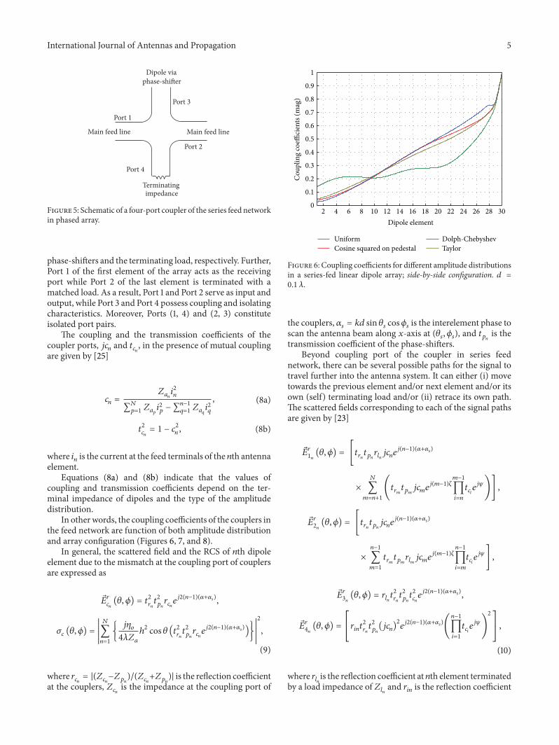
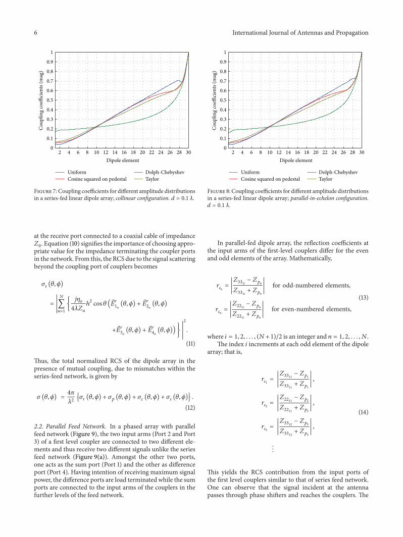
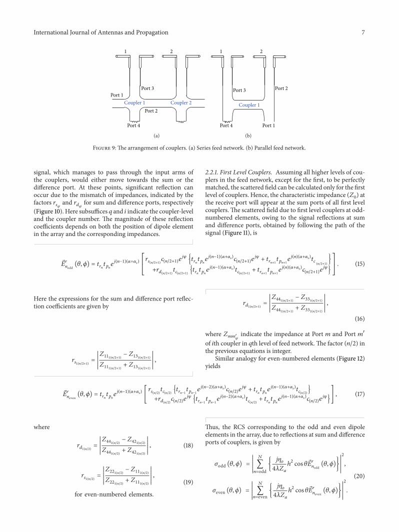
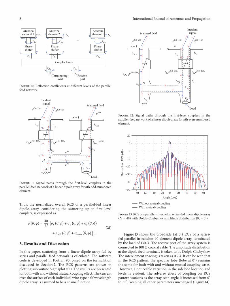
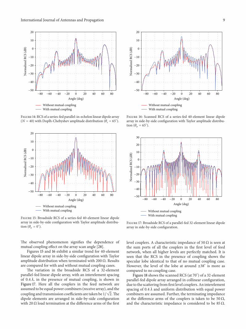
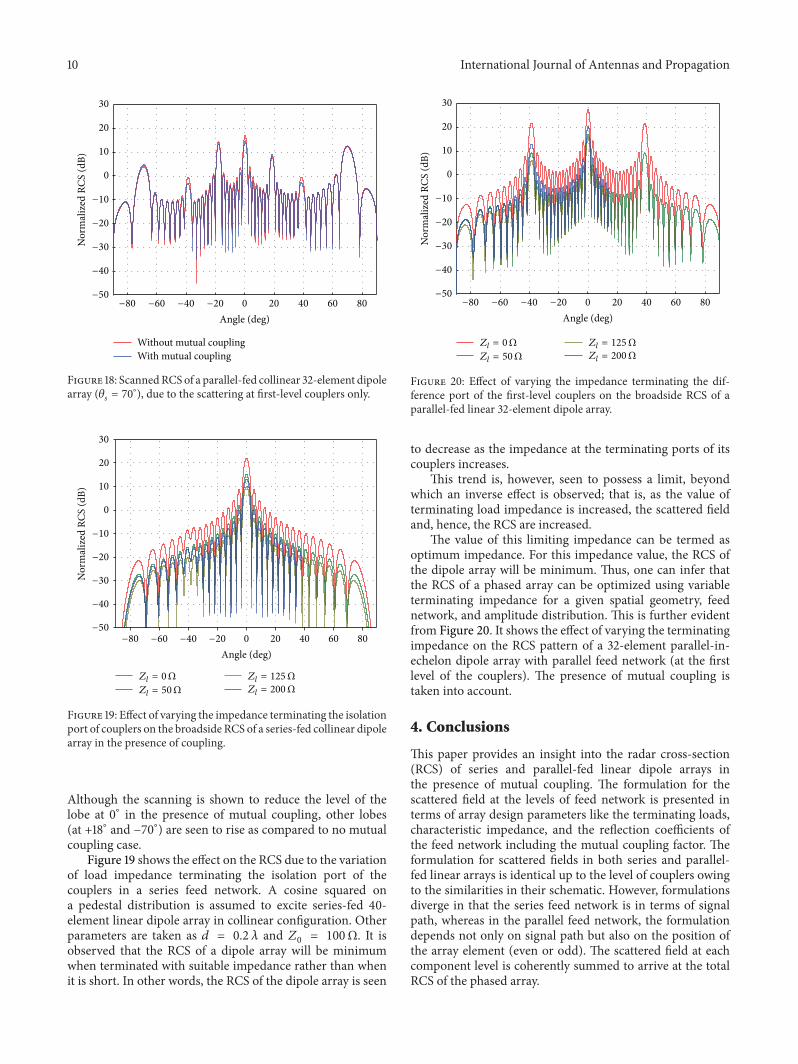

International Journal of
AerospaceEngineeringHindawi Publishing Corporationhttpwwwhindawicom Volume 2014
RoboticsJournal of
Hindawi Publishing Corporationhttpwwwhindawicom Volume 2014
Hindawi Publishing Corporationhttpwwwhindawicom Volume 2014
Active and Passive Electronic Components
Control Scienceand Engineering
Journal of
Hindawi Publishing Corporationhttpwwwhindawicom Volume 2014
International Journal of
RotatingMachinery
Hindawi Publishing Corporationhttpwwwhindawicom Volume 2014
Hindawi Publishing Corporation httpwwwhindawicom
Journal ofEngineeringVolume 2014
Submit your manuscripts athttpwwwhindawicom
VLSI Design
Hindawi Publishing Corporationhttpwwwhindawicom Volume 2014
Hindawi Publishing Corporationhttpwwwhindawicom Volume 2014
Shock and Vibration
Hindawi Publishing Corporationhttpwwwhindawicom Volume 2014
Civil EngineeringAdvances in
Acoustics and VibrationAdvances in
Hindawi Publishing Corporationhttpwwwhindawicom Volume 2014
Hindawi Publishing Corporationhttpwwwhindawicom Volume 2014
Electrical and Computer Engineering
Journal of
Advances inOptoElectronics
Hindawi Publishing Corporation httpwwwhindawicom
Volume 2014
The Scientific World JournalHindawi Publishing Corporation httpwwwhindawicom Volume 2014
SensorsJournal of
Hindawi Publishing Corporationhttpwwwhindawicom Volume 2014
Modelling amp Simulation in EngineeringHindawi Publishing Corporation httpwwwhindawicom Volume 2014
Hindawi Publishing Corporationhttpwwwhindawicom Volume 2014
Chemical EngineeringInternational Journal of Antennas and
Propagation
International Journal of
Hindawi Publishing Corporationhttpwwwhindawicom Volume 2014
Hindawi Publishing Corporationhttpwwwhindawicom Volume 2014
Navigation and Observation
International Journal of
Hindawi Publishing Corporationhttpwwwhindawicom Volume 2014
DistributedSensor Networks
International Journal of