Embed Size (px)
Citation preview

Research ArticleTarget Detection in Low Grazing Angle withAdaptive OFDM Radar
Yang Xia Zhiyong Song Zaiqi Lu Hao Wu and Qiang Fu
ATR Key Laboratory National University of Defense Technology Changsha Hunan 410073 China
Correspondence should be addressed to Yang Xia xiayang2020126com
Received 10 June 2015 Revised 31 August 2015 Accepted 7 October 2015
Academic Editor Kyeong Jin Kim
Copyright copy 2015 Yang Xia et alThis is an open access article distributed under the Creative Commons Attribution License whichpermits unrestricted use distribution and reproduction in any medium provided the original work is properly cited
Multipath effect is the main factor of deteriorating target detection performance in low grazing angle scenario which results fromreflections on the groundsea surface Amplitudes of the received signals fluctuate acutely due to the random phase variations ofreflected signals along different paths thereby the performances of target detection and tracking are heavily influencedThis paperdeals with target detection in low grazing angle scenario with orthogonal frequency division multiplexing (OFDM) radar Realisticphysical and statistical effects are incorporated into themultipath propagationmodel By taking advantage ofmultipath propagationthat provides spatial diversity of radar system and frequency diversity of OFDMwaveform we derive a detection method based ongeneralized likelihood ratio test (GLRT) Then we propose an algorithm to optimally design the transmitted subcarrier weights toimprove the detection performance Simulation results show that the detection performance can be improved due to the multipatheffect and adaptive OFDM waveform design
1 Introduction
Target detection and tracking in low grazing angle scenario isone of themost challenging problems in radar community [1]Multipath effect is the main problem when detecting targetsin low grazing angle scenario Amplitudes of received signalsfluctuate acutely due to random phase (which is decidedby differential path length wavelength and characteristicsof reflected surface [2]) variations between different pathsthereby the detection performance is deteriorated Currentlyresearches on multipath effect are mainly focused on twoaspects suppressing multipath and utilizing it [3] Fromanother point of view multipath echoes also contain targetenergy and the detection performance may be enhanced ifthe energy from multipath reflections is accumulated
Orthogonal frequency division multiplexing (OFDM)was originally proposed as a digital modulation technique incommunication fields Later on it was introduced into radarcommunity [4] As a new broadband radar signal OFDMsignal advances in high spectral efficiency low probabilityof intercept and frequency diversity [5ndash7] An adaptive
technique to design the spectrum of OFDM was proposedin [8] by incorporating the scattering coefficients of thetarget at multiple frequencies and the results showed thatthe wideband ambiguity function (WAF) was improved dueto the adaptive waveform design Similar OFDM waveformdesign method can also be found in [9 10]
Focusing on the issue of target detection in urbanenvironment an optimized detection algorithm based onOFDM radar was proposed in [11 12] The results demon-strated that the detection performance was improved byutilizing multipath reflections However the proposed signalmodel was idealistic and only considered specular reflectionsThe problem of target detection in multipath scenarioswas reformulated as sparse spectrum estimation where thespectral parameters of OFDM radar signal are optimizedto improve the detection performance using multiobjectiveoptimization (MOO) technique [13 14]The performances ofgeneralized likelihood ratio test (GLRT) detectorwithOFDMradar in non-Gaussian clutter (log-normal Weibull and K-compound) were investigated in [15] where target fluctu-ations were also taken into consideration Consequently
Hindawi Publishing CorporationInternational Journal of Antennas and PropagationVolume 2015 Article ID 147368 12 pageshttpdxdoiorg1011552015147368
2 International Journal of Antennas and Propagation
Radar
Sealand surface
R1
Rd
R2
Target
Image
Figure 1 Representative scenario of multipath propagation in lowgrazing angle
detection performance may be enhanced with OFDM radarin low grazing angle scenario by utilizing multipath reflec-tions
When detecting target in low grazing angle scenarioradar measurements are affected by many factors such asever-changing meteorological conditions in the troposphereEarthrsquos curvature and roughness of groundsea surface [16]All these factors will affect the detection performance andtherefore these factors should be taken into consideration tomake the signal model more realistic
This paper deals with target detection in low grazingangle scenario with OFDM radar To make the propagationmodel more accurate refraction of the lower atmosphere andthe Earthrsquos curvature are taken into consideration and themultipath propagation model is modified accordingly Basedon the characteristics of OFDM radar we derive a GLRTdetector in Gaussian clutter environment Then a waveformdesign method which optimizes the transmitted subcarrierweights is proposed to improve the detection performanceFinally the performance of the proposed detector is analyzedand discussed via simulation experiments
2 Modified Multipath Propagation Model
Multipath effect is one of the main problems when detectingand tracking target in low grazing angle scenario The echosignals received by radar receiver not only include directsignals but also include indirect signals Thus the receivedsignals are the sum of reflected signals along different pathsand the amplitudes fluctuate acutely due to the random phasevariations which deteriorates the performances of targetdetection and tracking Generally speaking signals reflectedmore than twice will be attenuated heavily which can alwaysbe neglected
The representative scenario of multipath propagation inlow grazing angle is shown in Figure 1 Target locates at adistance 119877119889 from the radar The source is assumed to be anarrowband signal which can be represented as [16]
119909 (119905) = 119886119890119895(120596119905+120585)
(1)
where 119886 120596 and 120585 denote the amplitude angular frequencyand initial phase respectively In the presence of multipath
the received signals consist of two components namely thedirect and indirect signals Direct signal is given by
119909119889 (119905) = 119909 (119905) 119890minus119895(2120587120582)(2119877119889) (2)
and the indirect signal is
119909119894 (119905) = 119909 (119905) 120588119890119895120593119890minus119895(2120587120582)119877119894 (3)
In (3) 120588119890119895120593 is the complex reflection coefficient and 119877119894
is the total length of indirect path For first-order reflectedsignals 119877119894 = 1198771 + 1198772 + 119877119889 and for second-order reflectedsignals 119877119894 = 2(1198771 + 1198772) Received signal can be representedas
119909119903 (119905) = 119909119889 (119905) + 119909119894 (119905)
= 119909 (119905) 119890119895(2120587120582)(2119877119889) (1 + 120588119890
119895(120593+(2120587120582)Δ119877))
(4)
whereΔ119877 = 119877119894minus2119877119889 In (4) the amplitudes of received signalsare dependent on the factor120588119890119895(120593+(2120587120582)Δ119877) which includes theeffects of complex reflection coefficient 120588119890119895120593 wavelength 120582and path difference Δ119877
In normal atmospheric conditions the pressure decreasesexponentially with height which causes a reduction in therefractivity with respect to height Under this condition aradio ray will diffract downward [17] Furthermore in mar-itime environment evaporation duct effect may be produceddue to the strong humidity gradients above (within firstfew meters) the air-sea boundary [18] which makes a radioray bend downward with a curvature more than the Earthrsquosradius The effect is dependent on a few factors such astemperature difference between the air and sea and the windspeed [19]
In addition to the atmospheric effects low grazing anglepropagation is also affected by the fact that the Earth iscurved The curvature of the Earth decreases the path lengthdifference between the direct and reflected waves and italso reduces the amplitudes of the reflected waves [19] Thisproblem is usually dealt with by replacing the Earth with animaginary flat Earth whose equivalent radius is
119877119890 = 1198770 (1 + 1198770
119889119873
119889ℎ10minus6)
minus1
(5)
where1198770 is the radius of actual Earth and119889119873119889ℎ is the refrac-tivity gradient For standard atmosphere minus79 le 119889119873119889ℎ le
0N-unitskm [19]Considering all the factors mentioned above and based
on ideal propagation model described in Figure 1 modifiedmultipath propagation model is shown in Figure 2 Theheight of radar and target is ℎ119903 and ℎ119905 respectively Theground distance separated by radar and target is 119903 ℎ1015840
119903and ℎ
1015840
119905
are the modified heights corresponding to radar and targetover flat-Earthmodel 1199031 is the grounddistance between radarand the reflected point and 120595 is the grazing angle
In order to calculate complex reflection coefficient in (4)we have to solve the grazing angle 120595 and Δ119877 first Thesevariables are all related to 1199031 which can be evaluated usingthe following cubic equation [20]
21199033
1minus 3119903119903
2
1+ [119903
2minus 2119877119890 (ℎ119903 + ℎ119905)] 1199031 + 2119877119890ℎ119903119903 = 0 (6)
International Journal of Antennas and Propagation 3
RadarTarget
hr
h998400r
r1 r2
ReRe120601
1206011 1206012
O
ht
h998400t
Tangent planeR1
R2
r
120595
Rd
Figure 2 Modified multipath propagation model
Then we solve ℎ1015840119903and ℎ1015840
119905by
ℎ1015840
119903≃ ℎ119903 minus
1199032
1
2119877119890
ℎ1015840
119905≃ ℎ119905 minus
(119903 minus 1199031)2
2119877119890
(7)
Meanwhile we can get 1206011 = 1199031119877119890 and 1206012 = (119903minus1199031)119877119890 Usinglaw of cosine yields
1198771 =radic1198772
119890+ (119877119890 + ℎ119903)
2minus 2119877119890 (119877119890 + ℎ119903) cos1206011
1198772 =radic1198772
119890+ (119877119890 + ℎ119905)
2minus 2119877119890 (119877119890 + ℎ119905) cos1206012
119877119889
= radic(119877119890 + ℎ119903)2+ (119877119890 + ℎ119905)
2minus 2 (119877119890 + ℎ119903) (119877119890 + ℎ119905) cos120601
(8)
Finally the grazing angle 120595 is given by
120595 =1
2(120587 minus arccos(
1198772
1+ 119877
2
2minus 119877
2
119889
211987711198772
)) (9)
The complex reflection coefficient can be calculated by[20]
120588119890119895120593
= Γ(]ℎ)119863119878 (10)
where Γ(]ℎ) is vertical polarization or horizontal polarizationreflection coefficient for a plane surface 119863 is the divergencefactor due to a curved surface and 119878 is root-mean-squared(RMS) specular scattering coefficient which represents theroughness of surface
Γ(]ℎ) is determined by frequency complex dielectricconstant and grazing angle120595 which can be calculated by [21]
ΓV ≃sin120595radic120576119888 minus 1
sin120595radic120576119888 + 1(11)
for vertical polarization and
Γℎ ≃sin120595 minus radic120576119888
sin120595 + radic120576119888
(12)
for horizontal polarization where 120576119888 is complex dielectricconstant which is given by 120576119888 = 1205761205760 minus 11989560120582120590 1205761205760 is relativedielectric constant of the reflecting medium and 120590 is itsconductivity
When the electromagnetic wave is incident on the surfaceof the Earth due to the slight differences in each incidentray the reflected wave is diverged and the reflected energyis defocusedWhen this happens radar power density will bereduced If the grazing angle is not large divergence factor119863can be approximated by [21]
119863 ≃ (1 +211990311199032
119877119890119903120595)
minus12
(13)
Due to the reflection of rough surface two componentswill be generated a diffuse component and a coherent com-ponent with reducedmagnitudeThe reduction in themagni-tude of the coherent component brought about by reflectionsfrom a rough surface is related to the grazing angle and thesignal wavelength which is [21]
119878 = 119890minus120583 (14)
where
120583 =
2 [2120587120578]2
120578 le 01 rad
0161205782+ 742120578 + 00468 otherwise
(15)
and 120578 is the surface roughness factor defined as 120578 = 120590119867120595120582120590119867 is the RMS of reflection surface and 120590119867120582 denotes theroughness of reflected surface The larger 120590119867120582 is the moreroughness the surface will be For smooth surface 120590119867120582 isapproximated to be zero
Substituting (11)ndash(15) into (10) we can get the complexreflection coefficient 120588119890119895120593 At the same time 120588119890119895(120593+(2120587120582)Δ119877)can be evaluated which is the impact of multipath propaga-tion on signal model
3 Measurement Model of OFDM Radar
We consider a monostatic radar employing an OFDM signal-ing system The transmitted signal can be described as
119904 (119905) =
119872minus1
sum
119898=0
119906 (119905 minus 119898119879119903) 11989011989521205871198910119905 (16)
where 1198910 119872 and 119879119903 represent the carrier frequency pulsenumber and pulse repetition interval (PRI) respectively 119906(119905)is the complex envelop of a single pulse which is given by
119906 (119905) =
119873minus1
sum
119899=0
119908119899rect (119905 119905119887) 1198901198952120587119899Δ119891119905
(17)
where
rect (119905 119905119887) =
1 0 le 119905 le 119905119887
0 otherwise(18)
4 International Journal of Antennas and Propagation
and 119873 is the subcarrier number w = [1199080 1199081 119908119873minus1]119879
represent the complex weights transmitted over differentsubcarriers and satisfying sum
119873minus1
119899=0|119908119899|
2= 1 For the sake
of keeping orthogonality between different subcarriers thesubcarrier spacing Δ119891 and time duration 119905119887 of a single pulseshould satisfy Δ119891119905119887 = 1 The total bandwidth is 119861 = 119873Δ119891
Assuming that the received signals contain 119875 differentpaths and the roundtrip delay corresponding to 119901th path is120591119901 119901 = 0 1 119875 minus 1 The received signal is
119910 (119905) =
119875minus1
sum
119901=0
119904 (120574119901 (119905 minus 120591119901)) (19)
where 120574119901 = 1+120573119901 accounts for the stretching or compressingin time of the reflected signal and 120573119901 = 2⟨k u119901⟩119888 representsthe Doppler spreading factor corresponding to 119901th path kand u119901 are the target velocity and unit direction of arrival(DOA) vector 119888 is the propagation speed Substituting (16)into (19) the received signal after demodulation is denotedby
119910 (119905)
=
119875minus1
sum
119901=0
119872minus1
sum
119898=0
119906 (120574119901 (119905 minus 120591119901) minus 119898119879119903) 11989011989521205871198910120573119901(119905minus1205910)119890
minus119895212058711989101205910
+ 119890 (119905)
(20)
Then substituting (17) into (20) we obtain
119910 (119905) =
119872minus1
sum
119898=0
119873minus1
sum
119899=0
119875minus1
sum
119901=0
119908119899119909119899119901rect (120574119901 (119905 minus 120591119901) minus 119898119879119903 119905119887)
sdot 1198901198952120587119899Δ119891(120574119901(119905minus120591119901)minus119898119879119903)119890
11989521205871198910120573119901(119905minus1205910)119890minus119895212058711989101205910 + 119890 (119905)
(21)
where 119909119899119901 represents the complex scattering coefficient oftarget corresponding to 119899th carrier and 119901th path 1205910 isthe roundtrip delay corresponding to the range cell underconsideration The relative time gaps between different pathsare very small compared to the actual roundtrip delay whichmeans 120591119901 asymp 1205910 for119901 = 0 1 119875minus1 Substituting 119905 = 1205910+119898119879119903
(119898 = 0 1 119872 minus 1) into (21) we obtain
119910 (119899119898) =
119875minus1
sum
119901=0
119908119899119909119899119901120601119899119901 (119898 V) + 119890 (119899119898) (22)
where
120601119899119901 (119898 V) = 119890minus119895212058711989101205910119890
1198952120587119891119899120573119901119898119879119903 (23)
and 119891119899 = 1198910 + 119899Δ119891 Equation (22) can be written into matrixform
y (119898) = WXΦ (119898 k) + e (119898) (24)
where
(i) y(119898) = [119910(0119898) 119910(1119898) 119910(119873minus1119898)]119879 is an119873times1
vector that represents output of the119898th pulse
(ii) W = diag(w) is an 119873 times 119873 complex diagonal matrixthat contains transmitted subcarrier weights
(iii) X = blkdiag (x1198790 x1198791 x119879
119873minus1) is an119873 times119873119875 complex
rectangular block-diagonal matrix x119899 = 119909119899 sdot 120588 119899 =
0 1 119873minus1 where 119909119899 is target scattering coefficienton the 119899th subcarrier and 120588 = [1205880 1205881 120588119875minus1]
119879
represents complex reflection coefficients over differ-ent paths for direct signals 120588119901 = 1 for first-orderreflected signals120588119901 = 120588119890
119895120593 for second-order reflectedsignals 120588119901 = (120588119890
119895120593)2 where 120588119890119895120593 is calculated by (10)
(iv) Φ(119898 k) = [1206010(119898 k) 1206011(119898 k) 120601119873minus1(119898 k)]119879 is an119873119875 times 1 complex vector and 120601119899(119898 k) = [1206011198990(119898 k)1206011198991(119898 k) 120601119899119875minus1(119898 k)]119879 119899 = 0 1 119873 minus 1
(v) e(119898) = [1198900(119898) 1198901(119898) 119890119873minus1(119898)]119879is an119873times 1 com-
plex vector of clutter
Then concatenating all temporal data into119873 times119872matrixthe OFDMmeasurement model in low grazing angle is
Y = WXΦ (k) + E (25)
where
Y = [y (0) y (1) y (119872 minus 1)] (26)
Φ(V) = [Φ(0 V)Φ(1 V) Φ(119872 minus 1 V)] is an 119873119875 times 119872
complex matrix that contains Doppler information over 119872pulses
E = [e(0) e(1) e(119872minus1)] is an119873times119872 complexmatrixthat consists of clutter returns
In low grazing angle scenario the clutter is usuallymodeled as compound-Gaussian model which is the productof speckle and texture [22] The speckle is fast-changing andmodeled as a complex Gaussian process while the texture isslow-changing and modeled as a nonnegative process [23]
In this paper the correlation length of the texture isassumed to be on the order of seconds and we only considerone coherent processing interval (CPI) which is assumedto be 60ms Due to the long correlation time of textureit is considered to be constant within each CPI changingaccording to a given probability density function (PDF) fromone CPI to the next Thus conditioned on a given value ofthe texture the clutter is simplified to Gaussian distributionHowever this simplification is not justified when predictingthe clutterrsquos behavior in time intervals larger than a CPI suchas clutter cancellation and constant false alarm rate (CFAR)detection
Thus we assume that the clutter is temporally whiteand circularly zero-mean complex Gaussian process withunknown positive definite covariance C The measurementsover different pulses are supposed to be independent whichmeans
vec (Y) sim CN119873119872 (vec (WXΦ (k)) C otimes I119872) (27)
whereotimes denotes Kronecker product Accordingly theOFDMmeasurements are distributed as
Y sim CN119873119872 (WXΦ (k) C otimes I119872) (28)
International Journal of Antennas and Propagation 5
4 Detection Test
In low grazing angle scenario received signals are the sumof signals along different paths which form the complicatedmeasurements The essence of detection is to judge whethera target is present or not in the range cell under test This isa classical two-hypothesis detection problem Therefore weconstruct a decision problem to choose between two possiblehypotheses the null hypothesis (target-free hypothesis) andthe alternate hypothesis (target-present hypothesis) whichcan be expressed as
H0 X = 0 C unknown
H1 X = 0 kC unknown(29)
ThemeasurementsY in two hypotheses are distributed as
Y
sim
H0 CN119873119872 (0C otimes I119872) C unknown
H1 CN119873119872 (WXΦ (k) C otimes I119872) kC unknown
(30)
According to the classical target detection theoryNeyman-Pearson (NP) detector is the optimal detector whichmaximizes the probability of detection at a constant prob-ability of false alarm However the target velocity k andclutter covarianceC are unknown andGLRT detector is usedinstead where the unknown parameters are replaced withtheir maximum likelihood estimates (MLEs) The formula-tion of GLRT is [24]
GLR (k) =119891 (Y | H1 k X C1)
119891 (Y | H0 C0)
H1
≶
H0
120574 (31)
where 119891(Y | H1) and 119891(Y | H0) are the likelihood functionsunder H1 and H0 respectively 120574 is the threshold that thedetector is compared with X and C1 are the MLE of X and CunderH1 while C0 is the MLE of C underH0
Definition 1 If the random matrix Y(119873 times 119872) is distributedas a matrix variate normal distribution (MVND) with meanM(119873 times 119872) and covariance Ω otimes Σ we use the notation Y sim
CN119873119872(MΩotimesΣ) and the probability density function (PDF)is given by [25]
119891 (Y)
=
exp (minus (12) tr [Ωminus1 (Y minusM)Σminus1(Y minusM)
119867])
(2120587)1198731198722
|Ω|1198732
|Σ|1198722
(32)
where tr(sdot) is the trace of matrixΩ and Σ are positive definitecovariance matrices over the column and row of Y Ω is an119873 times 119873 matrix and Σ is an 119872 times119872 matrix which are definedas [25]
Ω = 119864 [(Y minusM) (Y minusM)119867]
Σ = 119864 [(Y minusM)119867(Y minusM)]
(33)
According to the above descriptions we can derive PDFsof the measurements under two hypotheses
119891 (Y | H0) =
exp (minus (12) tr [Cminus10YY119867])
(2120587)1198731198722 1003816100381610038161003816C0
1003816100381610038161003816
1198732 (34)
119891 (Y | H1)
=
exp (minus (12) tr [Cminus11(Y minusWXΦ (k)) (Y minusWXΦ (k))119867])
(2120587)1198731198722 1003816100381610038161003816C1
1003816100381610038161003816
1198732
(35)
The log-likelihood function of (35) is
ln119891 (Y | H1)
= minus119872119873
2ln (2120587) minus 119873
2ln 1003816100381610038161003816C1
1003816100381610038161003816
minus1
2tr [Cminus1
1(Y minusWXΦ (k)) (Y minusWXΦ (k))119867]
(36)
Taking derivative of (36) with respect to C1 and makingit equal to zero the MLE of C1 is
C1 =1
119873(Y minusWXΦ (k)) (Y minusWXΦ (k))119867 (37)
Substituting (37) into (36) yields
XML
= argminX
ln 10038161003816100381610038161003816(Y minusWXΦ (k)) (Y minusWXΦ (k))11986710038161003816100381610038161003816 (38)
Usually the scattering matrix X does not yield a close-form MLE expression However noting that X has a block-diagonal structure it turns out to be a block-diagonal growthcurve (BDGC) problem Reference [26] derived the approx-imate maximum likelihood (AML) estimator for X which isgiven by
xAML = vecb (X) = (Γ119867Γ)minus1
Γ119867vec (Tminus12XΠΦ) (39)
where
Γ ≜ Φ119879⊛ (T12W)
T ≜ YΠperpΦY119867
ΠΦ ≜ Φ (k)119867 (Φ (k)Φ (k)119867)minus
Φ (k)
Πperp
Φ≜ I minusΠΦ
(40)
vecb(sdot) and ⊛ denote block-diagonal matrix vectorizationoperator and generalized Khatri-Rao product [27] respec-tively ΠΦ and Πperp
Φare orthogonal projection matrix of Φ(k)
and (sdot)minus represents generalized inverse of matrix (eg a
generalized inverse of matrix S is defined as Sminus such thatSSminusS = S) [27]
The log-likelihood function of (34) is
ln119891 (Y | H0) = minus119872119873
2ln (2120587) minus 119873
2ln 1003816100381610038161003816C0
1003816100381610038161003816
minus1
2tr [Cminus1
0YY119867]
(41)
6 International Journal of Antennas and Propagation
Taking derivative of (41) with respect toC0 andmaking itequal to zero we get MLE of C0
C0 =1
119873YY119867 (42)
Substituting (34) (35) (37) and (42) into (31) the GLRTdetector is
GLR (k) =10038161003816100381610038161003816C0
1003816100381610038161003816100381610038161003816100381610038161003816C1
10038161003816100381610038161003816
=
10038161003816100381610038161003816(1119873)YY11986710038161003816100381610038161003816
100381610038161003816100381610038161003816(1119873) (Y minusWXΦ (k)) (Y minusWXΦ (k))
119867100381610038161003816100381610038161003816
(43)
Since target velocity k is unknown it can be estimatedthrough k = argmaxkGLR(k) andtheGLRTdetector becomes
maxk
GLR (k) = GLR (k)H1
≶
H0
120574 (44)
5 Adaptive Waveform Design
In this section we develop an adaptive waveform designmethod based on maximizing the Mahalanobis-distanceto improve the detection performance Since the targetscattering coefficients vary with different subcarriers wemay change the transmitted weights W accordingly From(30) we know that the measurement Y is distributedas CN119873119872(WXΦ(k)C otimes I119872) under H1 hypothesis andCN119873119872(0C otimes I119872) under H0 hypothesis The squaredMahalanobis-distance is used to distinguish the above twodistributions It is noticeable that the column ofY is uncorre-lated which means that the measurements between differentpulses are independent The sum of squared Mahalanobis-distance over different pulses is given by [28]
1198892=
119872minus1
sum
119898=0
120573119898 (WXΦ ( 119898))119867Cminus1 (WXΦ ( 119898)) (45)
where120573119898 is a positive number and denotes theweight ofMaha-lanobis-distance over the119898th pulse satisfying sum119872minus1
119898=0120573119898 = 1
To maximize the detection performance we can formulatethe optimization as
wopt = arg maxWisinC119873
[
119872minus1
sum
119898=0
120573119898 (WXΦ ( 119898))119867Cminus1 (WXΦ ( 119898))]
subject to w119867w = 1
(46)
The scattering coefficients are constant from pulse topulse and the measurement noise is uncorrelated betweendifferent pulses thus 120573119898 is a constant number that is 120573119898 =
1119872 for119898 = 0 1 119872 minus 1 Since
(WXΦ ( 119898))119867Cminus1 (WXΦ ( 119898))
= tr (Φ ( 119898)119867X119867W119867Cminus1WXΦ ( 119898))
= tr (Cminus1WXΦ ( 119898)Φ ( 119898)119867X119867W119867
)
(47)
the following theorem [11] is used to simplify the aboveequation
tr (S1AS2A119867) = a119867 [S119879
2⊙ S1] a (48)
where a isin C119873 and A = diag(a) ⊙ denotes element-wiseHadamard product Combining (47) and (48) we get
wopt = arg maxWisinC119873
(1
119872)w119867 [
119872minus1
sum
119898=0
(XΦ ( 119898)Φ ( 119898)119867X119867)
119879
⊙ Cminus1]w
subject to w119867w = 1
(49)
From (49) we know that the optimization problemis reduced to eigenvalue eigenvector problem and wopt isthe eigenvector corresponding to the largest eigenvalue of[sum
119872minus1
119898=0(XΦ( 119898)Φ( 119898)
119867X119867)119879 ⊙ Cminus1]
6 Numerical Results
In this section several numerical examples are presentedto illustrate the performance of proposed detector For
simplicity we consider 2D scenario as shown in Figure 2Thesimulation parameters are shown in Table 1
We use Monte Carlo simulations to realize the followingresults for the analytical expression between false alarm rateand threshold cannot be acquired The relation betweenprobability of false alarm rate and detection threshold corre-sponding to different carrier numbers is shown in Figure 3The curves show that when false alarm rate is kept fixed
International Journal of Antennas and Propagation 7
1
15
2
25
3
35
4
45
5
Det
ectio
n th
resh
old
(Th)
Probability of false alarm (Pfa)10minus3 10minus210minus5 10minus4 10minus1
N = 1
N = 3
N = 5
Figure 3 Detection threshold versus probability of false alarm at different carrier numbers
Table 1 Parameter settings of the simulations
Parameters ValuesHeight of target 200mVelocity of target [1414 1414]119879msScattering coefficient matrix of target X CN(0 1)
Height of radar platform 100mVelocity of radar platform [0 0]119879msRelative distance between radar and target 5 kmMultipath number 119875 3Carrier frequency 1198910 1 GHzBandwidth 119861 100MHzCarrier numbers119873 3Frequency weightsW 1radic119873I119873Pulse number119872 30Pulse repetition interval 119879119903 2ms
the higher the subcarrier number the higher the thresholdSignal-to-noise ratio (SNR) is defined as [11]
SNR =(1119873)sum
119872
119898=1(WX120601 (119898 k))119867WX120601 (119898 k)
tr (C) (50)
The effect of multipath number on the detection perfor-mance is shown in Figure 4 where the path number is setas 119875 = 1 and 119875 = 3 Figures 4(a) and 4(b) show 119875119889 versusSNR with different 119875fas and 119875119889 versus 119875fa when SNR is fixedto minus20 dB respectively The curves show that the detectionperformance is improved with the increasing of multipathnumber Consequently the derived detector with OFDM
waveform could exploit multipath reflections to enhance thedetection performance
In Figure 5 we analyze the effect of subcarrier number onthe performance of proposed detector where the subcarriernumber is set as 119873 = 1 3 and 5 respectively Figures 5(a)and 5(b) show 119875119889 versus SNR when 119875fa = 10
minus3 and 119875119889
versus 119875fa when SNR is fixed to minus20 dB respectively Thedetection performance is improved with the increasing ofsubcarrier number The results demonstrate that the detec-tion performance is improved due to the frequency diversityin an OFDM radar system
Figure 6 shows that the detection performance varieswith the target height which is set as 200m 400m and600m respectively Figure 6(a) shows 119875119889 versus SNR when119875fa = 10
minus3 while Figure 6(b) shows 119875119889 versus 119875fa when SNRis fixed to minus20 dB The results demonstrate that detectionperformance decreases with the increasing of target height inlow grazing angle scenario This can be explained that as thetarget height increases the grazing angle gets larger and thecomplex reflection coefficient over indirect paths becomessmaller which is shown in Figure 7 Thus the detectionperformance deteriorates
In Figure 8 we analyze the effect of varying the directionsof target velocity vector on the detection performance Herek119879 = [100 0] [717 717] and [0 100]ms respectivelyFigures 8(a) and 8(b) show 119875119889 versus SNR when 119875fa = 10
minus3
and 119875119889 versus 119875fa when SNR is fixed to minus20 dB respectivelyIn this paper we take advantage of multipath propagationby exploiting multiple Doppler shifts corresponding to theprojections of target velocity on each of the multipathcomponents When the angle between the target velocityvector and radar LOS decreases the Doppler frequency of
8 International Journal of Antennas and Propagation
minus35 minus30 minus25 minus20 minus15 minus10 minus5 0 50
02
04
06
08
1
SNR (dB)
Prob
abili
ty o
f det
ectio
n (P
d)
P = 1 Pfa = 10minus3
P = 3 Pfa = 10minus3P = 1 Pfa = 10minus5
P = 3 Pfa = 10minus5
(a) 119875119889 versus SNR with different 119875fas
02
03
04
05
06
07
08
09
1
Probability of false alarm (Pfa)10minus3 10minus2 10minus1 100
Prob
abili
ty o
f det
ectio
n (P
d)
P = 1
P = 3
(b) 119875119889 versus 119875fa when SNR = minus20 dB
Figure 4 Effect of the path number on the detection performance
minus30 minus20 minus10 00
02
04
06
08
1
SNR (dB)
Prob
abili
ty o
f det
ectio
n (P
d)
N = 1
N = 3
N = 5
(a) 119875119889 versus SNR when 119875fa = 10minus3
0
02
04
06
08
1
Probability of false alarm (Pfa)
Prob
abili
ty o
f det
ectio
n (P
d)
10minus3 10minus2 10minus1 100
N = 1
N = 3
N = 5
(b) 119875119889 versus 119875fa when SNR = minus20 dB
Figure 5 Effect of the subcarrier number on the detection performance
received signal will increaseThus the detection performanceis improved
In Figure 9 we show the detection performance improve-ment due to the adaptive waveform design Figure 9(a) shows119875119889 versus SNR when 119875fa = 10
minus3 while Figure 9(b) shows 119875119889versus 119875fa when SNR is fixed to minus20 dB We assume that thetransmitted waveform in the first119872 pulses has equal weightsthat is w = 1radic119873I Then based on (49) we compute woptfor the next 119872 pulses As is shown compared with fixed
waveform the detection performance is improved due to theadaptive waveform method proposed in this paper
Finally to validate our method in non-Gaussian scenar-ios we conduct additional experiments using compound K-distribution whose PDF is [29]
119891 (119911) =radic2V120583Γ (V)
(radic2V120583119911)
V
119870Vminus1(radic2V120583119911) (51)
International Journal of Antennas and Propagation 9
minus30 minus20 minus10 00
02
04
06
08
1
SNR (dB)
Prob
abili
ty o
f det
ectio
n (P
d)
ht = 200mht = 400mht = 600m
(a) 119875119889 versus SNR when 119875fa = 10minus3
01
02
03
04
05
06
07
08
09
Probability of false alarm (Pfa)
Prob
abili
ty o
f det
ectio
n (P
d)
10minus3 10minus2 10minus1 100
ht = 200mht = 400mht = 600m
(b) 119875119889 versus 119875fa when SNR = minus20 dB
Figure 6 Detection performance varies with target height
0 500 1000 1500 20000
02
04
06
08
1
Am
plitu
de o
f com
plex
refle
ctio
n co
effici
ent
Horizontal polarizationVertical polarization
Target height m
Figure 7 Amplitude of complex reflection coefficient varies with target height
and the texture follows a gamma distribution with PDF
119891 (119906) =1
Γ (V)(V120583)
V
119906Vminus1
119890minusV120583119906
120581 (119906) (52)
where Γ(sdot) is the Eulerian gamma function 120581(sdot) is the unitstep function and 119870Vminus1(sdot) is the modified Bessel function ofsecond kind with order V minus 1 120583 and V are the scale and shapeparameter respectively The speckle component is assumed
to be a Gaussian distribution with exponential correlationstructure covariance matrix [30]
[C]119894119895 = 120588|119894minus119895|
for 119894 119895 = 0 1 119873 minus 1 (53)
where 120588 is one-lag correlation coefficient The other parame-ters are the same as in Table 1
Figure 10 shows the detection performance with differentpath numbers (119875 = 1 3) in Gaussian and compound
10 International Journal of Antennas and Propagation
minus30 minus20 minus10 00
02
04
06
08
1
SNR (dB)
Prob
abili
ty o
f det
ectio
n (P
d)
x = 100 y = 0msx = y = 717msx = 0 y = 100ms
(a) 119875119889 versus SNR when 119875fa = 10minus3
04
05
06
07
08
09
1
Probability of false alarm (Pfa)
Prob
abili
ty o
f det
ectio
n (P
d)
10minus3 10minus2 10minus1 100
x = 100 y = 0msx = y = 717msx = 0 y = 100ms
(b) 119875119889 versus 119875fa when SNR = minus20 dB
Figure 8 Effect of different directions of target velocity on detection performance
minus35 minus30 minus25 minus20 minus15 minus10 minus5 0 50
02
04
06
08
1
SNR (dB)
Prob
abili
ty o
f det
ectio
n (P
d)
N = 3 fixed waveformsN = 3 adaptive waveforms
N = 5 fixed waveformsN = 5 adaptive waveforms
(a) 119875119889 versus SNR when 119875fa = 10minus3
04
05
06
07
08
09
1
Probability of false alarm (Pfa)
Prob
abili
ty o
f det
ectio
n (P
d)
10minus3 10minus2 10minus1 100
N = 3 fixed waveformsN = 3 adaptive waveforms
N = 5 fixed waveformsN = 5 adaptive waveforms
(b) 119875119889 versus 119875fa when SNR = minus20 dB
Figure 9 Comparison of detection performance with fixed waveform and adaptive waveform
K-distribution clutter and Figure 11 shows the detectionperformance with fixed and adaptive waveform design inGaussian and compound K-distribution clutter We find thatin compound K-distribution the detector derived underGaussian assumption also yields improved performance bytaking advantage of multipath effect and adaptive waveformdesign of OFDM radar However the performance gap existsdue to the model mismatch
7 Conclusions
In this paper we address the problem of target detectionin low grazing angle scenario with OFDM radar We con-sider the realistic physical and statistical effects to makethe propagation model more realistic Based on the char-acteristics of OFDM signal we develop a GLRT detectorand show that detection performance is improved due tothe multipath utilization and frequency diversity of OFDM
International Journal of Antennas and Propagation 11
0
02
04
06
08
1
Probability of false alarm (Pfa)
Prob
abili
ty o
f det
ectio
n (P
d)
10010minus110minus210minus3
P = 1 GaussianP = 3 Gaussian
P = 1 compound KP = 3 compound K
Figure 10 Effect of themultipath number ondetection performancein Gaussian and compound K-distribution clutter
02
03
04
05
06
07
08
09
1
Fixed waveform GaussianAdaptive waveform GaussianFixed waveform compound KAdaptive waveform compound K
Probability of false alarm (Pfa)
Prob
abili
ty o
f det
ectio
n (P
d)
10minus3 10minus2 10minus1 100
Figure 11 Comparison of detection performance with fixed andadaptive waveform in Gaussian and compound K-distributionclutter (119875 = 3)
radar Then an adaptive waveform design method basedon Mahalanobis-distance is proposed and the detectionperformance is improved due to the optimized transmittedfrequency weights Finally we show that the GLRT detectorderived under Gaussian assumption yields improved perfor-mance in compound K-distribution clutter due to the multi-path utilization and adaptive waveform design However theperformance gap exists and we will extend our work to moregeneral situations in the future work
Conflict of Interests
The authors declare that there is no conflict of interestsregarding the publication of this paper
Acknowledgment
This work was supported in part by the National ScienceFoundation of China under Grant no 61401475
References
[1] D K Barton ldquoLow-angle radar trackingrdquo Proceedings of theIEEE vol 62 no 6 pp 687ndash704 1974
[2] S L Silon and B D Carlson ldquoRadar detection in multipathrdquoIEE ProceedingsmdashRadar Sonar and Navigation vol 146 no 1pp 45ndash54 1999
[3] J-H Zhao and J-Y Yang ldquoFrequency diversity to low-angledetecting using a highly deterministic multipath signal modelrdquoin Proceedings of the 6th CIE International Conference on Radar(ICR rsquo06) pp 1ndash5 IEEE Shanghai China October 2006
[4] M Jankiraman B J Wessels and P van Genderen ldquoDesign ofa multifrequency FMCW radarrdquo in Proceedings of the 28thEuropean Microwave Conference (EuMC rsquo98) pp 584ndash589Amsterdam The Netherlands October 1998
[5] N Levanon ldquoMultifrequency complementary phase-codedradar signalrdquo IEE Proceedings Radar Sonar andNavigation vol147 no 6 pp 276ndash284 2000
[6] R Mohseni A Sheikhi and M A Masnadi-Shirazi ldquoMulticar-rier constant envelope OFDM signal design for radar applica-tionsrdquo AEU International Journal of Electronics and Communi-cations vol 64 no 11 pp 999ndash1008 2010
[7] G Lellouch A Mishra and M Inggs ldquoImpact of the Dopplermodulation on the range and Doppler processing in OFDMradarrdquo in Proceedings of the IEEE Radar Conference (RadarConrsquo14) pp 803ndash808 Cincinnati Ohio USA May 2014
[8] S Sen and A Nehorai ldquoAdaptive design of OFDM radarsignal with improved wideband ambiguity functionrdquo IEEETransactions on Signal Processing vol 58 no 2 pp 928ndash9332010
[9] G Lellouch and A K Mishra ldquoOptimization of OFDM radarwaveforms using geneticalgorithmsrdquo httparxivorgabs14054894
[10] K Huo Z K Qiu Y X Liu and W D Jiang ldquoAn adaptivewaveform design method for OFDM cognitive radarrdquo in Pro-ceedings of the International Radar Conference pp 1ndash5 IEEELille France October 2014
[11] S Sen and A Nehorai ldquoAdaptive OFDM radar for targetdetection in multipath scenariosrdquo IEEE Transactions on SignalProcessing vol 59 no 1 pp 78ndash90 2011
[12] S Sen M Hurtado and A Nehorai ldquoAdaptive OFDM radar fordetecting a moving target in urban scenariosrdquo in Proceedingsof the International Waveform Diversity and Design Conference(WDD rsquo09) pp 268ndash272 IEEE Orlando Fla USA February2009
[13] S Sen G Tang andANehorai ldquoMultiobjective optimization ofOFDM radar waveform for target detectionrdquo IEEE Transactionson Signal Processing vol 59 no 2 pp 639ndash652 2011
[14] S Sen G Tang andANehorai ldquoOFDMradarwaveformdesignfor sparsity-based multi-target trackingrdquo in Proceedings of the
12 International Journal of Antennas and Propagation
InternationalWaveformDiversity and Design Conference (WDDrsquo10) pp 18ndash22 IEEE Niagara Falls Canada August 2010
[15] S Kafshgari and R Mohseni ldquoFluctuating target detectionin presence of non Gaussian clutter in OFDM radarsrdquo AEUInternational Journal of Electronics andCommunications vol 67no 10 pp 885ndash893 2013
[16] W D White ldquoLow-angle radar tracking in the presence ofmultipathrdquo IEEE Transactions on Aerospace and ElectronicSystems vol 10 no 6 pp 835ndash852 1974
[17] S Sen and A Nehorai ldquoOFDM MIMO radar with mutual-information waveform design for low-grazing angle trackingrdquoIEEE Transactions on Signal Processing vol 58 no 6 pp 3152ndash3162 2010
[18] H V Hitney J H Richter R A Pappert K D Anderson andG B Baumgartner Jr ldquoTropospheric radio propagation assess-mentrdquo Proceedings of the IEEE vol 73 no 2 pp 265ndash283 1985
[19] H Hitney and R Vieth ldquoStatistical assessment of evaporationduct propagationrdquo IEEE Transactions on Antennas and Propa-gation vol 38 no 6 pp 794ndash799 1990
[20] M W Long Radar Reflectivity of Land Sea Artech House 3rdedition 2001
[21] T Lo and J Litva ldquoUse of a highly deterministicmultipath signalmodel in low-angle trackingrdquo IEE Proceedings FmdashRadar andSignal Processing vol 138 no 2 pp 163ndash171 1991
[22] F Gini M V Greco M Diani and L Verrazzani ldquoPerformanceanalysis of two adaptive radar detectors against non-Gaussianreal sea clutter datardquo IEEE Transactions on Aerospace andElectronic Systems vol 36 no 4 pp 1429ndash1439 2000
[23] K James Sangston F Gini M V Greco and A Farina ldquoStruc-tures for radar detection in compound gaussian clutterrdquo IEEETransactions on Aerospace and Electronic Systems vol 35 no 2pp 445ndash458 1999
[24] S M Kay Fundamentals of Statistical Signal Processing Detec-tion Theory Prentice Hall PTR Upper Saddle River NJ USA1998
[25] T W Anderson An Introduction to Multivariate StatisticalAnalysis Wiley Series in Probability and Statistics Wiley-Inter-science John Wiley amp Sons Hoboken NJ USA 3rd edition2003
[26] L Xu P Stoica and J Li ldquoA block-diagonal growth curvemodelrdquo Digital Signal Processing vol 16 no 6 pp 902ndash9122006
[27] A Dogandzic and A Nehorai ldquoGeneralized multivariate anal-ysis of variance a unified framework for signal processing incorrelated noiserdquo IEEE Signal Processing Magazine vol 20 no5 pp 39ndash54 2003
[28] R DeMaesschalck D Jouan-Rimbaud and D L Massart ldquoTheMahalanobis distancerdquo Chemometrics and Intelligent Labora-tory Systems vol 50 no 1 pp 1ndash18 2000
[29] E Conte M Longo andM Lops ldquoModelling and simulation ofnon-Rayleigh radar clutterrdquo IEE Proceedings F Radar and SignalProcessing vol 138 no 2 pp 121ndash130 1991
[30] G Cui L Kong and X Yang ldquoMultiple-input multiple-outputradar detectors design in non-Gaussian clutterrdquo IET RadarSonar amp Navigation vol 4 no 5 pp 724ndash732 2010
International Journal of
AerospaceEngineeringHindawi Publishing Corporationhttpwwwhindawicom Volume 2014
RoboticsJournal of
Hindawi Publishing Corporationhttpwwwhindawicom Volume 2014
Hindawi Publishing Corporationhttpwwwhindawicom Volume 2014
Active and Passive Electronic Components
Control Scienceand Engineering
Journal of
Hindawi Publishing Corporationhttpwwwhindawicom Volume 2014
International Journal of
RotatingMachinery
Hindawi Publishing Corporationhttpwwwhindawicom Volume 2014
Hindawi Publishing Corporation httpwwwhindawicom
Journal ofEngineeringVolume 2014
Submit your manuscripts athttpwwwhindawicom
VLSI Design
Hindawi Publishing Corporationhttpwwwhindawicom Volume 2014
Hindawi Publishing Corporationhttpwwwhindawicom Volume 2014
Shock and Vibration
Hindawi Publishing Corporationhttpwwwhindawicom Volume 2014
Civil EngineeringAdvances in
Acoustics and VibrationAdvances in
Hindawi Publishing Corporationhttpwwwhindawicom Volume 2014
Hindawi Publishing Corporationhttpwwwhindawicom Volume 2014
Electrical and Computer Engineering
Journal of
Advances inOptoElectronics
Hindawi Publishing Corporation httpwwwhindawicom
Volume 2014
The Scientific World JournalHindawi Publishing Corporation httpwwwhindawicom Volume 2014
SensorsJournal of
Hindawi Publishing Corporationhttpwwwhindawicom Volume 2014
Modelling amp Simulation in EngineeringHindawi Publishing Corporation httpwwwhindawicom Volume 2014
Hindawi Publishing Corporationhttpwwwhindawicom Volume 2014
Chemical EngineeringInternational Journal of Antennas and
Propagation
International Journal of
Hindawi Publishing Corporationhttpwwwhindawicom Volume 2014
Hindawi Publishing Corporationhttpwwwhindawicom Volume 2014
Navigation and Observation
International Journal of
Hindawi Publishing Corporationhttpwwwhindawicom Volume 2014
DistributedSensor Networks
International Journal of
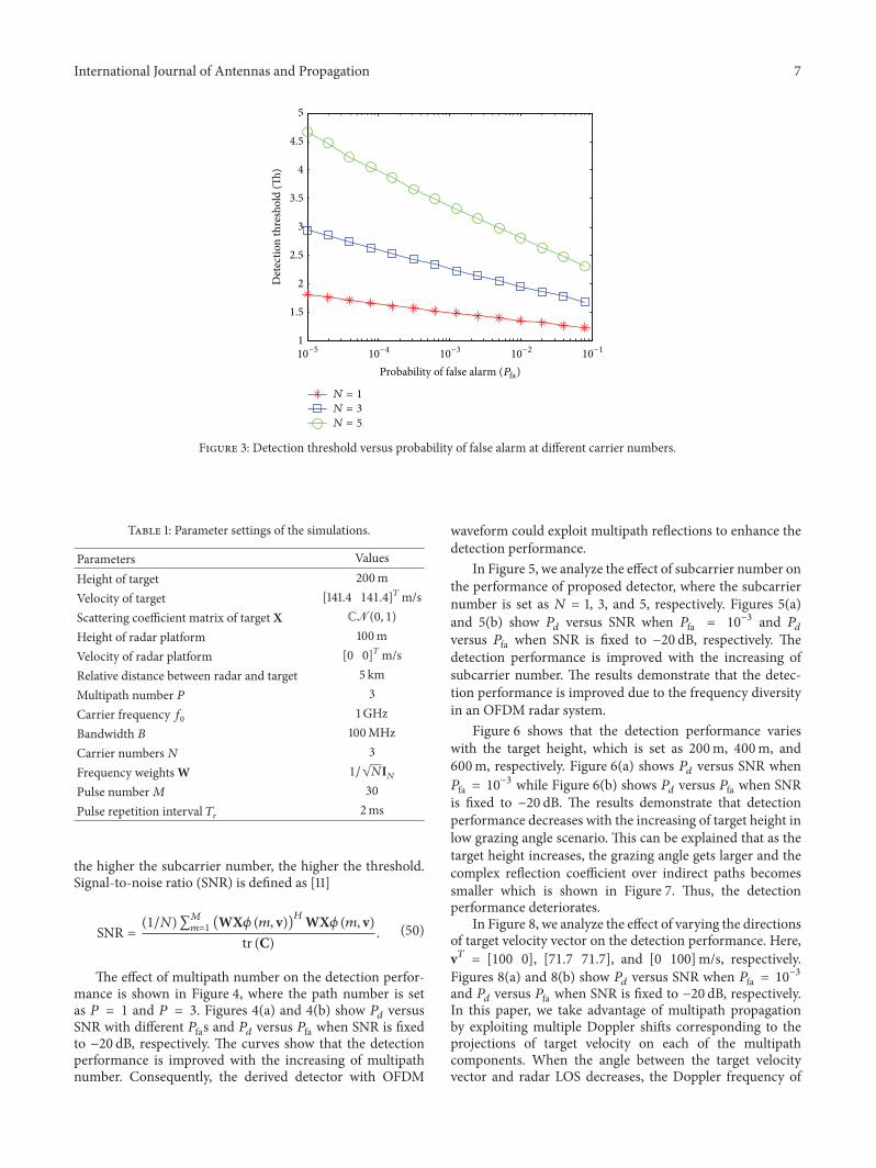

International Journal of
AerospaceEngineeringHindawi Publishing Corporationhttpwwwhindawicom Volume 2014
RoboticsJournal of
Hindawi Publishing Corporationhttpwwwhindawicom Volume 2014
Hindawi Publishing Corporationhttpwwwhindawicom Volume 2014
Active and Passive Electronic Components
Control Scienceand Engineering
Journal of
Hindawi Publishing Corporationhttpwwwhindawicom Volume 2014
International Journal of
RotatingMachinery
Hindawi Publishing Corporationhttpwwwhindawicom Volume 2014
Hindawi Publishing Corporation httpwwwhindawicom
Journal ofEngineeringVolume 2014
Submit your manuscripts athttpwwwhindawicom
VLSI Design
Hindawi Publishing Corporationhttpwwwhindawicom Volume 2014
Hindawi Publishing Corporationhttpwwwhindawicom Volume 2014
Shock and Vibration
Hindawi Publishing Corporationhttpwwwhindawicom Volume 2014
Civil EngineeringAdvances in
Acoustics and VibrationAdvances in
Hindawi Publishing Corporationhttpwwwhindawicom Volume 2014
Hindawi Publishing Corporationhttpwwwhindawicom Volume 2014
Electrical and Computer Engineering
Journal of
Advances inOptoElectronics
Hindawi Publishing Corporation httpwwwhindawicom
Volume 2014
The Scientific World JournalHindawi Publishing Corporation httpwwwhindawicom Volume 2014
SensorsJournal of
Hindawi Publishing Corporationhttpwwwhindawicom Volume 2014
Modelling amp Simulation in EngineeringHindawi Publishing Corporation httpwwwhindawicom Volume 2014
Hindawi Publishing Corporationhttpwwwhindawicom Volume 2014
Chemical EngineeringInternational Journal of Antennas and
Propagation
International Journal of
Hindawi Publishing Corporationhttpwwwhindawicom Volume 2014
Hindawi Publishing Corporationhttpwwwhindawicom Volume 2014
Navigation and Observation
International Journal of
Hindawi Publishing Corporationhttpwwwhindawicom Volume 2014
DistributedSensor Networks
International Journal of