Embed Size (px)
Citation preview
Research, Development, and Demonstration Roadmap for Deep Borehole Disposal
Prepared for
U.S. Department of Energy
Used Fuel Disposition Campaign
Bill W. Arnold, Palmer Vaughn,
Robert MacKinnon, Jack Tillman,
Dennis Nielson, Patrick Brady,
William Halsey, and Susan Altman
Sandia National Laboratories
August 31, 2012
FCRD-USED-2012-000269
SAND2012-8527P
Sandia National Laboratories is a multi-program laboratory managed and operated by Sandia Corporation, a
wholly owned subsidiary of Lockheed Martin Corporation, for the U.S. Department of Energy‟s National
Nuclear Security Administration under contract DE-AC04-94AL85000.
DISCLAIMER
This information was prepared as an account of work sponsored by an
agency of the U.S. Government. Neither the U.S. Government nor any
agency thereof, nor any of their employees, makes any warranty,
expressed or implied, or assumes any legal liability or responsibility for
the accuracy, completeness, or usefulness, of any information, apparatus,
product, or process disclosed, or represents that its use would not infringe
privately owned rights. References herein to any specific commercial
product, process, or service by trade name, trade mark, manufacturer, or
otherwise, does not necessarily constitute or imply its endorsement,
recommendation, or favoring by the U.S. Government or any agency
thereof. The views and opinions of authors expressed herein do not
necessarily state or reflect those of the U.S. Government or any agency
thereof.
Research, Development, and Demonstration Roadmap for Deep Borehole Disposal August 31, 2012 iii
EXECUTIVE SUMMARY
The research, development, and demonstration (RD&D) project presented in this roadmap is
intended to advance deep borehole disposal (DBD) from its current conceptual status to potential
future deployment as a disposal system for spent nuclear fuel (SNF) and high-level waste
(HLW). The objectives of the DBD RD&D roadmap include providing the technical basis for
fielding a DBD demonstration project, defining the scientific research activities associated with
site characterization and postclosure safety, and defining the engineering demonstration activities
associated with deep borehole drilling, completion, and surrogate waste canister emplacement.
The activities, schedules, and cost estimates presented will provide the United States (U.S.)
Department of Energy (DOE) and policymakers with information on the resource commitments
and budget necessary to deploy the DBD demonstration project.
DBD of SNF and HLW has been considered as an option for geological isolation for many years,
including original evaluations by the U.S. National Academy of Sciences in 1957 (NAS, 1957).
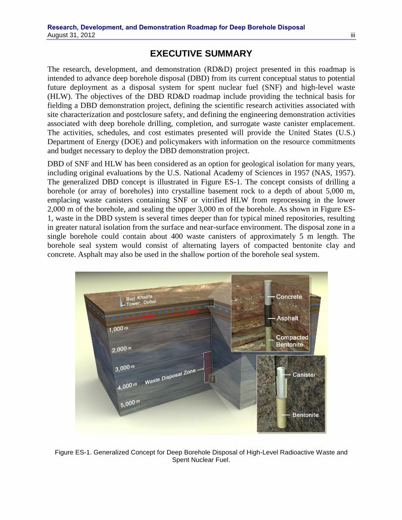
The generalized DBD concept is illustrated in Figure ES-1. The concept consists of drilling a
borehole (or array of boreholes) into crystalline basement rock to a depth of about 5,000 m,
emplacing waste canisters containing SNF or vitrified HLW from reprocessing in the lower
2,000 m of the borehole, and sealing the upper 3,000 m of the borehole. As shown in Figure ES-
1, waste in the DBD system is several times deeper than for typical mined repositories, resulting
in greater natural isolation from the surface and near-surface environment. The disposal zone in a
single borehole could contain about 400 waste canisters of approximately 5 m length. The
borehole seal system would consist of alternating layers of compacted bentonite clay and
concrete. Asphalt may also be used in the shallow portion of the borehole seal system.
Figure ES-1. Generalized Concept for Deep Borehole Disposal of High-Level Radioactive Waste and
Spent Nuclear Fuel.
Research, Development, and Demonstration Roadmap for Deep Borehole Disposal iv August 31, 2012
Numerous factors suggest that DBD of SNF and HLW is inherently safe. Several lines of
evidence indicate that groundwater at depths of several kilometers in continental crystalline
basement rocks has long residence times and low velocity. High salinity fluids have limited
potential for vertical flow because of density stratification and prevent colloidal transport of
radionuclides. Geochemically reducing conditions in the deep subsurface limit the solubility and
enhance the retardation of key radionuclides. A non-technical advantage that the deep borehole
concept may offer over a repository concept is that of facilitating incremental construction and
loading at multiple regional locations.
This DBD RD&D Roadmap is a plan for RD&D activities that will help resolve key
uncertainties about DBD and allow for a comprehensive evaluation of the potential for licensing
and deploying DBD for SNF and HLW. The full-scale field DBD demonstration presented in
this report will serve as a DBD laboratory and proof of concept and will not involve the disposal
of actual waste. The demonstration will have four primary goals: demonstrate the feasibility of
characterizing and engineering deep boreholes, demonstrate processes and operations for safe
waste emplacement down hole, confirm geologic controls over waste stability, and demonstrate
safety and practicality of licensing. There are four major RD&D tasks:
Demonstration Site Selection – This task will locate the demonstration borehole at a site that is
representative of the geology and other characteristics that would be encountered if DBD would
be implemented in the future. In addition to establishing site selection guidelines, this task also
ensures that regulatory permits for borehole construction and demonstration are in place for
implementing the DBD demonstration project.
Borehole Drilling and Construction – This task will develop a borehole design, establish
borehole requirements, implement a contract for construction of the borehole, and ensure that the
drilled and completed borehole meets requirements.
Science Thrust – This task will identify and resolve data gaps in the deep borehole geological,
hydrological, chemical, and geophysical environment that are important to postclosure safety of
the system, materials performance at depth, and construction of the disposal system. This task
uses a systematic approach to prioritize data gaps and methods for resolving them. This activity
will also perform safety analyses demonstrating the safety of the DBD concept for disposal of
SNF and HLW.
Engineering Demonstration – This task will confirm the capacity and feasibility of the DBD
concept and will include canister emplacement operations (in the borehole), canister
transference, canister stringing, and operational retrieval. This task will also include design and
fabrication of test canisters and other equipment unique to the demonstration. This task will also
provide all documentation confirming the safety, capacity, and feasibility of the DBD concept.
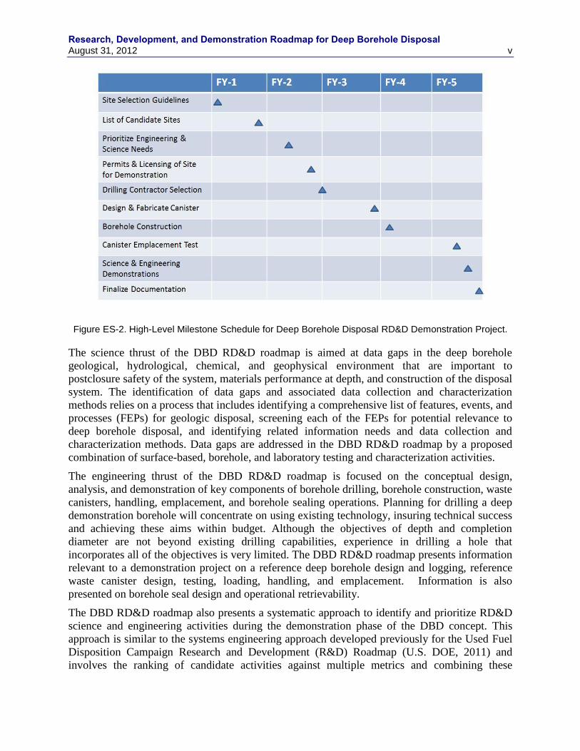
A 5-year high-level milestone schedule showing key milestones is provided in Figure ES-2.
Research, Development, and Demonstration Roadmap for Deep Borehole Disposal August 31, 2012 v
Figure ES-2. High-Level Milestone Schedule for Deep Borehole Disposal RD&D Demonstration Project.
The science thrust of the DBD RD&D roadmap is aimed at data gaps in the deep borehole
geological, hydrological, chemical, and geophysical environment that are important to
postclosure safety of the system, materials performance at depth, and construction of the disposal
system. The identification of data gaps and associated data collection and characterization
methods relies on a process that includes identifying a comprehensive list of features, events, and
processes (FEPs) for geologic disposal, screening each of the FEPs for potential relevance to
deep borehole disposal, and identifying related information needs and data collection and
characterization methods. Data gaps are addressed in the DBD RD&D roadmap by a proposed
combination of surface-based, borehole, and laboratory testing and characterization activities.
The engineering thrust of the DBD RD&D roadmap is focused on the conceptual design,
analysis, and demonstration of key components of borehole drilling, borehole construction, waste
canisters, handling, emplacement, and borehole sealing operations. Planning for drilling a deep
demonstration borehole will concentrate on using existing technology, insuring technical success
and achieving these aims within budget. Although the objectives of depth and completion
diameter are not beyond existing drilling capabilities, experience in drilling a hole that
incorporates all of the objectives is very limited. The DBD RD&D roadmap presents information
relevant to a demonstration project on a reference deep borehole design and logging, reference
waste canister design, testing, loading, handling, and emplacement. Information is also
presented on borehole seal design and operational retrievability.
The DBD RD&D roadmap also presents a systematic approach to identify and prioritize RD&D
science and engineering activities during the demonstration phase of the DBD concept. This
approach is similar to the systems engineering approach developed previously for the Used Fuel
Disposition Campaign Research and Development (R&D) Roadmap (U.S. DOE, 2011) and
involves the ranking of candidate activities against multiple metrics and combining these
Research, Development, and Demonstration Roadmap for Deep Borehole Disposal vi August 31, 2012
multiple rankings into an overall priority score using objective functions and a set of weighting
factors on the individual metric components. The prioritization of RD&D activities will also be
informed by analysis and insights gained from existing and new safety analyses, including both
qualitative and quantitative information. Such prioritization provides an important link between
DBD demonstration activities and the demonstration of postclosure safety of the DBD concept.
The legal and regulatory framework, demonstration site selection, and business management
plan are important elements of the DBD RD&D program that are also outlined in the roadmap.
Legal and regulatory issues and requirements will be addressed for the DBD demonstration
project during the site selection process. Experience has shown that acquiring permits often
results in project delays and is responsible for changes in borehole design. Since the
demonstration borehole will be unique, in terms of both size and purpose, it is important that
regulatory agencies be presented with realistic plans that take into account existing regulations.
Identifying the location for a DBD borehole will focus on a process that locates the
demonstration borehole at a site that is representative of the geology and other characteristics in
which future DBD might be carried out. Demonstration site selection should also be consistent
with principles outlined in the Blue Ribbon Commission on America‟s Nuclear Future
recommendations, including a consent-based approach that employs stakeholder outreach and is
staged, adaptive, and transparent. A sound business management plan, which will be an evolving
document that describes the key elements of business planning, outlining the processes, skills,
tools and techniques will be utilized for the DBD RD&D project. The project team will be
comprised of various organizations from National Laboratories, industry and academia.
Based on preliminary scheduling and cost analysis, implementation of the DBD RD&D plan for
the DBD demonstration project would require approximately five years and a $75 million
budget. Successful completion of a DBD demonstration project would demonstrate the feasibility
of engineering and characterizing deep disposal boreholes, demonstrate processes and operations
for safe waste emplacement in the borehole, confirm geologic, chemical, and hydrologic controls
on waste isolation, and demonstrate safety and practicality of licensing. The early phase of the
DBD demonstration project would include evaluation of existing and available boreholes within
the U.S., examination of lessons learned from deep drilling, mechanical and geologic media
issues, identification of site selection guidelines, and assessment of regional geologic conditions.
Research, Development, and Demonstration Roadmap for Deep Borehole Disposal August 31, 2012 vii
CONTENTS
CONTENTS ................................................................................................................................................ vii
1. INTRODUCTION AND BACKGROUND ....................................................................................... 1
1.1 Introduction .............................................................................................................................. 1
1.2 Background .............................................................................................................................. 2 1.2.1 Deep Borehole Disposal Concept ............................................................................... 2 1.2.2 Previous Research ....................................................................................................... 3 1.2.3 Current Status .............................................................................................................. 5
2. SCOPE AND OBJECTIVES ............................................................................................................. 7
2.1 Scope ........................................................................................................................................ 7
2.2 Summary of Objectives ............................................................................................................ 7
2.3 General Roadmap for Project Execution .................................................................................. 8
3. SCIENCE THRUST/SITE CHARACTERIZATION ...................................................................... 10
3.1 Identification of Data Gaps and Characterization Methods ................................................... 10
3.2 Geology .................................................................................................................................. 11 3.2.1 Surface-Based Characterization ................................................................................ 12 3.2.2 Borehole Characterization ......................................................................................... 14
3.3 Hydrogeology......................................................................................................................... 19 3.3.1 Drill Stem Tests of Shut-In Pressure ......................................................................... 19 3.3.2 Drill Stem Pump Tests .............................................................................................. 20 3.3.3 Packer Pump Tests .................................................................................................... 20 3.3.4 Vertical Dipole Tracer Testing.................................................................................. 21 3.3.5 Push-Pull Tracer Testing ........................................................................................... 23
3.4 Stress/Pressure Conditions and Borehole Stability ................................................................ 24 3.4.1 Borehole Caliper Log ................................................................................................ 24 3.4.2 Dipole Shear-Wave Velocity Log ............................................................................. 24
3.5 Geochemical Environment ..................................................................................................... 25 3.5.1 Fluid Samples from Packer Testing .......................................................................... 25
3.6 Thermal Effects ...................................................................................................................... 26 3.6.1 Temperature Log ....................................................................................................... 26 3.6.2 Waste Canister Mockup Electrical Heater Test ........................................................ 28
3.7 Coupled Thermal-Hydrologic-Chemical-Mechanical Behavior ............................................ 28
3.8 Engineered Material Performance .......................................................................................... 29 3.8.1 Waste Form ............................................................................................................... 29 3.8.2 Bentonite Alteration .................................................................................................. 30 3.8.3 Cement Degradation ................................................................................................. 31 3.8.4 Alternative Borehole Seals ........................................................................................ 31
3.9 Long-Term Monitoring .......................................................................................................... 32
3.10 Nuclear Criticality .................................................................................................................. 33 3.10.1 Operational Criticality Safety Assurance .................................................................. 33 3.10.2 Post Emplacement Criticality Safety Assurance ....................................................... 33
4. ENGINEERING THRUST .............................................................................................................. 35
Research, Development, and Demonstration Roadmap for Deep Borehole Disposal viii August 31, 2012
4.1 Reference Design for Demonstration ..................................................................................... 36 4.1.1 Borehole Requirements ............................................................................................. 37 4.1.2 Borehole Design ........................................................................................................ 37 4.1.3 Drilling Technology .................................................................................................. 38
4.2 Borehole Logging .................................................................................................................. 39
4.3 Borehole Construction ........................................................................................................... 40 4.3.1 Casing ....................................................................................................................... 42 4.3.2 Cementing ................................................................................................................. 44 4.3.3 Bottom Hole Assemblies .......................................................................................... 44 4.3.4 Fluid Circulation ....................................................................................................... 45 4.3.5 Monitoring ................................................................................................................ 45
4.4 Test Canisters ......................................................................................................................... 45 4.4.1 Test Canister Design Requirements .......................................................................... 45 4.4.2 Test Canister Conceptual Design .............................................................................. 47 4.4.3 Demonstration Canister Testing ................................................................................ 48 4.4.4 Additional Canister Testing for a Disposal Program ................................................ 49
4.5 Canister Loading Operations.................................................................................................. 49 4.5.1 Used Fuel Loading Operations ................................................................................. 49 4.5.2 Canister Welding Demonstration .............................................................................. 50
4.6 Waste Handling ...................................................................................................................... 50 4.6.1 Canister Transference to Shipping Cask ................................................................... 50 4.6.2 Canister Transference to Borehole ............................................................................ 51
4.7 Waste Emplacement ............................................................................................................... 51 4.7.1 Waste Canister String Demonstration ....................................................................... 52 4.7.2 Emplacement Grout Demonstration .......................................................................... 52 4.7.3 Setting Bridge Plugs.................................................................................................. 52 4.7.4 Operational Radiological Monitoring ....................................................................... 53
4.8 Seal Design and Closure ........................................................................................................ 54 4.8.1 Seal Emplacement Operations .................................................................................. 54 4.8.2 Seal Integrity Testing ................................................................................................ 56
4.9 Operational Retrievability ...................................................................................................... 56
5. IDENTIFICATION & PRIORITIZATION OF RESEARCH AND DEVELOPMENT
NEEDS ............................................................................................................................................. 58
5.1 Systematic Approach ............................................................................................................. 58
5.2 Identification of Potential RD&D Needs ............................................................................... 58 5.2.1 Objectives of the DBD Demonstration ..................................................................... 58 5.2.2 Identification and Characterization of Science and Engineering Activities.............. 59
5.3 Evaluation and Prioritization of RD&D Activities ................................................................ 60 5.3.1 Identification of Metrics ............................................................................................ 60 5.3.2 Evaluation of Science and Engineering Activities Supporting Deep Borehole
Disposal Demonstration ............................................................................................ 63 5.3.3 Scoring and Prioritization ......................................................................................... 64
6. DEMONSTRATION OF SAFETY .................................................................................................. 66
6.1 Postclosure Safety .................................................................................................................. 66 6.1.1 UFD R&D Road Map ............................................................................................... 66 6.1.2 Existing Postclosure Analyses in Support of Activity Prioritization ........................ 71
Research, Development, and Demonstration Roadmap for Deep Borehole Disposal August 31, 2012 ix
7. LEGAL AND REGULATORY FRAMEWORK ............................................................................ 75
7.1 Demonstration ........................................................................................................................ 75 7.1.1 Local, State, and Federal Permits .............................................................................. 75 7.1.2 Drilling Permits ......................................................................................................... 75 7.1.3 Air Quality Permits ................................................................................................... 75 7.1.4 Land/Water Use Permits ........................................................................................... 75
7.2 National Environmental Policy Act Compliance ................................................................... 75
8. SITE SELECTION/DEMONSTRATION PROJECT ...................................................................... 77
8.1 Siting Process ......................................................................................................................... 77
8.2 Site Selection Guidelines ....................................................................................................... 78 8.2.1 Technical Guidelines Related to the Science Thrust ................................................. 78 8.2.2 Technical Guidelines Related to the Engineering Thrust .......................................... 80
8.3 Stakeholder Outreach ............................................................................................................. 80
9. BUSINESS MANAGEMENT ......................................................................................................... 82
9.1 Project Team and Organizational Structure ........................................................................... 82
9.2 Project Execution and Management Plan............................................................................... 82
9.3 Work Breakdown Structure.................................................................................................... 82
9.4 Cost Management .................................................................................................................. 82
9.5 Project Schedule ..................................................................................................................... 83
9.6 Communications Management............................................................................................... 83
9.7 Project Risk Assessment ........................................................................................................ 83
9.8 Quality Assurance .................................................................................................................. 83
10. LONG-TERM USE AND MAINTENANCE .................................................................................. 84
11. SUMMARY ..................................................................................................................................... 85
12. REFERENCES ................................................................................................................................. 87
Appendix A. FEPS and Science Thrust Information Needs and Characterization Methods ........ A-1
Appendix B. Activities Relevant to Deep Borehole Demonstration ............................................ B-1
Appendix C. Importance of FEPS to Deep Borehole Disposal from UFD R&D Road Map ....... C-1
Appendix D. WBS Chart .............................................................................................................. D-1
Appendix E. Preliminary Cost Estimate ...................................................................................... E-1
Appendix F. DBD Demonstration Project Schedule ..................................................................... F-1
Research, Development, and Demonstration Roadmap for Deep Borehole Disposal x August 31, 2012
FIGURES
Figure ES-1. Generalized Concept for Deep Borehole Disposal of High-Level Radioactive Waste
and Spent Nuclear Fuel. ............................................................................................................... iii
Figure ES-2. High-Level Milestone Schedule for Deep Borehole Disposal RD&D Demonstration
Project. .......................................................................................................................................... v
Figure 1-1. Generalized Concept for Deep Borehole Disposal of High-Level Radioactive Waste
and Spent Nuclear Fuel. ................................................................................................................ 3
Figure 2-1. High-Level Milestone Schedule for Deep Borehole Disposal RD&D Demonstration
Project. .......................................................................................................................................... 9
Figure 3-1. Example FMI log with Interpreted Fracture Orientations. ....................................................... 17
Figure 3-2. Schematic Diagram of the Vertical Dipole Tracer Test Configuration (from Roos
2009). .......................................................................................................................................... 22
Figure 3-3. Schematic Diagram of a Push-Pull Tracer Test Configuration. ............................................... 23
Figure 3-4. Example Borehole Temperature Log with Plots of Vertical Temperature Gradient,
Measured Values of Thermal Conductivity, and Calculated Heat Flux. (Source:
http://www.geophysik.rwth-aachen.de/Forschung/Geothermik/kola/kola-
1.htm#CONTENT). .................................................................................................................... 28
Figure 3-5. Schematic of Borehole Seals Components (from Herrick et al., 2011). .................................. 29
Figure 4-1. Relationship between Depth and Diameter Generated by Actual Practice (from
Beswick, 2008). .......................................................................................................................... 35
Figure 4-2. Reference Borehole Design (from Arnold et al., 2011). .......................................................... 38
Figure 4-3. Reference Disposal Borehole Design (from Arnold et al., 2011). ........................................... 43
Research, Development, and Demonstration Roadmap for Deep Borehole Disposal August 31, 2012 xi
TABLES
Table 4-1. Borehole Logging and Testing. ................................................................................................. 40
Table 4-2. Borehole Casing Specifications. ................................................................................................ 44
Table 5-1. Example Metrics and Scoring for Prioritizing Science Activities. ............................................ 61
Table 5-2. Example Evaluation and Prioritization of Potential Science Activities. ................................... 63
Table 6-1. UFD R&D Road Map Priorities for DBD. ................................................................................ 67
Table 6-2. Synopsis of the Results of Cross-Cutting R&D Issues. ............................................................. 67
Table 6-3. FEP Importance to Deep Borehole Disposal Safety Case by Priority. ...................................... 68
Table A-1. Comprehensive FEPs List with likely Screening Decision, Effort to support Decision,
and Supporting Characterization Needs. (Based on YMP Features, Events, and
Processes List and Screening Decisions Listed by FEP Number: Sandia National
Laboratories 2008, Table 7.1.). ................................................................................................. A-1
Table A-2. Characterization Methods supporting Deep Borehole FEPs. ............................................... A-21
Table B-1. Potential Activities Supporting the Deep Borehole Demonstration and Categorization. ....... B-1
Table C-1. Synopsis of FEPs Priority Ranking for the Deep Borehole Natural System. ......................... C-1
Table C-2. Synopsis of FEPs Priority Ranking for the Deep Borehole Engineered System. ................... C-2
Table E-1. Preliminary Cost Estimates. .................................................................................................... E-1
Research, Development, and Demonstration Roadmap for Deep Borehole Disposal xii August 31, 2012
ACRONYMS
AI acoustic impedance
API American Petroleum Institute
ASME American Society of Mechanical Engineers
AVO amplitude variation offset
BHA bottom hole assembly
BOPE blow-out prevention equipment
BRC Blue Ribbon Commission
BWR boiling water reactor
CSH calcium-silicate-hydrate
DBD deep borehole disposal
DOE Department of Energy
DRZ disturbed rock zone
DST drill stem testing
EIS environmental impact statement
FEP features, events and processes
FMI formation micro-imager
GIS geographical information system
HLW high-level waste
IADC International Association of Drilling Contractors
ID inside diameter
KTB Kontinentales Tiefbohrprogramm der Bundesrepublik, Deutschland
LCM lost circulation material
LEU low enriched uranium
LLNL Lawrence Livermore National Laboratory
MIT Massachusetts Institute of Technology
MWD measurements while drilling
NAS National Academy of Sciences
NEPA National Environmental Policy Act
OD outside diameter
Research, Development, and Demonstration Roadmap for Deep Borehole Disposal August 31, 2012 xiii
PA performance assessment
PWR pressurized water reactor
QA quality assurance
QC quality control
R&D research and development
RD&D research, development, and demonstration
SNF spent nuclear fuel
SNL Sandia National Laboratories
SP spontaneous potential
U.S. United States
UFDC Used Fuel Disposition Campaign
WBS work breakdown structure
WOB weight-on-bit


Research, Development, and Demonstration Roadmap for Deep Borehole Disposal August 31, 2012 1

Research, Development, and Demonstration Roadmap for Deep Borehole Disposal August 31, 2012 1
RESEARCH, DEVELOPMENT, AND DEMONSTRATION PLAN FOR DEEP BOREHOLE DISPOSAL
1. INTRODUCTION AND BACKGROUND
1.1 Introduction
The United States (U.S.) has focused its past efforts on disposing spent nuclear fuel (SNF) and
high-level waste (HLW) in a geologic repository. SNF in this report refers to used nuclear fuel
for which a final decision has been made for geologic disposal. More recently, the U.S.
Department of Energy (DOE) has been investigating Deep Borehole Disposal (DBD) as an
alternative for disposal of SNF and HLW because of a recommendation by the Blue Ribbon
Commission (BRC). The Blue Ribbon Commission (BRC 2012, p. 30) recommended “further
RD&D to help resolve some of the current uncertainties about deep borehole disposal and to
allow for a more comprehensive (and conclusive) evaluation of the potential practicality of
licensing and deploying this approach, particularly as a disposal alternative for certain forms of
waste that have essentially no potential for re-use.”
Deep Borehole Disposal of SNF and HLW has been considered as an option for geological
isolation for many years, including original evaluations by the U.S. National Academy of
Sciences in 1957 (NAS 1957). Reconsideration of the DBD option for SNF, HLW, and excess
fissile materials has occurred periodically over the last several decades. More recently, advances
in drilling technology that have decreased the cost and increased the reliability of drilling large-
diameter boreholes to a depth of several kilometers have increased the feasibility of DBD.
This DBD Research, Development, and Demonstration (RD&D) Roadmap is a plan for RD&D
activities that will help resolve key uncertainties about DBD and allow for a comprehensive
evaluation of the potential for licensing and deploying DBD for SNF and HLW. This roadmap is
a “living” plan and will be revised to update the prioritization and status of activities and RD&D
needs as progress is made or as necessary to reflect improved understanding. The full-scale DBD
demonstration presented will serve as a DBD laboratory and proof of concept and will not
involve the disposal of actual radioactive waste or materials. The demonstration will have four
primary goals: demonstrate the feasibility of characterizing and engineering deep boreholes,
demonstrate processes and operations for safe waste emplacement down hole, confirm geologic
controls over waste stability, and demonstrate safety and practicality of DBD as a disposal
concept.
The DBD RD&D Plan documented in this report distinguishes between a DBD Demonstration
Project and a broader DBD Program. A DBD Demonstration Project is a key early element of a
DBD Program and is focused on demonstrating the viability of the DBD concept. A DBD
Program consists of all elements necessary to establish proof of concept of DBD and
demonstrate its implementation and safety. This RD&D Plan focuses on activities for a DBD
Demonstration Project, but also provides more general information on the additional RD&D
activities needed for success of a DBD Program. For example, a more detailed plan is provided
for the activities supporting selection of a site for a DBD Demonstration Project; whereas, a
more general discussion is included for activities supporting site selection of an actual deep
borehole waste disposal facility. In general, science thrust activities play a more important role in
Research, Development, and Demonstration Roadmap for Deep Borehole Disposal
2 August 31, 2012
the early phases of a DBD Demonstration Project, and engineering thrust and engineering
demonstration activities are given more emphasis in later phases of a DBD Program.
1.2 Background
Borehole disposal has long been recognized as a means for isolating hazardous materials from
the environment. It is widely and routinely used for the disposal of liquid hazardous waste,
particularly within the petroleum industry. As noted above, deep borehole disposal has been
recommended for consideration as an alternative disposal method for SNF and HLW since the
1950s. The DBD concept addresses the need for isolation of these wastes from the biosphere,
from potential inadvertent human intrusion, and with regard to security and non-proliferation of
nuclear weapons.
Although relatively simple in concept, actual implementation of deep borehole disposal of SNF
and HLW requires assessment of several elements of the disposal system that have yet to be done
or attempted, the major element being the drilling of a borehole of sufficient diameter and depth.
Several previous studies have evaluated various components of the system with regard to
feasibility and made recommendations for technologies to be employed.
1.2.1 Deep Borehole Disposal Concept
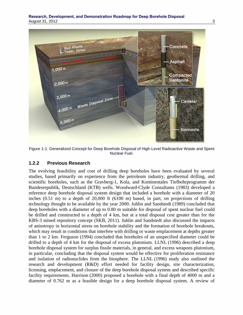
The generalized DBD concept is illustrated in Figure 1-1. The concept consists of drilling a
borehole (or array of boreholes) into crystalline basement rock to a depth of about 5,000 m,
emplacing waste canisters containing SNF or vitrified HLW from reprocessing in the lower
2,000 m of the borehole, and sealing the upper 3,000 m of the borehole. As shown in Figure 1-1,
waste in the DBD system is several times deeper than for typical mined repositories, resulting in
greater natural isolation from the surface and near-surface environment. The disposal zone in a
single borehole could contain about 400 waste canisters of approximately 5 m length. The
borehole seal system would consist of alternating layers of compacted bentonite clay and
concrete. Asphalt may also be used in the shallow portion of the borehole seal system.
Numerous factors suggest that DBD of SNF and HLW is inherently safe. Several lines of
evidence indicate that groundwater at depths of several kilometers in continental crystalline
basement rocks has long residence times and low velocity. High salinity fluids have limited
potential for vertical flow because of density stratification and prevent colloidal transport of
radionuclides. Geochemically reducing conditions in the deep subsurface limit the solubility and
enhance the retardation of key radionuclides. A non-technical advantage that the deep borehole
concept may offer over a repository concept is that of facilitating incremental construction and
loading at multiple regional locations. Drilling and testing at a demonstration borehole location
will not include any used nuclear materials or high level nuclear waste in the demonstration.
Siting of a demonstration borehole need not include all the regulatory compliance issues
associated with siting a repository for nuclear materials disposal.
Research, Development, and Demonstration Roadmap for Deep Borehole Disposal August 31, 2012 3
Figure 1-1. Generalized Concept for Deep Borehole Disposal of High-Level Radioactive Waste and Spent Nuclear Fuel.
1.2.2 Previous Research
The evolving feasibility and cost of drilling deep boreholes have been evaluated by several
studies, based primarily on experience from the petroleum industry, geothermal drilling, and
scientific boreholes, such as the Gravberg-1, Kola, and Kontinentales Tiefbohrprogramm der
Bundesrepublik, Deutschland (KTB) wells. Woodward-Clyde Consultants (1983) developed a
reference deep borehole disposal system design that included a borehole with a diameter of 20
inches (0.51 m) to a depth of 20,000 ft (6100 m) based, in part, on projections of drilling
technology thought to be available by the year 2000. Juhlin and Sandstedt (1989) concluded that
deep boreholes with a diameter of up to 0.80 m suitable for disposal of spent nuclear fuel could
be drilled and constructed to a depth of 4 km, but at a total disposal cost greater than for the
KBS-3 mined repository concept (SKB, 2011). Juhlin and Sandstedt also discussed the impacts
of anisotropy in horizontal stress on borehole stability and the formation of borehole breakouts,
which may result in conditions that interfere with drilling or waste emplacement at depths greater
than 1 to 2 km. Ferguson (1994) concluded that boreholes of an unspecified diameter could be
drilled to a depth of 4 km for the disposal of excess plutonium. LLNL (1996) described a deep
borehole disposal system for surplus fissile materials, in general, and excess weapons plutonium,
in particular, concluding that the disposal system would be effective for proliferation resistance
and isolation of radionuclides from the biosphere. The LLNL (1996) study also outlined the
research and development (R&D) effort needed for facility design, site characterization,
licensing, emplacement, and closure of the deep borehole disposal system and described specific
facility requirements. Harrison (2000) proposed a borehole with a final depth of 4000 m and a
diameter of 0.762 m as a feasible design for a deep borehole disposal system. A review of
Research, Development, and Demonstration Roadmap for Deep Borehole Disposal
4 August 31, 2012
previous work on deep borehole disposal by Nirex (2004) generally supports the feasibility of
constructing the necessary deep boreholes. A more systematic analysis of borehole diameter
versus depth in completed boreholes by Beswick (2008) suggests that a borehole diameter of
0.30 m is readily achievable to a depth of 5000 m and a diameter of 0.50 m may be achievable,
but that diameters of greater than 0.50 m are, in practice, not obtained with current drilling
technology. Beswick (2008) also emphasizes the constraints of borehole stability at depths of
several kilometers.
Multi-lateral boreholes are routinely used in the petroleum industry and a fanned array of
inclined or horizontal boreholes from a central borehole has been suggested for a deep borehole
disposal system by Chapman and Gibb (2003) and Gibbs (2010). A multi-lateral borehole system
could potentially reduce drilling costs, limit the surface footprint of a borehole disposal program,
and would result in a single seal system in the central access borehole. However, a multi-lateral
system increases the complexity of the waste emplacement process and is not recommended by
Beswick (2008).
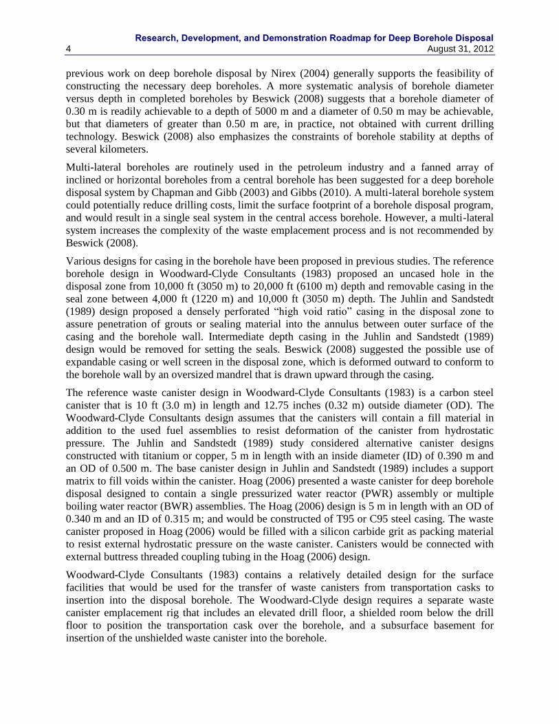
Various designs for casing in the borehole have been proposed in previous studies. The reference
borehole design in Woodward-Clyde Consultants (1983) proposed an uncased hole in the
disposal zone from 10,000 ft (3050 m) to 20,000 ft (6100 m) depth and removable casing in the
seal zone between 4,000 ft (1220 m) and 10,000 ft (3050 m) depth. The Juhlin and Sandstedt
(1989) design proposed a densely perforated “high void ratio” casing in the disposal zone to
assure penetration of grouts or sealing material into the annulus between outer surface of the
casing and the borehole wall. Intermediate depth casing in the Juhlin and Sandstedt (1989)
design would be removed for setting the seals. Beswick (2008) suggested the possible use of
expandable casing or well screen in the disposal zone, which is deformed outward to conform to
the borehole wall by an oversized mandrel that is drawn upward through the casing.
The reference waste canister design in Woodward-Clyde Consultants (1983) is a carbon steel
canister that is 10 ft (3.0 m) in length and 12.75 inches (0.32 m) outside diameter (OD). The
Woodward-Clyde Consultants design assumes that the canisters will contain a fill material in
addition to the used fuel assemblies to resist deformation of the canister from hydrostatic
pressure. The Juhlin and Sandstedt (1989) study considered alternative canister designs
constructed with titanium or copper, 5 m in length with an inside diameter (ID) of 0.390 m and
an OD of 0.500 m. The base canister design in Juhlin and Sandstedt (1989) includes a support
matrix to fill voids within the canister. Hoag (2006) presented a waste canister for deep borehole
disposal designed to contain a single pressurized water reactor (PWR) assembly or multiple
boiling water reactor (BWR) assemblies. The Hoag (2006) design is 5 m in length with an OD of
0.340 m and an ID of 0.315 m; and would be constructed of T95 or C95 steel casing. The waste
canister proposed in Hoag (2006) would be filled with a silicon carbide grit as packing material
to resist external hydrostatic pressure on the waste canister. Canisters would be connected with
external buttress threaded coupling tubing in the Hoag (2006) design.
Woodward-Clyde Consultants (1983) contains a relatively detailed design for the surface
facilities that would be used for the transfer of waste canisters from transportation casks to
insertion into the disposal borehole. The Woodward-Clyde design requires a separate waste
canister emplacement rig that includes an elevated drill floor, a shielded room below the drill
floor to position the transportation cask over the borehole, and a subsurface basement for
insertion of the unshielded waste canister into the borehole.
Research, Development, and Demonstration Roadmap for Deep Borehole Disposal August 31, 2012 5
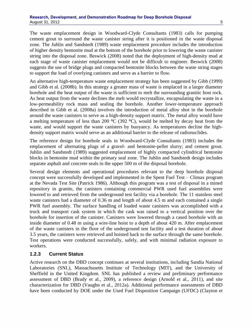
The waste emplacement design in Woodward-Clyde Consultants (1983) calls for pumping
cement grout to surround the waste canister string after it is positioned in the waste disposal
zone. The Juhlin and Sandstedt (1989) waste emplacement procedure includes the introduction
of higher density bentonite mud at the bottom of the borehole prior to lowering the waste canister
string into the disposal zone. Beswick (2008) noted that the deployment of high-density mud at
each stage of waste canister emplacement would not be difficult to engineer. Beswick (2008)
suggests the use of bridge plugs and compacted bentonite blocks between the waste string stages
to support the load of overlying canisters and serve as a barrier to flow.
An alternative high-temperature waste emplacement strategy has been suggested by Gibb (1999)
and Gibb et al. (2008b). In this strategy a greater mass of waste is emplaced in a larger diameter
borehole and the heat output of the waste is sufficient to melt the surrounding granitic host rock.
As heat output from the waste declines the melt would recrystallize, encapsulating the waste in a
low-permeability rock mass and sealing the borehole. Another lower-temperature approach
described in Gibb et al. (2008a) involves the introduction of metal alloy shot in the borehole
around the waste canisters to serve as a high-density support matrix. The metal alloy would have
a melting temperature of less than 200 ºC (392 ºC), would be melted by decay heat from the
waste, and would support the waste canisters by buoyancy. As temperatures decline the high-
density support matrix would serve as an additional barrier to the release of radionuclides.
The reference design for borehole seals in Woodward-Clyde Consultants (1983) includes the
emplacement of alternating plugs of a gravel- and bentonite-pellet slurry; and cement grout.
Juhlin and Sandstedt (1989) suggested emplacement of highly compacted cylindrical bentonite
blocks in bentonite mud within the primary seal zone. The Juhlin and Sandstedt design includes
separate asphalt and concrete seals in the upper 500 m of the disposal borehole.
Several design elements and operational procedures relevant to the deep borehole disposal
concept were successfully developed and implemented in the Spent Fuel Test – Climax program
at the Nevada Test Site (Patrick 1986). Although this program was a test of disposal in a mined
repository in granite, the canisters containing commercial PWR used fuel assemblies were
lowered to and retrieved from the underground test facility via a borehole. The 11 stainless steel
waste canisters had a diameter of 0.36 m and length of about 4.5 m and each contained a single
PWR fuel assembly. The surface handling of loaded waste canisters was accomplished with a
truck and transport cask system in which the cask was raised to a vertical position over the
borehole for insertion of the canister. Canisters were lowered through a cased borehole with an
inside diameter of 0.48 m using a wire-line hoist to a depth of about 420 m. After emplacement
of the waste canisters in the floor of the underground test facility and a test duration of about
3.5 years, the canisters were retrieved and hoisted back to the surface through the same borehole.
Test operations were conducted successfully, safely, and with minimal radiation exposure to
workers.
1.2.3 Current Status
Active research on the DBD concept continues at several institutions, including Sandia National
Laboratories (SNL), Massachusetts Institute of Technology (MIT), and the University of
Sheffield in the United Kingdom. SNL has published a review and preliminary performance
assessment of DBD (Brady et al., 2009), a reference design (Arnold et al., 2011), and site
characterization for DBD (Vaughn et al., 2012a). Additional performance assessments of DBD
have been conducted by DOE under the Used Fuel Disposition Campaign (UFDC) (Clayton et

Research, Development, and Demonstration Roadmap for Deep Borehole Disposal
6 August 31, 2012
al, 2011 and Vaughn et al, 2012b). MIT has supported several graduate students over the past
decade in the area of DBD (e.g., Anderson 2004, Hoag 2006, Sizer 2006, Moulton 2008, Gibbs
2010, and Bates et al., 2011). Research at MIT has included engineering analyses of DBD,
exploration of alternative engineering designs, system studies, and supporting laboratory
experimental work. Research at the University of Sheffield has been directed at thermal
management of waste disposal in deep boreholes to create seals via melting of the host rock and
melting of a supporting metal alloy (Gibb et al., 2008b and Gibb et al., 2008a).
Research, Development, and Demonstration Roadmap for Deep Borehole Disposal August 31, 2012 7
2. SCOPE AND OBJECTIVES
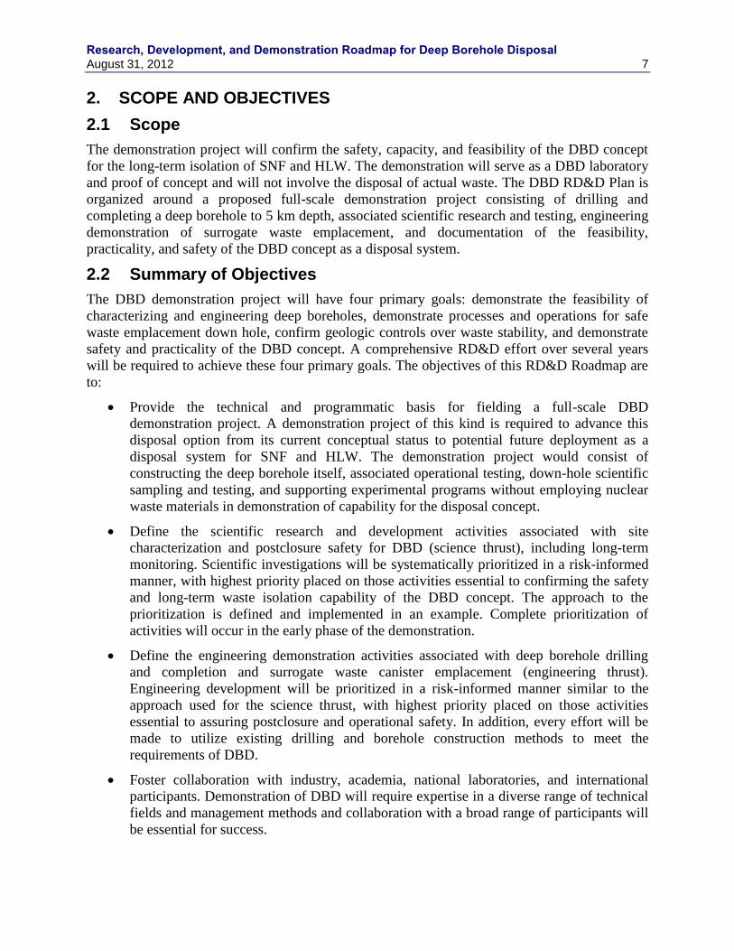
2.1 Scope
The demonstration project will confirm the safety, capacity, and feasibility of the DBD concept
for the long-term isolation of SNF and HLW. The demonstration will serve as a DBD laboratory
and proof of concept and will not involve the disposal of actual waste. The DBD RD&D Plan is
organized around a proposed full-scale demonstration project consisting of drilling and
completing a deep borehole to 5 km depth, associated scientific research and testing, engineering
demonstration of surrogate waste emplacement, and documentation of the feasibility,
practicality, and safety of the DBD concept as a disposal system.
2.2 Summary of Objectives
The DBD demonstration project will have four primary goals: demonstrate the feasibility of
characterizing and engineering deep boreholes, demonstrate processes and operations for safe
waste emplacement down hole, confirm geologic controls over waste stability, and demonstrate
safety and practicality of the DBD concept. A comprehensive RD&D effort over several years
will be required to achieve these four primary goals. The objectives of this RD&D Roadmap are
to:
Provide the technical and programmatic basis for fielding a full-scale DBD
demonstration project. A demonstration project of this kind is required to advance this
disposal option from its current conceptual status to potential future deployment as a
disposal system for SNF and HLW. The demonstration project would consist of
constructing the deep borehole itself, associated operational testing, down-hole scientific
sampling and testing, and supporting experimental programs without employing nuclear
waste materials in demonstration of capability for the disposal concept.
Define the scientific research and development activities associated with site
characterization and postclosure safety for DBD (science thrust), including long-term
monitoring. Scientific investigations will be systematically prioritized in a risk-informed
manner, with highest priority placed on those activities essential to confirming the safety
and long-term waste isolation capability of the DBD concept. The approach to the
prioritization is defined and implemented in an example. Complete prioritization of
activities will occur in the early phase of the demonstration.
Define the engineering demonstration activities associated with deep borehole drilling
and completion and surrogate waste canister emplacement (engineering thrust).
Engineering development will be prioritized in a risk-informed manner similar to the
approach used for the science thrust, with highest priority placed on those activities
essential to assuring postclosure and operational safety. In addition, every effort will be
made to utilize existing drilling and borehole construction methods to meet the
requirements of DBD.
Foster collaboration with industry, academia, national laboratories, and international
participants. Demonstration of DBD will require expertise in a diverse range of technical
fields and management methods and collaboration with a broad range of participants will
be essential for success.
Research, Development, and Demonstration Roadmap for Deep Borehole Disposal
8 August 31, 2012
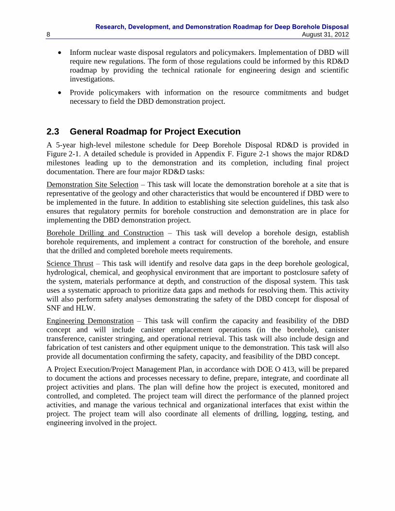
Inform nuclear waste disposal regulators and policymakers. Implementation of DBD will
require new regulations. The form of those regulations could be informed by this RD&D
roadmap by providing the technical rationale for engineering design and scientific
investigations.
Provide policymakers with information on the resource commitments and budget
necessary to field the DBD demonstration project.
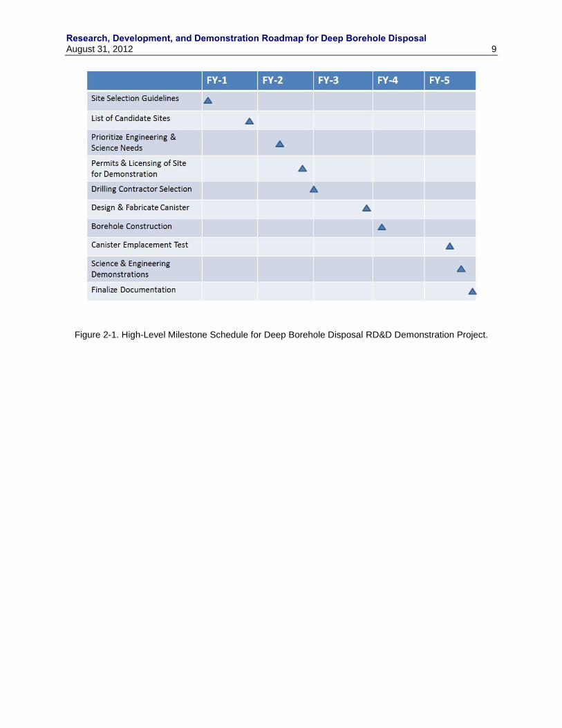
2.3 General Roadmap for Project Execution
A 5-year high-level milestone schedule for Deep Borehole Disposal RD&D is provided in
Figure 2-1. A detailed schedule is provided in Appendix F. Figure 2-1 shows the major RD&D
milestones leading up to the demonstration and its completion, including final project
documentation. There are four major RD&D tasks:
Demonstration Site Selection – This task will locate the demonstration borehole at a site that is
representative of the geology and other characteristics that would be encountered if DBD were to
be implemented in the future. In addition to establishing site selection guidelines, this task also
ensures that regulatory permits for borehole construction and demonstration are in place for
implementing the DBD demonstration project.
Borehole Drilling and Construction – This task will develop a borehole design, establish
borehole requirements, and implement a contract for construction of the borehole, and ensure
that the drilled and completed borehole meets requirements.
Science Thrust – This task will identify and resolve data gaps in the deep borehole geological,
hydrological, chemical, and geophysical environment that are important to postclosure safety of
the system, materials performance at depth, and construction of the disposal system. This task
uses a systematic approach to prioritize data gaps and methods for resolving them. This activity
will also perform safety analyses demonstrating the safety of the DBD concept for disposal of
SNF and HLW.
Engineering Demonstration – This task will confirm the capacity and feasibility of the DBD
concept and will include canister emplacement operations (in the borehole), canister
transference, canister stringing, and operational retrieval. This task will also include design and
fabrication of test canisters and other equipment unique to the demonstration. This task will also
provide all documentation confirming the safety, capacity, and feasibility of the DBD concept.
A Project Execution/Project Management Plan, in accordance with DOE O 413, will be prepared
to document the actions and processes necessary to define, prepare, integrate, and coordinate all
project activities and plans. The plan will define how the project is executed, monitored and
controlled, and completed. The project team will direct the performance of the planned project
activities, and manage the various technical and organizational interfaces that exist within the
project. The project team will also coordinate all elements of drilling, logging, testing, and
engineering involved in the project.
Research, Development, and Demonstration Roadmap for Deep Borehole Disposal August 31, 2012 9
Figure 2-1. High-Level Milestone Schedule for Deep Borehole Disposal RD&D Demonstration Project.
Research, Development, and Demonstration Roadmap for Deep Borehole Disposal
10 August 31, 2012
3. SCIENCE THRUST/SITE CHARACTERIZATION
The science thrust of the DBD RD&D roadmap is aimed at data gaps in the deep borehole
geological, hydrological, chemical, and geophysical environment that are important to
postclosure safety of the system, materials performance at depth, and construction of the disposal
system.
3.1 Identification of Data Gaps and Characterization Methods
The identification of data gaps and associated data collection and characterization methods relies
on a process that includes identifying a comprehensive list of features, events, and processes
(FEPs) for geologic disposal, screening each of the FEPs for potential relevance to deep borehole
disposal, and identifying related information needs and data collection and characterization
methods. The overall process is summarized here, with a comprehensive FEPs list, screening
results, and identified information needs presented in Appendix A.
Various programs in the U.S. and other nations have compiled exhaustive lists of FEPs for mined
geologic disposal. The FEP list from the Yucca Mountain license application was adopted by
Brady et al. (2009) as a reasonable starting point for evaluation of FEPs and their potential
relevance to deep borehole disposal of radioactive wastes. Each of the 374 FEPs on the Yucca
Mountain FEP list was considered (screened) by Brady et al. (2009) and the results are used
herein as a starting point for identifying data and characterization needs. Table A-1 in Appendix
A summarizes the initial screening evaluation and decision for each FEP (whether a FEP is likely
to need to be included in or excluded from a full safety analysis for deep borehole disposal) and
also includes a qualitative estimate of the level of effort likely to be required to provide a robust
basis for the screening of the FEP. The FEPs that are highlighted in Table A-1 represent those
FEPs (107 FEPs) currently considered particularly important to DBD (Brady et al., 2009). For
excluded FEPs listed within Table A-1, 1 means the technical or regulatory basis is readily
available and all that is needed is documentation; 2 means new technical work likely is needed,
and 3 indicates a potentially significant amount of work is needed to support the screening
decision to exclude the FEP. For included FEPs in Table A-1, 1 indicates that this is a normal
part of modeling, 2 indicates that this is a significant aspect of the modeling, and 3 indicates
possible modeling challenges. Notes entered in the “Estimated DBD Level of Effort” column
provide clarification about how the FEP may need to be considered for deep borehole disposal.
Each of the FEPs in Table A-1 was evaluated for information needs and if applicable assigned
characterization techniques for obtaining that information. Table A-2 presents a summary of this
evaluation showing each of the identified characterization techniques and the specific FEPs that
they address. The information is also presented in the master FEPs list, Table A-1, showing the
characterization methods that support each of the FEPs. As seen in Tables A-1 and A-2, a total of
24 characterization methods were identified addressing 89 FEPs of which 63 were identified in
Brady et al. (2009) as key FEPs for DBD The remainder of the FEPs in Table A-1 is addressed
using information not coming from the characterization methods identified. Each of these
characterization techniques in addition to other methods of data collection and their application
to DBD are described in this section. As shown in Table A-2, a number of the characterization
methods address many of the same FEPs and information needs. This apparent redundancy can
provide cross-checking of the data collected or it may be possible to evaluate the list of
characterization methods and the data they produce to remove the redundancy, resulting in a
shorter list. The focus in this section has been to be comprehensive and further culling of the
Research, Development, and Demonstration Roadmap for Deep Borehole Disposal August 31, 2012 11
identified methods will be done during the initial phases of the DBD demonstration project. The
characterization methods and information needs resulting from the FEPs evaluation described
above are described next.
3.2 Geology
Geological characterization includes lithology, mineralogy, physical properties, fracture
characterization, and delineation of faults and structures in the subsurface. Significant
characterization information relevant to the suitability of a particular site may be obtained from
surface-based methods prior to drilling. These are generally standard geophysical and logging
methods from the petroleum and mineral exploration industries.
Understanding the stratigraphy of a potential DBD site is important to 1) locate the crystalline
basement rock, 2) identify features such as folds, igneous intrusions, and salt domes, and 3)
locate Quaternary-age volcanic rocks or igneous intrusions. Direct release of radionuclides to the
biosphere could occur if the magmatic conduit for a volcanic eruption intersected the waste
disposal zone. The presence of igneous rocks of Quaternary age at the surface or intersected by
the borehole would indicate a potentially significant probability of future volcanic activity and
associated impacts on repository performance.
Basic lithological information is central to interpreting the geology and geologic history of the
site. Petrographic data (i.e., mineralogy and texture of rock types) would augment geological
interpretation and provide information relevant to groundwater flow and radionuclide transport,
such as porosity and sorption characteristics. Mineralogy would also identify any occurrences of
potentially economically valuable minerals. Characterization of lithology assists in determination
on parameters needed for flow, transport, and/or heat transport simulations. For example,
average rock density is used in radionuclide transport modeling for adsorbing radionuclides and
in heat transport simulations. Other important parameters that can be estimated based on
lithology or mineralogy include sorption coefficients, bulk density, mechanical properties, and
thermal properties.
Understanding faults or highly fractured zones is critical to identifying interconnected zones of
high permeability from the waste disposal zone to the surface or shallow subsurface. A high-
permeability pathway from the waste disposal zone to the shallow subsurface could conduct
significant groundwater flow and associated radionuclide transport, particularly by thermally
driven flow during the period of high heat output by the waste. In addition, it is important to
evaluate the possibility of these preferential pathways intersecting boreholes at depth. The
location, displacement, and orientation of faults exposed at the surface should be identified.
Faults that are exposed at the surface often extend into the deep subsurface. Finally, it is
important to exclude the possibility of igneous rock in the waste disposal zone overthrusting
above sedimentary rocks.
It is also important to analyze fault displacement history. Any active faults near the site would be
relevant to the DBD system with regard to seismic risk, tectonic stability, and potential for
displacement of the borehole and damage to waste canisters. Potential evidence of Quaternary-
age activity along faults should be analyzed accordingly.
Fracture network as a function of depth should be characterized. Fracture orientations and cross-
cutting relationships may be useful in reconstructing the structural and tectonic history of
crystalline basement rocks. Information on fracture network geometry, fracture aperture, and
Research, Development, and Demonstration Roadmap for Deep Borehole Disposal
12 August 31, 2012
fracture filling may have implications for the interconnectivity of the fracture network and bulk
permeability of the system.
Characterization of fractures will also assist with understanding the physical and hydrogeological
properties of the system. Fracture aperture measurements can be used to estimate the flow
porosity of the host rock. Identification of open fractures and fracture zones will help with
understanding water quality; groundwater samples would be more likely obtained from setting
packers and sampling in zones that contain open fractures. Hydraulic packer testing and push-
pull tracer testing would also be more successful in borehole intervals that have open fractures.
3.2.1 Surface-Based Characterization
Surface-based characterization is conducted either on the ground surface or via airborne surveys
to better understand subsurface stratigraphy and structures. These surveys measure either
naturally occurring anomalies (gravitational or magnetic), variations in the electrical resistivity
of the subsurface, or can measure anthropogenic alterations (such as mines or other excavations)
from a seismic source. Surface geological mapping, 3D seismic imaging, gravity and magnetic
surveying, and electrical resistivity profiling methods are examples of surface based
characterization. More detailed descriptions of these methods are presented in Vaughn et al.
(2012a).
In general, surface-based characterization is the first step to confirming that a site is potentially
suitable. For example, determining the location of the basement rock using surface geological
mapping and geophysical profiles will help determine if the basement rock is deep enough to
make the site suitable for DBD. It can also be used to evaluate the likelihood that there will be
transmissive pathways from the waste disposal zone to the surface or shallow subsurface. If it is
decided that a site is potentially suitable, surface-based characterization can help guide the
drilling program (e.g., estimate how deep to drill the well). During and after well drilling,
borehole based characterization can be used for more detailed site characterization. In addition,
some features (e.g., mineralogy, porosity, and other petrophysical characteristics) cannot be
evaluated without borehole-based characterization.
3.2.1.1 3D Seismic Imaging
Seismic imaging is an exploration technique used to better understand stratigraphy and structures
in the subsurface. A seismic source (e.g., dynamite explosion) is initiated and seismic waves that
have traveled through the earth from the explosion are recorded by geophones when they reach
the surface again. With 3D seismic imaging, a set of numerous, closely spaced seismic lines are
used to allow for a high spatial resolution of data. The sources are placed in vertical and
orthogonal horizontal lines to allow for higher resolution than 2D imaging.
Both inversion methods and amplitude variation with offset (AVO) can be used to interpret
seismic data. Inversion calculates acoustic impedance (AI) from a seismic trace. Porosity,
density, lithology, fluid saturation can all correlate with AI. AVO uses the observation that pore
fluid type impacts the amplitude of a seismic reflection. The seismic data must be viewed at
different angles of reflection in order to have a variable distance (or offset) between the seismic
source and receiver. AVO assumes that the lithology effect on the seismic amplitude is small
compared to that of the pore fluid. AVO works best with high-porosity lithologies.
In relationship to site characterization for deep borehole disposal, 3D seismic imaging could be
used to determine whether the boreholes might intersect features that could potentially be
Research, Development, and Demonstration Roadmap for Deep Borehole Disposal August 31, 2012 13
leakage pathways. 3D seismic imaging would be useful for imaging the stratigraphy, depth of the
crystalline basement, and potential transport features in the vicinity of the boreholes in order to
characterize the potentially transmissive pathways to the biosphere.
3.2.1.2 Gravity and Magnetic Surveys
Gravity and magnetic surveys use the earth gravitational or magnetic fields, respectively to
identify or map gravity or magnetic anomalies. A gravity anomaly is caused by a change in mass
or rock density in the subsurface. A magnetic anomaly is a local variation in the earth‟s magnetic
field due to variations in chemistry or magnetism of the rocks. They can both be used to infer
locations of faults, folds, igneous intrusions, salt domes, petroleum resources, and groundwater
reservoirs. The extent and depth of sedimentary basins can be determined. In addition, they can
be used to help find contacts between igneous and sedimentary formations.
Data collection for a gravity and magnetic survey can be either ground-based or air-based.
Gravity and magnetic surveys could be used to map deep subsurface faults and locate the
crystalline basement rock, features necessary for assessing the suitability of the deep borehole
demonstration project site.
3.2.1.3 Electrical Resistivity (Surface Based – Large Scale) Profile
Electrical resistivity methods use the variation in resistivity of rock types as well as the pore fluid
for subsurface geological and hydrological mapping. An electrical current is sent into the earth
using current electrodes and the potential difference is measured between a pair of potential
electrodes. From this, the apparent resistivity, a weighted average of resistivities of the materials
that the current encounters, can be measured. Electrical resistivity profiling uses an array of
electrodes with a constant spacing. From these data, faults, conductive fluids, subsurface voids
(e.g. mines, sinkholes), and paleochannels can be mapped. Electrical resistivity sounding
involves a series of measurement where the center electrode position remains fixed, but the
distance between electrodes successively increases. Resistivity sounding techniques can be used
to determine the depth to bedrock, depth to groundwater, and stratigraphy. Profiling and
sounding techniques can be combined to determine the lateral and vertical extent of subsurface
features.
Much of the electrical resistivity data is collected at relatively shallow depths (less than 50 m
below land surface). However, there are some data from 3 km below the land surface that have
been collected. For deep borehole disposal, electrical resistivity profiling would be most useful
for locating the contact to the crystalline basement rock.
3.2.1.4 Surface Geological Mapping
Surface geological mapping is a standard form of characterization for any radioactive waste
disposal site. In the case of deep borehole disposal, surface geological mapping may be of
limited significance to the characterization program and the assessment of disposal system safety
due to the deep location of the waste disposal zone. Existing high-quality, local-scale geological
maps are available for many potential sites. Some potential sites may require additional surface-
based mapping to augment published information on the site geology.
Surface geological mapping would be used in the characterization of a deep borehole
demonstration site in the following ways:
Research, Development, and Demonstration Roadmap for Deep Borehole Disposal
14 August 31, 2012
Identification of the location, displacement, and orientation of faults exposed at the
surface. Faults that are exposed at the surface often extend into the deep subsurface.
Surface mapping of faults would be used to correlate these structures to inferred
subsurface faults identified with surface-based geophysical methods such as 3-D seismic
imaging and resistivity profiles. Major fault zones are relevant to deep borehole disposal
system performance because of their potential role as preferential pathways for
groundwater flow and potential intersection with boreholes at depth.
Analysis of fault displacement history. Any active faults near the site would be relevant
to the deep borehole disposal system with regard to seismic risk, tectonic stability, and
potential for displacement of the borehole and damage to waste canisters. Potential
evidence of Quaternary-age activity along faults would be analyzed accordingly.
Potential correlation of lithology at the surface with rock types in the boreholes.
Depending on the local geologic structure, it may be possible to correlate rocks at the
surface with those found at depth. An analysis of this correlation could be important to
site characterization with regard to geologic structure and variations in lithology. Such
correlation would also be useful in the interpretation of surface-based geophysical
imaging.
3.2.2 Borehole Characterization
Borehole characterization methods measure characteristics of the drilled borehole, the formations
intersected by the borehole, and pore fluid. The methods vary with respect to the distance into
the borehole that can be interrogated. Some are confined to the borehole disturbed zones. Others
can penetrate deep into the surrounding formations that are intersected. The characteristics
determined by interpretation of the data from these methods include chemical, thermal,
hydrologic, and geologic such as rock type, formation density, porosity, permeability, fracture
spacing and aperture, water quality and composition. Examples of borehole characterization
methods include geophysical logging, logging of drill cuttings, coring of boreholes, hydrologic
testing, thermal testing, and water sampling and analyses. Borehole logging methods include
some of the standard methods listed below. These logging methods provide information on
lithology, porosity, fractures, and structure for general characterization of the rocks penetrated by
the borehole.
3.2.2.1 Gamma Ray Log
Gamma ray logging measures naturally occurring gamma radiation, which varies by lithology.
The most common emitters of gamma radiation are 238
U, 232
Th and their daughter products, and 40
K. A common gamma-ray log cannot distinguish between radioactive elements, where a
spectral gamma ray log can. Clay and shale-bearing rocks generally emit more gamma radiation
because of their radioactive potassium content. These units can also concentrate uranium and
thorium by ion adsorption and exchange. Therefore, gamma ray logs can be used to differentiate
shale and other fine-grained sediments from other sedimentary units and other rock types.
However, some carbonates and feldspar-rich rocks can also be radioactive. Gamma ray logging
can be conducted in both open borehole and through steel and cement casings, though the steel
or cement will absorb some of the gamma radiation.
Research, Development, and Demonstration Roadmap for Deep Borehole Disposal August 31, 2012 15
3.2.2.2 Resistivity Log (Borehole Based)
Resistivity logging is one of many electrical logging techniques that utilize one or more
downhole electrodes connected to a logging cable, a depth measuring device, a control panel,
and a recorder. The recorder and depth measuring devices are synchronized so that the recording
pens move laterally dependent on the electrical signal received while the chart moves vertically
to reflect the depth in the borehole. In resistivity logging the electrical signal received is
resistivity of the rock traversed by the borehole.
Resistivity is a fundamental material property which represents how strongly a material impedes
the flow of electrical current. Resistivity is an intrinsic material property and depends on the size
of the material being measured. Most rock materials are essentially insulators, while the pore
fluids they contain are conductors.
Resistivity logs may be generated by induction coils or laterolog tools. The induction tools use
coils and magnetic fields to develop currents in the formation whose intensity is proportional to
the conductivity of the formation. Induction logging devices originally were designed to make
resistivity measurements in oil-based drilling mud, where no conductive medium is present
between the tool and the formation. Induction devices provide resistivity measurements
regardless of whether the fluid in the well is air, mud, or water. The laterolog uses electrodes to
send a current into the formation and measure voltages at different points.
3.2.2.3 Spontaneous Potential Log
Spontaneous-potential (SP) logs provide information on lithology, the presence of high
permeability beds or features, the volume of shale in permeable beds, the formation water
resistivity, pore water quality (e.g., salinity, ionic concentration) and correlations between wells.
SP measures the difference in electrical potential between two electrodes in the absence of an
applied current. The component of this difference relevant to SP is the electrochemical potential
since it can cause a deflection indicative of permeable beds. Typically one of these electrodes is
grounded at the surface and the other at the target location in the borehole. Saturated rock and
water or conducting mud-filled holes are necessary to conduct the current between the
electrodes. When drilling mud and the natural pore fluid come into contact, they set up an
electrical potential. These spontaneous potentials arise from the different access that different
formations provide for ions in the borehole and formation fluids. The movement of ions from the
drilled formation to the borehole accounts for the majority of the measured voltage difference
and thus the SP log is an indirect measure of permeability.
3.2.2.4 Neutron Porosity Log
Neutron porosity logging is a geophysical method that is widely used in the petroleum industry
to estimate the formation porosity of the rock surrounding the borehole. The logging tool
consists of a fast neutron source and a sensor for thermal neutrons. Fast neutrons emitted by the
source interact with the nuclei of surrounding materials via elastic collisions and lose energy to a
thermal level and are then detected by the sensor. Fast neutrons are converted to thermal
neutrons most efficiently by collisions with hydrogen nuclei because of similar masses of the
particles. The neutron porosity tool thus effectively measures the hydrogen concentration within
about 20 cm of the borehole wall. For a water saturated medium, the hydrogen concentration is
proportional to the porosity. The calculated value of the porosity must be corrected for borehole
diameter, drilling fluid characteristics, rock type, salinity of the pore fluid, and hydrocarbon type
and content.
Research, Development, and Demonstration Roadmap for Deep Borehole Disposal
16 August 31, 2012
Neutron porosity logging would be used in the characterization of a deep borehole disposal
system in the following ways:
Estimate the porosity of the host rock. Neutron logging, in conjunction with
measurements on core samples and other logging methods that image fractures in the
borehole wall such as FMI logs, provides an estimate of the porosity. Host rock porosity
is an important parameter in the calculation of groundwater velocity and matrix diffusion,
particularly in low-porosity crystalline rocks.
Assess the lithology, alteration, and fracturing in the host rock. Neutron porosity logging
contributes to the lithological and structural interpretation of the borehole, in combination
with other logging methods.
3.2.2.5 Formation Micro Imager Log
Formation Micro Imager (FMI) logging uses microresistivity measurements to construct an
oriented image of the electrical resistance of the rock surface exposed along the borehole wall.
Measurements are made with a logging tool with multiple electrodes and are made in a borehole
filled with conductive drilling fluid. The resulting image can be interpreted to determine
stratigraphic strike and dip, foliation, borehole breakouts, and fracture orientations, filling, and
apertures. Natural and drilling-induced fractures can usually be distinguished on FMI logs. An
example FMI log and the interpretation of fractures intersecting the borehole are shown in
Figure 3-1.
FMI logging is commonly performed in petroleum exploration wells and used in stratigraphic
interpretation, structural analysis, and determination of in situ stress. Detailed information on
fracture orientation, spacing, aperture, and filling from FMI logs is used in petroleum reservoir
engineering. FMI logs are also used commonly in geothermal exploration and production wells
that are drilled in igneous rocks for similar purposes.
FMI logging would be used in the characterization of a deep borehole demonstration project in
the following ways:
Determine the location of borehole breakouts and drilling induced-fractures. The
orientation of anisotropy in horizontal stress can be inferred from breakouts and induced
fractures if present in the borehole walls. The occurrence, location, and severity of
borehole breakouts may have important implications for borehole construction and the
emplacement of borehole seals. Identification of drilling-induced fractures may be useful
in characterizing the disturbed rock zone around the borehole.
Identification of open fractures and fracture zones. Groundwater samples would be more
likely obtained from setting packers and sampling in zones that contain open fractures
identified in the FMI logs. Hydraulic packer testing and push-pull tracer testing would
also be more successful in borehole intervals that have open fractures.
Characterization of the fracture network as a function of depth. Fracture orientations and
cross-cutting relationships may be useful in reconstructing the structural and tectonic
history of crystalline basement rocks. Information on fracture network geometry, fracture
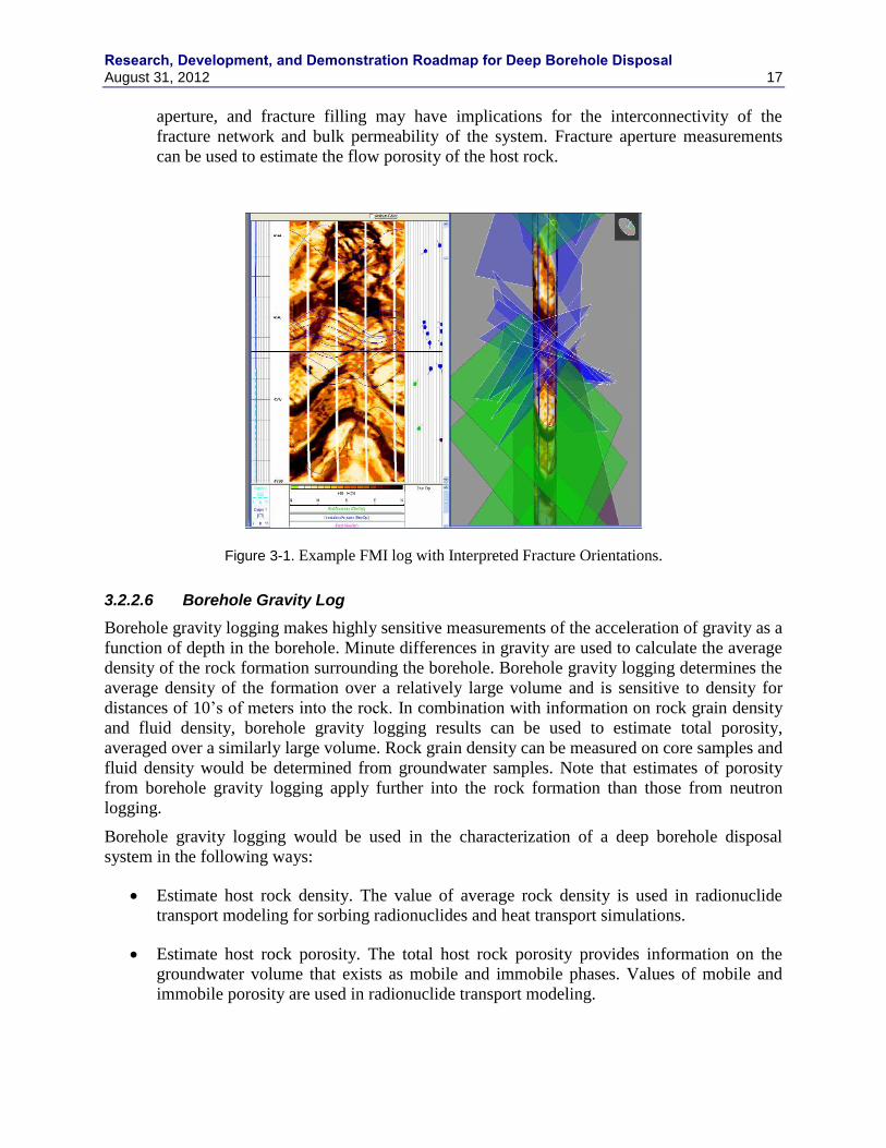
Research, Development, and Demonstration Roadmap for Deep Borehole Disposal August 31, 2012 17
aperture, and fracture filling may have implications for the interconnectivity of the
fracture network and bulk permeability of the system. Fracture aperture measurements
can be used to estimate the flow porosity of the host rock.
Figure 3-1. Example FMI log with Interpreted Fracture Orientations.
3.2.2.6 Borehole Gravity Log
Borehole gravity logging makes highly sensitive measurements of the acceleration of gravity as a
function of depth in the borehole. Minute differences in gravity are used to calculate the average
density of the rock formation surrounding the borehole. Borehole gravity logging determines the
average density of the formation over a relatively large volume and is sensitive to density for
distances of 10‟s of meters into the rock. In combination with information on rock grain density
and fluid density, borehole gravity logging results can be used to estimate total porosity,
averaged over a similarly large volume. Rock grain density can be measured on core samples and
fluid density would be determined from groundwater samples. Note that estimates of porosity
from borehole gravity logging apply further into the rock formation than those from neutron
logging.
Borehole gravity logging would be used in the characterization of a deep borehole disposal
system in the following ways:
Estimate host rock density. The value of average rock density is used in radionuclide
transport modeling for sorbing radionuclides and heat transport simulations.
Estimate host rock porosity. The total host rock porosity provides information on the
groundwater volume that exists as mobile and immobile phases. Values of mobile and
immobile porosity are used in radionuclide transport modeling.
Research, Development, and Demonstration Roadmap for Deep Borehole Disposal
18 August 31, 2012
Potential identification of fault zone and mineral alteration. Structurally complex regions
and fault zones in crystalline rock often have greater fracture intensity, lower bulk density
and higher porosity than intact rock. Mineral alteration, including the presence of hydrous
mineral phases, also may be associated with fault zones and may be detected by borehole
gravity logging.
3.2.2.7 Drill Cuttings Lithology Log
Standard logging of drill cuttings lithology provides a record of rock type and mineralogical and
textural characteristics encountered during the drilling process. This information can later be
correlated with geophysical logging to calibrate the geophysical signal with geology in the
borehole. Samples of drill cuttings would be stored for potential additional geochemical and
petrophysical analysis. Logging of drill cuttings also provides real-time information on downhole
lithology that is potentially useful to drilling operations and to the deployment of intermittent
coring and other tests at geologically important intervals of the borehole.
The usefulness of data obtained from drill cuttings is limited by uncertainty about the depth from
which the cuttings come. Drill cuttings must be transported by the drilling mud from the drill bit
to the surface resulting in a delay between the time that they are cut and when they are sampled
(this delay is a function of the depth from which they are formed). There is also mixing of
cuttings during transport to the surface. Reverse circulation drilling methods tend to isolate
drilling mud and cuttings from contamination by other rock fragments from the borehole wall,
but such fragments can still be mixed with drill cutting samples.
Drill cutting logging would be used in the characterization of a deep borehole disposal system in
the following ways:
Provide a semi-continuous vertical profile of bedrock lithology. Basic lithologic
information from the borehole is central to interpreting the geology and geologic history
of the site. Petrographic data (i.e., mineralogy and texture of rock types) would augment
geological interpretation and provide information relevant to groundwater flow and
radionuclide transport, such as porosity and sorption characteristics. Mineralogy would
also identify any occurrences of potentially economically valuable minerals.
Provide samples for laboratory testing. Estimates of parameters such as sorption
coefficients, bulk density, and bulk chemistry can be made from drill cuttings.
Provide information for drilling operations. Choices of bit type, drilling mud
composition, and weight on the bit could be influenced by rock type encountered during
drilling.
3.2.2.8 Intermittent Coring
Intermittent coring would be necessary to obtain intact samples of the host rock for detailed
analysis and testing. Continuous coring of deep boreholes for waste disposal would be
unnecessary and prohibitively expensive. Coring would be conducted at regular intervals and at
depths of particular geological interest, such as major transitions in lithology identified from drill
cuttings. For larger-diameter disposal boreholes, smaller-diameter advance coring would be
conducted, followed by overdrilling to continue the borehole. Side-wall coring is also possible
Research, Development, and Demonstration Roadmap for Deep Borehole Disposal August 31, 2012 19
for locations of particular interest that are identified by logging or testing after the drilling has
been completed for that interval.
Rock core would be used for a wide range of mineralogical, petrophysical, geochemical,
mechanical, thermal, and hydrologic testing. Intermittent coring would be used in the
characterization of a deep borehole disposal system in the following ways:
Provide mineralogy of the various lithologies encountered. Mineralogy is basic geologic
information that allows assessment of petrogenesis. Mineralogy is also relevant to
radionuclide sorption.
Provide petrophysical characteristics of the various lithologies encountered.
Petrophysical characteristics of core can be correlated to geophysical logging to improve
the accuracy of the geophysical logging.
Provide geochemical characteristics of the various lithologies encountered. Geochemical
(e.g., bulk composition of major, minor, and trace elements) and fluid inclusion studies
will provide information on the geologic history of the system, which is relevant to the
long-term stability of the site and isolation of the waste.
Provide mechanical characteristics of the various lithologies encountered. Mechanical
properties of the host rock are relevant to borehole stability and the effectiveness of seals.
Provide thermal characteristics of the various lithologies encountered. Thermal properties
of the host rock affect the temperatures of the waste canisters and related corrosion rates.
Temperatures from waste heat are also relevant to thermal-hydrologic processes.
Provide hydrological characteristics of the various lithologies encountered. Permeability
of the host rock is relevant to potential fluid migration and radionuclide transport.
3.3 Hydrogeology
Hydrogeological characteristics, including permeability, flow porosity, fluid pressures, vertical
hydraulic gradient, solute transport properties, and characteristics of the disturbed rock zone
would be determined for the host rock and overlying strata using the testing described in this
section. These hydrogeological characteristics are relevant to the long-term isolation of
radionuclides in the DBD system. In particular, deep overpressured conditions would be
detrimental to safe performance of the disposal system. Some of these methods are standard
testing techniques, but some would require adaptation to provide the information needed for
DBD. Particular care would be required in obtaining representative samples of deep fluids that
have not been contaminated by drilling activities.
3.3.1 Drill Stem Tests of Shut-In Pressure
Drill stem testing (DST) is a primary testing method in the drilling industry. It provides three
basic pieces of information on the host formation: formation pressure, formation permeability,
and water chemistry. DST equipment consists of a down-hole pressure measurement and
Research, Development, and Demonstration Roadmap for Deep Borehole Disposal
20 August 31, 2012
recording device, flow control valves that can be controlled from the surface and a sampling
device placed on the drill stem.
Ambient fluid pressure in the rock formation surrounding the borehole is measured by
determining the shut-in pressure. After the packer system is inflated to isolate the test interval
from the rest of the borehole, a control valve is opened to allow equilibration of fluid pressure
within the drill stem and the formation. Fluid pressures are monitored during the equilibration
process until a stable measurement is obtained. Fluid pressures within the formation may have
been altered during drilling and the equilibration process must allow such anomalous pressures
to dissipate.
Accurate measurements of ambient formation pressure are necessary to determine vertical
hydraulic gradients in the system and to develop an overall conceptual model of groundwater
flow in the hydrogeological system. Fluid pressure measurements in combination with factors
that affect fluid density (primarily temperature and salinity) as a function of depth are used to
calculate the overall fluid potential along the vertical extent of the borehole. Vertical gradients in
fluid potential indicate the driving force for vertical fluid movement in the system and the
occurrence of overpressured or underpressured conditions, relative to hydrostatic conditions.
Overpressured conditions would indicate the long-term potential for upward migration of
groundwater containing dissolved radionuclides from the DBD system. Hydrostatically stable or
underpressured conditions between the disposal zone and the shallow groundwater system are
thus favorable natural conditions for the safety of the DBD system.
3.3.2 Drill Stem Pump Tests
Drill stem pump tests are conducted with the drill string still in the borehole and are conducted
for shorter periods of time than packer pump tests. Pumping tests are used to determine the
hydrologic properties of formations and performance characteristics of wells. The former is of
interest here. The properties determined include hydraulic conductivity (horizontal and vertical),
specific storage or storativity, and transmissivity (hydraulic conductivity times thickness).
Drill stem pump tests typically consist of relatively rapid drawdown in pressure in a short packed
interval of the open borehole followed by a pressure recovery period. Fluid injection tests can
also be performed. The hydrologic properties are estimated from the pumping test by curve
fitting the drawdown data against solutions of various well flow equations in a process
sometimes called type curve fitting. The more straightforward type curve analyses use the Theis
solution. More complex analyses are based on solutions that relax one or more of the Theis
assumptions. Different representations of the formation and corresponding solution to the flow
are selected. The data are compared to each representation and formation parameters are
extracted from the best fit.
Results from drill stem pump tests may have significant uncertainties because of the generally
short duration of the tests, the relatively small volume of rock interrogated by the testing,
potential impacts of drilling fluids on hydraulic conductivity near the borehole, and potential
leaks from packers.
3.3.3 Packer Pump Tests
Packer pump tests are targeted at specific intervals of the borehole and are generally longer-
duration and better controlled tests of hydraulic properties than drill stem pump tests. These tests
are not conducted through the drill stem or during drilling, but are generally done after the
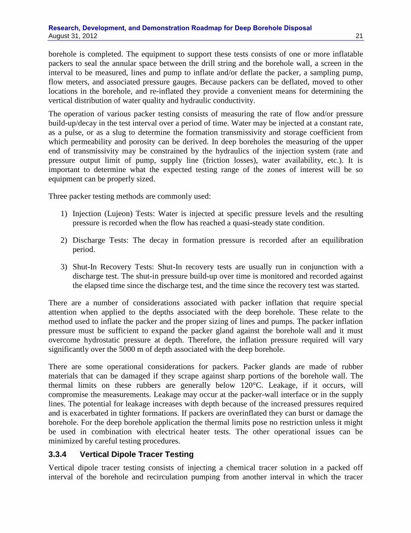
Research, Development, and Demonstration Roadmap for Deep Borehole Disposal August 31, 2012 21
borehole is completed. The equipment to support these tests consists of one or more inflatable
packers to seal the annular space between the drill string and the borehole wall, a screen in the
interval to be measured, lines and pump to inflate and/or deflate the packer, a sampling pump,
flow meters, and associated pressure gauges. Because packers can be deflated, moved to other
locations in the borehole, and re-inflated they provide a convenient means for determining the
vertical distribution of water quality and hydraulic conductivity.
The operation of various packer testing consists of measuring the rate of flow and/or pressure
build-up/decay in the test interval over a period of time. Water may be injected at a constant rate,
as a pulse, or as a slug to determine the formation transmissivity and storage coefficient from
which permeability and porosity can be derived. In deep boreholes the measuring of the upper
end of transmissivity may be constrained by the hydraulics of the injection system (rate and
pressure output limit of pump, supply line (friction losses), water availability, etc.). It is
important to determine what the expected testing range of the zones of interest will be so
equipment can be properly sized.
Three packer testing methods are commonly used:
1) Injection (Lujeon) Tests: Water is injected at specific pressure levels and the resulting
pressure is recorded when the flow has reached a quasi-steady state condition.
2) Discharge Tests: The decay in formation pressure is recorded after an equilibration
period.
3) Shut-In Recovery Tests: Shut-In recovery tests are usually run in conjunction with a
discharge test. The shut-in pressure build-up over time is monitored and recorded against
the elapsed time since the discharge test, and the time since the recovery test was started.
There are a number of considerations associated with packer inflation that require special
attention when applied to the depths associated with the deep borehole. These relate to the
method used to inflate the packer and the proper sizing of lines and pumps. The packer inflation
pressure must be sufficient to expand the packer gland against the borehole wall and it must
overcome hydrostatic pressure at depth. Therefore, the inflation pressure required will vary
significantly over the 5000 m of depth associated with the deep borehole.
There are some operational considerations for packers. Packer glands are made of rubber
materials that can be damaged if they scrape against sharp portions of the borehole wall. The
thermal limits on these rubbers are generally below 120°C. Leakage, if it occurs, will
compromise the measurements. Leakage may occur at the packer-wall interface or in the supply
lines. The potential for leakage increases with depth because of the increased pressures required
and is exacerbated in tighter formations. If packers are overinflated they can burst or damage the
borehole. For the deep borehole application the thermal limits pose no restriction unless it might
be used in combination with electrical heater tests. The other operational issues can be
minimized by careful testing procedures.
3.3.4 Vertical Dipole Tracer Testing
Vertical dipole tracer testing consists of injecting a chemical tracer solution in a packed off
interval of the borehole and recirculation pumping from another interval in which the tracer
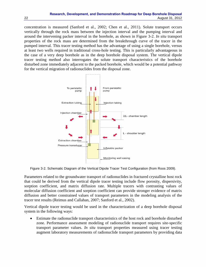
Research, Development, and Demonstration Roadmap for Deep Borehole Disposal
22 August 31, 2012
concentration is measured (Sanford et al., 2002; Chen et al., 2011). Solute transport occurs
vertically through the rock mass between the injection interval and the pumping interval and
around the intervening packer interval in the borehole, as shown in Figure 3-2. In situ transport
properties of the rock mass are determined from the breakthrough curve of the tracer in the
pumped interval. This tracer testing method has the advantage of using a single borehole, versus
at least two wells required in traditional cross-hole testing. This is particularly advantageous in
the case of a very deep borehole as in the deep borehole disposal system. The vertical dipole
tracer testing method also interrogates the solute transport characteristics of the borehole
disturbed zone immediately adjacent to the packed borehole, which would be a potential pathway
for the vertical migration of radionuclides from the disposal zone.
Figure 3-2. Schematic Diagram of the Vertical Dipole Tracer Test Configuration (from Roos 2009).
Parameters related to the groundwater transport of radionuclides in fractured crystalline host rock
that could be derived from the vertical dipole tracer testing include flow porosity, dispersivity,
sorption coefficient, and matrix diffusion rate. Multiple tracers with contrasting values of
molecular diffusion coefficient and sorption coefficient can provide stronger evidence of matrix
diffusion and better constrained values of transport parameters in the modeling analysis of the
tracer test results (Reimus and Callahan, 2007; Sanford et al., 2002).
Vertical dipole tracer testing would be used in the characterization of a deep borehole disposal
system in the following ways:
Estimate the radionuclide transport characteristics of the host rock and borehole disturbed
zone. Performance assessment modeling of radionuclide transport requires site-specific
transport parameter values. In situ transport properties measured using tracer testing
augment laboratory measurements of radionuclide transport parameters by providing data
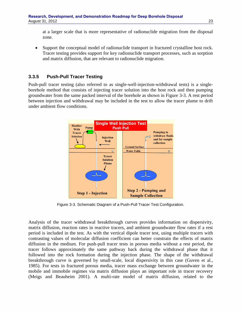
Research, Development, and Demonstration Roadmap for Deep Borehole Disposal August 31, 2012 23
at a larger scale that is more representative of radionuclide migration from the disposal
zone.
Support the conceptual model of radionuclide transport in fractured crystalline host rock.
Tracer testing provides support for key radionuclide transport processes, such as sorption
and matrix diffusion, that are relevant to radionuclide migration.
3.3.5 Push-Pull Tracer Testing
Push-pull tracer testing (also referred to as single-well-injection-withdrawal tests) is a single-
borehole method that consists of injecting tracer solution into the host rock and then pumping
groundwater from the same packed interval of the borehole as shown in Figure 3-3. A rest period
between injection and withdrawal may be included in the test to allow the tracer plume to drift
under ambient flow conditions.
Figure 3-3. Schematic Diagram of a Push-Pull Tracer Test Configuration.
Analysis of the tracer withdrawal breakthrough curves provides information on dispersivity,
matrix diffusion, reaction rates in reactive tracers, and ambient groundwater flow rates if a rest
period is included in the test. As with the vertical dipole tracer test, using multiple tracers with
contrasting values of molecular diffusion coefficient can better constrain the effects of matrix
diffusion in the medium. For push-pull tracer tests in porous media without a rest period, the
tracer follows approximately the same pathway back during the withdrawal phase that it
followed into the rock formation during the injection phase. The shape of the withdrawal
breakthrough curve is governed by small-scale, local dispersivity in this case (Guven et al.,
1985). For tests in fractured porous media, tracer mass exchange between groundwater in the
mobile and immobile regimes via matrix diffusion plays an important role in tracer recovery
(Meigs and Beauheim 2001). A multi-rate model of matrix diffusion, related to the
Research, Development, and Demonstration Roadmap for Deep Borehole Disposal
24 August 31, 2012
heterogeneous size of matrix blocks, is required to explain the tracer breakthrough curve in many
systems (e.g., Haggerty et al., 2001). Interpretation of push-pull tracer test results may be
complicated by the overlapping effects of dispersive and diffusive processes in highly
heterogeneous fractured rocks (Neretnieks 2007). Push-pull tracer testing with a rest period can
be used to estimate the ambient groundwater flux in the medium in addition to the tracer
transport parameters (Leap and Kaplan 1988).
Push-pull tracer testing would be used in the characterization of a deep borehole disposal system
in the following ways:
Estimate the radionuclide transport parameters of dispersivity and matrix diffusion in the
host rock and borehole disturbed zone. In situ transport properties from tracer testing
augment laboratory measurements of radionuclide transport parameters by providing data
at a larger scale that is more representative of radionuclide migration from the disposal
zone.
Support the conceptual model of radionuclide transport in fractured crystalline host rock.
Tracer testing provides support for key radionuclide transport processes, such as matrix
diffusion, that are relevant to radionuclide migration.
Estimate the ambient groundwater specific discharge in the host rock.
3.4 Stress/Pressure Conditions and Borehole Stability
Stress conditions and the differential in horizontal stress, in particular, are important at the depths
of DBD with regard to mechanical behavior of the host rock surrounding the borehole and to the
stability of the borehole. These conditions are potentially relevant to the disturbed rock zone,
long-term isolation of radionuclides, tectonic stability of the site, and successful construction of
the completed, cased borehole.
3.4.1 Borehole Caliper Log
Borehole caliper logging is conducted to measure the condition of a borehole, indicating
irregularities in the borehole wall, such as breakouts, cave-ins or swelling. The calipers, which
can be mechanical or sonic, measure the diameter of the borehole. A multifinger caliper
measures several diameters on the same horizontal plane simultaneously, thus measuring the
irregularity of the borehole.
Borehole caliper logging would be useful for deep borehole disposal in order to determine the
integrity of the well, where casing or cementation is needed and possibly identifying larger
fractures. The orientations and extent of borehole breakouts and tension fractures provide
information on the direction of the maximum and minimum principal horizontal stress and some
indication of the difference in the magnitudes of these stresses.
3.4.2 Dipole Shear-Wave Velocity Log
Dipole shear-wave velocity logging measures the velocity of shear waves in the borehole wall as
a function of azimuthal direction. Anisotropy in the shear-wave velocity is a function of
differential horizontal stress, rock fabric orientation (e.g., bedding or foliation), and fracture
orientations. Microfractures in the rock that are oriented in the direction of maximum horizontal
compressive stress tend to be more open than microfractures that are parallel to the minimum
Research, Development, and Demonstration Roadmap for Deep Borehole Disposal August 31, 2012 25
horizontal stress. Consequently shear wave velocity tends to be higher in the direction of
maximum horizontal stress than in the direction of minimum horizontal stress. Interpretation of
the anisotropic shear-wave velocity log can provide an estimate of the directions of maximum
and minimum in situ horizontal stress as a function of depth, even in the absence of macroscopic
indicators such as borehole breakouts and drilling-induced fractures.
Dipole shear-wave velocity logging would be used in the characterization of a deep borehole
disposal system in the following way:
Estimate the directions of in situ maximum and minimum horizontal stresses, and their
difference in magnitude. Anisotropy in horizontal stress has implications for borehole
stability and the extent of the disturbed rock zone around the borehole. In addition,
differential horizontal stress may give geological evidence regarding the tectonic history
and structural stability of the site.
3.5 Geochemical Environment
The chemical and isotopic composition of deep groundwater helps establish groundwater age and
chemical speciation. These in turn are used to constrain the degree of borehole fluid contact with
higher aquifers, the potential for canister corrosion, scaling and chemical transport.
3.5.1 Fluid Samples from Packer Testing
In situ fluid samples will be obtained through packer pump tests, drill stem pump tests, and key
first-strike water occurrences encountered while drilling. Special care will be taken to obtain
representative groundwater samples that are not contaminated by drilling fluids.
Major ion groundwater chemistry (pH, Ca+2
, Mg+2
, Na+, SO4
-2, HCO3
-, Cl
-) will be measured and
used to help constrain the history and evolution of the groundwater, the mineral and gas phases
likely to be in equilibrium with it, and its potential reactivity. Measured groundwater chemistry
will also be used as input into geochemical equilibrium models that estimate the potential for
mineral scale formation, the stability of seals and backfill materials, and the solubility and
sorption of radionuclides. Additional effort will be made to accurately measure the partial
pressure of H2 gas in order to estimate the in situ redox state of deep borehole fluids.
Salinity profiles constructed from groundwater chemistry data will be used to estimate the
resistance to upward vertical groundwater flow by salinity stratification and to assess potential
overpressured conditions. Groundwater salinity measurements will also be used to constrain the
potential for colloid-facilitated transport.
Environmental and isotopic tracers will be analyzed to build models of groundwater provenance,
groundwater residence times, flow rates through the system, and the interaction of deep
groundwater flow with the shallow hydrosphere. Fracture fluids will be sampled for stable
isotopes of water (D, 18
O), dissolved noble gas isotopic composition, 36
Cl and 129
I
concentrations. Core samples will be taken to determine pore fluid helium isotopic
concentrations and the helium neon and argon isotopic compositions of mineral and fluid
inclusions. Special sampling considerations, such as maintaining pressurization, are required to
obtain representative fluid samples for dissolved gas tracers.
Research, Development, and Demonstration Roadmap for Deep Borehole Disposal
26 August 31, 2012
3.6 Thermal Effects
Temperature and temperature gradient data are important for determining the physical conditions
at depth and the potential for future exploitation of geothermal resources at the site. In addition,
high-resolution temperature logging in combination with fracture locations is used to identify
and quantify zones of groundwater inflow and outflow in the borehole. Electrical heater testing
provides information on the thermal properties of the host rock and maximum projected
temperatures of waste canisters. These data are relevant to the intermediate- and long-term
isolation of radionuclides in the disposal system.
3.6.1 Temperature Log
Temperature logging is a commonly used geophysical measurement that records the temperature
of the fluids within the borehole as a function of depth. Temperature data are usually acquired
after drilling has been completed by running the logging tool into and out of the borehole;
however, continuous measurements during drilling are also possible. Temperature logs are also
recorded as a function of time after drilling and casing have been completed in order to correct
temperatures that have been perturbed by the drilling process. Distributed temperature sensing
systems have more recently been developed and used in wells to simultaneously measure
temperature over the length of the fiber optic cable permanently deployed in the borehole (e.g.,
Selker et al., 2006; Freifeld and Finsterle 2010).
Temperature logs in boreholes are used to characterize subsurface conditions for a number of
purposes in petroleum production, groundwater studies, geothermal exploration, and other
geoscientific studies. Temperature data are used to calculate fluid viscosity and density, apply
thermal corrections to other geophysical logs, assess geological basin hydrodynamics, model
hydrocarbon maturation, identify zones of fluid inflow, and detect zones of potential
overpressure in petroleum engineering. In groundwater studies temperature logs are used to
identify zones of inflow and outflow from the wellbore, particularly in fractured media, to
determine intra-well flow, and to delineate patterns of vertical flow in regional groundwater flow
systems. Temperature logs are used in geothermal exploration and production to delineate high-
temperature resources, calculate energy content of the system, estimate in situ thermal
conductivity of the rock, and identify productive fracture zones. Borehole temperature logging is
also used to estimate geothermal heat flux, to infer paleoclimatological conditions, and to study
tectonic and volcanic systems.
Temperature logging would be used in the characterization of a deep borehole disposal system in
the following ways:
Determine temperature conditions to calculate engineering material properties such as
fluid density, fluid viscosity, and metal strength. Other geophysical logs must be
corrected for variations in temperature with depth. Hydrostatic pressure and fluid
potential must be corrected for variations in fluid density resulting from differences in
temperature. The performance of various tools and engineering operations may be
affected or limited by high temperatures.
Determination of the geothermal gradient and the potential for geothermal resource
development. Potential future development of the host rock as a geothermal resource
would be a human intrusion event that could seriously compromise the isolation of waste
Research, Development, and Demonstration Roadmap for Deep Borehole Disposal August 31, 2012 27
disposal system. Temperature and geothermal gradient measurements would be used to
rule out the location as a site for future geothermal resource development.
Identification of zones of fluid inflow and outflow from the borehole and regions of
upward or downward flow within the wellbore. High-resolution temperature logging,
when used in conjunction with fracture imaging methods such as FMI logs (see Section
3.2.1), can be a sensitive tool for identifying transmissive fractures and fracture zones.
Zones of groundwater inflow and outflow can be used to infer the direction of the vertical
hydraulic gradient. Figure 3-4 shows an example deep borehole temperature log and the
calculated values of heat flux that are used to identify zones of vertical groundwater flow
in the fractured rock system (Mottaghy et al., 2005). The distributed thermal perturbation
sensor method has been used to make quantitative estimates of flow rates in fractures
near the borehole at high spatial resolution using transient temperature data (Friefeld et
al., 2006). Borehole locations of more transmissive fractures would be used for collecting
groundwater samples and packer hydraulic testing.
Potential inferences about regional groundwater flow. Perturbations of the geothermal
gradient from vertical groundwater flow can be used to infer the magnitude, extent, and
depth of regional groundwater flow, if the site is located in an area of significant upward
or downward flow. These inferences would be used to rule out upward fluid potential due
to regional groundwater flow patterns.
Potential inferences about paleoclimatic conditions. Long-term changes in average
surface temperature result in perturbations of the deep geothermal gradient and can be
used to determine the climatic history of the site. Future variations in climate that could
be inferred from paleoclimatic conditions would likely have no impact on performance of
the deep borehole disposal system, with the possible exception of potential continental
glaciations at some locations.
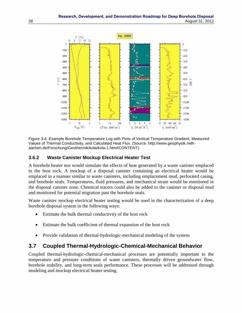
Research, Development, and Demonstration Roadmap for Deep Borehole Disposal
28 August 31, 2012
Figure 3-4. Example Borehole Temperature Log with Plots of Vertical Temperature Gradient, Measured Values of Thermal Conductivity, and Calculated Heat Flux. (Source: http://www.geophysik.rwth-aachen.de/Forschung/Geothermik/kola/kola-1.htm#CONTENT).
3.6.2 Waste Canister Mockup Electrical Heater Test
A borehole heater test would simulate the effects of heat generated by a waste canister emplaced
in the host rock. A mockup of a disposal canister containing an electrical heater would be
emplaced in a manner similar to waste canisters, including emplacement mud, perforated casing,
and borehole seals. Temperatures, fluid pressures, and mechanical strain would be monitored in
the disposal canister zone. Chemical tracers could also be added to the canister or disposal mud
and monitored for potential migration past the borehole seals.
Waste canister mockup electrical heater testing would be used in the characterization of a deep
borehole disposal system in the following ways:
Estimate the bulk thermal conductivity of the host rock
Estimate the bulk coefficient of thermal expansion of the host rock
Provide validation of thermal-hydrologic-mechanical modeling of the system
3.7 Coupled Thermal-Hydrologic-Chemical-Mechanical Behavior
Coupled thermal-hydrologic-chemical-mechanical processes are potentially important to the
temperature and pressure conditions of waste canisters, thermally driven groundwater flow,
borehole stability, and long-term seals performance. These processes will be addressed through
modeling and mockup electrical heater testing.
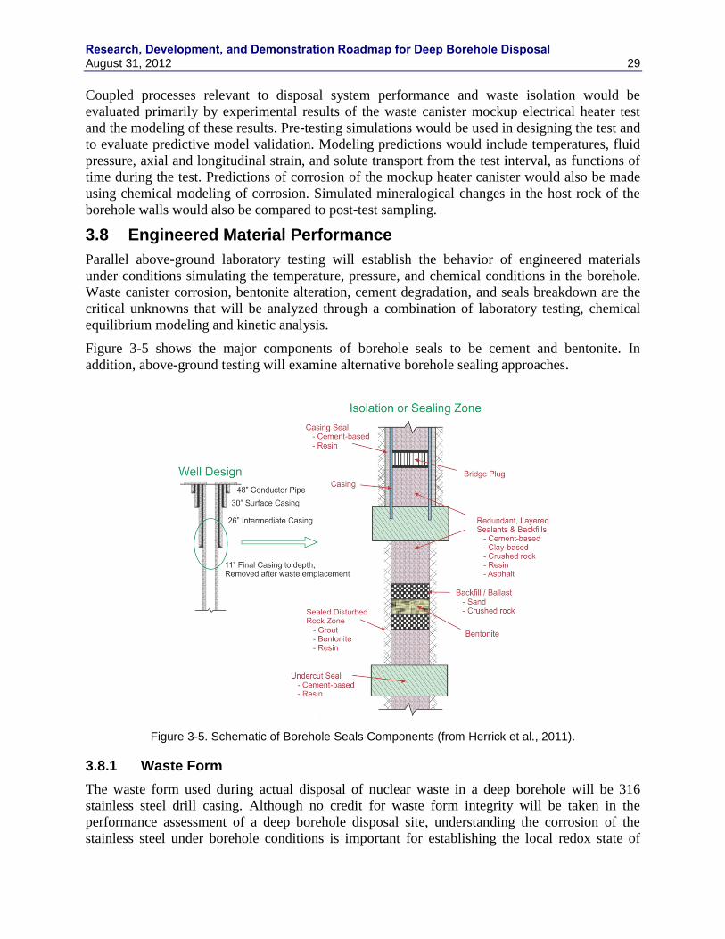
Research, Development, and Demonstration Roadmap for Deep Borehole Disposal August 31, 2012 29
Coupled processes relevant to disposal system performance and waste isolation would be
evaluated primarily by experimental results of the waste canister mockup electrical heater test
and the modeling of these results. Pre-testing simulations would be used in designing the test and
to evaluate predictive model validation. Modeling predictions would include temperatures, fluid
pressure, axial and longitudinal strain, and solute transport from the test interval, as functions of
time during the test. Predictions of corrosion of the mockup heater canister would also be made
using chemical modeling of corrosion. Simulated mineralogical changes in the host rock of the
borehole walls would also be compared to post-test sampling.
3.8 Engineered Material Performance
Parallel above-ground laboratory testing will establish the behavior of engineered materials
under conditions simulating the temperature, pressure, and chemical conditions in the borehole.
Waste canister corrosion, bentonite alteration, cement degradation, and seals breakdown are the
critical unknowns that will be analyzed through a combination of laboratory testing, chemical
equilibrium modeling and kinetic analysis.
Figure 3-5 shows the major components of borehole seals to be cement and bentonite. In
addition, above-ground testing will examine alternative borehole sealing approaches.
Figure 3-5. Schematic of Borehole Seals Components (from Herrick et al., 2011).
3.8.1 Waste Form
The waste form used during actual disposal of nuclear waste in a deep borehole will be 316
stainless steel drill casing. Although no credit for waste form integrity will be taken in the
performance assessment of a deep borehole disposal site, understanding the corrosion of the
stainless steel under borehole conditions is important for establishing the local redox state of
Research, Development, and Demonstration Roadmap for Deep Borehole Disposal
30 August 31, 2012
borehole fluids and radionuclide solubility, the potential generation of hydrogen gas, and the
identity of corrosion products that might sorb radionuclides.
Synthetic deep borehole test fluids will be developed that match the major element chemistry of
downhole fluids described in Section 3.5. To quantify corrosion rates, and possibly hydrogen
generation coupon corrosion tests will be run under ambient borehole conditions using the test
fluids under the range of temperatures expected at depth. Post-test coupon surface analyses will
be performed to identify corrosion products, for example magnetite and other spinels, and nickel
and chromium oxides. The fluid compositions and corrosion product data will be used to
verify/refine existing equilibrium and kinetic models of steel corrosion under borehole
conditions. In particular, the experimental information will be used to refine the thermodynamic
solubility products of the solids produced during corrosion. Measured corrosion product
abundances and specific volumes will be used as input into models that predict the evolution of
waste form porosity over time.
The corrosion products that form – metal oxides and spinels – will be tested for their ability to
sorb anionic radionuclides, in particular 129
I. This will involve Kd and surface complexation–
based sorption measurements done in synthetic borehole solutions at the temperatures of interest
using synthetic steel corrosion product assemblages produced by accelerated corrosion of finely
ground steel at high temperatures.
Hydrogen gas generation will be measured in the corrosion experiments and used to develop a
preliminary kinetic model of hydrogen evolution and transport in the borehole.
3.8.2 Bentonite Alteration
The potential for long-term chemical alteration to decrease the capacity of emplaced bentonite to
self-seal will be measured at the surface, but under ambient borehole conditions. Bentonite is an
effective sealing material, and will be an integral component to deep borehole disposal, because
of its low permeability and its high swelling pressure under confined conditions. Also, because
of high surface areas and high cation exchange capacity, bentonites sorb many cationic
radionuclides. Bentonites can also be chemically engineered to sorb anionic radionuclides such
as 129
I, an important dose driver. To verify the sealing properties of bentonite over the long-term,
the ability of borehole conditions to collapse the bentonite structure and to alter it to less
expansive clays will be measured.
Bentonite shrinks in contact with Ca-rich and/or high ionic strength solutions, such as should be
present at depth in a borehole. It is therefore important to establish the nature and extent of
bentonite shrinkage as a function of temperature (depth), Na/Ca ratio, and salinity. The effect of
high pH on bentonite must also be measured because borehole bentonite seals will occasionally
encounter hyperalkaline (pH > 10), high Ca leachate from cement. Bentonite structural collapse
occurs rapidly. Short-term bentonite volume changes due to fluid interaction will be measured
using synthetic deep borehole fluids identified in Section 3.5 under the temperatures likely to
prevail in the borehole. High pH cement-influenced fluids will also be tested for their effect on
bentonite expansion. Volume changes and before and after fluid compositions will be used to
develop mechanistic surface-complexation based models of bentonite expansion/contraction.
Over longer periods of time bentonite maybe thermodynamically favored to react to form mixed
layer illite-smectites, non-expandable illites and zeolites. Long-term bentonite alteration to illite
and/or mixed layer clays will be measured using accelerated testing at high temperatures.
Research, Development, and Demonstration Roadmap for Deep Borehole Disposal August 31, 2012 31
Synthetic borehole fluids, as well as high pH cement-influenced fluids, will be combined with
bentonite and over time their reaction tracked by monitoring changes in fluid chemistry and in
the solid. The measured reaction trajectories will then be used to calibrate a thermokinetic model
of bentonite transformation for use in subsequent performance assessment calculations.
Specifically, the potential change in bentonite volume will be linked to increased permeability.
The bentonite degradation experiments will be designed to build a thermokinetic model that
anticipates any change in bentonite volume, and swelling pressure, as a function of time and
fluid chemistry. A sub-goal of this model will be to predict the nature and extent of bentonite-
cement interaction over the time in the borehole. Presently it is difficult to predict the extent of
bentonite reaction, hence its effect on bentonite seal performance, because of uncertainty in the
kinetics of the individual phases. This is particularly true of cement-bentonite interaction.
3.8.3 Cement Degradation
An experimentally-based model of long-term cement stability is needed because cement will be
relied upon to bond the casing to the rock, and to anchor bridge plugs. The modes and rates of
cement degradation under borehole conditions are therefore important both for operation of the
demonstration hole, and for understanding performance of a disposal hole. Hydrated cements
contain phases that are out of chemical equilibrium with their environment and likely to
chemically alter. The solid phases that form in concrete include portlandite, amorphous calcium-
silicate-hydrate (CSH), ettringite, and silica. With time and exposure to water the assemblage
will alter to more stable and more crystalline calcite and other minerals, though the chemical
makeup of the final assemblage, the time required to reach it, and the transition assemblages that
precede it, cannot be predicted with great accuracy.
Batch and column testing of cement assemblages will be done using synthetic borehole fluids
(built from data described in Section 3.5) to establish mineralogic changes over time, their
volume change, and the evolution of fluid chemistry. Rates will also be measured at higher than
borehole temperatures to accelerate reaction and make otherwise slow reactions experimentally
accessible. Experimental variables will be cement composition, temperature, input fluid
composition, fluid/solid ratio, and time.
The principal outputs of the cement degradation testing will be
1. Clearer identification of solid cement phases and their appearance over time, and
2. Quantitative kinetic expressions (rate constants, dependencies, activation energies) for
reaction of cement phases
These two outputs will be used to construct the larger meta-model for predicting long-term
cement alteration in boreholes, and specifically the change in cement volume over time.
3.8.4 Alternative Borehole Seals
An alternative method of sealing the borehole in which a volume of crystalline rock is melted
and recrystallized in a process of “rock welding” is possible, but has not been implemented or
tested at the field scale. This borehole sealing method is similar to the waste encapsulation
approach proposed by Gibb (1999) and Gibb et al. (2008b); however, it would be applied in the
seal zone above the waste disposal zone. Heat for melting the rock surrounding the borehole
would be supplied by an electrical heater, instead of decay heat, as proposed in the waste
encapsulation approach.
Research, Development, and Demonstration Roadmap for Deep Borehole Disposal
32 August 31, 2012
The basic concept of sealing by rock welding is to fill a portion of the borehole below the seal
with crushed host rock, insert a sacrificial electrical heater, backfill with more crushed rock, run
the heater until a melt chamber is created, and then incrementally reduce the heating to control
the rate of crystallization by the melt. A granitic melt would be generated by heating the system
to about 800 ºC for a period of about 30 days. Recrystallization to a medium-grained granite
would be achieved by reducing the electrical heating such that the melt cools at a rate of less than
about 0.1 ºC/hr to a temperature of about 560 ºC (Gibb and Atrill, 2003), which would require
about 100 days. The electrical heater cables would then be cut and removed from the borehole
and overlying seals would be emplaced.
The rock welding method of sealing the borehole has several potential advantages over standard
borehole seals. The melted and recrystallized sealing material would have the same chemical and
mineralogical composition as the host rock, resulting in a seal that is in thermodynamic
equilibrium with the surrounding rock and ambient physical conditions. This equilibrium state
would ensure long-term chemical and mineralogical stability of the seal. Melting in the rock
welding methods would extend beyond the damaged rock zone created by drilling the borehole
and would seal any enhanced permeability in the volume surrounding the borehole. The
recrystallized rock melt would also seal natural fractures near the borehole.
RD&D activities for the rock welding sealing concept include further testing at the small,
intermediate, and field scales. In addition, modeling of the melting and recrystallization of the
seal system is needed, including thermal-mechanical effects, is needed prior to full-scale
implementation. Deployment of the method requires development and testing of an electrical
heater and electrical cables that are robust and durable enough to function at high temperatures
and pressures for the period of time required for rock melting and crystallization. Uncertainties
exist about the formation of cooling fractures within the rock weld seal and the permeability of
such fractures. Field-scale testing of this sealing method would include hydraulic testing of the
seal after cooling.
3.9 Long-Term Monitoring
Long term monitoring of the demonstration deep borehole is not needed as no radiologic
materials will be emplaced in it and no materials of any kind requiring monitoring will remain
after the demonstration is completed. As discussed in Section 10, one of the potential uses for the
borehole after the demonstration is as an underground research and testing facility. Activities to
be conducted in this research facility either during the demonstration or afterwards may include
testing of methods for characterization and long term monitoring. These activities can be
demonstrated to provide proof of concept applicable to future disposal of wastes in deep
boreholes at other locations of similar design and geology. As part of the prioritization of science
and engineering activities during the initial phase of the demonstration project, these activities
will be examined for their potential application to support long term monitoring and post-closure
performance confirmation relevant to future deep borehole disposal.
Long-term monitoring of DBD will be addressed using surface-based and subsurface-based
methods. Thermal, chemical, hydrologic, and mechanical evolution of the disposal system would
be amenable to a long-term monitoring and safety assurance program.
Research, Development, and Demonstration Roadmap for Deep Borehole Disposal August 31, 2012 33
3.10 Nuclear Criticality
Deployment of DBD will require assurance that nuclear criticality can be precluded at all times,
including surface operations as well as under long-term post-emplacement conditions when the
container and fuel become degraded. It has been proposed (Brady 2009, Section 4.3) that
criticality may be excluded at the stage of development of FEPS for DBD. The RD&D program
should include analysis to confirm such exclusion, along with definition of any design, operation
or site parameters that are needed to assure such exclusion.
Criticality safety is not a design, operation or permitting issue for conducting the demonstration
project, because the use of actual nuclear fuel is not anticipated. Thus, criticality safety during
RD&D is limited to conducting any analyses required to inform a transition from demonstration
to deployment, and to define any information needed from the demonstration testing.
3.10.1 Operational Criticality Safety Assurance
Because the demonstration project does not include use of fissile material, there are no criticality
safety issues associated with planning, permitting or executing the demonstration project.
Analysis will be performed during the RD&D program to provide a basis for criticality safety
assurance for DBD deployment. Because anticipated DBD waste canisters contain a single fuel
assembly, criticality safety assurance during normal handling operations and plausible abnormal
conditions can be demonstrated using standard analysis similar to those used for handling fresh
low-enriched uranium (LEU) reactor fuel.
3.10.2 Post Emplacement Criticality Safety Assurance
The primary criticality concern for DBD is to preclude any plausible scenarios for criticality in
the long-term post-emplacement period. A single fuel assembly remains subcritical even when
flooded with moderating water. Thus, any potential criticality scenario would require re-
distribution of fissile material within a container, and potentially between multiple containers in
an emplacement string. An interesting bound used in industrial practice is the minimum
criticality safe diameter for an infinite cylinder of uranium and water (at the current maximum
fuel enrichment of 5%). If the emplacement borehole is smaller than this bounding case, then
criticality assurance may be argued „a priori‟ based on simple physics. However, depending on
neutron reflection assumptions, the theoretical minimum diameter is in the range of 30 and 40
cm (LANL 1986). Given a proposed borehole diameter in the 30-50 cm range, the possibility of
criticality at the extreme of most optimal conditions may not quite be excluded. Therefore,
criticality exclusion may rely on one or more DBD design or site features that preclude criticality
in the borehole diameter selected. These features could include
Credit for the burn-up of fissile material during reactor operation
Container design, including engineered material and/or internal packing material that
limits achievable concentrations, excludes moderating water, restricts material re-
distribution or absorbs neutrons
Borehole design and emplacement details such as grout or other borehole packing that
excludes water, restricts material re-distribution or absorbs neutrons
Emplacement geology, such as composition of groundwater that absorbs neutrons or
limits concentrations of fissile material

Research, Development, and Demonstration Roadmap for Deep Borehole Disposal
34 August 31, 2012
Analysis during the RD&D program will define the parameter space of possible criticality, and
identify design and site features that can assure that DBD operates beyond any plausible
criticality scenario. Any site characteristic data needs that are identified will be added to the
demonstration and testing program.
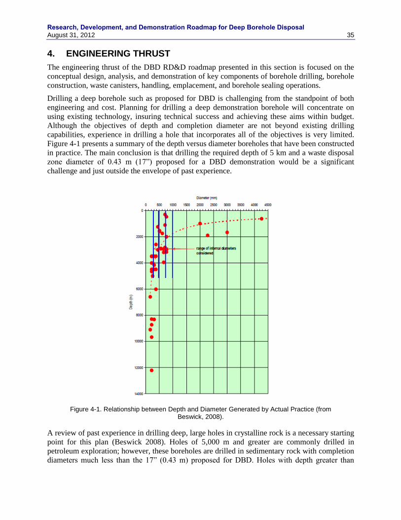
Research, Development, and Demonstration Roadmap for Deep Borehole Disposal August 31, 2012 35
4. ENGINEERING THRUST
The engineering thrust of the DBD RD&D roadmap presented in this section is focused on the
conceptual design, analysis, and demonstration of key components of borehole drilling, borehole
construction, waste canisters, handling, emplacement, and borehole sealing operations.
Drilling a deep borehole such as proposed for DBD is challenging from the standpoint of both
engineering and cost. Planning for drilling a deep demonstration borehole will concentrate on
using existing technology, insuring technical success and achieving these aims within budget.
Although the objectives of depth and completion diameter are not beyond existing drilling
capabilities, experience in drilling a hole that incorporates all of the objectives is very limited.
Figure 4-1 presents a summary of the depth versus diameter boreholes that have been constructed
in practice. The main conclusion is that drilling the required depth of 5 km and a waste disposal
zone diameter of 0.43 m (17”) proposed for a DBD demonstration would be a significant
challenge and just outside the envelope of past experience.
Figure 4-1. Relationship between Depth and Diameter Generated by Actual Practice (from Beswick, 2008).
A review of past experience in drilling deep, large holes in crystalline rock is a necessary starting
point for this plan (Beswick 2008). Holes of 5,000 m and greater are commonly drilled in
petroleum exploration; however, these boreholes are drilled in sedimentary rock with completion
diameters much less than the 17” (0.43 m) proposed for DBD. Holes with depth greater than
Research, Development, and Demonstration Roadmap for Deep Borehole Disposal
36 August 31, 2012
5,000 m in crystalline rock have generally been drilled for scientific purposes, and again, the
completion diameters are generally less than that proposed for DBD. Geothermal boreholes are
often drilled in crystalline rock at large diameter to accommodate high production volumes;
however, they are generally in the range of 2000 to 3000 m depth. Deep holes in crystalline rock
would include Kola Superdeep Borehole, Russia (12,262 m); German Continental Deep Drilling
Program (KTB) hole in Germany (9,101 m); and the Gravberg-1 borehole in Sweden (6,700 m).
The KTB hole set 13-3/8” casing in a 14-3/4” hole to a depth of 6,000 m, and is perhaps the
closest analog to the demonstration hole proposed here. Information is also available from the
Hot Dry Rock project in New Mexico and the British Hot Dry Rock project at Rosemanous. To
our knowledge, the largest diameter and most productive geothermal borehole (~50 MWe) is
Vonderahe-1 at the Salton Sea geothermal field in California. It has 24” casing set in a 32” hole
to 620 m and is completed 14-3/4” open hole to 1,684 m (A. Schreiner, personal
communication). Ikeuchi et al., (1996) document one of the world‟s hottest boreholes that was
completed in granite at a temperature of ~500o C. Recently, extensive planning was done to drill
an 8-1/2” borehole to a depth of 4,500 m in Iceland. The well (IDDP-1) was drilling at 12-1/4”
when it intersected rhyolite magma at a depth of 2104 m and temperature of 1050o C
(Holmgeirsson et al., 2010). The well was completed at that depth and is now one of the world‟s
most prolific geothermal wells (>30 MWe).
Although several of the deepest holes were drilled for scientific purposes, they also had
significant technology development aspects. Both the KTB and Kola holes utilized rigs
specifically constructed for drilling those holes. The derricks were fixed and enclosed. At the
KTB site, technological developments included computer controls and automated pipe handling
(iron roughnecks). Mobile rigs with similar technology are now available, and these
improvements greatly increase the speed and safety of drilling.
In summary, the technology exists to drill deep, large diameter holes in crystalline rock.
However, there is not a great deal of experience in drilling these holes. Technological
improvements will ultimately be required to routinely drill boreholes for deep borehole disposal
at reasonable cost if DBD is to become a practical solution to the nuclear waste management
problem.
4.1 Reference Design for Demonstration
Selection of the reference design presented in this roadmap is based on the following prioritized
list of subjective criteria (Arnold et al., 2011): (1) engineering and operational feasibility, (2)
safety and engineering assurance, (3) simplicity, and (4) cost and efficiency. Although the
reference design for a DBD system presented in Arnold et al., (2011) is conceived for full-scale
disposal activities and may differ in some specifics from the borehole for the DBD
demonstration project, it provides a reasonable basis for planning the demonstration project
borehole.
The feasibility assessment assumes currently available drilling and borehole construction
technology. The reference design also favors the use of readily available materials, such as
standard borehole casing and canister connections. Although specially built engineering systems
will be required for some components of the deep borehole disposal system (e.g., for transport
and insertion of waste canisters at the top of the borehole), the engineering challenges are similar
to those associated with emplacement of waste in mined repositories and can be overcome.
Research, Development, and Demonstration Roadmap for Deep Borehole Disposal August 31, 2012 37
4.1.1 Borehole Requirements
Technical requirements of the reference design include
Borehole is drilled and completed to a depth of about 5,000 m with the waste disposal
zone located between 3,000 and 5,000 m depth in crystalline rock.
Borehole and casing system must have sufficient stability and durability to provide a high
level of assurance that waste canisters can be emplaced at the desired depth, with
minimal probability of canisters becoming stuck during emplacement.
Borehole and casing must have sufficiently large diameter to accommodate emplacement
of test canisters.
Deviation of the borehole from its designed trajectory must be controlled such that the
distance between any two boreholes is greater than 50 m at a bottom depth of 5,000 m.
Modeling has shown the thermal interference between disposal boreholes is relatively
small for spacing of greater than 50 m. Drilling of multiple boreholes in an array must
preclude the possibility of intercepting another borehole in which waste has already been
emplaced. The spacing of waste disposal intervals at sites with multiple boreholes must
meet thermal management requirements for disposal.
Borehole and casing system must be designed such that casing can be removed from
intervals where borehole seals are to be set. Optimal performance of borehole seals
requires direct contact between seals and borehole wall.
Casing and grout in the waste disposal zone must allow thermal expansion of fluid and
flow into surrounding host rock to avoid overpressuring of fluid surrounding waste
canisters.
Drilling and borehole construction must be conducted to allow characterization of host
rock in the waste disposal zone prior to waste emplacement.
Borehole and casing system must have sufficient stability and durability to allow retrieval
of waste canisters during the operational period, if necessary. The operational period is
defined as the time until all borehole seals are emplaced and surface abandonment of the
borehole is completed.
4.1.2 Borehole Design
A schematic of the demonstration borehole reference design is shown in Figure 4-2. The
borehole is designed from the bottom up to the surface casing (whose maximum depth is limited
by the depth that can be safely drilled without a blowout preventer); that is, the expected depth
and diameter of the waste emplacement zone will determine the borehole geometry and casing
program and most of the drilling equipment requirements will follow from those criteria. Casing
is discussed further in Section 4.3.
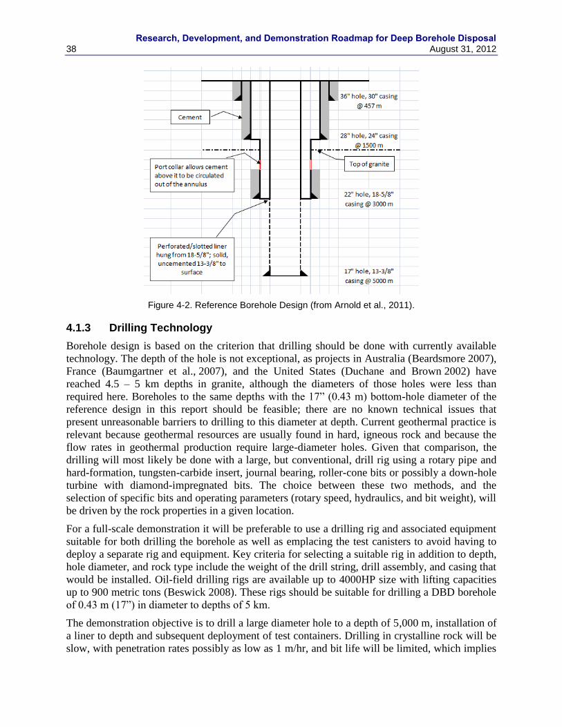
Research, Development, and Demonstration Roadmap for Deep Borehole Disposal
38 August 31, 2012
Figure 4-2. Reference Borehole Design (from Arnold et al., 2011).
4.1.3 Drilling Technology
Borehole design is based on the criterion that drilling should be done with currently available
technology. The depth of the hole is not exceptional, as projects in Australia (Beardsmore 2007),
France (Baumgartner et al., 2007), and the United States (Duchane and Brown 2002) have
reached 4.5 – 5 km depths in granite, although the diameters of those holes were less than
required here. Boreholes to the same depths with the 17” (0.43 m) bottom-hole diameter of the
reference design in this report should be feasible; there are no known technical issues that
present unreasonable barriers to drilling to this diameter at depth. Current geothermal practice is
relevant because geothermal resources are usually found in hard, igneous rock and because the
flow rates in geothermal production require large-diameter holes. Given that comparison, the
drilling will most likely be done with a large, but conventional, drill rig using a rotary pipe and
hard-formation, tungsten-carbide insert, journal bearing, roller-cone bits or possibly a down-hole
turbine with diamond-impregnated bits. The choice between these two methods, and the
selection of specific bits and operating parameters (rotary speed, hydraulics, and bit weight), will
be driven by the rock properties in a given location.
For a full-scale demonstration it will be preferable to use a drilling rig and associated equipment
suitable for both drilling the borehole as well as emplacing the test canisters to avoid having to
deploy a separate rig and equipment. Key criteria for selecting a suitable rig in addition to depth,
hole diameter, and rock type include the weight of the drill string, drill assembly, and casing that
would be installed. Oil-field drilling rigs are available up to 4000HP size with lifting capacities
up to 900 metric tons (Beswick 2008). These rigs should be suitable for drilling a DBD borehole
of 0.43 m (17”) in diameter to depths of 5 km.
The demonstration objective is to drill a large diameter hole to a depth of 5,000 m, installation of
a liner to depth and subsequent deployment of test containers. Drilling in crystalline rock will be
slow, with penetration rates possibly as low as 1 m/hr, and bit life will be limited, which implies
Research, Development, and Demonstration Roadmap for Deep Borehole Disposal August 31, 2012 39
frequent trips for bit replacement. These conditions, coupled with the large diameters and site-
specific drilling factors, mean that well costs will be not only high, but unpredictable, especially
for the first hole in a particular location.
Successfully emplacing test canisters in the emplacement zone will require a straight borehole
with as little deviation from vertical as possible. A borehole that meets deviation constraints is
required to allow canisters to be inserted into the borehole without obstruction. Directional
control during drilling is going to be critical to avoid dog legs that would decrease the probability
that a hole can be completed to the programmed depth. Keeping a hole straight will require
surveying at regular intervals, and perhaps the regular application of down-hole motors. A
straight hole is also necessary to control the distance between waste disposal zones in adjacent
boreholes in anticipated disposal borehole arrays.
4.2 Borehole Logging
The logging industry is very sophisticated due to the common application of techniques by the
petroleum industry. Borehole logging provides critical geological and geophysical information,
and an extensive program has been outlined in Arnold et al. (2011). Logging while the drilling
operation is underway, or Measurements While Drilling (MWD) technology, allows collection of
subsurface data in real time. This capability is important for the active management of the
drilling activity. In addition to MWD, open-hole logging should be scheduled to precede casing
points in the borehole. A preliminary list of proposed logging and testing for the demonstration
project that must be accommodated during drilling and borehole completion is presented in
Table 4-1.
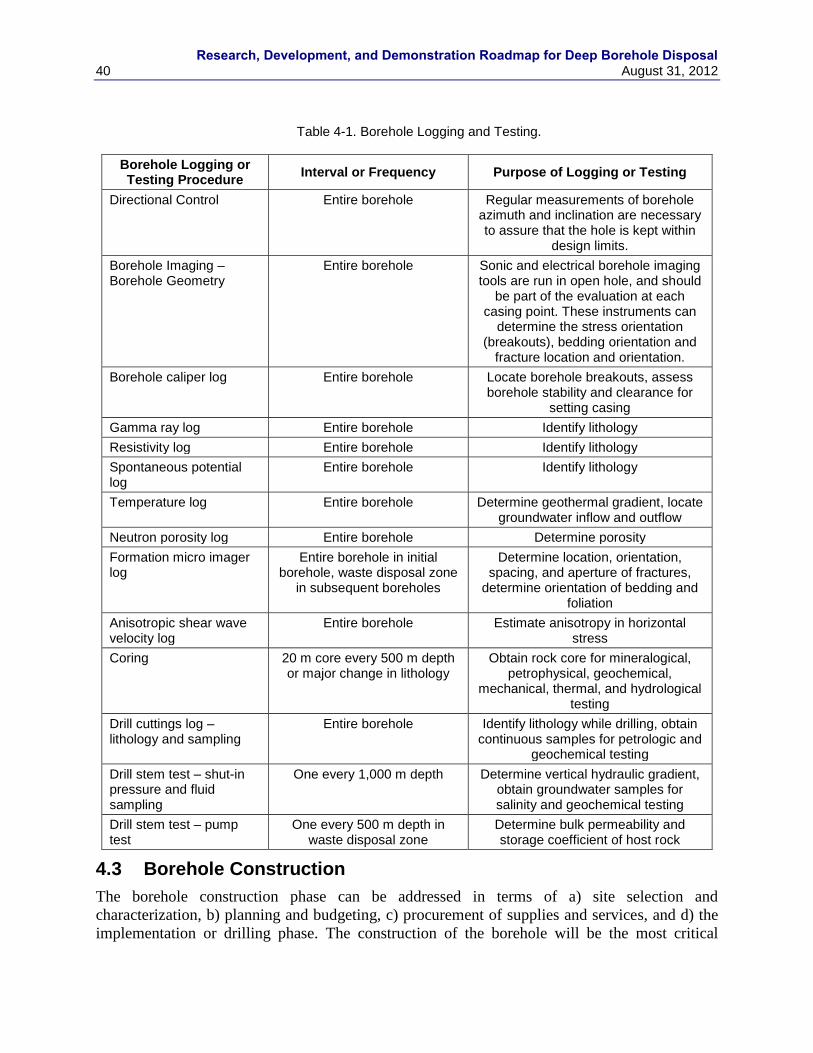
Research, Development, and Demonstration Roadmap for Deep Borehole Disposal
40 August 31, 2012
Table 4-1. Borehole Logging and Testing.
Borehole Logging or Testing Procedure
Interval or Frequency Purpose of Logging or Testing
Directional Control Entire borehole Regular measurements of borehole azimuth and inclination are necessary to assure that the hole is kept within
design limits.
Borehole Imaging – Borehole Geometry
Entire borehole Sonic and electrical borehole imaging tools are run in open hole, and should
be part of the evaluation at each casing point. These instruments can
determine the stress orientation (breakouts), bedding orientation and
fracture location and orientation.
Borehole caliper log Entire borehole Locate borehole breakouts, assess borehole stability and clearance for
setting casing
Gamma ray log Entire borehole Identify lithology
Resistivity log Entire borehole Identify lithology
Spontaneous potential log
Entire borehole Identify lithology
Temperature log Entire borehole Determine geothermal gradient, locate groundwater inflow and outflow
Neutron porosity log Entire borehole Determine porosity
Formation micro imager log
Entire borehole in initial borehole, waste disposal zone
in subsequent boreholes
Determine location, orientation, spacing, and aperture of fractures,
determine orientation of bedding and foliation
Anisotropic shear wave velocity log
Entire borehole Estimate anisotropy in horizontal stress
Coring 20 m core every 500 m depth or major change in lithology
Obtain rock core for mineralogical, petrophysical, geochemical,
mechanical, thermal, and hydrological testing
Drill cuttings log – lithology and sampling
Entire borehole Identify lithology while drilling, obtain continuous samples for petrologic and
geochemical testing
Drill stem test – shut-in pressure and fluid sampling
One every 1,000 m depth Determine vertical hydraulic gradient, obtain groundwater samples for salinity and geochemical testing
Drill stem test – pump test
One every 500 m depth in waste disposal zone
Determine bulk permeability and storage coefficient of host rock
4.3 Borehole Construction
The borehole construction phase can be addressed in terms of a) site selection and
characterization, b) planning and budgeting, c) procurement of supplies and services, and d) the
implementation or drilling phase. The construction of the borehole will be the most critical
Research, Development, and Demonstration Roadmap for Deep Borehole Disposal August 31, 2012 41
component for the demonstration project, and it is also the component that is the most expensive
and has the highest technical risk. A successful demonstration will require a high level of
technical supervision at all phases of borehole construction phase.
Site Selection and Characterization. The geology of the DBD demonstration site (site selection)
and the design and construction of the borehole go hand in hand. Without a specific site, we will
consider the generic borehole design presented in Section 4.1.2 and Arnold et al. (2011) to
represent the base line. From the borehole construction standpoint, the site selection will be
critical in assuring successful technical and budgetary completion of the DBD demonstration.
Discussion of other factors in site selection for the DBD demonstration project (e.g., topographic
relief, tectonic activity, and volcanism) is presented in Section 8. The ideal site will have the
following geological characteristics.
The overlying sedimentary section will be flat-lying and present no drilling issues such as
high-permeability zones (lost circulation), contained hydrocarbons or other difficult
drilling environments such as swelling clays, other lithologies that are hard to drill such
as chert or quartzite or overpressured fluids.
The temperature gradient in the area will be low. Since the average continental gradient is
about 30o C/km, it is anticipated that the bottom-hole temperature at 5 km will approach
150o C. Temperature influences the operational life of down-hole tools as well as mud
and cement requirements.
The area will have low differential stress. High differential stress will result in breakouts
and resultant borehole ellipticity. In addition, drilling in a high-stress environment will
result in the drill bit kicking off in the direction of the least principal horizontal stress.
The crystalline rocks that will serve as the host for the demonstration project should be as
homogeneous as possible. The foliation in crystalline rocks such as schist and gneiss will
tend to steer the bit perpendicular to the foliation. Fractures will have the same effect and
can also serve as zones of circulation loss during drilling and the migration of formation
fluids during the disposal phase.
The site will be located in an area where oil-field drilling and services companies are
close. Logistical considerations, such as the availability of services and supplies and
trucking distances will have an important influence on cost.
Once a site is selected, the more detailed planning can move forward. This section will
specifically discuss drilling issues, but planning for permitting and regulation, site acquisition or
leasing, and public relations can also move forward once the location is determined.
Planning and Budgeting. A more detailed plan and budget for the drilling operations can move
forward following site selection. At that point, the variances with respect to the scenario of
Arnold et al. (2011) will be evaluated. A Drilling Cost Estimate will be sought and prepared by
an experienced drilling engineer. This activity is influenced by the objectives of the project and
also the engineer‟s knowledge of industry equipment availability and costs. Drilling costs will
fluctuate according to demand, but a detailed drilling plan and cost estimate will provide funding
agencies with an order of magnitude cost estimate. Note that contingency costs of 30% or more
may be appropriate at this stage of the process.
Research, Development, and Demonstration Roadmap for Deep Borehole Disposal
42 August 31, 2012
Procurement of Supplies and Services. Once funding is secured, services can be procured. It is
common within the drilling industry to utilize an IADC (International Association of Drilling
Contractors) day work contract with a drilling company. However, it is also common for other
services and supplies (casing, logging, cement services and mud) to be procured separate from
the actual drilling contract. As discussed below, Quality Assurance and Quality Control are
important aspects of this phase of the project. Specifications should be rigorous and verification
is required when supplies and equipment are received at the drill site.
Drilling Phase. The drilling phase will be managed by a Company Man, the authorized
representative of the contracting entity. This person will have responsibility for the construction
of the borehole, the budget and the control of the individual service and equipment suppliers.
In the following sections, some of the more important components of the drilling phase of the
DBD demonstration are outlined.
4.3.1 Casing
The casing has a number of functions in this demonstration project. Ultimately, it provides the
enclosure for the test canisters and the pathway for their emplacement and retrieval (if
necessary). Casing protects the borehole from collapse and sloughing of the borehole wall.
Casing is also used to control pressure and guard against blow out of the borehole in case high
pressure fluids or gases are encountered during the drilling process.
Given that the borehole must accommodate waste canisters with 10.75 inches (0.27 m) outside
diameter and couplings between them with 11.75 inches (0.30 m) OD, for the reference design
presented in Arnold et al., (2011), over a depth interval from approximately 3000 to 5000 m,
then the principal criteria for casing design (in addition to those in Section 4.1.1) are borehole
control and casing strength. Borehole control considerations are generally addressed by using
standard blow-out prevention equipment (BOPE) on the surface casing and all subsequent casing
strings, while casing strength issues are controlled primarily by collapse pressure requirements.
Design considerations for each interval are discussed in more detail below. A summary of casing
properties is shown in Table 4-2. Note that the casing program will not be completely defined
until a demonstration site has been selected. A schematic view of the borehole completion is
shown in Figure 4-3.
Conductor (40”, 1.0 m casing in 48”, 1.2 m hole; not shown in schematic): The conductor is
usually line pipe set to a depth of 50 to 100 feet (15 to 30 m) and cemented in place. It provides a
flow conduit and prevents surface rubble from falling in the hole while drilling for the surface
casing. This pipe is often set by a separate contractor as part of the site preparation and is not part
of the drilling operation carried out by the principal drilling contractor.
Surface casing(30”, 0.76 m casing in 36”, 0.91 m hole): Maximum depth of the surface casing is
controlled by requirements on BOPE (that is, how deep will regulatory agencies allow drilling
without well control). This casing material is standard, minimum-property pipe weighing
approximately 235 lb/ft (350 kg/m) and with a tensile yield strength of 56,000 psi (390 MPa).
These properties give ample strength for the casing to support its own weight hanging in the
hole, and to support an external pressure of 772 psi (5.32 MPa). Using a pore pressure gradient
of 0.433 psi/ft (0.0098 MPa/m), the external pressure differential on an empty pipe would be 649
psi (4.47 MPa), so collapse is not a problem. This casing is cemented to surface and will have
BOPE installed after cementing.
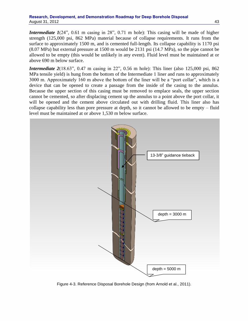
Research, Development, and Demonstration Roadmap for Deep Borehole Disposal August 31, 2012 43
Intermediate 1(24”, 0.61 m casing in 28”, 0.71 m hole): This casing will be made of higher
strength (125,000 psi, 862 MPa) material because of collapse requirements. It runs from the
surface to approximately 1500 m, and is cemented full-length. Its collapse capability is 1170 psi
(8.07 MPa) but external pressure at 1500 m would be 2131 psi (14.7 MPa), so the pipe cannot be
allowed to be empty (this would be unlikely in any event). Fluid level must be maintained at or
above 690 m below surface.
Intermediate 2(18.63”, 0.47 m casing in 22”, 0.56 m hole): This liner (also 125,000 psi, 862
MPa tensile yield) is hung from the bottom of the Intermediate 1 liner and runs to approximately
3000 m. Approximately 160 m above the bottom of the liner will be a “port collar”, which is a
device that can be opened to create a passage from the inside of the casing to the annulus.
Because the upper section of this casing must be removed to emplace seals, the upper section
cannot be cemented, so after displacing cement up the annulus to a point above the port collar, it
will be opened and the cement above circulated out with drilling fluid. This liner also has
collapse capability less than pore pressure at depth, so it cannot be allowed to be empty – fluid
level must be maintained at or above 1,530 m below surface.
Figure 4-3. Reference Disposal Borehole Design (from Arnold et al., 2011).
depth = 5000 m
depth = 3000 m
13-3/8” guidance tieback
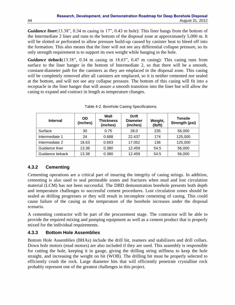
Research, Development, and Demonstration Roadmap for Deep Borehole Disposal
44 August 31, 2012
Guidance liner(13.38”, 0.34 m casing in 17”, 0.43 m hole): This liner hangs from the bottom of
the Intermediate 2 liner and runs to the bottom of the disposal zone at approximately 5,000 m. It
will be slotted or perforated to allow pressure build-up caused by canister heat to bleed off into
the formation. This also means that the liner will not see any differential collapse pressure, so its
only strength requirement is to support its own weight while hanging in the hole.
Guidance tieback(13.38”, 0.34 m casing in 18.63”, 0.47 m casing): This casing runs from
surface to the liner hanger in the bottom of Intermediate 2, so that there will be a smooth,
constant-diameter path for the canisters as they are emplaced in the disposal zone. This casing
will be completely removed after all canisters are emplaced, so it is neither cemented nor sealed
at the bottom, and will not see any collapse pressure. The bottom of this casing will fit into a
receptacle in the liner hanger that will assure a smooth transition into the liner but will allow the
casing to expand and contract in length as temperature changes.
Table 4-2. Borehole Casing Specifications.
Interval OD
(inches)
Wall Thickness (inches)
Drift Diameter (inches)
Weight, (lb/ft)
Tensile Strength (psi)
Surface 30 0.75 28.0 235 56,000
Intermediate 1 24 0.688 22.437 174 125,000
Intermediate 2 18.63 0.693 17.052 136 125,000
Guidance liner 13.38 0.380 12.459 54.5 56,000
Guidance tieback 13.38 0.380 12.459 54.5 56,000
4.3.2 Cementing
Cementing operations are a critical part of insuring the integrity of casing strings. In addition,
cementing is also used to seal permeable zones and fractures when mud and lost circulation
material (LCM) has not been successful. The DBD demonstration borehole presents both depth
and temperature challenges to successful cement procedures. Lost circulation zones should be
sealed as drilling progresses or they will result in incomplete cementing of casing. This could
cause failure of the casing as the temperature of the borehole increases under the disposal
scenario.
A cementing contractor will be part of the procurement stage. The contractor will be able to
provide the required mixing and pumping equipment as well as a cement product that is properly
mixed for the individual requirements.
4.3.3 Bottom Hole Assemblies
Bottom Hole Assemblies (BHAs) include the drill bit, reamers and stabilizers and drill collars.
Down hole motors (mud motors) are also included if they are used. This assembly is responsible
for cutting the hole, keeping it in gauge, giving the drilling string stiffness to keep the hole
straight, and increasing the weight on bit (WOB). The drilling bit must be properly selected to
efficiently crush the rock. Large diameter bits that will efficiently penetrate crystalline rock
probably represent one of the greatest challenges in this project.
Research, Development, and Demonstration Roadmap for Deep Borehole Disposal August 31, 2012 45
4.3.4 Fluid Circulation
The fluid circulation system is composed of pumps, mud and equipment for the removal of
cuttings from the circulating mud.
Mud is a general term for the fluid circulated during the drilling process. Its purposes are to cool
and lubricate the bit, remove cuttings from the borehole and condition the hole to prevent
sloughing and/or lost circulation. Mud often has a significant impact on the cost of the borehole,
particularly when the borehole is large diameter and has lost circulation.
From a practical standpoint, the drilling of the DBD demonstration borehole is going to require a
great deal of water. The most efficient way to provide this water is to access a water source with
a water well in the sedimentary section overlying the crystalline bedrock.
4.3.5 Monitoring
Monitoring technology can be designed into the demonstration. This may include a separate liner
outside the casing or a fiber optic cable cemented with the string. A fiber optic cable is used to
monitor the temperature of the borehole and could monitor heat buildup following canister
emplacement.
Another approach to monitoring that would be particularly useful in the construction of a DBD
demonstration borehole is to drill a slim hole specifically for the installation of monitoring
equipment. This option could allow permanent installation of sensors to measure temperature
and radioactivity along with pore fluid sampling capabilities.
4.4 Test Canisters
This section discusses the engineering analysis and testing associated with the design and testing
of test canisters. Actual disposal canisters would have to meet mechanical design requirements
for loading, welding, transportation, surface handling, and borehole emplacement under normal
operating conditions. The test canister will be designed to be representative of an actual disposal
canister and will meet key requirements of the disposal canister. In addition, testing will be
conducted to demonstrate test canister performance under representative accident conditions,
such as dropped canisters and canisters stuck in the borehole.
4.4.1 Test Canister Design Requirements
This section describes the requirements for the demonstration test canister design. The test
canister will be designed to some of the key requirements as the actual disposal canister. These
requirements will include requirements for key phases of surface operations, canister
emplacement in the DBD system, and down-hole integrity until seals are emplaced.
Test canisters will be designed to test key design requirements of the actual waste disposal
canister, with emphasis on characteristics of the waste canisters that are important to postclosure
safety and preclosure down-hole operational safety. Engineering analysis and testing of the waste
canisters relevant to other preclosure safety and operational assurance issues will not be
addressed through detailed testing in the borehole demonstration project, but are described in
general terms in this section.
Technical requirements of the waste canister design include
Research, Development, and Demonstration Roadmap for Deep Borehole Disposal
46 August 31, 2012
Waste canister design must provide a high level of assurance that no leakage of
radioactive materials will occur during handling and emplacement of the waste canisters.
Welding and sealing of canisters must prevent release of radionuclides in solid, liquid, or
gaseous state.
Waste canisters must maintain structural integrity during loading, transportation, and
handling prior to emplacement.
Waste canisters must maintain structural integrity during emplacement, sealing, and
abandonment of the borehole disposal system. Waste canister design must provide a high
level of assurance that the canisters can withstand fluid pressures, mechanical loads, and
temperatures during emplacement and the remainder of the operational phase.
Waste canisters must have an integrated system for connection to other waste canisters
and to drill pipe for lowering to the disposal zone as a string of canisters. Connections
must have sufficient strength to withstand mechanical loads during and after
emplacement, and for potential retrieval during the operational phase.
Internal length of the waste canister must be sufficient to accommodate most intact PWR
fuel rods. Waste canister should have a minimum internal length of 4.2 m.
Waste canisters should retain their integrity as long as practical. However, the deep
borehole disposal concept does not rely on the waste canisters as a significant barrier to
radionuclide release beyond the operational period.
Design, handling, and emplacement of waste canisters must preclude any possibility of
nuclear criticality.
The test canister design requirements include the following characteristics that will be assessed
in the engineering thrust of the demonstration project:
Test canisters will maintain structural integrity during loading, transportation, and
handling prior to emplacement testing.
Test canisters must maintain structural integrity during down-hole testing. Test canister
design will assure that the canisters can withstand fluid pressures, mechanical loads, and
temperatures without leakage into or out of the test canister during emplacement and
retrieval from the test borehole.
Test canisters must have an integrated system for connection to other test canisters and to
drill pipe for lowering to the disposal zone as a string of canisters. Connections must have
sufficient strength to withstand mechanical loads during and after emplacement, and for
retrieval from the test borehole.
Internal length of the test canister must be sufficient to accommodate most intact PWR
fuel rods. Test canister should have a minimum internal length of 4.2 m.
Hydrostatic fluid pressure on test canisters will be a function of depth and the fluid density
within the borehole. Fluid density will be a function of salinity and temperature, which will also
vary with depth. High salinity brines are expected to occur in the host rock at the depths of deep
borehole demonstration project, but fluid composition within the cased borehole could be
controlled to a certain extent during test canister emplacement. The fluid pressure design
Research, Development, and Demonstration Roadmap for Deep Borehole Disposal August 31, 2012 47
requirement is conservatively based on an assumed salinity profile varying from fresh water at
the surface to a density of 1.1 x fresh water density at a depth of 500 m and varying from 1.1 x
fresh water density at 500 m depth to 1.3 x fresh water density at a depth of 5000 m. The
assumed temperature gradient is 25 ºC/km. The resulting fluid pressure at the bottom of the
borehole is about 57 MPa (8250 psi) and this pressure is used as the test canister design
requirement.
The nominal mechanical load requirement for test canisters is based on the assumption that the
loaded waste canisters will be emplaced in strings of 40 canisters (approximately 200 m
intervals). The maximum compressive force on the bottom canister in the string after
emplacement will be equal to the maximum tensile force on the uppermost canister in the string
while being lowered into the borehole. The mechanical load design requirement is based on a
preliminary canister design in which each canister was assumed be loaded with 421 PWR fuel
rods with a weight of 2.39 kg/fuel pin (calculated from data for reference nuclear fuel assemblies
in U.S. DOE 1997). The approximate total weight of the canisters and waste for 40 canisters is
69,400 kg (153,000 lbs). The reference canister design in Arnold et al. (2011) contains fewer fuel
rods than used to estimate the weight given above, so the actual weight of the canister string
would be less than this. Buoyancy in the fluid within the borehole is conservatively disregarded
in this design requirement. Forces associated with the potential retrieval of waste canisters during
the operational phase must be considered in the safety margin relative to this design requirement.
4.4.2 Test Canister Conceptual Design
The conceptual test canister design will be presented in this section and is based on the reference
design presented in Arnold et al. (2011). The test canister design will be relatively simple and
use materials and components available in the petroleum and geothermal industries. Drawings of
the design and specifications including canister dimensions, welds, and materials will be
specified as part of the demonstration project.
The reference test canister is designed to withstand hydrostatic pressure in the borehole without
internal mechanical support. Canister wall thickness to withstand a maximum hydrostatic
pressure of 8250 psi (57 MPa) is calculated based on American Petroleum Institute (API) 5CT
specifications for K55 seamless pipe and a safety factor of 1.2. Standard manufacturing
tolerances for the wall thickness of API 5CT steel tubing is ± 12.5 % and collapse strengths are
calculated in the minimum thickness within this tolerance. A higher level of confidence in waste
canister integrity could be achieved if tubing manufactured to tighter tolerances than the API
standard were used to construct the canisters. Waste canisters with a higher tolerance for wall
thickness would also help insure that the maximum number of fuel rods could be packed into
each canister.
The reduction in yield strength with increasing temperature has been estimated from various
sources. American Society of Mechanical Engineers (ASME) recommended design factors from
boiler and pressure vessel code for carbon and low alloy steels at 300 ºC indicate a factor of 0.78.
Various manufacturers provide estimates of this design factor. Tenaris reported an average
number to use of 0.86 for their 55,000 psi (380 MPa) yield strength casing. Grant Pridco reported
0.74 and Hunting 0.82 for their 80,000 psi (550 MPa) yield strength casing. Canister wall
thickness design is based on a retained yield strength factor of 0.82 at 300 oC and 0.90 at 160
oC.
Manufacturers can be required to run yield strength tests at elevated temperatures as an
acceptance criterion for the material used in the canisters. The resulting test canister dimensions
Research, Development, and Demonstration Roadmap for Deep Borehole Disposal
48 August 31, 2012
have an outside diameter of 10.75 inches, inside diameter of 8.33 inches, and wall thickness of
1.21 inches.
Connections between test canisters consist of “premium” threaded coupled connections with an
outside diameter of 11.75 inches (0.30 m) and 5 threads per inch. A custom design for these
connections with a wall thickness of 1.21 inches (3.07 cm) would be required to match the tubing
used in the test canister design. Data on existing connections with smaller wall thickness made
from L80 grade steel have a coupled minimum yield strength of 80,000 psi (550 MPa).
The top of the assembled test canisters would have a J-slot safety joint screwed into the
uppermost test canister. The safety joint is an assembly that is easy to release once the canister
string is on the bottom of the test emplacement zone; allows for reengagement when retrieval is
necessary. There are a number of slightly different designs, depending on the manufacturer, but
all operate in a similar manner.
The test canisters will be sealed by welding plugs below and above the test canister contents.
Test canister contents will consist of ballast material to match the weight of fuel rods in the
waste canisters. Test canisters will also contain experimental packets that could measure
deformation of the canister walls, temperature history, pressure history, and evidence of test
canister leakage.
The test canisters will easily withstand the mechanical compressive and tensile mechanical loads
from overlying canisters and from the weight of the canister string during test emplacement.
With a nominal wall thickness of 1.21 inches (3.07 cm) the test canister walls have a cross-
sectional area of 36.265 square inches (234 square cm). The resulting stress from an overlying
(or underlying) weight of a 200-m string of canisters of 153,000 pounds (69,400 kg) is about
4,220 psi (29.1 MPa). This mechanical stress is much less than the thermally degraded yield
strength of 55,000 psi (380 MPa) steel, resulting in a safety factor of greater than 10 for these
mechanical loads.
4.4.3 Demonstration Canister Testing
This section describes the types of tests that will be conducted to evaluate key aspects of test
canister performance. Demonstration canister tests will be conducted to verify canister integrity
under mechanical stresses from hydrostatic pressures, temperatures, and mechanical loading
downhole. In addition, operations associated with connecting canisters to the drill string and
disconnection at waste disposal depths, along with retrieval of test canisters will be verified.
Test canisters will be assembled as a string at the borehole collar, lowered to disposal depths,
disengaged from the drill string, left in place for some period of time, reengaged to the drill
string, and removed from the borehole. Assembling the test canister string, lowering to disposal
depths, and disengaging from the drill string will demonstrate the operational ability to emplace
waste canisters and the design requirement of connecting canisters. Test canisters will be left in
place in a configuration representative of a disposal borehole (i.e., canisters surrounded by
bentonite mud) to expose them to ambient temperature, pressure, and hydrochemical conditions.
Recording sensors in test canisters will record the temperature and deformation history for the
validation of engineering analyses of canister strength and deformation. Reengaging and
removing test canisters will demonstrate the ability of operational retrieval. Test canisters will be
analyzed for corrosion rate, weld integrity, and potential leakage after they are removed from the
borehole to verify canister integrity requirements.
Research, Development, and Demonstration Roadmap for Deep Borehole Disposal August 31, 2012 49
4.4.4 Additional Canister Testing for a Disposal Program
Additional canister testing beyond the scope of the demonstration project will eventually be
required if the DBD program were to be implemented for disposal of SNF and HLW. Such
testing would be conducted on the finalized waste canister design and as part of routine quality
assurance procedures during disposal operations. Such testing is described in general, conceptual
terms in this section.
Waste canister testing prior to loading with waste would verify the dimensions of the canister
and yield strength of materials used in their construction. Canister wall thickness would be
measured to verify a manufacturing tolerance of ± 6 %. Integrity of threads for connections
would be inspected and verified. Yield strengths of steel canister walls and connections would be
tested at elevated temperatures to verify that design requirements had been met.
The canisters will be sealed by welding plugs below and above the waste. The bottom plug could
be welded in place before the fuel rods are loaded into the canister and the connection threads are
cut into the canister. The top plug would have to be robotically welded in place after the waste
has been loaded into the canister. If welding of the top plug is conducted before the connection
threads are cut in the top of the canister, then the upper threads would have to be cut robotically
in a shielded environment. If the upper threads are cut before loading waste and welding of the
upper plug, then the weld would have to be far enough from the threads to prevent distortion of
the threads. RD&D activities would be required to develop the engineering technology for
robotic welding.
Drop testing of a mock-up of the loaded waste canister would be conducted to demonstrate the
ability of the waste canister design to withstand possible accidents during handling and
emplacement. The loaded waste canister design should not leak after a potential fall from raising
the shipping cask to a vertical position prior to rail transference to the borehole. Nor should a
loaded waste canister leak if it strikes the bottom of the borehole at terminal velocity after the
accidental release of a canister string in the borehole fluid.
4.5 Canister Loading Operations
Several operational aspects of waste canister loading require elaboration through analysis and
design. These operations include fuel rod consolidation, loading of fuel rods into canisters, and
canister sealing. Although these operations will not be physically demonstrated, the conceptual
operational and engineering aspects of these operations will be examined and developed as part
of the DBD demonstration project. These operations are discussed in this section of the report.
4.5.1 Used Fuel Loading Operations
The disposal system in the reference design in Arnold et al. (2011) is based on the disassembly
of used PWR nuclear fuel assemblies at the reactor sites (or at a centralized facility) and loading
of individual fuel rods in the waste canisters. Although this procedure entails greater cost and
effort in the loading of the waste canisters, it allows for a smaller diameter waste canister, a
smaller diameter borehole, and greater operational assurance for the construction of the borehole
to the required depth. The higher density of used fuel in the waste canisters also results in fewer
total waste canisters, fewer boreholes, and lower transportation, drilling and operational costs.
Fuel consolidation technology and costs have been analyzed in previous studies that are
summarized in Gibbs (2010). Results of these studies indicate that dismantling assemblies and
consolidating of fuel rods is technically feasible, costs are reasonable, and that the costs of
Research, Development, and Demonstration Roadmap for Deep Borehole Disposal
50 August 31, 2012
consolidation would be offset by savings in number of canisters and drilling costs for deep
borehole disposal. Individual fuel rods can be removed from most PWR fuel assemblies and
many reactor sites have existing facilities that could be adapted for the disassembly of fuel
assemblies in fuel storage pools. Additional reactor site facilities would likely be required for the
sealing, shielding, welding and handling of the loaded waste canisters. However, the engineering
for such potentially portable facilities should be relatively straightforward, given the modest size
of the waste canisters.
Waste canisters are also designed for the disposal of vitrified DOE defense high-level waste or of
vitrified waste from the reprocessing of commercial spent nuclear fuel. Vitrified high-level waste
could be poured as molten glass into a thin-walled steel container, which could then be placed
into the waste canister.
Although demonstration of fuel assembly consolidation is not planned for this project nor is it
thought to be necessary because of prior evaluations of this process, demonstration of waste
canister loading could be accomplished using unirradiated fuel assemblies that could be safely
handled in an unshielded facility. Engineering design of the fuel rod consolidation and canister
loading facility would involve design of the remote handling or robotic components of the
system. Such design could be based on similar existing facilities, such as the pilot waste
conditioning plant in Gorleben, Germany.
4.5.2 Canister Welding Demonstration
Actual waste canisters would be sealed by welding plugs below and above the waste. The bottom
plug could be welded in place before the fuel rods are loaded into the canister and the connection
threads are cut into the canister. The top plug would have to be robotically welded in place after
the waste has been loaded into the canister.
Although demonstration of canister welding is not planned for this project, demonstration of
waste canister welding operations could be accomplished in a straightforward manner for the
bottom plug in the canister, which can be done before waste loading. Engineering design of the
robotic welding procedure for the upper plug in a shielded facility could be based in part on
similar facilities for sealing vitrified HLW canisters. Welding of sealing plugs in the canister
would be inspected using x-ray imaging following waste loading. During operations surface
samples of the loaded waste canisters would be tested for any radiological contamination.
4.6 Waste Handling
Several operational aspects of waste handling will require elaboration through analysis and
design. While radioactive waste will not be part of the demonstration project, operational
procedures for shielded transference of loaded waste canisters to shipping casks, from shipping
casks, positioning over the borehole collar, and insertion in the borehole are required for a
licensed “production” facility. Although the waste handling operations will not be physically
demonstrated, the conceptual operational and engineering aspects of waste handling will be
examined and developed as part of the DBD demonstration project. Waste handling processes
are discussed in this section.
4.6.1 Canister Transference to Shipping Cask
The safety of a loaded waste canister during transport would need to be evaluated. Loaded waste
canisters would be transported to the deep borehole drill site by tractor trailer using
Research, Development, and Demonstration Roadmap for Deep Borehole Disposal August 31, 2012 51
transportation casks similar to existing designs for the shipping of SNF. Such casks provide
shielding to workers and the public during transport, and protect the fuel from release in the
event of an accident. The safety of these cask models would need to be reevaluated for the
somewhat greater weight and radioactive inventory of the loaded waste canisters, relative to that
of a single PWR fuel assembly for which these shipping casks were designed. A single DBD
reference canister could be shipped at one time in these casks. These cask models may have to be
remodeled or redesigned to allow rotation to a vertical orientation, positioning over the borehole,
and attachment of the waste canister to the drill string for emplacement in the borehole.
4.6.2 Canister Transference to Borehole
Surface handling of the loaded waste canisters at an actual disposal site would be conducted in a
manner similar to that described in Woodward and Clyde Consultants (1983). The Woodward
and Clyde system calls for rotation of the shipping cask to a vertical position from the tractor
trailer adjacent to the emplacement rig onto a rail transporter. The cask containing the loaded
waste canister would then be moved along a short rail system into an enclosed area beneath the
elevated drill floor of the rig. Remotely operated equipment would open the upper cover of the
shipping cask, the drill pipe would be attached to the top of the canister, the canister would be
lifted, the lower cover of the shipping cask would be opened, the canister would be lowered into
shielded basement below the rail transporter, and the canister would be attached to the
underlying waste canister that has been locked into place at the borehole collar in the basement.
The underlying waste canister would then be unlocked at the borehole collar, the waste canister
string would be lowered by one canister length, and the new canister would be locked at the
borehole collar. The drill pipe would then be unscrewed from the top of the canister, raised
above the drill floor, the empty shipping cask would be moved away from the rig, and the
process would be repeated for the next waste canister. All operations at unshielded locations
would be performed remotely and monitored by video links.
The Woodward and Clyde Consultants (1983) waste handling system calls for use of a standard
drill rig to drill and construct the borehole, and a separate specially designed emplacement rig for
emplacing the waste canisters and performing borehole plugging and sealing operations. This
strategy has the advantage of freeing up the drill rig for drilling and construction of the next
borehole at the same site, while waste is simultaneously being emplaced by the emplacement rig.
It has the disadvantage of requiring the capital investment in a specialized, dedicated
emplacement rig that probably lacks the full capability and capacities of a deep drill rig. A deep
drill rig probably would be better equipped to deal with unplanned events, such as a lodged
waste canister string. Alternatively, it may be more effective to modify an existing deep drill rig
to drill the borehole and to emplace the waste and perform borehole sealing and plugging
operations.
4.7 Waste Emplacement
Some aspects of waste emplacement operations, including assembly of the test canister string,
lowering the string in the borehole, and disengaging the test canister string, will be addressed in
the test canister demonstration discussed in Section 4.4. Several additional operational aspects of
actual waste canister emplacement in the borehole disposal system will require elaboration
through further analysis and design during the DBD demonstration project. These additional
operational aspects are discussed in this section and include assembly of an actual waste canister
Research, Development, and Demonstration Roadmap for Deep Borehole Disposal
52 August 31, 2012
string using remote handling methods, insertion of the borehole string in the emplacement grout,
and setting bridge plugs and cement plugs to support overlying waste canisters.
4.7.1 Waste Canister String Demonstration
This section describes the operations that would be demonstrated for attaching strings of test
canisters together and lowering into the borehole. Test canisters would be emplaced in the
disposal zone of the borehole in strings of 40 canisters, with a total length of about 200 m,
depending on the test canister design.
Test canisters would be emplaced in the emplacement zone of the borehole in strings of 40
canisters, with a total length of about 192 m, based on the test canister design presented in
Arnold et al. (2011). Each test canister string would be lowered to the emplacement zone and
would rest on the bottom of the borehole in the case of first string or on the bridge plug and
cement emplaced above the previous test canister string for subsequent canister strings. The test
canister string would then be disengaged from the drill pipe using the J-slot assembly. A bridge
plug and cement would be set above the test canister string prior to the emplacement of the next
test canister string.
One issue of concern that would not be addressed in the test canister string demonstration
described above for non-heat generating test canisters is the maximum temperature rating for
commercially available bridge plugs and the temperature increases that may arise from the
radioactive waste in an actual disposal implementation. Several standard designs for bridge plugs
that would fit the 13-3/8 inch (0.34 m) casing in the disposal zone are rated up to 400 ºF
(204 ºC). This maximum temperature rating is sufficient for close proximity to the representative
spent nuclear fuel analyzed in Brady et al. (2009) and the low-temperature canister design.
However, this maximum temperature rating for bridge plugs could be exceeded within one year
near actual waste canisters that contain the higher heat output vitrified HLW. This problem will
be addressed by evaluating the feasibility of implementing a waste loading strategy that places
the higher heat output waste canisters in the middle of canister strings. This strategy would
increase the distance between the hotter waste canisters and the bridge plugs, protecting them
from exceeding their maximum temperature rating.
4.7.2 Emplacement Grout Demonstration
A synthetic oil base mud containing bentonite will be used in the canister emplacement zone
during test canister emplacement. Although the test canisters will not be cemented in place, the
high concentration of bentonite in the mud will provide some degree of grouting around the
canisters over time. The emplacement mud will also provide lubrication to assure emplacement
at the desired depth and facilitate operational retrieval of the canisters. This section describes the
operations and processes that will demonstrate the emplacement of grout in the canister
emplacement zone.
4.7.3 Setting Bridge Plugs
The primary function of the bridge plug is to provide a base upon which the thicker cement plug
can be emplaced. Together the bridge plug and cement plug must support the weight of the
overlying test canister string. This section describes the operations and processes for
demonstrating the emplacement of a bridge plug and cement plug in a deep borehole.
Research, Development, and Demonstration Roadmap for Deep Borehole Disposal August 31, 2012 53
Each test canister string will be separated by a bridge plug and overlying cement plug. The
cement plug would also invade the annulus between the perforated casing liner and the borehole
wall, and provide a barrier to fluid migration within this annulus between test canister string
intervals. Due to incompatibility between the oil base mud and cement, any oil base mud in the
borehole above the bridge plug will be flushed out prior to setting the cement plug.
Bonding recommendations are made on the basis of the compressive strength of the set cement
and on the assumption that the material satisfying the strength requirements will also provide an
adequate bond. In a borehole, the shear bond is typically used to determine the weight of pipe the
cement can support. The shear bond force divided by the cement/casing contact area yields the
shear bond stress. Smith (1989) presents a relationship for the support capacity of the cement
sheath outside a casing to support the weight of the casing:
where F is the force or load to break cement bond (pounds), Sc is the compressive strength of the
cement (psi), dp is the casing diameter (inches), and hcis the height of cement column (feet). The
typical strength of a Class H cement at 15,000 ft (4570 m) depth is conservatively taken as 4000
psi for the anticipated temperatures and pressures (Smith 1989, Table 4.8). Using an inside
diameter of the casing of 12.459 inches (0.316 m) and the weight of the overlying canister string
of 153,000 lbs (69,400 kg), the length of the cement plug required is about 3.2 ft (0.98 m). The
bond properties of the cement to the casing are highly dependent on the cement job, age of
casing, surface finish of casing, amount of time the cement has had to cure, and the type of fluid
in the borehole amongst other possible factors. Taking these unknown factors into consideration
and the desire to infiltrate and form a barrier in the annulus between the casing and the borehole
wall, a cement plug of 10 m is recommended.
Numerous bridge plug types are commercially available for use in the test canister emplacement
procedure. Both mechanical and inflatable designs are available. Some inflatable, packer-style
bridge plugs can be filled with cement for permanent installation. Two example bridge plugs are:
1) Weatherford PBP bridge plug and 2) TechTool high-pressure bridge plug. Both of these
designs are rated for temperatures up to 400 ºF (204 ºC) and for a casing size of 13⅜ inches
(0.34 m).
4.7.4 Operational Radiological Monitoring
While radioactive materials will not be part of the DBD demonstration project, they are for a
“production” disposal facility and monitoring ability requires demonstration for later phases of
the program. Operational safety for waste emplacement would be assured through routine
monitoring and planning for potential unexpected conditions or events.
Radiological monitoring would include dosimeters for all workers and visitors on site and during
transportation of waste canisters. Equipment would be routinely sampled and monitored for
radioactive contamination using standard radiation safety procedures. Real time monitoring of
radiation levels in working areas of the drill rig would be conducted and connected to an alarm
system during waste emplacement operations.
Fluids circulated in the borehole would need to be continuously monitored for radiation levels
and periodically sampled for analysis of radionuclide concentrations. Design of monitoring
Research, Development, and Demonstration Roadmap for Deep Borehole Disposal
54 August 31, 2012
equipment and operational procedures for radiological protection during drilling operations may
be readily adapted from drilling experience at the Nevada Test Site, in which drilling was done
into contaminated underground nuclear testing sites. Detection of excessive radiation in the
borehole fluid would cause immediate suspension of waste emplacement. In addition, storage
capacity for contaminated fluids would be part of the rig design and actions would be taken to
securely store any contaminated fluids produced at the surface.
4.8 Seal Design and Closure
Although the demonstration borehole will not be permanently sealed, considerable effort will go
into designing, downhole emplacement, and downhole testing of seals. The integrity of each
constructed seal will be tested, and then will be drilled through to keep the borehole open.
Candidate seal designs will be developed for downhole testing. It is particularly important to test
seal emplacement feasibility and seal integrity at depths greater than 2 km. Seal materials will
include cement and bentonite and potential alternative sealing using the rock welding approach
(see Section 3.8.4). Above-ground testing of long-term cement and bentonite degradation is
described in Sections 3.8.2 and 3.8.3. Emplacement approaches are described below.
4.8.1 Seal Emplacement Operations
While the plugging of boreholes with clay and cement seal materials is routine in the
construction, geotechnical, and water well industries, plugging must be demonstrated
successfully at the much greater depths of deep boreholes. Candidate methods for emplacing
bentonite and cement are described below.
4.8.1.1 Bentonite Emplacement
A widely accepted method of sealing shallow holes is to use a grout pump to carefully pump
bentonite slurries downhole. Alternatively, bentonite chips or pellets can be dropped, usually via
a tremie pipe, into holes containing standing water, providing a relatively low permeability seal.
Methods that will be demonstrated for placing clay plugs at depth include container, pellet, and
perforated tube methods.
1. The Container Method. In the container method, a highly compacted plug segment is
confined in a sealed container until it reaches its destination in the borehole. Either a
ram in the container or the drill string can be used to push the plug out through a lid at
the end of the container. The plug segment will rest on the previously placed clay
core or concrete plug and be hydrated from every side swelling from the outside in
based on the clays water uptake rate at the emplaced condition. The advantages to the
method are that no clay is lost to erosion during the placement phase and high clay
densities can be obtained on placement of the plug.
2. The Pellet Method. The pellet method utilizes either commercially available clay
pellets or sorted bits from crushed highly compacted blocks. The suggested method to
place pellet plugs is very similar to that of the container method: fill a sealed transfer
bucket with dry pellets, lower the bucket to the desired position, and push the pellets
out with a ram or the drill rod. The advantage of this method is that it utilizes
commercially available clay pellets and the pellets hydrate more quickly. The
disadvantage is that the clay density is much lower than either of the two alternatives.
Research, Development, and Demonstration Roadmap for Deep Borehole Disposal August 31, 2012 55
3. The Perforated Tube Method. This technique was originally developed during the
international Stripa project in Sweden. The plugs consist of perforated tubes
containing tightly fitting blocks of highly compacted clay. The plug is lowered in the
hole and left there. Clay swells on contact with water through the perforations of the
tube, contacts the walls of the borehole and encases the tube. Copper is recommended
for the tubing material due to its chemical stability and that its impact on smectite
clay is negligible. The advantage is that high saturated densities for the clay are
attainable. The disadvantage is that if the plug is not placed at the seal location
quickly enough during the placement operations, the clay will begin to hydrate and
swell. This could cause resistance to insertion of the plug, possibly even resulting in a
stuck plug. It is inevitable that erosion of the clay will occur and that will lower the
initial density of the clay.
4.8.1.2 Cement Emplacement
The following cement plug emplacement approaches will be tested:
1. Balanced Plug Method.The balanced plug method involves pumping a desired
quantity of cement slurry through a drillpipe or other tubing until the cement level
outside the drillpipe/tubing is equal to that inside. The pipe or tubing is then pulled
out slowly from the slurry leaving the plug in place. The method is simple and
requires no special equipment other than a cementing service unit. The characteristics
of the mud are very important in the balancing of a cement plug in a well, particularly
the ability to circulate freely during placement.
2. Cement Squeeze Method. The cement squeeze method is often used to isolate
wellbore intervals or to cement fractures to obtain static equilibrium. The cement
squeeze method involves pumping slurry to the desired interval through a drillpipe or
other tubing. Sufficient hydraulic pressure is applied to the slurry so that the slurry
begins to dehydrate and is no longer flowable and a filter cake forms at the plug
edges. The cement becomes a barrier that prevents fluid movement. A cement
squeeze job is either a bradenhead squeeze or packer squeeze. A bradenhead squeeze
is a relatively low-pressure cement squeeze job in which the cement is pumped down
a tubing string or drillstring (workstring). The drillstring is positioned just above the
zone to be squeezed. The drillstring casing head (“bradenhead”) annulus is closed.
Pressure is applied through the workstring to squeeze cement into position. A packer
squeeze is a relatively high-pressure cement squeeze job. A packer is used to seal the
workstring annulus above the zone to be squeezed. The cement is pumped down the
drillstring, and pressure is applied.
3. Dump Bailer Method. Typically, the dump bailer method is used for placing cement
on platforms formed by previous plugging operations or on mechanical isolation
tools. The method is usually used at shallow depths; but with the formulation of
retarded setting cementing compositions, it has been used to depths exceeding 3.5 km
(12,000 ft). The dump bailer containing a measured quantity of cement is lowered
into the well on a wireline. The bailer is opened on impact with the previously placed
structure or by electric activation and is raised to release the cement slurry at this
location. The method has certain advantages in that the tool is run on wireline and the
depth of the cement plug is easily controlled. The cost of a dump bailer job is usually
Research, Development, and Demonstration Roadmap for Deep Borehole Disposal
56 August 31, 2012
low compared with one using conventional pumping equipment. Two disadvantages
of the method are that mud can contaminate the cement unless the hole is circulated
before dumping and there is a limit to the quantity of slurry that can be placed per
run, and an initial set may be required before the next run can be made.
4. The Two-Plug Method. In the two-plug method, top and bottom tubing plugs are run
to isolate the cement slurry from the well fluids and displacement fluids on top of the
previous plug or a bridge plug set at depth. A special baffle tool is run on the bottom
of the string and placed at the depth desired for the bottom of the cement plug. This
tool permits the bottom tubing plug to pass through and out of the tubing. Cement is
then pumped out of the string and begins to fill the annulus. The top tubing plug,
following the cement, is caught in the plug-catcher tool and causes a sharp rise in the
surface pressure, which indicates that the plug has landed. The latching device holds
the top tubing plug to help prevent cement from backing up into the string, but
permits reverse circulation. This design allows the string to be pulled up after cement
placement to “cut off” the cement plug at the desired depth by establishing reverse
circulation through the plug catcher; thus excess cement is allowed to be reversed up
and out of the tubing. The string is then pulled, leaving a cement plug that should last
indefinitely and provide good, hard support for any subsequent operation. Advantages
of the two-plug method are that (1) it minimizes the likelihood of overdisplacing the
cement; (2) it forms a tight, hard cement structure; and (3) it permits establishing the
top of the plug. The two-plug method of plugging is preferred to the balanced
method.
5. Mechanical Plugs. Mechanical isolation tools such as bridge plugs, cement retainers,
and permanent packers are used to isolate sections of the wellbore. These maybe set
at prescribed depths by wireline, tubing, workstring, or drill pipe. Cement caps are
then placed on top of the plug to provide a secondary seal.
4.8.2 Seal Integrity Testing
As-built measurements of the seal system performance will be done, including
Material testing of as-emplaced materials (can include standard strength/permeability
tests of cast cement samples, remolded clays, etc.) (e.g., API, 1990)
In situ strength tests – commonly accomplished by applying vertical loads via the drill rig
itself, or via application of a packer pressure system if the overall formation permeability
is low.
In situ permeability testing – using a packer system, apply pressure above a seal system
component and monitor pressure decay to determine system permeability.
4.9 Operational Retrievability
Retrievability during the waste canister emplacement processes is a consideration in the safe
operation of a DBD facility and certain elements of operational retrieval require demonstration
during the DBD demonstration project. Care is exercised in the design of the borehole to
minimize the likelihood of a stuck waste canister during emplacement. These borehole design
considerations and requirements are identified and discussed. In an operating facility if an
unexpected situation arises where a waste canister becomes stuck during emplacement, retrieval
Research, Development, and Demonstration Roadmap for Deep Borehole Disposal August 31, 2012 57
will need to be conducted or a decision made to abandon the borehole and move to another
borehole in the field. The demonstration of the retrieval operation is developed and described in
this section.
One unplanned scenario of concern would be that a canister string becomes lodged in the
borehole at some depth shallower than the disposal zone. A number of measures in the reference
design and operations make this scenario highly unlikely. The borehole will be fully cased from
the surface to the bottom during waste emplacement operations. The casing will be surveyed
using a caliper tool prior to waste emplacement to detect deviations in inside diameter, bending,
shearing, or any other obstructions that could cause the waste string to become lodged. A guide
shoe with rounded nose will be on the first canister in the string. The formation testing prior to
waste emplacement will provide information concerning the potential for rock breakout during
operations potentially compromising the casing. Additional assurance could be achieved by
using a disposable caliper tool that would be attached below the lowermost waste canister in the
string. This tool would send real-time measurements of the casing inside dimensions to operators
via telemetry. Lowering of the drill string would be stopped if a potential obstruction is
encountered ahead of the waste canister string, preventing it from becoming stuck.
If a waste canister string becomes lodged in the borehole, considerable force could be applied by
the drill rig to pull, push, or rotate the canister string, based on the strength of the waste canisters
and the connections between them. If the waste canister string cannot be dislodged, then a bridge
plug and cement plug could be set above the canister string. Waste emplacement could continue
if the lodged waste canister string is located in the waste disposal zone. If the waste canister
string is lodged in the liner casing above the waste disposal zone, then it would be possible to
extract the liner from the borehole, pulling the lodged canister string up with the liner. This
method of retrieval would require a drill rig capable of lifting the combined weight of the liner
and the lodged canister string. Furthermore, the liner casing would have to be of sufficient
strength to support the weight of itself and the lodged canister string during the extraction
process. The borehole would be grouted, sealed, and abandoned if the waste canister string is
lodged above the disposal zone and cannot be retrieved. Other retrieval methods, such as mining
from the surface, may be possible for a waste canister string that is lodged at a very shallow
depth.
Retrieval of test canisters during the DBD demonstration project would be conducted as
described in Section 4.4.3. This part of the canister testing would serve as a demonstration of
retrieval for canisters that are not stuck in the borehole. A demonstration of retrieval of stuck
waste canisters is beyond the scope of the DBD demonstration project and would have to be
addressed in later phases of the disposal program through further analysis or, potentially, by
downhole testing.
Research, Development, and Demonstration Roadmap for Deep Borehole Disposal
58 August 31, 2012
5. IDENTIFICATION & PRIORITIZATION OF RESEARCH AND DEVELOPMENT NEEDS
This section describes the systematic approach that will be used to identify and prioritize RD&D
science and engineering needs during the demonstration phase of the DBD concept. An example
implementation of the approach is presented. The complete prioritization will occur in an early
phase of the demonstration. This approach is similar to the systems engineering approach
developed previously for the Used Fuel Disposition (UFD) Campaign R&D Roadmap (U.S.
DOE 2011). For this roadmap the initial identification and prioritization of RD&D needs will
rely on existing qualitative and quantitative information and consider both pre- and postclosure.
5.1 Systematic Approach
At a high level the systematic approach described herein involves ranking of candidate science
and engineering activities against multiple metrics and combining these multiple rankings into an
overall priority score using objective functions and a set of weighting factors on the individual
metric components.
The approach will utilize qualitative and quantitative analyses and leverage existing information
from multiple sources. The approach will utilize an adaption of the classical “performance
assessment methodology” (Bonano et al., 2010) to supplement the qualitative analyses supporting
the evaluation of the science and engineering activities. The steps in the approach include
Identify potential RD&D needs (information needs and knowledge gaps) (Section
5.2)
Characterize the RD&D needs to support prioritization (Section 5.3)
Prioritize RD&D needs based on an established methodology (Section 5.3)
Each of these steps is described below.
5.2 Identification of Potential RD&D Needs
The identification step involves the following three activities:
1. Identify objectives of the deep borehole disposal demonstration (Section 5.2.1)
2. Identify the relevant features, events, and process associated with deep borehole disposal
(Section 3.1)
3. Identify potential science and engineering activities needed for the demonstration
(Section 5.2.2)
5.2.1 Objectives of the DBD Demonstration
The project objectives are presented in Section 2.2. The two high-level objectives focused on
science and engineering activities are refined to establish the objectives of the identification and
prioritization activity as follows:
1. Identify and prioritize science and engineering activities that directly support site
selection for the demonstration.
Research, Development, and Demonstration Roadmap for Deep Borehole Disposal August 31, 2012 59
2. Identify and prioritize science and engineering activities that directly support the drilling
and completion of a deep borehole.
3. Identify and prioritize science and engineering activities that require evaluation and
verification during the demonstration.
4. Identify science and engineering gaps associated with the demonstration.
5.2.2 Identification and Characterization of Science and Engineering Activities
As presented in Section 3.1, the FEPs identified as relevant to DBD are used to inform and
identify areas where science thrust and characterization activities can contribute to a successful
demonstration. The engineering thrust activities of potential relevance for evaluation and
prioritization are identified using previously developed information generated in Brady et al
2009 and Arnold et al 2011 and references therein. This information is supplemented with expert
judgment, as well as the UFD R&D Road Map (U.S. DOE 2011). Table B-1 of Appendix B
summarizes the potential science and engineering activities that support the deep borehole
demonstration. Detailed discussions of these activities were presented in Sections 3 and 4. They
are organized here according to those activities supporting demonstration site selection, borehole
drilling and completion, and postclosure.
Summaries of the different types of activities are provided below.
5.2.2.1 Direct Support of Demonstration Site Selection
These activities are primarily science activities that provide technical information to assist in the
selection of a site for the deep borehole demonstration. From a technical perspective the focus is
on obtaining a site where there is a high confidence of successfully demonstrating the deep
borehole concept and its supporting technical basis. There are non-technical factors that also
must be considered when siting the deep borehole demonstration and these factors are discussed
in Section 8.
5.2.2.2 Direct Support of Drilling for the Demonstration
These activities are primarily engineering activities that are potentially required to “get a hole in
the ground.” The borehole reference design presented in Section 4.1.2 has been designed so that
borehole construction has a high probability of success given today‟s technology, as well as
having size and depth to meet reasonable waste form and disposal needs. While the deep
borehole demonstration is not intended to be a “drilling research” program, a borehole of this
size and depth has never been constructed and does challenge the technology envelope as
discussed in Section 4. The activities supporting drilling for the demonstration fall into the areas
of drilling technology, borehole logging, borehole construction (casing, liner, cementing),
operational, and borehole monitoring. These activities are described in Section 4, with some of
the supporting drilling science activities described in Section 3.
5.2.2.3 Postclosure Activities Requiring Evaluation and Verification in the Demonstration
These are science and engineering activities that may require verification of proof of concept
during the demonstration in order to identify and address technical gaps associated with potential
future disposal. Postclosure activities comprise a significant portion of the activities that need to
be demonstrated. Subsets of these activities also support demonstration site selection and
Research, Development, and Demonstration Roadmap for Deep Borehole Disposal
60 August 31, 2012
drilling. Details of post closure science and engineering activities were presented in Sections 3
and 4, respectively, and fall into the following areas:
Geology (Section 3.2)
Hydrogeology (Section 3.3)
Stress/Pressure Conditions and Borehole Stability (Section 3.4)
Geochemical Environment (Section 3.5)
Thermal Effects (Section 3.6)
Engineered Material Performance (Sections 3.8 and 4.8)
Waste Form Performance (Section 3.8)
Long-Term Monitoring (Section 3.9)
Nuclear Criticality (Section 3.10)
System and Sub-system Modeling (Section 6)
Canister Emplacement and Operational Retrieval (Sections 4.7 and 4.9)
Fuel Assembly Consolidation (Section 4.5)
5.3 Evaluation and Prioritization of RD&D Activities
The next step is to evaluate and prioritize each of the potential science and engineering activities
with respect to a set of metrics. Example metrics are identified in Section 5.3.1. Evaluation and
prioritization will occur during the initial phase of the demonstration. (See schedule in Section
9.5.) The process used, and an example of its use, are presented in this roadmap. Prioritization of
activities is organized around those supporting demonstration site selection, borehole drilling and
completion, preclosure, and postclosure.
An example of the evaluation and prioritization process of the potential science and engineering
activities identified in Section 5.3.2 is conducted in the section for a subset of the science
activities. This is intended only to demonstrate the prioritization process and the results of this
example can be expected to change when the more comprehensive evaluation is conducted in the
initial phase of the demonstration. Example results are presented in a summary table of ranking
for each metric and the cumulative. The evaluation and prioritization is conducted in three steps:
Identify metrics and characteristics of the science and engineering activities to
support prioritization.(Section 5.3.1).
Evaluate the science and engineering activities for demonstration in the context of the
established metrics. (Section 5.3.2).
Determine objective functions and tally combined ranking (Section 5.3.3).
5.3.1 Identification of Metrics
The identification of metrics for evaluating and prioritizing potential science and engineering
activities relevant to deep borehole demonstration is the first step. Because of the desire to
simplify metric scoring and the qualitative nature of available information, the use of expert
judgment is required and the assessment is somewhat subjective. There are three basic types of
metrics:
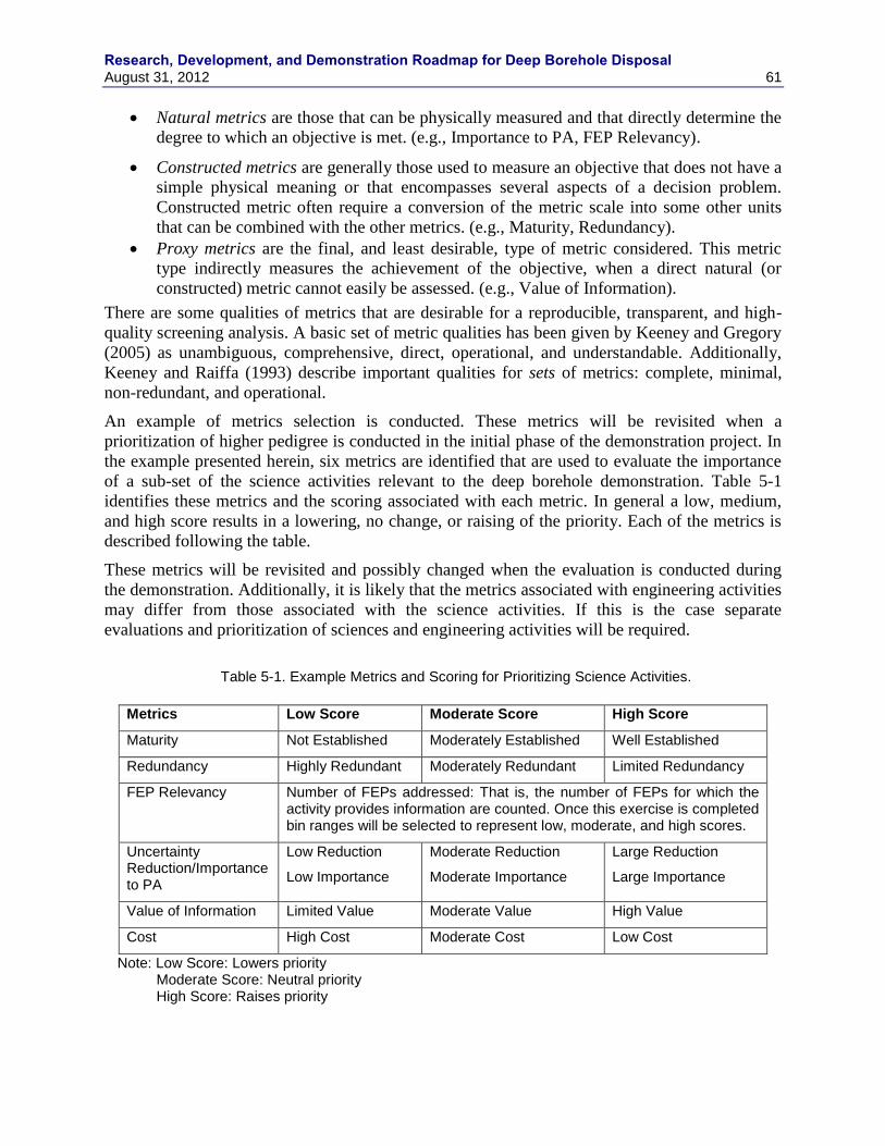
Research, Development, and Demonstration Roadmap for Deep Borehole Disposal August 31, 2012 61
Natural metrics are those that can be physically measured and that directly determine the
degree to which an objective is met. (e.g., Importance to PA, FEP Relevancy).
Constructed metrics are generally those used to measure an objective that does not have a
simple physical meaning or that encompasses several aspects of a decision problem.
Constructed metric often require a conversion of the metric scale into some other units
that can be combined with the other metrics. (e.g., Maturity, Redundancy).
Proxy metrics are the final, and least desirable, type of metric considered. This metric
type indirectly measures the achievement of the objective, when a direct natural (or
constructed) metric cannot easily be assessed. (e.g., Value of Information).
There are some qualities of metrics that are desirable for a reproducible, transparent, and high-
quality screening analysis. A basic set of metric qualities has been given by Keeney and Gregory
(2005) as unambiguous, comprehensive, direct, operational, and understandable. Additionally,
Keeney and Raiffa (1993) describe important qualities for sets of metrics: complete, minimal,
non-redundant, and operational.
An example of metrics selection is conducted. These metrics will be revisited when a
prioritization of higher pedigree is conducted in the initial phase of the demonstration project. In
the example presented herein, six metrics are identified that are used to evaluate the importance
of a sub-set of the science activities relevant to the deep borehole demonstration. Table 5-1
identifies these metrics and the scoring associated with each metric. In general a low, medium,
and high score results in a lowering, no change, or raising of the priority. Each of the metrics is
described following the table.
These metrics will be revisited and possibly changed when the evaluation is conducted during
the demonstration. Additionally, it is likely that the metrics associated with engineering activities
may differ from those associated with the science activities. If this is the case separate
evaluations and prioritization of sciences and engineering activities will be required.
Table 5-1. Example Metrics and Scoring for Prioritizing Science Activities.
Metrics Low Score Moderate Score High Score
Maturity Not Established Moderately Established Well Established
Redundancy Highly Redundant Moderately Redundant Limited Redundancy
FEP Relevancy Number of FEPs addressed: That is, the number of FEPs for which the activity provides information are counted. Once this exercise is completed bin ranges will be selected to represent low, moderate, and high scores.
Uncertainty Reduction/Importance to PA
Low Reduction
Low Importance
Moderate Reduction
Moderate Importance
Large Reduction
Large Importance
Value of Information Limited Value Moderate Value High Value
Cost High Cost Moderate Cost Low Cost
Note: Low Score: Lowers priority Moderate Score: Neutral priority High Score: Raises priority
Research, Development, and Demonstration Roadmap for Deep Borehole Disposal
62 August 31, 2012
Maturity: A considerable amount of work has been completed both in the U.S. and other
countries on many, if not all, of the RD&D activities under consideration. This body of work can
be used to determine the current level of understanding, or maturity with respect to deep
borehole demonstration and to identify information gaps.
The following guidelines are used to help evaluate the maturity scoring of the activities as either
“not established,” “moderately established,” or “well established”:
Not Established: Includes
o Fundamental Gaps in Method: The representation of the activity (conceptual
and/or mathematical, experimental) is lacking
o Fundamental Data Needs: the activity requires data or parameters that is lacking
Moderately Established: Includes
o Improved Representation: The activity may be technically defensible, but for
application to the deep borehole addition proof of concept would be beneficial
o Improved Confidence: The activity (both method and any supporting data) exist
or are readily obtainable and is technically defensible but there is not widely-
agreed upon confidence concerning the activity‟s use in a deep borehole
environment
o Improved Defensibility: Related to confidence, but focuses on improving the
activities technical basis, and defensibility, with respect to the deep borehole
environment
Well Established: Includes
o Well Understood – The representation of the activity is well developed, has a
strong technical basis, and is defensible.
Redundancy: Some of the RD&D activities are redundant in that they provide the same or very
similar information. Many activities also address the same FEPs. The following is used to help
evaluate the redundancy scoring of the activities as either “highly redundant,” “limited
redundancy,” or “no redundancy.” The scoring for each activity is determined by the number of
FEPs that overlap with other activities. Because some activities address more FEPs than others
(FEPs relevancy), the score is normalized to the number of FEPs the activity addresses. The
result is then binned into three ranges: limited redundancy (< 2), moderately redundant (>2 but
<4), highly redundant (>=4).
FEP Relevancy: Most of the RD&D activities directly support FEPs evaluation by providing
information needed to either defensively exclude a FEP from further consideration in a safety
assessment or in providing information needed to include a FEP in the safety assessment. The
scoring is determined by identifying the number of FEPs an activity supports. Scoring is binned
into three ranges: Low (1 to 4, inclusive), Medium (5 to 8, inclusive), and High (>8).
Uncertainty Reduction/Importance to PA: As used here uncertainty reduction is related to
importance of the RD&D activity to the safety assessment. System and sub-system sensitivity
analyses evaluate the sensitivity of parameters described with uncertain values or distributions of
values to performance or safety metrics. Existing system and sub-system analyses of deep
borehole disposal will be used to evaluate uncertainty reduction scoring of the activities as either
“low reduction/importance,” “moderate reduction/importance,” or “large reduction/importance.”
This metric is the only metric that utilizes quantitative information and results from modeling
studies.
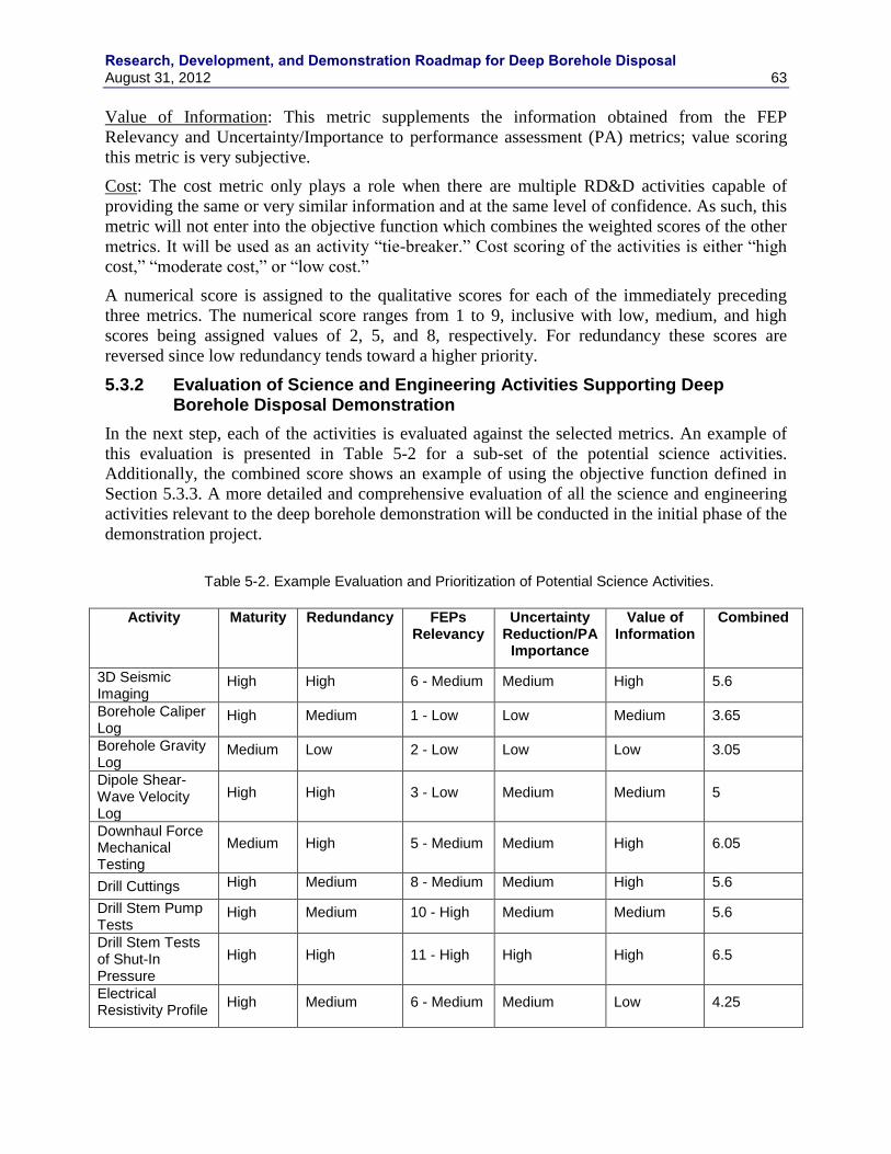
Research, Development, and Demonstration Roadmap for Deep Borehole Disposal August 31, 2012 63
Value of Information: This metric supplements the information obtained from the FEP
Relevancy and Uncertainty/Importance to performance assessment (PA) metrics; value scoring
this metric is very subjective.
Cost: The cost metric only plays a role when there are multiple RD&D activities capable of
providing the same or very similar information and at the same level of confidence. As such, this
metric will not enter into the objective function which combines the weighted scores of the other
metrics. It will be used as an activity “tie-breaker.” Cost scoring of the activities is either “high
cost,” “moderate cost,” or “low cost.”
A numerical score is assigned to the qualitative scores for each of the immediately preceding
three metrics. The numerical score ranges from 1 to 9, inclusive with low, medium, and high
scores being assigned values of 2, 5, and 8, respectively. For redundancy these scores are
reversed since low redundancy tends toward a higher priority.
5.3.2 Evaluation of Science and Engineering Activities Supporting Deep Borehole Disposal Demonstration
In the next step, each of the activities is evaluated against the selected metrics. An example of
this evaluation is presented in Table 5-2 for a sub-set of the potential science activities.
Additionally, the combined score shows an example of using the objective function defined in
Section 5.3.3. A more detailed and comprehensive evaluation of all the science and engineering
activities relevant to the deep borehole demonstration will be conducted in the initial phase of the
demonstration project.
Table 5-2. Example Evaluation and Prioritization of Potential Science Activities.
Activity Maturity Redundancy FEPs
Relevancy Uncertainty
Reduction/PA Importance
Value of Information
Combined
3D Seismic Imaging
High High 6 - Medium Medium High 5.6
Borehole Caliper Log
High Medium 1 - Low Low Medium 3.65
Borehole Gravity Log
Medium Low 2 - Low Low Low 3.05
Dipole Shear- Wave Velocity Log
High High 3 - Low Medium Medium 5
Downhaul Force Mechanical Testing
Medium High 5 - Medium Medium High 6.05
Drill Cuttings High Medium 8 - Medium Medium High 5.6
Drill Stem Pump Tests
High Medium 10 - High Medium Medium 5.6
Drill Stem Tests of Shut-In Pressure
High High 11 - High High High 6.5
Electrical Resistivity Profile
High Medium 6 - Medium Medium Low 4.25
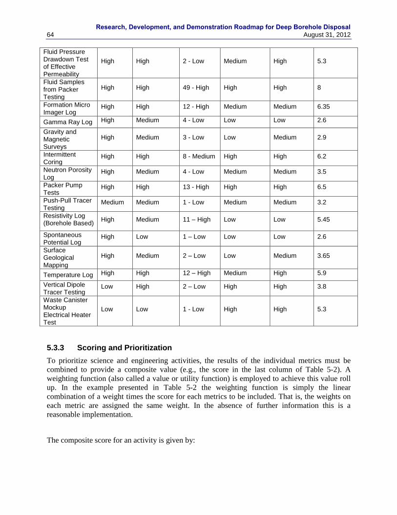
Research, Development, and Demonstration Roadmap for Deep Borehole Disposal
64 August 31, 2012
Fluid Pressure Drawdown Test of Effective Permeability
High High 2 - Low Medium High 5.3
Fluid Samples from Packer Testing
High High 49 - High High High 8
Formation Micro Imager Log
High High 12 - High Medium Medium 6.35
Gamma Ray Log High Medium 4 - Low Low Low 2.6
Gravity and Magnetic Surveys
High Medium 3 - Low Low Medium 2.9
Intermittent Coring
High High 8 - Medium High High 6.2
Neutron Porosity Log
High Medium 4 - Low Medium Medium 3.5
Packer Pump Tests
High High 13 - High High High 6.5
Push-Pull Tracer Testing
Medium Medium 1 - Low Medium Medium 3.2
Resistivity Log (Borehole Based)
High Medium 11 – High Low Low 5.45
Spontaneous Potential Log
High Low 1 – Low Low Low 2.6
Surface Geological Mapping
High Medium 2 – Low Low Medium 3.65
Temperature Log High High 12 – High Medium High 5.9
Vertical Dipole Tracer Testing
Low High 2 – Low High High 3.8
Waste Canister Mockup Electrical Heater Test
Low Low 1 - Low High High 5.3
5.3.3 Scoring and Prioritization
To prioritize science and engineering activities, the results of the individual metrics must be
combined to provide a composite value (e.g., the score in the last column of Table 5-2). A
weighting function (also called a value or utility function) is employed to achieve this value roll
up. In the example presented in Table 5-2 the weighting function is simply the linear
combination of a weight times the score for each metrics to be included. That is, the weights on
each metric are assigned the same weight. In the absence of further information this is a
reasonable implementation.
The composite score for an activity is given by:
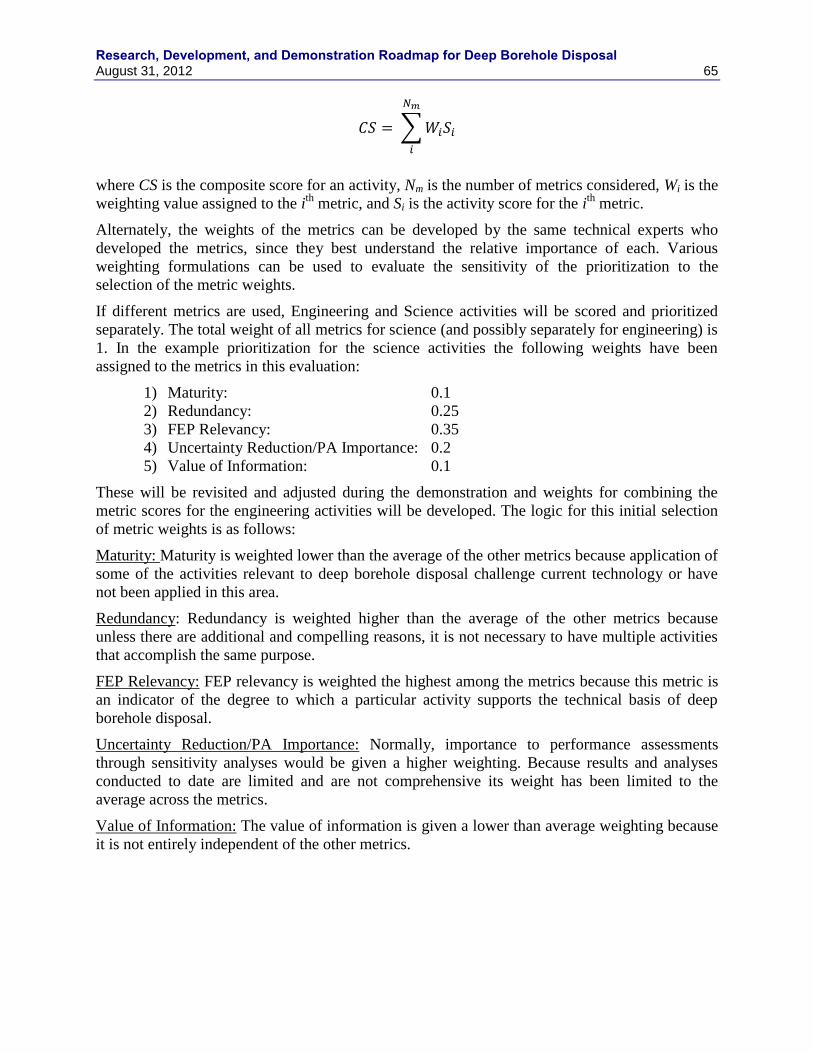
Research, Development, and Demonstration Roadmap for Deep Borehole Disposal August 31, 2012 65
where CS is the composite score for an activity, Nm is the number of metrics considered, Wi is the
weighting value assigned to the ith
metric, and Si is the activity score for the ith
metric.
Alternately, the weights of the metrics can be developed by the same technical experts who
developed the metrics, since they best understand the relative importance of each. Various
weighting formulations can be used to evaluate the sensitivity of the prioritization to the
selection of the metric weights.
If different metrics are used, Engineering and Science activities will be scored and prioritized
separately. The total weight of all metrics for science (and possibly separately for engineering) is
1. In the example prioritization for the science activities the following weights have been
assigned to the metrics in this evaluation:
1) Maturity: 0.1
2) Redundancy: 0.25
3) FEP Relevancy: 0.35
4) Uncertainty Reduction/PA Importance: 0.2
5) Value of Information: 0.1
These will be revisited and adjusted during the demonstration and weights for combining the
metric scores for the engineering activities will be developed. The logic for this initial selection
of metric weights is as follows:
Maturity: Maturity is weighted lower than the average of the other metrics because application of
some of the activities relevant to deep borehole disposal challenge current technology or have
not been applied in this area.
Redundancy: Redundancy is weighted higher than the average of the other metrics because
unless there are additional and compelling reasons, it is not necessary to have multiple activities
that accomplish the same purpose.
FEP Relevancy: FEP relevancy is weighted the highest among the metrics because this metric is
an indicator of the degree to which a particular activity supports the technical basis of deep
borehole disposal.
Uncertainty Reduction/PA Importance: Normally, importance to performance assessments
through sensitivity analyses would be given a higher weighting. Because results and analyses
conducted to date are limited and are not comprehensive its weight has been limited to the
average across the metrics.
Value of Information: The value of information is given a lower than average weighting because
it is not entirely independent of the other metrics.
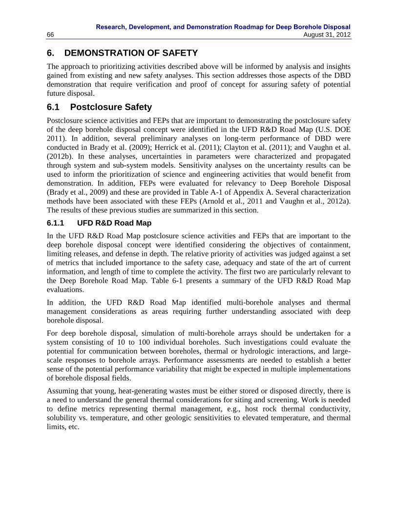
Research, Development, and Demonstration Roadmap for Deep Borehole Disposal
66 August 31, 2012
6. DEMONSTRATION OF SAFETY
The approach to prioritizing activities described above will be informed by analysis and insights
gained from existing and new safety analyses. This section addresses those aspects of the DBD
demonstration that require verification and proof of concept for assuring safety of potential
future disposal.
6.1 Postclosure Safety
Postclosure science activities and FEPs that are important to demonstrating the postclosure safety
of the deep borehole disposal concept were identified in the UFD R&D Road Map (U.S. DOE
2011). In addition, several preliminary analyses on long-term performance of DBD were
conducted in Brady et al. (2009); Herrick et al. (2011); Clayton et al. (2011); and Vaughn et al.
(2012b). In these analyses, uncertainties in parameters were characterized and propagated
through system and sub-system models. Sensitivity analyses on the uncertainty results can be
used to inform the prioritization of science and engineering activities that would benefit from
demonstration. In addition, FEPs were evaluated for relevancy to Deep Borehole Disposal
(Brady et al., 2009) and these are provided in Table A-1 of Appendix A. Several characterization
methods have been associated with these FEPs (Arnold et al., 2011 and Vaughn et al., 2012a).
The results of these previous studies are summarized in this section.
6.1.1 UFD R&D Road Map
In the UFD R&D Road Map postclosure science activities and FEPs that are important to the
deep borehole disposal concept were identified considering the objectives of containment,
limiting releases, and defense in depth. The relative priority of activities was judged against a set
of metrics that included importance to the safety case, adequacy and state of the art of current
information, and length of time to complete the activity. The first two are particularly relevant to
the Deep Borehole Road Map. Table 6-1 presents a summary of the UFD R&D Road Map
evaluations.
In addition, the UFD R&D Road Map identified multi-borehole analyses and thermal
management considerations as areas requiring further understanding associated with deep
borehole disposal.
For deep borehole disposal, simulation of multi-borehole arrays should be undertaken for a
system consisting of 10 to 100 individual boreholes. Such investigations could evaluate the
potential for communication between boreholes, thermal or hydrologic interactions, and large-
scale responses to borehole arrays. Performance assessments are needed to establish a better
sense of the potential performance variability that might be expected in multiple implementations
of borehole disposal fields.
Assuming that young, heat-generating wastes must be either stored or disposed directly, there is
a need to understand the general thermal considerations for siting and screening. Work is needed
to define metrics representing thermal management, e.g., host rock thermal conductivity,
solubility vs. temperature, and other geologic sensitivities to elevated temperature, and thermal
limits, etc.
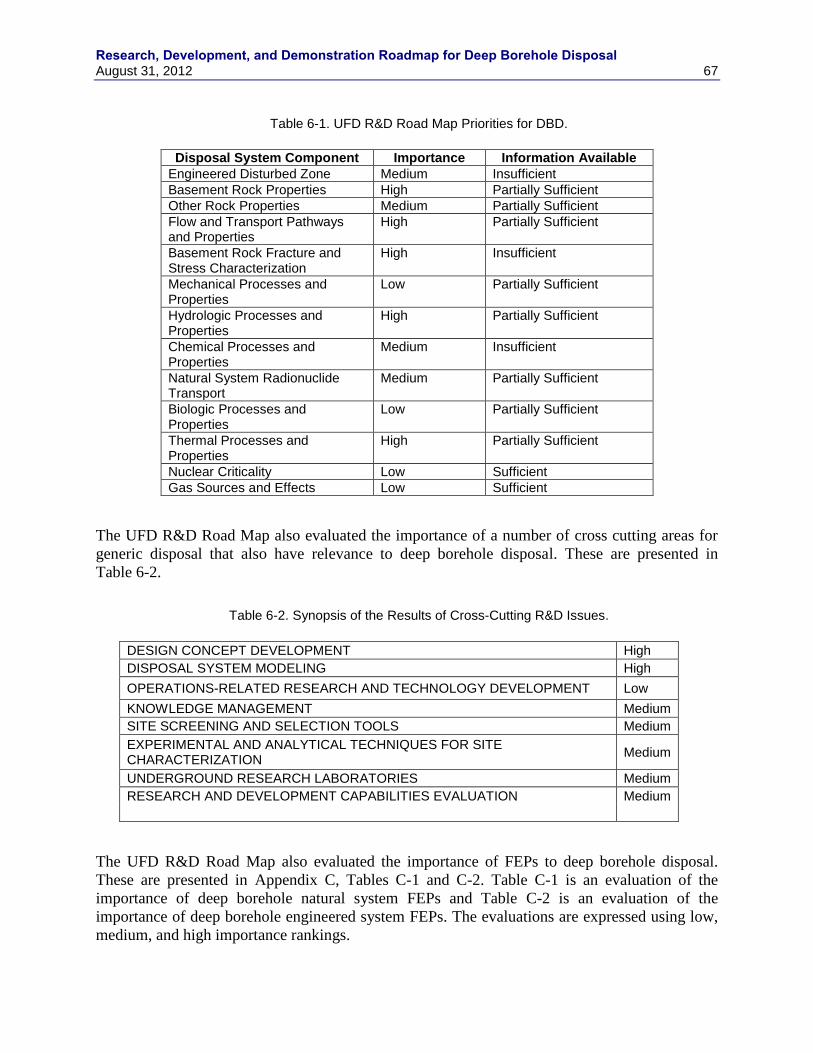
Research, Development, and Demonstration Roadmap for Deep Borehole Disposal August 31, 2012 67
Table 6-1. UFD R&D Road Map Priorities for DBD.
Disposal System Component Importance Information Available
Engineered Disturbed Zone Medium Insufficient
Basement Rock Properties High Partially Sufficient
Other Rock Properties Medium Partially Sufficient
Flow and Transport Pathways and Properties
High Partially Sufficient
Basement Rock Fracture and Stress Characterization
High Insufficient
Mechanical Processes and Properties
Low Partially Sufficient
Hydrologic Processes and Properties
High Partially Sufficient
Chemical Processes and Properties
Medium Insufficient
Natural System Radionuclide Transport
Medium Partially Sufficient
Biologic Processes and Properties
Low Partially Sufficient
Thermal Processes and Properties
High Partially Sufficient
Nuclear Criticality Low Sufficient
Gas Sources and Effects Low Sufficient
The UFD R&D Road Map also evaluated the importance of a number of cross cutting areas for
generic disposal that also have relevance to deep borehole disposal. These are presented in
Table 6-2.
Table 6-2. Synopsis of the Results of Cross-Cutting R&D Issues.
DESIGN CONCEPT DEVELOPMENT High
DISPOSAL SYSTEM MODELING High
OPERATIONS-RELATED RESEARCH AND TECHNOLOGY DEVELOPMENT Low
KNOWLEDGE MANAGEMENT Medium
SITE SCREENING AND SELECTION TOOLS Medium
EXPERIMENTAL AND ANALYTICAL TECHNIQUES FOR SITE CHARACTERIZATION
Medium
UNDERGROUND RESEARCH LABORATORIES Medium
RESEARCH AND DEVELOPMENT CAPABILITIES EVALUATION Medium
The UFD R&D Road Map also evaluated the importance of FEPs to deep borehole disposal.
These are presented in Appendix C, Tables C-1 and C-2. Table C-1 is an evaluation of the
importance of deep borehole natural system FEPs and Table C-2 is an evaluation of the
importance of deep borehole engineered system FEPs. The evaluations are expressed using low,
medium, and high importance rankings.
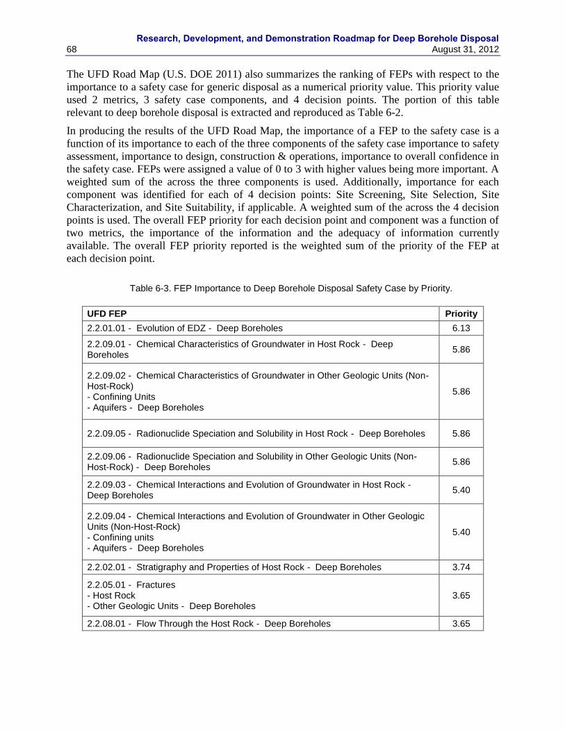
Research, Development, and Demonstration Roadmap for Deep Borehole Disposal
68 August 31, 2012
The UFD Road Map (U.S. DOE 2011) also summarizes the ranking of FEPs with respect to the
importance to a safety case for generic disposal as a numerical priority value. This priority value
used 2 metrics, 3 safety case components, and 4 decision points. The portion of this table
relevant to deep borehole disposal is extracted and reproduced as Table 6-2.
In producing the results of the UFD Road Map, the importance of a FEP to the safety case is a
function of its importance to each of the three components of the safety case importance to safety
assessment, importance to design, construction & operations, importance to overall confidence in
the safety case. FEPs were assigned a value of 0 to 3 with higher values being more important. A
weighted sum of the across the three components is used. Additionally, importance for each
component was identified for each of 4 decision points: Site Screening, Site Selection, Site
Characterization, and Site Suitability, if applicable. A weighted sum of the across the 4 decision
points is used. The overall FEP priority for each decision point and component was a function of
two metrics, the importance of the information and the adequacy of information currently
available. The overall FEP priority reported is the weighted sum of the priority of the FEP at
each decision point.
Table 6-3. FEP Importance to Deep Borehole Disposal Safety Case by Priority.
UFD FEP Priority
2.2.01.01 - Evolution of EDZ - Deep Boreholes 6.13
2.2.09.01 - Chemical Characteristics of Groundwater in Host Rock - Deep Boreholes
5.86
2.2.09.02 - Chemical Characteristics of Groundwater in Other Geologic Units (Non-Host-Rock) - Confining Units - Aquifers - Deep Boreholes
5.86
2.2.09.05 - Radionuclide Speciation and Solubility in Host Rock - Deep Boreholes 5.86
2.2.09.06 - Radionuclide Speciation and Solubility in Other Geologic Units (Non-Host-Rock) - Deep Boreholes
5.86
2.2.09.03 - Chemical Interactions and Evolution of Groundwater in Host Rock - Deep Boreholes
5.40
2.2.09.04 - Chemical Interactions and Evolution of Groundwater in Other Geologic Units (Non-Host-Rock) - Confining units - Aquifers - Deep Boreholes
5.40
2.2.02.01 - Stratigraphy and Properties of Host Rock - Deep Boreholes 3.74
2.2.05.01 - Fractures - Host Rock - Other Geologic Units - Deep Boreholes
3.65
2.2.08.01 - Flow Through the Host Rock - Deep Boreholes 3.65
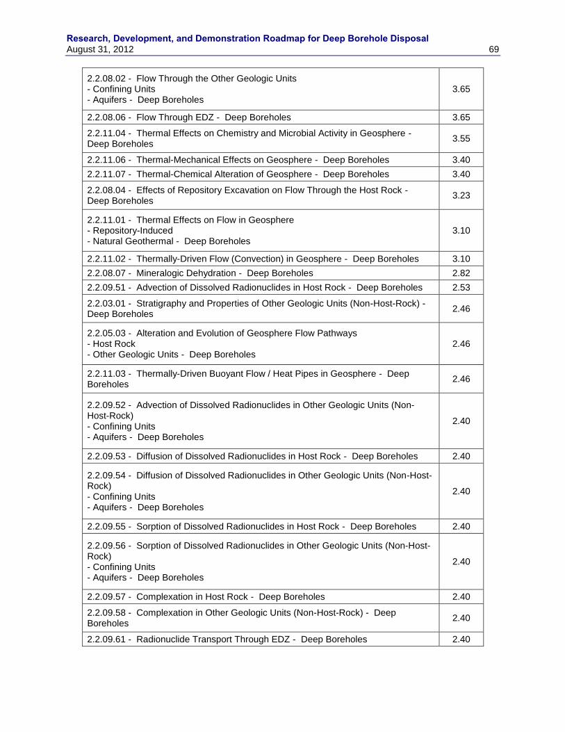
Research, Development, and Demonstration Roadmap for Deep Borehole Disposal August 31, 2012 69
2.2.08.02 - Flow Through the Other Geologic Units - Confining Units - Aquifers - Deep Boreholes
3.65
2.2.08.06 - Flow Through EDZ - Deep Boreholes 3.65
2.2.11.04 - Thermal Effects on Chemistry and Microbial Activity in Geosphere - Deep Boreholes
3.55
2.2.11.06 - Thermal-Mechanical Effects on Geosphere - Deep Boreholes 3.40
2.2.11.07 - Thermal-Chemical Alteration of Geosphere - Deep Boreholes 3.40
2.2.08.04 - Effects of Repository Excavation on Flow Through the Host Rock - Deep Boreholes
3.23
2.2.11.01 - Thermal Effects on Flow in Geosphere - Repository-Induced - Natural Geothermal - Deep Boreholes
3.10
2.2.11.02 - Thermally-Driven Flow (Convection) in Geosphere - Deep Boreholes 3.10
2.2.08.07 - Mineralogic Dehydration - Deep Boreholes 2.82
2.2.09.51 - Advection of Dissolved Radionuclides in Host Rock - Deep Boreholes 2.53
2.2.03.01 - Stratigraphy and Properties of Other Geologic Units (Non-Host-Rock) - Deep Boreholes
2.46
2.2.05.03 - Alteration and Evolution of Geosphere Flow Pathways - Host Rock - Other Geologic Units - Deep Boreholes
2.46
2.2.11.03 - Thermally-Driven Buoyant Flow / Heat Pipes in Geosphere - Deep Boreholes
2.46
2.2.09.52 - Advection of Dissolved Radionuclides in Other Geologic Units (Non-Host-Rock) - Confining Units - Aquifers - Deep Boreholes
2.40
2.2.09.53 - Diffusion of Dissolved Radionuclides in Host Rock - Deep Boreholes 2.40
2.2.09.54 - Diffusion of Dissolved Radionuclides in Other Geologic Units (Non-Host-Rock) - Confining Units - Aquifers - Deep Boreholes
2.40
2.2.09.55 - Sorption of Dissolved Radionuclides in Host Rock - Deep Boreholes 2.40
2.2.09.56 - Sorption of Dissolved Radionuclides in Other Geologic Units (Non-Host-Rock) - Confining Units - Aquifers - Deep Boreholes
2.40
2.2.09.57 - Complexation in Host Rock - Deep Boreholes 2.40
2.2.09.58 - Complexation in Other Geologic Units (Non-Host-Rock) - Deep Boreholes
2.40
2.2.09.61 - Radionuclide Transport Through EDZ - Deep Boreholes 2.40
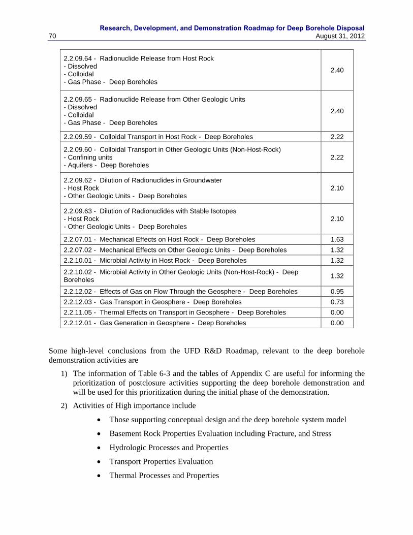
Research, Development, and Demonstration Roadmap for Deep Borehole Disposal
70 August 31, 2012
2.2.09.64 - Radionuclide Release from Host Rock - Dissolved - Colloidal - Gas Phase - Deep Boreholes
2.40
2.2.09.65 - Radionuclide Release from Other Geologic Units - Dissolved - Colloidal - Gas Phase - Deep Boreholes
2.40
2.2.09.59 - Colloidal Transport in Host Rock - Deep Boreholes 2.22
2.2.09.60 - Colloidal Transport in Other Geologic Units (Non-Host-Rock) - Confining units - Aquifers - Deep Boreholes
2.22
2.2.09.62 - Dilution of Radionuclides in Groundwater - Host Rock - Other Geologic Units - Deep Boreholes
2.10
2.2.09.63 - Dilution of Radionuclides with Stable Isotopes - Host Rock - Other Geologic Units - Deep Boreholes
2.10
2.2.07.01 - Mechanical Effects on Host Rock - Deep Boreholes 1.63
2.2.07.02 - Mechanical Effects on Other Geologic Units - Deep Boreholes 1.32
2.2.10.01 - Microbial Activity in Host Rock - Deep Boreholes 1.32
2.2.10.02 - Microbial Activity in Other Geologic Units (Non-Host-Rock) - Deep Boreholes
1.32
2.2.12.02 - Effects of Gas on Flow Through the Geosphere - Deep Boreholes 0.95
2.2.12.03 - Gas Transport in Geosphere - Deep Boreholes 0.73
2.2.11.05 - Thermal Effects on Transport in Geosphere - Deep Boreholes 0.00
2.2.12.01 - Gas Generation in Geosphere - Deep Boreholes 0.00
Some high-level conclusions from the UFD R&D Roadmap, relevant to the deep borehole
demonstration activities are
1) The information of Table 6-3 and the tables of Appendix C are useful for informing the
prioritization of postclosure activities supporting the deep borehole demonstration and
will be used for this prioritization during the initial phase of the demonstration.
2) Activities of High importance include
Those supporting conceptual design and the deep borehole system model
Basement Rock Properties Evaluation including Fracture, and Stress
Hydrologic Processes and Properties
Transport Properties Evaluation
Thermal Processes and Properties
Research, Development, and Demonstration Roadmap for Deep Borehole Disposal August 31, 2012 71
3) Activities of Moderate importance include
EDZ Properties (more recent assessments indicate that this is of high
importance)
Chemical Processes and Properties
4) Activities of Low importance include
Nuclear Criticality
Gas Sources and Effects
Biologic Processes and Properties
The UFD R & D Road Map is in the process of being revised, so the above evaluation may
change.
6.1.2 Existing Postclosure Analyses in Support of Activity Prioritization
This section presents a synthesis of the existing deep borehole disposal postclosure safety
assessments and sensitivity analyses that provide risk based information in support of the
prioritization. These analyses were conducted by Brady et al., 2009; Herrick et al., 2011; and
Vaughn et al., 2012b). Current analyses have been limited to undisturbed (in the absence of
external events) performance.
6.1.2.1 Deep Borehole Disposal of High-Level Radioactive Waste (Brady et al., 2009)
A preliminary safety assessment using an analytical solution of the advection-diffusion equation
was conducted in Brady et al., 2009 conditioned on thermal-hydrologic calculations. These DB-
PA results are based on several bounding and conservative assumptions, such as: all waste is
assumed to instantly degrade and dissolve inside the waste canisters; all waste is assumed to be
PWR assemblies; no credit is taken for sorption or decay along the saturated zone transport
pathway from the sealed borehole to the withdrawal well assumed to take 8,000 years.
Some high-level conclusions from Brady et al., 2009, relevant to the deep borehole
demonstration activities are
1) The coupled thermal-hydrologic-chemical-mechanical behavior of the borehole and
disturbed region during the thermal pulse, and in the presence of density-stratified waters,
should be modeled more accurately.
a. High PA metric rating for science activities: Temperature Log, Waste Canister
Mockup Electrical Heater Test, Fluid Samples from Packer Testing, Drill
Cuttings, Intermittent Coring, Chemical Equilibrium Modeling, TH modeling,
Conceptual Model Design, Numerical Model Implementation of Sub-Models,
Construction of System Model
b. Medium PA metric rating for Science Activities: Chemical Kinetics Modeling
2) Additional consideration should be focused on the design and long-term performance of
deep seals.
a. High PA metric rating for Science activities: Fluid Samples from Packer Testing,
Seals Integrity Testing and Cement Degradation Testing and Engineering
Research, Development, and Demonstration Roadmap for Deep Borehole Disposal
72 August 31, 2012
activities: Demonstration of Casing Emplacement, Demonstration of Liner
Emplacement, Bentonite Seal Emplacement, Cement Seal Emplacement.
3) Modeling of both the full-system performance of multi-borehole arrays should be
undertaken, consistent with an assumption that a regional borehole disposal facility could
entail an array of 10-100 individual boreholes.
a. Moderate PA metric rating for Science activities: Multi-well Hydraulic Testing,
Cross-hole Tomography, Multi-Borehole Modeling.
6.1.2.2 Deep Borehole Seals (Herrick et al., 2011)
A preliminary performance assessment model for the deep borehole disposal system was used to
analyze the relationship between the effectiveness of the borehole seals and risk to human health
using Monte Carlo sampling for propagating uncertainty. The objective of this analysis was to
determine the maximum effective permeability of the borehole seals and the surrounding
disturbed rock zone (DRZ) that would result in an allowable level of risk, as estimated by
radiological dose. 5 cases were evaluated.
Some high-level conclusions from Herrick et al., 2011, relevant to the deep borehole
demonstration activities are
1) Heat load is a driver for upward flow of fluids and thermal conduction into surrounding
host rock greatly dominates heat transfer mechanisms
a. High PA metric rating for Science activities: Source Term Modeling, TH
Modeling, Construction of System Model, Waste Canister Mockup Electrical
Heater Test, Temperature Log, Drill Cuttings, Intermittent Coring
2) Upward flow rapidly diminishes with distance above the disposal zone
a. High PA metric rating for Science activities
3) Seal permeabilities on the order of 10-16
m2 are sufficient to limit releases and integrity is
a dominate driver for releases to AE
a. High PA metric rating for Science activities: Fluid Samples from Packer Testing,
Seal Integrity Testing, Cement Degradation Testing and Engineering activities:
Demonstration of Casing Emplacement, Demonstration of Liner emplacement,
Bentonite Seal Emplacement, Cement Seal Emplacement
4) 129
I dominates radioactive releases and sorption of 129
I greatly reduces or eliminates
release
a. High PA metric rating for Science activities: Source Term Modeling, Chemical
Equilibrium Modeling, Fluid Samples from Packer Testing, Radionuclide
Characterization, Seal Zone Sorbent Testing
6.1.2.3 Generic Disposal System Modeling Fiscal Year 2011 Progress Report (Clayton et al., 2011)
A preliminary safety assessment and some supporting system and sub-system sensitivity
analyses of deep borehole disposal were conducted. In these analyses, uncertainties in parameters
were characterized and propagated through system and sub-system models using Monte Carlo
Research, Development, and Demonstration Roadmap for Deep Borehole Disposal August 31, 2012 73
sampling of the uncertain parameter distributions. The flow rate histories were obtained from
detailed thermal hydrologic process-level results and coupled to the system model.
Conclusions from the Clayton et al., 2011 analyses relevant to prioritization of deep borehole
demonstration activities, the following can be learned:
1) Diffusion dominates transports in the base case while advection dominants when seals
performance degrades
a. High PA metric rating for Science activities: Drill Cuttings, Intermittent Coring
2) Proper emplacement of seal components and their long term behavior are important even
under failed seal conditions, potential dose are well below current regulatory standards
a. High PA metric rating for Science activities: Fluid Samples from Packer Testing,
Seal Integrity Testing, Cement Degradation Testing and Engineering activities:
Demonstration of Casing emplacement, Demonstration of Liner emplacement,
Bentonite Seal Emplacement, Cement Seal Emplacement
3) The use of iodine sorbent in the seal zone is quite effective
a. High PA metric rating for Science activities: Source Term Modeling, Chemical
Equilibrium Modeling, Fluid Samples from Packer Testing, Radionuclide
Characterization, Seal Zone Sorbent Testing
4) Eliminating or reducing causes for upward flow is important in the event of seal failure
a. High PA metric rating for Science activities: Fluid Samples from Packer Testing,
Seal Integrity Testing, Cement Degradation Testing and Engineering activities:
Demonstration of Casing emplacement, Demonstration of Liner emplacement,
Bentonite Seal Emplacement, Cement Seal Emplacement, Source Term
Modeling, TH modeling, Construction of System Model, Waste Canister Mockup
Electrical Heater Test, Temperature Log, Drill Cuttings, Intermittent Coring.
6.1.2.4 Draft Generic Deep Geologic Disposal Safety Case (Vaughn et al., 2012b)
A preliminary safety assessment and some supporting system and sub-system sensitivity
analyses of deep borehole disposal were conducted in Vaughn et al., 2012b. In these analyses, a
set of “one-off,” ceirtus paribus, simulations were performed where selected parameter were
varied while holding all others at baseline values.
The following observations from the Vaughn et al., 2012b analyses can be made regarding the
performance of a generic deep borehole disposal system:
1) Waste form degradation impacts dose rate to a receptor in the EA
a. High PA metric rating for Science activities: Source Term Modeling, Fluid
Samples from Packer Testing, Waste Form Degradation Testing
2) Processes and parameters affecting radionuclide transport through the seal zone can
have a significant effect on annual dose. These include sorption, Kd, seal zone
integrity, and molecular diffusivity.
a. High PA metric rating for Science activities: Source Term Modeling,
Chemical Equilibrium Modeling, Fluid Samples from Packer Testing,
Radionuclide Characterization, Seal Zone Sorbent Testing, Seal Integrity
Testing, Cement Degradation Testing and Engineering activities:

Research, Development, and Demonstration Roadmap for Deep Borehole Disposal
74 August 31, 2012
Demonstration of Casing emplacement, Demonstration of Liner emplacement,
Bentonite Seal Emplacement, Cement Seal Emplacement, Drill Cuttings,
Intermittent Coring
3) Diffusion dominates the transport although if seals degrade advection can become
important. Advective flow is influenced by thermal considerations.
a. High PA metric rating for Science activities: Source Term Modeling, TH
modeling, Construction of System Model, Waste Canister Mockup Electrical
Heater Test, Temperature Log, Drill Cuttings, Intermittent Coring
Research, Development, and Demonstration Roadmap for Deep Borehole Disposal August 31, 2012 75
7. LEGAL AND REGULATORY FRAMEWORK
Legal and regulatory issues and requirements will be addressed for the DBD demonstration
project during the site selection process. This will allow specific state and local requirements to
be evaluated and managed. The legal and regulatory framework for DBD disposal of SNF and
HLW will be addressed in subsequent work.
7.1 Demonstration
Regulatory preparations will be initiated at the start of the site selection process and continued
through the technical planning and drilling of the demonstration borehole. The regulatory
environment is different in different states and for Federal versus private land. Experience has
shown that acquiring permits often results in project delays and is responsible for changes in
borehole design. Since the demonstration borehole will be unique, in terms of both size and
purpose, it is important that regulatory agencies be presented with realistic plans that take into
account existing regulations. There is a possibility in unique situations such as that presented by
a DBD demonstration project that regulators may be overly cautious.
7.1.1 Local, State, and Federal Permits
These permits will vary by location, but it is important to define the operator of the
demonstration borehole who will be the responsible party. Permitting may require the posting of
bonds.
7.1.2 Drilling Permits
The request for a drilling permit will generally require that a borehole plan be submitted.
Regulators will be interested in seeing a casing program that isolates aquifers and assures
effective control of down-hole pressure (Blow-Out Prevention System). They will also be
interested in the mud system and containment and disposal of drill cuttings.
7.1.3 Air Quality Permits
Air quality permits may be required for the drilling operation since this represents a point source
for emissions. Some states are much more restrictive than others and may require Tier 3 engines
on the rig and associated power units meet strict emission guidelines.
7.1.4 Land/Water Use Permits
Land use permits will be required on public lands; whereas land owner agreements and leases
will be required on private lands. In many instances, the surface and subsurface rights may be
separate. The drilling operation will consume large amounts of water; therefore it is likely that a
water well will be drilled on location to eliminate the use of water hauls. This water well, if
required, will be permitted through the appropriate state‟s division of water rights.
7.2 National Environmental Policy Act Compliance
As a Federally funded project, compliance with the National Environmental Policy Act (NEPA)
is a requirement. Some uncertainty exists regarding the level of effort required to comply. It
appears unlikely that a categorical exclusion would be granted. The project scope and duration is
not of a magnitude that would generally require an Environmental Impact Statement, so for our
planning purpose we have included time and money to perform an Environmental Assessment.
In the near future we will complete an Environmental Checklist and discuss our findings with the

Research, Development, and Demonstration Roadmap for Deep Borehole Disposal
76 August 31, 2012
Sandia Site Office, NEPA Compliance Officer. This discussion will allow us to finalize our
NEPA compliance strategy.
Research, Development, and Demonstration Roadmap for Deep Borehole Disposal August 31, 2012 77
8. SITE SELECTION/DEMONSTRATION PROJECT
This section discusses the RD&D data gaps associated with choosing the location for a DBD
demonstration project and the eventual selection of a site for deployment of the DBD system.
The focus will be on a process that locates the demonstration borehole at a site that is
representative of the geology and other characteristics in which future DBD might be carried out.
Selection guidelines are aimed at avoiding locations with potentially unfavorable conditions for
DBD, such as overpressured conditions or high geothermal gradient. In addition to the technical
siting factors, this section also discusses the socio-political factors and public outreach program
that are relevant to successfully siting and implementing the DBD demonstration project.
8.1 Siting Process
The demonstration project team will develop a siting process that embraces the principles
outlined in the Blue Ribbon Commission on America‟s Nuclear Future recommendations. Even
though this demonstration project will not involve nuclear waste, we believe the siting principles
should be utilized to the greatest extent practical to maximize the success of the project. These
principles include
Consent-based - in the sense that affected communities have an opportunity to decide
whether to accept facility siting decisions and retain significant local control.
Transparent - in the sense that all stakeholders have an opportunity to understand key
decisions and engage the process in a meaningful way.
Phased - in the sense that key decisions are revisited and modified as necessary along the
way rather than being pre-determined.
Adaptive - in the sense that process itself is flexible and produces decisions that are
responsive to new information and new technical, social, or political developments.
Standards-and science-based - in the sense that the public can have confidence that all
facilities meet rigorous, objective, and consistently-applied standards of safety and
environmental protection.
Governed by partnership arrangements or legally-enforceable agreements between the
implementing organization and host states, tribes, and local communities.
Representative Site – that the selected site or sites be representative in terms of features,
events, and processes important to disposal.
The recommended approach for identifying the location of the DBD demonstration project
includes the following steps. Existing data will be analyzed by the project team to determine
several regional or sub-regional areas that exhibit technical characteristics that are favorable to
DBD, in terms of the science thrust and the engineering thrust of the RD&D demonstration plan,
as described in Section 8.2. Potential stakeholders in the scientific and drilling engineering
communities will be engaged in assessing the viability of pursuing the DBD demonstration
project in different geographic areas. Such stakeholders may include regional university faculty,
state geological surveys, and regional drilling and service contractors. State and local
stakeholders in the political and economic arena will be engaged in determining the social
viability of the demonstration project after a supporting consensus has been formed by the
scientific and engineering communities. Selection of a specific site for the potential DBD
Research, Development, and Demonstration Roadmap for Deep Borehole Disposal
78 August 31, 2012
demonstration project would consider a number of factors, including land ownership, permitting
issues, local availability of supporting services, proximity to project participants, and potential
importance and/or impacts to natural resources. Surface-based characterization methods would
be used at a specific site prior to a go/no go decision on the drilling for the demonstration
project.
Site selection for a deep borehole disposal site would be a more complex process than the siting
process for the DBD demonstration project for a number of reasons. Actual disposal of nuclear
waste would likely be much more controversial activity from a social and political perspective
than the DBD demonstration project. In this sense, site selection for DBD program would
involve a more extensive stakeholder outreach program and more complex political engagement
than locating the DBD demonstration project. Site selection for a DBD facility would also
involve consideration of waste transportation costs and infrastructure, which could vary
considerably depending on the disposal site location relative to waste storage or nuclear power
plant locations. A DBD facility would also require a larger site and a longer-term commitment
than the DBD demonstration project, which would be important considerations in the site
selection process.
8.2 Site Selection Guidelines
As part of the science and engineering thrust of this project, a set of basic initial technical siting
guidelines will be established to ensure successful deep borehole disposal. These guidelines will
focus on technical elements that are representative of potential future sites for DBD and
conditions favorable for waste disposal in the deep subsurface.
8.2.1 Technical Guidelines Related to the Science Thrust
This section discusses factors related to the science thrust that could be evaluated prior to drilling
regarding suitability and representativeness of the demonstration site, based on regional
geological and hydrological data. Emphasis will be placed on evaluating characteristics that, if
present, would be unfavorable to long-term safety of DBD. Although actual waste disposal is not
a part of the demonstration project, RD&D activities should be conducted at a site that has
characteristics representative of and consistent with implementation and safety of the DBD
concept. This provides some assurance that what is learned during the demonstration project is
transferrable to other similar locations favorable to DBD. Factors discussed include depth to
crystalline basement rocks, deep groundwater circulation, tectonically unstable conditions,
overpressured fluids at depth, major faults, volcanism, high geothermal heat flow, and potential
for economically valuable mineral deposits.
Technical factors in the science thrust that are potentially important to waste isolation in the
DBD concept and to the successful implementation of the DBD demonstration project include
Depth to crystalline basement
Crystalline basement lithology
Basement geological structural complexity
Topographic relief within 100 to 200 km of site
Geothermal gradient
Geothermal heat flux
Research, Development, and Demonstration Roadmap for Deep Borehole Disposal August 31, 2012 79
Petroleum exploration and production
Mineral resources
Tectonic activity and seismicity
Faults
Volcanism
A depth of less than 2,000 m to the crystalline basement allows for a 2,000 m disposal zone and
a 1,000 m thick seal zone in the crystalline basement for the DBD demonstration project
borehole (see, for example, Figure 2 in Brady et al., 2009). These conditions are consistent with
the DBD concept. Areas with regional geological structural complexity, particularly in the
western U.S., have a higher uncertainty in the depth to crystalline basement at some specific
locations. Such structural complexity is also broadly associated with geologically recent tectonic
activity, seismicity, and higher topographic relief. Crystalline basement lithology is variable, but
broad patterns of age and rock type have been identified for Precambrian terrain that is covered
by Phanerozoic-age sedimentary rocks. Granite or granitic gneissic rocks are preferred for the
DBD concept. Major structural features, faults, and formerly tectonically active zones, such as
the Precambrian-age midcontinent rift (Ojakangas et al., 2001), are generally potentially
unfavorable for DBD because of possible enhanced crustal-scale permeability and non-
crystalline rock types in the Precambrian basement.
Vertical and horizontal groundwater hydraulic gradients in the deep subsurface are generally
related to regional variations in topographic elevation. Topographically driven groundwater flow
can extend to great depths and long distances under some hydrogeological conditions, leading to
overpressured conditions and the potential for upward flow in regional discharge areas.
Proximity to significant variations in topographic elevation (i.e., slope) is a generally
unfavorable condition for DBD and for the deep borehole demonstration project, although deep
groundwater can be isolated and stagnant in some hydrogeologic settings, in spite of topographic
effects.
High geothermal heat flow is related to the potential for deep geothermal energy development
and possible human intrusion by drilling into the crystalline basement. High geothermal heat
flow may also be related to the potential for overpressured conditions at depth and upward
hydraulic gradients. Because of these factors areas with high geothermal heat flow are
considered generally unfavorable for the DBD demonstration project.
The potential for human intrusion at a site would be unfavorable for DBD and waste isolation.
Exploration for petroleum resources would be limited to sedimentary rocks overlying the
crystalline basement, with the potential exception of locations where Precambrian rocks have
been thrust over the sedimentary section. Extensive development of petroleum resources in
sedimentary rocks overlying the crystalline basement might impact the release of radionuclides
from DBD in some scenarios. Mineral resources at the depths of DBD in the crystalline
basement are generally beyond the reach of current mineral exploration activities; however,
exceptional cases of such resources potentially could be economically exploited at depths of
several thousand meters. Information on the potential for mineral resources that would be useful
in the DBD demonstration project site selection generally does not exist. Surface-based
geophysical methods might provide indications of potential mineral resources in some cases, but
are unlikely to do so.
Research, Development, and Demonstration Roadmap for Deep Borehole Disposal
80 August 31, 2012
High seismic hazard would present somewhat higher risks during drilling and waste
emplacement operations; however, these risks could be mitigated through engineering solutions.
Seismic hazard is a very general indicator of tectonic activity, risk of borehole shearing by fault
movement, and geological structural complexity. Additionally, because emplaced waste
packages are highly confined by the borehole walls, they would not be expected to be subject to
displacement and damage during seismic events. Faulting and potential for volcanism can be
assessed from surface geological mapping.
Evaluation of many of these factors can be accomplished on a preliminary, regional basis with
existing data. An accurate compilation of relevant data can be made using a geographical
information system (GIS) database, and such activities are underway as part of the UFD
Campaign efforts in assessing regional geology for alternative disposal system concepts.
8.2.2 Technical Guidelines Related to the Engineering Thrust
The DBD demonstration borehole should be located in an area where the geology and drilling
environment are well known. The geology will influence the casing and drilling programs. Past
drilling experience will assist in identifying drilling issues that are the sources of uncertainty and
cost. To reduce operational cost, the proximity to drilling equipment and supplies will be a
consideration for site selection. Previous drilling history for an area will allow definition of
casing points, identification of potential drilling problem zones, evaluation of potential
overpressures, and occurrences of hydrocarbons.
It is anticipated that additional geophysical surveys may be required prior to selecting a location
for the DBD demonstration project. Seismic reflection can be used to determine the stratigraphy
and in particular the depth to crystalline basement. It should also be used to verify the absence of
faults. The sedimentary cover should be relatively flat to aid in keeping the borehole vertical.
Seismic monitoring should be conducted prior to drilling to provide a baseline and verify the
absence of seismic activity. From an operational standpoint, an area with a moderate climate
should be selected. From a postclosure safety standpoint this is not a significant consideration.
On deep scientific drilling projects, pilot holes are often drilled to evaluate the geologic
environment and drilling conditions in advance of a more expensive large diameter hole. The
technology is available to continuously core the isolation zone (Nielson 2001). This type of
drilling provides continuous samples that can be subjected to petrologic and physical property
determinations. These boreholes can also be instrumented for long term monitoring of
temperature and fluids.
8.3 Stakeholder Outreach
Experience indicates that project success is strongly influenced by stakeholder participation. This
section of the report identifies and evaluates the appropriate involvement of all the stakeholder
groups during the development of the project. In addition, it is expected that the process of
construction and post-construction phases of the project will have a significant
stakeholder/public access component. Much of the stakeholder outreach implementation will be
covered by the Communication Management Plan covered in the Business Management section
of this plan.
The general strategy for siting the DBD demonstration project is a staged and adaptive approach.
The strategy also seeks to obtain input from multiple interested parties, with the ultimate goal of
Research, Development, and Demonstration Roadmap for Deep Borehole Disposal August 31, 2012 81
achieving support from key stakeholders. A process similar to that used in selecting sites for
deep scientific drilling projects would be employed.
The first step in the siting process for the demonstration project would be regional evaluations of
relevant guidelines, as described in Section 8.2. From these evaluations several candidate
regional or sub-regional areas could be identified for further consideration. Communication with
potentially interested stakeholders in the area of scientific investigations, such as regional
universities and state geological surveys would be initiated to assess receptiveness to
participating in the DBD demonstration project. In addition, opinions on siting from the much
broader international deep scientific drilling community would be sought. Engagement with
regional drilling and services companies would be used to alert private industry to the nature of a
demonstration project and to gather information on the local availability of such resources.
Outreach to state and local political entities would be initiated in favorable regional or sub-
regional areas, ideally with the support of scientific investigations and business stakeholders.
Such outreach would seek to communicate the nature, scope, and benefits of the DBD
demonstration project, including uses of the facility after completion of the demonstration, and to
solicit feedback on the political and social viability of the project in a given area.

Research, Development, and Demonstration Roadmap for Deep Borehole Disposal
82 August 31, 2012
9. BUSINESS MANAGEMENT
A sound business management plan (Project Management Plan/Project Execution Plan) will be
prepared for this project. The Plan will be an evolving document that describes the key elements
of our business planning, outlining the processes, skills, tools and techniques we will implement
to ensure the success of this project. We anticipate that after the DOE formally declares the
activity a “project,” under the requirements of DOE O 413, “Program and Project Management
for the Acquisition of Capital Assets,” a Project Execution Plan will be prepared.
9.1 Project Team and Organizational Structure
The project team will comprise various organizations from National Laboratories, industry and
academia. International collaborations will also be important. Under the authority of the
Department of Energy, Sandia National Laboratories will be the lead organization and it will be
supported by individuals from other organizations that have people with the needed skills for the
particular activity to be managed and/or performed. Appropriate people will be identified and
roles and responsibilities will be clearly assigned to ensure successful completion of the project.
The organizational structure of the DBD Project Team will reflect the three major functional
components of the demonstration project: (1) drilling and construction, (2) scientific
investigations, and (3) engineering demonstration. These components will be well integrated and
frequent interactions will be held to manage and resolve potential conflicts among these groups
during the demonstration project. A formalized structure and process will be established for
communication, coordination and prioritization of activities among these components.
9.2 Project Execution and Management Plan
When appropriate, in accordance with DOE O 413, a Project Execution/Project Management
Plan will be prepared to document the actions and processes necessary to define, prepare,
integrate, and coordinate all project activities and plans. The plan will define how the project is
executed, monitored and controlled, and completed. The project team will direct the performance
of the planned project activities, and manage the various technical and organizational interfaces
that exist within the project. It will include the coordination of all elements of drilling, logging,
testing, and engineering involved in the project.
9.3 Work Breakdown Structure
As shown in Appendix D, a high-level, work breakdown structure (WBS) has been prepared to
subdivide the project deliverables and project work into smaller, more manageable components.
As greater detail is established for the project, the WBS will be modified to add additional levels
of detail. All the planned work will be contained within the WBS components, and the lowest
level of the WBS will be designated as work packages and encompass and define the total scope
of work for the project.
9.4 Cost Management
The Project Cost Management will be included in the Project Execution Plan and it will be
refined as the project evolves. When the project is fully defined the total project cost will be the
aggregation of the estimated costs of individual activities or work packages and this estimate will
establish an authorized cost baseline or budget. The project cost will be monitored at the work
package level through-out the project life and required changes will be managed to control the
Research, Development, and Demonstration Roadmap for Deep Borehole Disposal August 31, 2012 83
cost baseline. The preliminary cost estimate for this project is $75M, as shown in Appendix E.
This estimate will be refined as more project details are known.
9.5 Project Schedule
The project schedule is presented in Appendix F. This schedule assumes an October 1, 2012 start
and will be modified, as appropriate, when DOE funding profile and authorization is received.
As the project evolves greater detail will be added with specific planned start and finish dates for
all project activities (the lowest level of the WBS) and milestones. An approved project schedule
will serve as a baseline to track progress and it will be maintained through-out the project as
work progresses.
9.6 Communications Management
A Communication Management Plan will be prepared, in conjunction with the Project Execution
Plan and Site Selection, to include the processes required for ensuring timely and appropriate
generation, collection, distribution, storage, retrieval, and ultimate disposition of project
information. Effective communication will create a bridge between diverse stakeholders
involved in the project, connecting various cultural and organizational backgrounds, different
levels of expertise, and various perspectives and interests in the project execution or outcome.
9.7 Project Risk Assessment
Drilling has some risk largely because of unknown conditions in the subsurface. Drilling plans
deal with risk by applying contingency factors to different budget components. Risk is also
mitigated by employing experienced personnel and assuring that the best expertise is present
during critical activities in the borehole construction process.
As part of the Project Execution Plan, the project team will include a risk management section,
which will include the processes of conducting risk management planning, identification,
analysis, response planning, monitoring and control. The objectives of Project Risk Management
will be to increase the probability and impact of positive events, and decrease the probability and
impact of negative events in the project.
9.8 Quality Assurance
Work performed under this Plan is subject to the quality assurance (QA) and quality control
(QC) programs and requirements of DOE Orders. The demonstration project for DBD will
generate a considerable amount of data and probably a large volume of samples. The technical
and scientific conclusions of the project will be based on this information. Appropriate quality
assurance procedures for analysis and documentation are essential and will be followed. In
addition, protocols for collection and storage of data and samples must be established before the
project gets underway. An important part of a QA/QC program also concerns the drilling
equipment and supplies that are used on the project. Specifications should be carefully set during
the planning and procurement process. An inspection program must insure that the supplies and
components received achieve the required standards.
Research, Development, and Demonstration Roadmap for Deep Borehole Disposal
84 August 31, 2012
10. LONG-TERM USE AND MAINTENANCE
The details of long-term use and maintenance of the facility will be evaluated as the project is
sited and developed. Since the demonstration will result in a significant investment and will
result in a potentially valuable facility, it is important to consider potential long-term uses of the
facility. The potential for long term use depends on a number of factors, especially the end state
of the facility at the conclusion of the demonstration:
If seals testing must be demonstrated in the deep borehole, this will involve emplacement
of materials and sealing of at least a portion of the borehole. If and how this is done may
compromise the most potentially useful and valuable asset of the demonstration: the deep
borehole itself.
The condition of the surface including the deposition of the drill cuttings will require
restoration, which must be identified along with how that restoration can contribute to
end use.
The end state of the surface and subsurface components of the various characterization
techniques requiring testing during the demonstration needs to be described. These are
potentially valuable assets contributing to the usefulness of the facility after
demonstration.
The fate of the drilling rig and specialized waste canister emplacement rig (if needed)
will need to be decided upon and may contribute to the long-term usefulness of the
facility.
The surface support facilities including utility services also contributes to long-term use
and consideration of how these can be adapted to support long-term use will be required.
There are a number of possibilities with respect to long-term facility use. Because of multiple
uncertainties (e.g., end-state uncertainties, political and regulatory at this time, etc.), it is prudent
to evaluate a suite of options during the demonstration process rather than focus on a single
expected path forward for future use. Possible use options after the demonstration will be
identified, evaluated, and included in the planning process.
The likely spectrum of options will be bound by (1) closure, restoration, and walk away option
and (2) long-term use as a RD&D “underground” laboratory for geosciences, hydrology, and
other sciences.
Research, Development, and Demonstration Roadmap for Deep Borehole Disposal August 31, 2012 85
11. SUMMARY
A successful DBD demonstration project will increase the disposal options available to the
United States. Deep Borehole Disposal of HLW and SNF is a potentially robust disposal option
which offers cost-effective disposal and other advantages over repository disposal but still
remains unconfirmed, unlike disposal in geologic repositories. This roadmap establishes the
technical and programmatic basis for fielding a full-scale DBD project. The roadmap includes
identification of science and engineering needs and gaps, use of risk informed methods,
regulatory and legal considerations for establishing the demonstration, site selection for the
demonstration, deep borehole construction, demonstration of surrogate waste emplacement
operations, , costs, schedule, and the necessary business management functions.
The science and engineering needs and gaps associated with the DBD project are discussed and a
risk informed approach is developed that will be used to prioritize those needs and gaps during
the early phase of the demonstration. A comprehensive RD&D effort over 5 years and a lifetime
cost of $75 million will be required to achieve the four goals of the DBD project:
1) Demonstrate the feasibility of characterizing and engineering deep boreholes,
2) Demonstrate processes and operations for safe waste emplacement down hole,
3) Confirm geologic controls over waste stability,
4) Demonstrate safety and practicality of licensing.
A top-down systems approach will be taken to identify, evaluate, and prioritize the science and
engineering needs during the initial phase of the demonstration project. This systems approach
will utilize Sandia National Laboratories‟ PA methodology beginning with an analysis of FEPs.
In this approach both qualitative and quantitative information is used to provide risk-information
primarily from existing FEPs analyses, system and subsystem sensitivity analyses, and
preclosure and postclosure safety assessments. Given the goals and objectives of the
demonstration, the approach will be conducted in the following steps:
1) Identify the relevant Features, Events, and Process associated with Deep Borehole
Disposal (Section 3.1 and Tables A-1 and A-2, Appendix A)
2) Using FEPs as a guide, identify potential science and engineering activities potentially
needed for the demonstration (Section 5.2.2 and Table B-1, Appendix B)
3) Identify evaluation metrics (Section 5.3.1)
4) Evaluate the science and engineering activities for demonstration in the context of the
established metrics. (Section 5.3.2)
5) Determine objective functions and associated weighing factors and tally combined
ranking (Section 5.3.3)
Although not formally prioritized, a number of Engineering activities are particularly important
to the success of the DBD project, particularly those activities that support the drilling of a
sufficiently straight and smooth borehole and the design and emplacement of surrogate waste
packages. While the DBD project is not a drilling research project, the drilling of the borehole
would be a significant challenge and just outside the envelope of past experience. Borehole
logging activities and directional control (Section 4.2) as well as casing design and emplacement
(Section 4.3) promote the successful drilling program. Seal system design using risk information
Research, Development, and Demonstration Roadmap for Deep Borehole Disposal
86 August 31, 2012
and its implementation (Section 4.8) are crucial to the isolation of disposed materials. Finally
waste package design, testing, and emplacement are important operational needs requiring
demonstration under the unique conditions characteristic of Deep Borehole Disposal
(Section 4.4).
A technical evaluation of existing and available boreholes within the US will be conducted in an
early phase of the demonstration to further study the issues related to DBD. This evaluation will
examine lessons learned about deep drilling, mechanical and geologic media issues, and
hydrologic and gaseous transport issues that would arise in the field for the DBD concept. This
evaluation will provide both statistical and geologic media specific information for guiding the
DBD demonstration project, if implemented. Identification of important factors determined to be
important for successful implementation of a DBD demonstration will continually be updated
with the acquisition of data from existing deep boreholes configurations and operations, and a
GIS database. This activity will leverage and be integrated with UFD Campaign efforts, e.g.,
assessing regional geology for alternative disposal system concepts.
Finally, it is anticipated that the DBD project will provide input to nuclear waste disposal
regulators and policymakers. Implementation of DBD will require new regulations and the form
of these regulations could be informed by the RD&D roadmap by providing the technical
rationale for engineering design and scientific investigations. In addition, the list of activities and
the cost estimates in this report provide policymakers with information on the resource
commitments and budget necessary to field the DBD demonstration project.
Research, Development, and Demonstration Roadmap for Deep Borehole Disposal August 31, 2012 87
12. REFERENCES
American Petroleum Institute (API). 1990. Specification for Materials and Testing for Well
Cements. API Spec 10, 5th
edition. July 1, 1990. Dallas, Texas.
Anderson, V. K. 2004. An Evaluation of the Feasibility of Disposal of Nuclear Waste in Very
Deep Boreholes. Dept. of Nuclear Engineering. Cambridge, MA: Massachusetts Institute of
Technology (MIT).
Arnold, B.W., P.V. Brady, S.J. Bauer, C. Herrick, S. Pye, and J. Finger. 2011. Reference Design
and Operations for Deep Borehole Disposal of High-Level Radioactive Waste. SAND2011-
6749. Albuquerque, NM: Sandia National Laboratories.
Bates, E.A., M.J. Driscoll, and J. Buongiorno. 2011. Drop-in concept for deep borehole canister
emplacement. Proceedings of the 13th
International High Level Radioactive Waste Management
Conference, Albuquerque, New Mexico (April 10-14, 2011). La Grange Park, IL: American
Nuclear Society.
Baumgartner, J., T. Gandy, T. Hettkamp, and D. Teza. 2007. Drilling of hot and fractured granite
at Soultz-sous-Forêts. ENGINE Mid-Term Conference (January 9-12, 2007). Potsdam: GFZ.
Beardsmore, G. 2007. The burgeoning Australian geothermal energy industry. Geo-Heat Centre
Quarterly Bulletin 28. Klamath Falls, OR: Oregon Institute of Technology.
Bechtel SAIC Company (BSC). 2005. The Development of the Total System Performance
Assessment-License Application Features, Events, and Processes. TDR-WIS-MD-000003 REV
02, ACC: DOC.20050829.0004. Las Vegas, NV: Bechtel SAIC Company.
Beswick, J. 2008. Status of Technology for Deep Borehole Disposal. Contract No. NP 01185.
EPS International.
Blue Ribbon Commission on America‟s Nuclear Future (BRC). 2012. Report to the Secretary of
Energy. U.S. Department of Energy.
Bonano, E.J., D. Kessel, M. Marietta, P. Swift, and L. Dotson. 2010. Performance Assessment
for Radioactive Waste Management at Sandia National Laboratories: A 30-year History.
SAND2010-0807C. Albuquerque, NM: Sandia National Laboratories.
Brady, P.V., B.W. Arnold, G.A Freeze, P.N. Swift, S.J. Bauer, J.L. Kanney, R.P. Rechard, and
J.S. Stein. 2009. Deep Borehole Disposal of High-Level Radioactive Waste. SAND 2009-4401.
Albuquerque, NM: Sandia National Laboratories.
Chapman, N. and F.G.F. Gibb. 2003. A truly final waste management solution – Is very deep
borehole disposal a realistic option for HLW or fissile material? Radwaste Solutions
July/August, p. 26-35.
Chen, J.-S., C.-W. Liu, Y.-C. Chan, C.-F. Ni, and K.-K. Kao. 2011. Effect of transverse
dispersion on solute transport in a vertical dipole flow test with a tracer. J. of Hydrology 402 (3-
4):206-216.
Clayton, D., G. Freeze, T. Hadgu, E. Hardin, J. Lee, J. Prouty, R. Rogers W. M. Nutt, J.
Birkholzer, H.H. Liu, L. Zheng, and S. Chu. 2011. Generic Disposal System Modeling Fiscal
Year 2011 Progress Report. SAND2011-5828P, FCRD-USED-2011-00018. U.S. Department of
Energy, Used Fuel Disposition R&D Campaign.
Research, Development, and Demonstration Roadmap for Deep Borehole Disposal
88 August 31, 2012
Duchane, D., and D. Brown, 2002. Hot dry rock (HDR) geothermal energy research and
development at Fenton Hill, New Mexico. Geo-Heat Centre Quarterly Bulletin 23. Klamath
Falls, OR: Oregon Institute of Technology.
Ferguson, K.L. 1994. Excess Plutonium Disposition: The Deep Borehole Option (U). WSRC-
TR-94-0266. Aiken, SC: Westinghouse Savannah River Company.
Freeze, G., P. Mariner, J.A. Blink, F.A. Caporuscio, J.E. Houseworth, and J.C. Cunnane. 2011.
Disposal System Features, Events, and Processes (FEPs) Progress Report. SAND2011-6059P.
Albuquerque, NM: Sandia National Laboratories.
Freeze, G., P. Mariner, J.E. Houseworth, and J.C. Cunnane. 2010. Used Fuel Disposition
Campaign Features, Events, and Processes (FEPs): FY10 Progress Report. SAND2010-5902.
Albuquerque, NM: Sandia National Laboratories.
Freifeld, B., C. Doughty, and S. Finsterle. 2006. Preliminary Estimates of Specific Discharge
and Transport Velocities near Borehole NC-EWDP-24PB. Lawrence Berkeley National
Laboratory.
Freifeld, B, and S. Finsterle. 2010. Imaging Fluid Flow in Geothermal Wells Using Distributed
Thermal Perturbation Sensing. Lawrence Berkeley National Laboratory.
Gibb, F.G.F. 1999. High-temperature, very deep, geological disposal: a safer alternative for high-
level radioactive waste? Waste Management 19, 207-211.
Gibb, F.G.F., and P.G. Atrill. 2003. Granite recrystallisation: The key to the nuclear waste
problem? Geology 31, 657 – 660.
Gibb, F.G.F., N.A. McTaggart, K.P. Travis, D. Burley, and K.W. Hesketh. 2008a. High-density
support matrices: Key to the deep borehole disposal of spent nuclear fuel, J. of Nuclear
Materials 374, 370-377.
Gibb, F.G.F., K.J. Taylor, and B.E. Burakov. 2008b. The „granite encapsulation‟ route to the safe
disposal of Pu and other actinides. J. of Nuclear Materials 374, 364-369.
Gibbs, J.S. 2010. Feasibility of Lateral Emplacement in Very Deep Borehole Disposal of High
Level Nuclear Waste. Cambridge, MA: MIT Dept. of Nuclear Engineering.
Guven,O., R.W. Falta, F.J. Molz, and J.G. Melvillei. 1985. Analysis and interpretation of single-
well tracer tests in stratified aquifers. Water Resources Research 21, 676-684.
Haggerty, R., S.W. Fleming, L.C. Meigs, and S.A. McKenna. 2001. Tracer tests in a fractured
dolomite. 2. Analysis of mass transfer in single-well injection-withdrawal tests. Water
Resources Research 37, 1129-1142.
Hansen, F.D., and C.D. Leigh. 2011. Salt Disposal of Heat-Generating Nuclear Waste.
SAND2011-0161. Albuquerque, NM: Sandia National Laboratories.
Harrison, T. 2000. Very Deep Borehole – Deutag’s Opinion on Boring, Canister Emplacement
and Retreivability. SKB Report R-00-35. Svensk Karnbranslehantering AB.
Deep Borehole Seals
Research, Development, and Demonstration Roadmap for Deep Borehole Disposal August 31, 2012 89
Hoag, C.I. 2006. Canister Design for Deep Borehole Disposal of Nuclear Waste. Cambridge,
MA: MIT Dept. of Nuclear Engineering.
Holmgeirsson, S., A. Gudmundsson, B. Palsson, H.A. Boasson, K. Ingasson, S. Thorhallsson.
2010. Drilling operations of the first Iceland deep drilling well (IDDP). Proceedings of the World
Geothermal Congress 2010.
Ikeuchi, K., R. Komatsu, N. Doi, Y. Sakagawa, M. Sasaki, H. Kamenenosono, and T. Uchida.
1996. Bottom of hydrothermal convection found by temperature measurements above 500o C
and fluid inclusion study of WD-1 in Kakkonda geothermal field, Japan. Geothermal Resources
Council Transactions 20, 609-616.
Juhlin, C., and H. Sandstedt. 1989. Storage of Nuclear Waste in Very Deep Boreholes:
Feasibility Study and Assessment of Economic Potential. Part I: Geological Considerations.
Part II: Overall Facility Plan and Cost Analysis. Svensk Karnbranslehantering AB.
Keeney, R.L., and R.S. Gregory. 2005. Selecting attributes to measure the achievement of
objectives. Oper. Res. 53(1):1-11.
Keeney R.L., and H. Raiffa. 1993. Decisions with Multiple Objectives. 2nd Edition. New York:
Cambridge University Press.
Lawrence Livermore National Laboratory (LLNL). 1996. Fissile Material Disposition Program
– Deep Borehole Disposal Facility PEIS Data Input Report for Direct Disposal, Version 3.0.
UCRL-LR-119481. Lawrence Livermore National Laboratory. Livermore, CA: University of
California.
Leap, D.I., and P.G. Kaplan. 1988. A single-well tracing method for estimating regional
advective velocity in a confined aquifer: Theory and preliminary laboratory verification. Water
Resources Research 24, 993-998.
Los Alamos National Laboratory (LANL). 1986. Critical Dimensions of Systems Containing 235
U, 239
Pu and 233
U. LA-10860-MS, p. 39. Los Alamos, NM: Los Alamos National Laboratory.
Meigs, L.C., and R.L. Beauheim. 2001. Tracer tests in a fractured dolomite. 1. Experimental
design and observed tracer recoveries. Water Resources Research 37, 1113-1128.
Mottaghy, D., R. Schellschmidt, Y.A. Popov, C. Clauser, I.T. Kukkonen, G. Nover, S.
Milanovsky, R.A. Romushkevich. 2005. New heat flow data from the immediate vicinity of the
Kola superdeep borehole: Vertical variation in heat flow confirmed and attributed to advection.
Tectonophysics 401(1-2):119-142.
Moulton, T.A. 2008. Parametric Study of the Total System Life Cycle Cost of an Alternate
Nuclear Waste Management Strategy Using Deep Boreholes. Cambridge, MA: MIT Dept. of
Nuclear Engineering.
National Academy of Sciences (NAS). 1957. The Disposal of Radioactive Waste on Land.
http://www.nap.edu/openbook.php?record_id=10294
Neretnieks, I. 2007. Single well injection withdrawal tests (SWIW) in fractured rock - Some
aspects on interpretation. SKB R-07-54. Stockholm, Sweden: SvenskKärnbränslehantering AB.
Nirex. 2004. A Review of the Deep Borehole Disposal Concept. Report N/108. United Kingdom
Nirex Limited.
Research, Development, and Demonstration Roadmap for Deep Borehole Disposal
90 August 31, 2012
Ojakangas, R.W., G.B. Morey, J.C. Green. 2001. The Mesoproterozoic Midcontinent Rift
System, Lake Superior Region, U.S.A. Sedimentary Geology 141-142, 421-442.
Patrick, W.C. 1986. Spent Fuel Test – Climax: An Evaluation of the Technical Feasibility of
Geologic Storage of Spent Nuclear Fuel in Granite – Final Report. UCRL-53702. Livermore,
CA: Lawrence Livermore National Laboratory.
Reimus, P.W., and T.J. Callahan. 2007. Matrix diffusion rates in fractured volcanic rocks at the
Nevada Test Site: Evidence for a dominant influence of effective fracture apertures. Water
Resources Research 43, W07421, doi:10.1029/2006WR005746.
Roos, G.N. 2009. Development of the Dipole Flow and Reactive Tracer Test (DFRTT) for
Aquifer Parameter Estimation. M.S. Thesis. Waterloo, Canada: University of Waterloo.
Sanford, W.E., P.G. Cook, and J.C. Dighton. 2002. Analysis of a vertical dipole tracer test in
highly fractured rock. Ground Water 40(5):535-542.
Selker, J.S., L. The´venaz, H. Huwald, A. Mallet, W. Luxemburg, N. van de Giesen, M. Stejskal,
J. Zeman, M. Westhoff, and M.B. Parlange. 2006. Distributed fiber-optic temperature sensing for
hydrologic systems. Water Resources Research 42, W12202, doi:10.1029/2006WR005326.
Sizer, C.G. 2006. Minor Actinide Waste Disposal in Deep Geological Boreholes. Cambridge,
MA: MIT Dept. of Nuclear Engineering.
Smith, D.K. 1989. Cementing. SPE Monograph Series, Volume 4. Richardson, Texas: Society of
Petroleum Engineers.
Swedish Nuclear Fuel and Waste Management Co. (SKB). 2011. Long-term safety for the final
repository for spent nuclear fuel at Forsmark; Main report of the SR-Site project. Swedish
Nuclear Fuel and Waste Management Co. Technical Report TR-11-01, Volumes I, II and III
(March 2011).
U.S. Department of Energy (U.S. DOE). 1997. Integrated Database Report. DOE-IDB97.
Washington, DC.
U.S. Department of Energy (U.S. DOE). 2011. Used Fuel Disposition Campaign Disposal
Research and Development Roadmap. FCR&D-USED-2011-000065. U.S. Department of
Energy Used Fuel Disposition.
Vaughn, P., B.W. Arnold, S.J. Altman, P.V. Brady, and W.P. Gardner. 2012a. Site
Characterization Methodology Report. In preparation, Albuquerque, New Mexico: Sandia
National Laboratories.
Vaughn, P., M. Voegele, W.M. Nutt, G. Freeze, J. Prouty, E. Hardin, D. Sevougian, and R.
Weiner. 2012b. Draft Generic Deep Geologic Disposal Safety Case. FCRD-UFD-2012-000146.
Sandia National Laboratories.
Woodward - Clyde Consultants. 1983. Very Deep Hole Systems Engineering Studies. Columbus,
OH: ONWI.
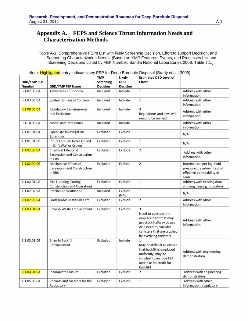
Research, Development, and Demonstration Roadmap for Deep Borehole Disposal August 31, 2012 A-1
Appendix A. FEPS and Science Thrust Information Needs and
Characterization Methods
Table A-1. Comprehensive FEPs List with likely Screening Decision, Effort to support Decision, and
Supporting Characterization Needs. (Based on YMP Features, Events, and Processes List and Screening Decisions Listed by FEP Number: Sandia National Laboratories 2008, Table 7.1.).
Note: Highlighted entry indicates key FEP for Deep Borehole Disposal (Brady et al., 2009)
DBD/YMP FEP Number DBD/YMP FEP Name
YMP Screening Decision
Likely DBD Decision
Estimated DBD Level of Effort
0.1.02.00.0A Timescales of Concern Included Include 1 Address with other information
0.1.03.00.0A Spatial Domain of Concern Included Include 1 Address with other information
0.1.09.00.0A Regulatory Requirements and Exclusions
Included Include 3 Regulations and laws will need to be revised
Address with other information
0.1.10.00.0A Model and Data Issues Included Include 1 Address with other information
1.1.01.01.0A Open Site Investigation Boreholes
Excluded Exclude 1 N/A
1.1.01.01.0B Influx Through Holes Drilled in Drift Wall or Crown
Excluded Exclude 1 N/A
1.1.02.00.0A Chemical Effects of Excavation and Construction in EBS
Excluded Exclude 2 Address with other information
1.1.02.00.0B Mechanical Effects of Excavation and Construction in EBS
Excluded Exclude 2 Borehole caliper log, fluid pressure drawdown test of effective permeability of seals
1.1.02.01.0A Site Flooding (During Construction and Operation)
Excluded Exclude 1 Address with existing data and engineering mitigation
1.1.02.02.0A Preclosure Ventilation Included Exclude (NA)
1 N/A
1.1.02.03.0A Undesirable Materials Left Excluded Exclude 2 Address with other information
1.1.03.01.0A Error in Waste Emplacement Excluded Exclude 3 Need to consider the emplacement that may get stuck halfway down. Also need to consider canisters that are crushed by overlying canisters
Address with other information
1.1.03.01.0B Error in Backfill Emplacement
Excluded Include 1 May be difficult to ensure that backfill is emplaced uniformly, may be simplest to include FEP and take no credit for backfill1
Address with engineering demonstration
1.1.04.01.0A Incomplete Closure Excluded Exclude 2 Address with engineering demonstration
1.1.05.00.0A Records and Markers for the Repository
Excluded Exclude) 1 Address with other information regulatory
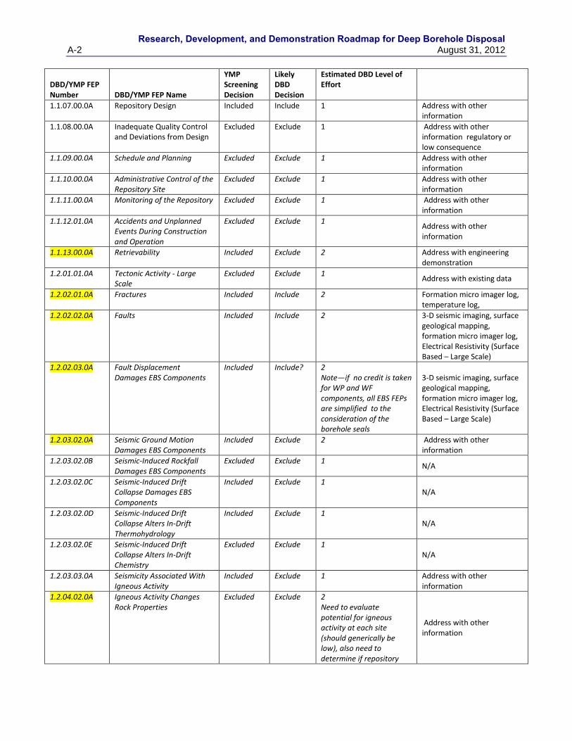
Research, Development, and Demonstration Roadmap for Deep Borehole Disposal
A-2 August 31, 2012
DBD/YMP FEP Number DBD/YMP FEP Name
YMP Screening Decision
Likely DBD Decision
Estimated DBD Level of Effort
1.1.07.00.0A Repository Design Included Include 1 Address with other information
1.1.08.00.0A Inadequate Quality Control and Deviations from Design
Excluded Exclude 1 Address with other information regulatory or low consequence
1.1.09.00.0A Schedule and Planning Excluded Exclude 1 Address with other information
1.1.10.00.0A Administrative Control of the Repository Site
Excluded Exclude 1 Address with other information
1.1.11.00.0A Monitoring of the Repository Excluded Exclude 1 Address with other information
1.1.12.01.0A Accidents and Unplanned Events During Construction and Operation
Excluded Exclude 1 Address with other information
1.1.13.00.0A Retrievability Included Exclude 2 Address with engineering demonstration
1.2.01.01.0A Tectonic Activity - Large Scale
Excluded Exclude 1 Address with existing data
1.2.02.01.0A Fractures Included Include 2 Formation micro imager log, temperature log,
1.2.02.02.0A Faults Included Include 2 3-D seismic imaging, surface geological mapping, formation micro imager log, Electrical Resistivity (Surface Based – Large Scale)
1.2.02.03.0A Fault Displacement Damages EBS Components
Included Include? 2 Note—if no credit is taken for WP and WF components, all EBS FEPs are simplified to the consideration of the borehole seals
3-D seismic imaging, surface geological mapping, formation micro imager log, Electrical Resistivity (Surface Based – Large Scale)
1.2.03.02.0A Seismic Ground Motion Damages EBS Components
Included Exclude 2 Address with other information
1.2.03.02.0B Seismic-Induced Rockfall Damages EBS Components
Excluded Exclude 1 N/A
1.2.03.02.0C Seismic-Induced Drift Collapse Damages EBS Components
Included Exclude 1 N/A
1.2.03.02.0D Seismic-Induced Drift Collapse Alters In-Drift Thermohydrology
Included Exclude 1 N/A
1.2.03.02.0E Seismic-Induced Drift Collapse Alters In-Drift Chemistry
Excluded Exclude 1 N/A
1.2.03.03.0A Seismicity Associated With Igneous Activity
Included Exclude 1 Address with other information
1.2.04.02.0A Igneous Activity Changes Rock Properties
Excluded Exclude 2 Need to evaluate potential for igneous activity at each site (should generically be low), also need to determine if repository
Address with other information
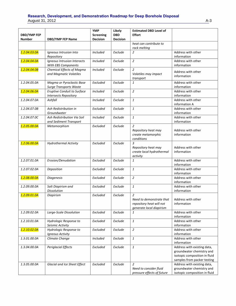
Research, Development, and Demonstration Roadmap for Deep Borehole Disposal August 31, 2012 A-3
DBD/YMP FEP Number DBD/YMP FEP Name
YMP Screening Decision
Likely DBD Decision
Estimated DBD Level of Effort
heat can contribute to rock melting
1.2.04.03.0A Igneous Intrusion Into Repository
Included Exclude 2 Address with other information
1.2.04.04.0A Igneous Intrusion Interacts With EBS Components
Included Exclude 2 Address with other information
1.2.04.04.0B Chemical Effects of Magma and Magmatic Volatiles
Included Exclude 2 Volatiles may impact transport
Address with other information
1.2.04.05.0A Magma or Pyroclastic Base Surge Transports Waste
Excluded Exclude 1 Address with other information
1.2.04.06.0A Eruptive Conduit to Surface Intersects Repository
Included Exclude 2 Address with other information
1.2.04.07.0A Ashfall Included Exclude 1 Address with other information A
1.2.04.07.0B Ash Redistribution in Groundwater
Excluded Exclude 1 Address with other information
1.2.04.07.0C Ash Redistribution Via Soil and Sediment Transport
Included Exclude 1 Address with other information
1.2.05.00.0A Metamorphism Excluded Exclude 2 Repository heat may create metamorphic conditions
Address with other information
1.2.06.00.0A Hydrothermal Activity Excluded Exclude 3 Repository heat may create local hydrothermal activity
Address with other information
1.2.07.01.0A Erosion/Denudation Excluded Exclude 1 Address with other information
1.2.07.02.0A Deposition Excluded Exclude 1 Address with other information
1.2.08.00.0A Diagenesis Excluded Exclude 2 Address with other information
1.2.09.00.0A Salt Diapirism and Dissolution
Excluded Exclude 1 Address with other information
1.2.09.01.0A Diapirism Excluded Exclude 2 Need to demonstrate that repository heat will not generate local diapirism
Address with other information
1.2.09.02.0A Large-Scale Dissolution Excluded Exclude 1 Address with other information
1.2.10.01.0A Hydrologic Response to Seismic Activity
Excluded Exclude 1 Address with other information
1.2.10.02.0A Hydrologic Response to Igneous Activity
Excluded Exclude 2 Address with other information
1.3.01.00.0A Climate Change Included Exclude 1 Address with other information
1.3.04.00.0A Periglacial Effects Excluded Exclude 1 Address with existing data, groundwater chemistry and isotopic composition in fluid samples from packer testing
1.3.05.00.0A Glacial and Ice Sheet Effect Excluded Exclude 2 Need to consider fluid pressure effects of future
Address with existing data, groundwater chemistry and isotopic composition in fluid
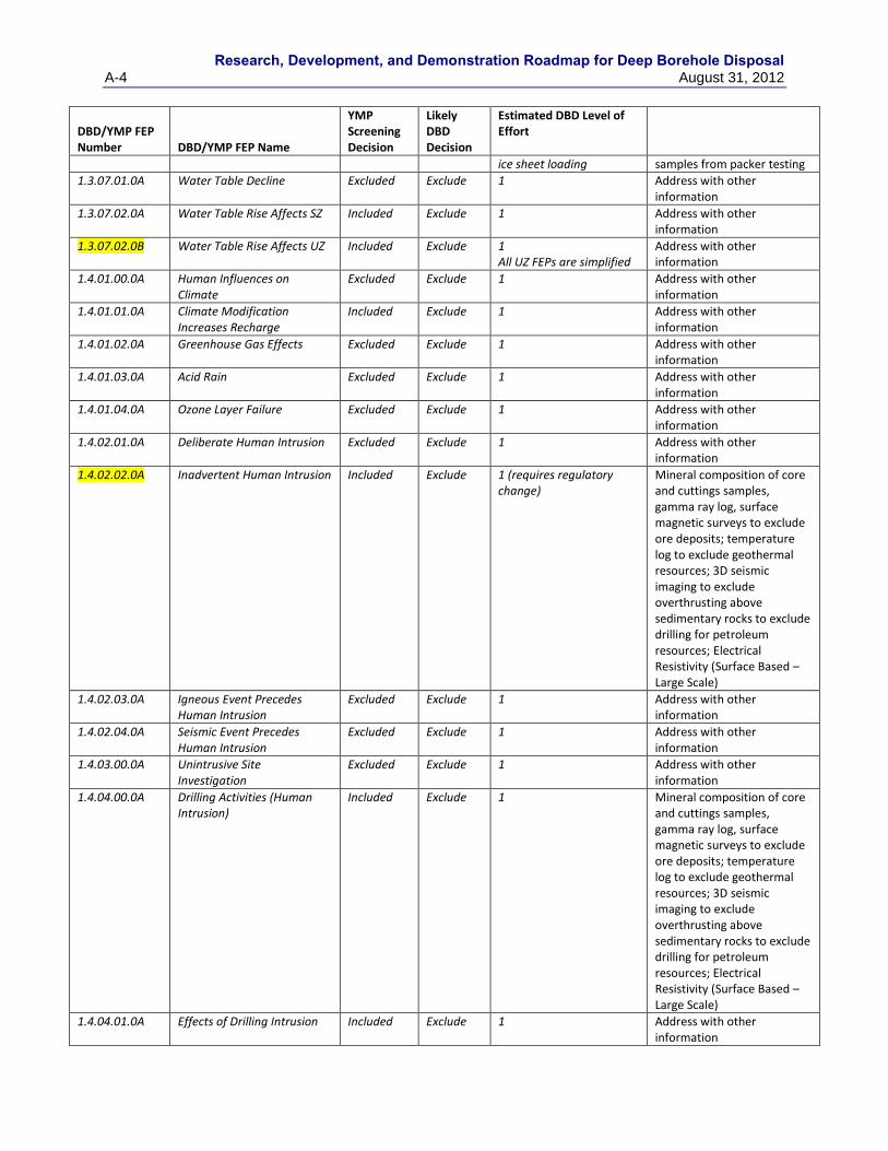
Research, Development, and Demonstration Roadmap for Deep Borehole Disposal
A-4 August 31, 2012
DBD/YMP FEP Number DBD/YMP FEP Name
YMP Screening Decision
Likely DBD Decision
Estimated DBD Level of Effort
ice sheet loading samples from packer testing
1.3.07.01.0A Water Table Decline Excluded Exclude 1 Address with other information
1.3.07.02.0A Water Table Rise Affects SZ Included Exclude 1 Address with other information
1.3.07.02.0B Water Table Rise Affects UZ Included Exclude 1 All UZ FEPs are simplified
Address with other information
1.4.01.00.0A Human Influences on Climate
Excluded Exclude 1 Address with other information
1.4.01.01.0A Climate Modification Increases Recharge
Included Exclude 1 Address with other information
1.4.01.02.0A Greenhouse Gas Effects Excluded Exclude 1 Address with other information
1.4.01.03.0A Acid Rain Excluded Exclude 1 Address with other information
1.4.01.04.0A Ozone Layer Failure Excluded Exclude 1 Address with other information
1.4.02.01.0A Deliberate Human Intrusion Excluded Exclude 1 Address with other information
1.4.02.02.0A Inadvertent Human Intrusion Included Exclude 1 (requires regulatory change)
Mineral composition of core and cuttings samples, gamma ray log, surface magnetic surveys to exclude ore deposits; temperature log to exclude geothermal resources; 3D seismic imaging to exclude overthrusting above sedimentary rocks to exclude drilling for petroleum resources; Electrical Resistivity (Surface Based – Large Scale)
1.4.02.03.0A Igneous Event Precedes Human Intrusion
Excluded Exclude 1 Address with other information
1.4.02.04.0A Seismic Event Precedes Human Intrusion
Excluded Exclude 1 Address with other information
1.4.03.00.0A Unintrusive Site Investigation
Excluded Exclude 1 Address with other information
1.4.04.00.0A Drilling Activities (Human Intrusion)
Included Exclude 1 Mineral composition of core and cuttings samples, gamma ray log, surface magnetic surveys to exclude ore deposits; temperature log to exclude geothermal resources; 3D seismic imaging to exclude overthrusting above sedimentary rocks to exclude drilling for petroleum resources; Electrical Resistivity (Surface Based – Large Scale)
1.4.04.01.0A Effects of Drilling Intrusion Included Exclude 1 Address with other information
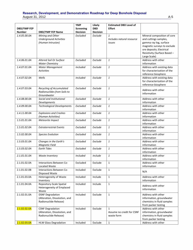
Research, Development, and Demonstration Roadmap for Deep Borehole Disposal August 31, 2012 A-5
DBD/YMP FEP Number DBD/YMP FEP Name
YMP Screening Decision
Likely DBD Decision
Estimated DBD Level of Effort
1.4.05.00.0A Mining and Other Underground Activities (Human Intrusion)
Excluded Exclude 1 Includes natural resource issues
Mineral composition of core and cuttings samples, gamma ray log, surface magnetic surveys to exclude ore deposits; Electrical Resistivity (Surface Based – Large Scale)
1.4.06.01.0A Altered Soil Or Surface Water Chemistry
Excluded Exclude 1 Address with other information
1.4.07.01.0A Water Management Activities
Included Exclude 1 Address with existing data for characterization of the reference biosphere
1.4.07.02.0A Wells Included Exclude 1 Address with existing data for characterization of the reference biosphere
1.4.07.03.0A Recycling of Accumulated Radionuclides from Soils to Groundwater
Excluded Exclude 1 Address with other information
1.4.08.00.0A Social and Institutional Developments
Excluded Exclude 1 Address with other information
1.4.09.00.0A Technological Developments Excluded Exclude 1 Address with other information
1.4.11.00.0A Explosions and Crashes (Human Activities)
Excluded Exclude 1 Address with other information
1.5.01.01.0A Meteorite Impact Excluded Exclude 1 Address with other information
1.5.01.02.0A Extraterrestrial Events Excluded Exclude 1 Address with other information
1.5.02.00.0A Species Evolution Excluded Exclude 1 Address with other information
1.5.03.01.0A Changes in the Earth's Magnetic Field
Excluded Exclude 1 Address with other information
1.5.03.02.0A Earth Tides Excluded Exclude 1 Address with other information
2.1.01.01.0A Waste Inventory Included Include 1 Address with other information
2.1.01.02.0A Interactions Between Co-Located Waste
Excluded Exclude 1 Address with other information
2.1.01.02.0B Interactions Between Co-Disposed Waste
Included Exclude 1 N/A
2.1.01.03.0A Heterogeneity of Waste Inventory
Included Include 1 Address with other information
2.1.01.04.0A Repository-Scale Spatial Heterogeneity of Emplaced Waste
Included Include 1 Address with other information
2.1.02.01.0A DSNF Degradation (Alteration, Dissolution, and Radionuclide Release)
Included Exclude 1 Address with other information, groundwater chemistry in fluid samples from packer testing
2.1.02.02.0A CSNF Degradation (Alteration, Dissolution, and Radionuclide Release)
Included Exclude 1 Assume no credit for CSNF waste form
Address with other information, groundwater chemistry in fluid samples from packer testing
2.1.02.03.0A HLW Glass Degradation Included Exclude 1 Address with other
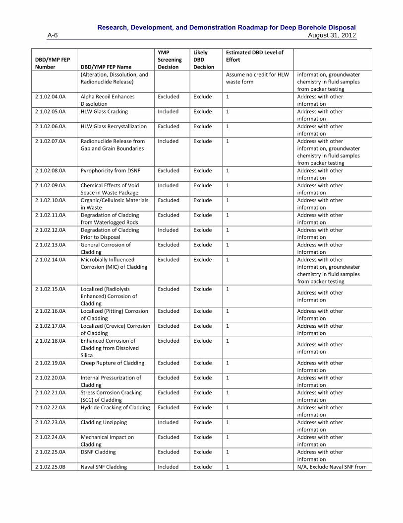
Research, Development, and Demonstration Roadmap for Deep Borehole Disposal
A-6 August 31, 2012
DBD/YMP FEP Number DBD/YMP FEP Name
YMP Screening Decision
Likely DBD Decision
Estimated DBD Level of Effort
(Alteration, Dissolution, and Radionuclide Release)
Assume no credit for HLW waste form
information, groundwater chemistry in fluid samples from packer testing
2.1.02.04.0A Alpha Recoil Enhances Dissolution
Excluded Exclude 1 Address with other information
2.1.02.05.0A HLW Glass Cracking Included Exclude 1 Address with other information
2.1.02.06.0A HLW Glass Recrystallization Excluded Exclude 1 Address with other information
2.1.02.07.0A Radionuclide Release from Gap and Grain Boundaries
Included Exclude 1 Address with other information, groundwater chemistry in fluid samples from packer testing
2.1.02.08.0A Pyrophoricity from DSNF Excluded Exclude 1 Address with other information
2.1.02.09.0A Chemical Effects of Void Space in Waste Package
Included Exclude 1 Address with other information
2.1.02.10.0A Organic/Cellulosic Materials in Waste
Excluded Exclude 1 Address with other information
2.1.02.11.0A Degradation of Cladding from Waterlogged Rods
Excluded Exclude 1 Address with other information
2.1.02.12.0A Degradation of Cladding Prior to Disposal
Included Exclude 1 Address with other information
2.1.02.13.0A General Corrosion of Cladding
Excluded Exclude 1 Address with other information
2.1.02.14.0A Microbially Influenced Corrosion (MIC) of Cladding
Excluded Exclude 1 Address with other information, groundwater chemistry in fluid samples from packer testing
2.1.02.15.0A Localized (Radiolysis Enhanced) Corrosion of Cladding
Excluded Exclude 1 Address with other information
2.1.02.16.0A Localized (Pitting) Corrosion of Cladding
Excluded Exclude 1 Address with other information
2.1.02.17.0A Localized (Crevice) Corrosion of Cladding
Excluded Exclude 1 Address with other information
2.1.02.18.0A Enhanced Corrosion of Cladding from Dissolved Silica
Excluded Exclude 1 Address with other information
2.1.02.19.0A Creep Rupture of Cladding Excluded Exclude 1 Address with other information
2.1.02.20.0A Internal Pressurization of Cladding
Excluded Exclude 1 Address with other information
2.1.02.21.0A Stress Corrosion Cracking (SCC) of Cladding
Excluded Exclude 1 Address with other information
2.1.02.22.0A Hydride Cracking of Cladding Excluded Exclude 1 Address with other information
2.1.02.23.0A Cladding Unzipping Included Exclude 1 Address with other information
2.1.02.24.0A Mechanical Impact on Cladding
Excluded Exclude 1 Address with other information
2.1.02.25.0A DSNF Cladding Excluded Exclude 1 Address with other information
2.1.02.25.0B Naval SNF Cladding Included Exclude 1 N/A, Exclude Naval SNF from
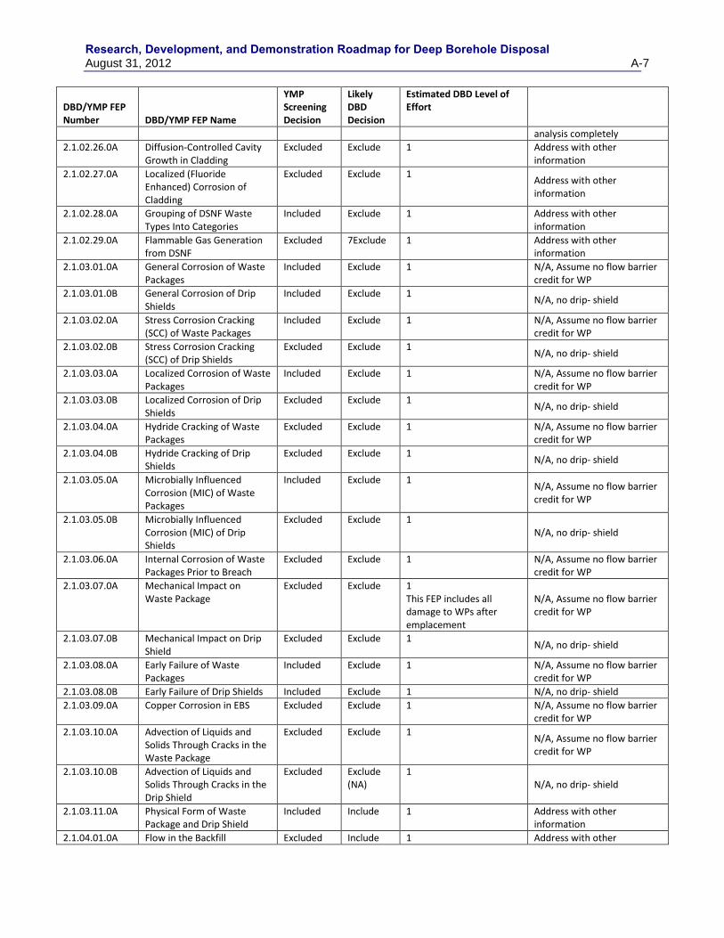
Research, Development, and Demonstration Roadmap for Deep Borehole Disposal August 31, 2012 A-7
DBD/YMP FEP Number DBD/YMP FEP Name
YMP Screening Decision
Likely DBD Decision
Estimated DBD Level of Effort
analysis completely
2.1.02.26.0A Diffusion-Controlled Cavity Growth in Cladding
Excluded Exclude 1 Address with other information
2.1.02.27.0A Localized (Fluoride Enhanced) Corrosion of Cladding
Excluded Exclude 1 Address with other information
2.1.02.28.0A Grouping of DSNF Waste Types Into Categories
Included Exclude 1 Address with other information
2.1.02.29.0A Flammable Gas Generation from DSNF
Excluded 7Exclude 1 Address with other information
2.1.03.01.0A General Corrosion of Waste Packages
Included Exclude 1
N/A, Assume no flow barrier credit for WP
2.1.03.01.0B General Corrosion of Drip Shields
Included Exclude 1 N/A, no drip- shield
2.1.03.02.0A Stress Corrosion Cracking (SCC) of Waste Packages
Included Exclude 1 N/A, Assume no flow barrier credit for WP
2.1.03.02.0B Stress Corrosion Cracking (SCC) of Drip Shields
Excluded Exclude 1 N/A, no drip- shield
2.1.03.03.0A Localized Corrosion of Waste Packages
Included Exclude 1 N/A, Assume no flow barrier credit for WP
2.1.03.03.0B Localized Corrosion of Drip Shields
Excluded Exclude 1 N/A, no drip- shield
2.1.03.04.0A Hydride Cracking of Waste Packages
Excluded Exclude 1 N/A, Assume no flow barrier credit for WP
2.1.03.04.0B Hydride Cracking of Drip Shields
Excluded Exclude 1 N/A, no drip- shield
2.1.03.05.0A Microbially Influenced Corrosion (MIC) of Waste Packages
Included Exclude 1 N/A, Assume no flow barrier credit for WP
2.1.03.05.0B Microbially Influenced Corrosion (MIC) of Drip Shields
Excluded Exclude 1 N/A, no drip- shield
2.1.03.06.0A Internal Corrosion of Waste Packages Prior to Breach
Excluded Exclude 1 N/A, Assume no flow barrier credit for WP
2.1.03.07.0A Mechanical Impact on Waste Package
Excluded Exclude 1 This FEP includes all damage to WPs after emplacement
N/A, Assume no flow barrier credit for WP
2.1.03.07.0B Mechanical Impact on Drip Shield
Excluded Exclude 1 N/A, no drip- shield
2.1.03.08.0A Early Failure of Waste Packages
Included Exclude 1 N/A, Assume no flow barrier credit for WP
2.1.03.08.0B Early Failure of Drip Shields Included Exclude 1 N/A, no drip- shield
2.1.03.09.0A Copper Corrosion in EBS Excluded Exclude 1 N/A, Assume no flow barrier credit for WP
2.1.03.10.0A Advection of Liquids and Solids Through Cracks in the Waste Package
Excluded Exclude 1 N/A, Assume no flow barrier credit for WP
2.1.03.10.0B Advection of Liquids and Solids Through Cracks in the Drip Shield
Excluded Exclude (NA)
1 N/A, no drip- shield
2.1.03.11.0A Physical Form of Waste Package and Drip Shield
Included Include 1 Address with other information
2.1.04.01.0A Flow in the Backfill Excluded Include 1 Address with other
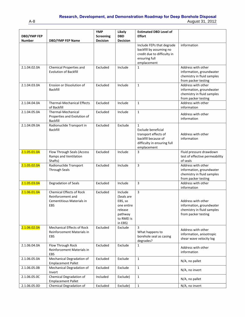
Research, Development, and Demonstration Roadmap for Deep Borehole Disposal
A-8 August 31, 2012
DBD/YMP FEP Number DBD/YMP FEP Name
YMP Screening Decision
Likely DBD Decision
Estimated DBD Level of Effort
Include FEPs that degrade backfill by assuming no credit due to difficulty in ensuring full emplacement
information
2.1.04.02.0A Chemical Properties and Evolution of Backfill
Excluded Include 1 Address with other information, groundwater chemistry in fluid samples from packer testing
2.1.04.03.0A Erosion or Dissolution of Backfill
Excluded Include 1 Address with other information, groundwater chemistry in fluid samples from packer testing
2.1.04.04.0A Thermal-Mechanical Effects of Backfill
Excluded Include 1 Address with other information
2.1.04.05.0A Thermal-Mechanical Properties and Evolution of Backfill
Excluded Include 1 Address with other information
2.1.04.09.0A Radionuclide Transport in Backfill
Excluded Exclude 1 Exclude beneficial transport effects of backfill because of difficulty in ensuring full emplacement
Address with other information
2.1.05.01.0A Flow Through Seals (Access Ramps and Ventilation Shafts)
Excluded Include 3 Fluid pressure drawdown test of effective permeability of seals
2.1.05.02.0A Radionuclide Transport Through Seals
Excluded Include 3 Address with other information, groundwater chemistry in fluid samples from packer testing
2.1.05.03.0A Degradation of Seals Excluded Include 3 Address with other information
2.1.06.01.0A Chemical Effects of Rock Reinforcement and Cementitious Materials in EBS
Excluded Include (Seals are EBS, so one entire release pathway to RMEI is in EBS)
3
Address with other information, groundwater chemistry in fluid samples from packer testing
2.1.06.02.0A Mechanical Effects of Rock Reinforcement Materials in EBS
Excluded Exclude 3 What happens to borehole seal as casing degrades?
Address with other information, anisotropic shear wave velocity log
2.1.06.04.0A Flow Through Rock Reinforcement Materials in EBS
Excluded Exclude 1 Address with other information
2.1.06.05.0A Mechanical Degradation of Emplacement Pallet
Excluded Exclude 1 N/A, no pallet
2.1.06.05.0B Mechanical Degradation of Invert
Excluded Exclude 1 N/A, no invert
2.1.06.05.0C Chemical Degradation of Emplacement Pallet
Included Exclude) 1 N/A, no pallet
2.1.06.05.0D Chemical Degradation of Excluded Exclude) 1 N/A, no invert
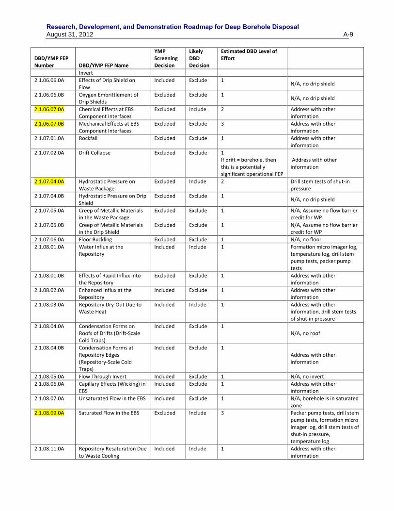
Research, Development, and Demonstration Roadmap for Deep Borehole Disposal August 31, 2012 A-9
DBD/YMP FEP Number DBD/YMP FEP Name
YMP Screening Decision
Likely DBD Decision
Estimated DBD Level of Effort
Invert
2.1.06.06.0A Effects of Drip Shield on Flow
Included Exclude 1 N/A, no drip shield
2.1.06.06.0B Oxygen Embrittlement of Drip Shields
Excluded Exclude 1 N/A, no drip shield
2.1.06.07.0A Chemical Effects at EBS Component Interfaces
Excluded Include 2 Address with other information
2.1.06.07.0B Mechanical Effects at EBS Component Interfaces
Excluded Exclude 3 Address with other information
2.1.07.01.0A Rockfall Excluded Exclude 1 Address with other information
2.1.07.02.0A Drift Collapse Excluded Exclude 1 If drift = borehole, then this is a potentially significant operational FEP
Address with other information
2.1.07.04.0A Hydrostatic Pressure on Waste Package
Excluded Include 2 Drill stem tests of shut-in pressure
2.1.07.04.0B Hydrostatic Pressure on Drip Shield
Excluded Exclude 1 N/A, no drip shield
2.1.07.05.0A Creep of Metallic Materials in the Waste Package
Excluded Exclude 1 N/A, Assume no flow barrier credit for WP
2.1.07.05.0B Creep of Metallic Materials in the Drip Shield
Excluded Exclude 1 N/A, Assume no flow barrier credit for WP
2.1.07.06.0A Floor Buckling Excluded Exclude 1 N/A, no floor
2.1.08.01.0A Water Influx at the Repository
Included Include 1 Formation micro imager log, temperature log, drill stem pump tests, packer pump tests
2.1.08.01.0B Effects of Rapid Influx into the Repository
Excluded Exclude 1 Address with other information
2.1.08.02.0A Enhanced Influx at the Repository
Included Exclude 1 Address with other information
2.1.08.03.0A Repository Dry-Out Due to Waste Heat
Included Include 1 Address with other information, drill stem tests of shut-in pressure
2.1.08.04.0A Condensation Forms on Roofs of Drifts (Drift-Scale Cold Traps)
Included Exclude 1 N/A, no roof
2.1.08.04.0B Condensation Forms at Repository Edges (Repository-Scale Cold Traps)
Included Exclude 1 Address with other information
2.1.08.05.0A Flow Through Invert Included Exclude 1 N/A, no invert
2.1.08.06.0A Capillary Effects (Wicking) in EBS
Included Exclude 1 Address with other information
2.1.08.07.0A Unsaturated Flow in the EBS Included Exclude 1 N/A, borehole is in saturated zone
2.1.08.09.0A Saturated Flow in the EBS Excluded Include 3 Packer pump tests, drill stem pump tests, formation micro imager log, drill stem tests of shut-in pressure, temperature log
2.1.08.11.0A Repository Resaturation Due to Waste Cooling
Included Include 1 Address with other information
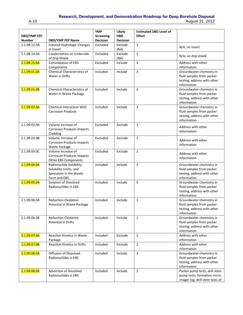
Research, Development, and Demonstration Roadmap for Deep Borehole Disposal
A-10 August 31, 2012
DBD/YMP FEP Number DBD/YMP FEP Name
YMP Screening Decision
Likely DBD Decision
Estimated DBD Level of Effort
2.1.08.12.0A Induced Hydrologic Changes in Invert
Excluded Exclude (NA)
1 N/A, no invert
2.1.08.14.0A Condensation on Underside of Drip Shield
Excluded Exclude (NA)
1 N/A, no drip shield
2.1.08.15.0A Consolidation of EBS Components
Excluded Include 3 Address with other information
2.1.09.01.0A Chemical Characteristics of Water in Drifts
Included Include 3 Groundwater chemistry in fluid samples from packer testing, address with other information
2.1.09.01.0B Chemical Characteristics of Water in Waste Package
Included Include 3 Groundwater chemistry in fluid samples from packer testing, address with other information
2.1.09.02.0A Chemical Interaction With Corrosion Products
Included Include 3 Groundwater chemistry in fluid samples from packer testing, address with other information
2.1.09.03.0A Volume Increase of Corrosion Products Impacts Cladding
Excluded Exclude 1 Address with other information
2.1.09.03.0B Volume Increase of Corrosion Products Impacts Waste Package
Excluded Exclude 1 Address with other information
2.1.09.03.0C Volume Increase of Corrosion Products Impacts Other EBS Components
Excluded Exclude 1 Address with other information
2.1.09.04.0A Radionuclide Solubility, Solubility Limits, and Speciation in the Waste Form and EBS
Included Include 3 Groundwater chemistry in fluid samples from packer testing, address with other information
2.1.09.05.0A Sorption of Dissolved Radionuclides in EBS
Included Include 3 Groundwater chemistry in fluid samples from packer testing, address with other information
2.1.09.06.0A Reduction-Oxidation Potential in Waste Package
Included Include 1 Groundwater chemistry in fluid samples from packer testing, address with other information
2.1.09.06.0B Reduction-Oxidation Potential in Drifts
Included Include 1 Groundwater chemistry in fluid samples from packer testing, address with other information
2.1.09.07.0A Reaction Kinetics in Waste Package
Included Exclude 2 Address with other information
2.1.09.07.0B Reaction Kinetics in Drifts Included Exclude 2 Address with other information
2.1.09.08.0A Diffusion of Dissolved Radionuclides in EBS
Included Include 3 Groundwater chemistry in fluid samples from packer testing, address with other information
2.1.09.08.0B Advection of Dissolved Radionuclides in EBS
Included Include 3 Packer pump tests, drill stem pump tests, formation micro imager log, drill stem tests of
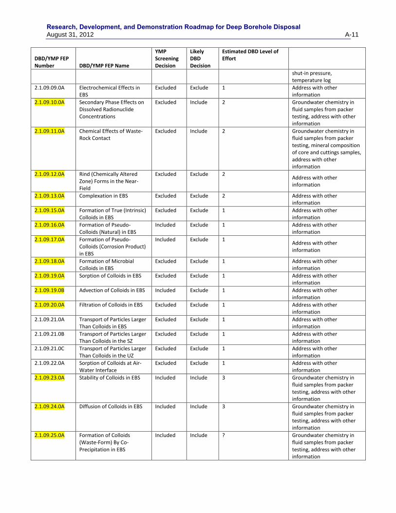
Research, Development, and Demonstration Roadmap for Deep Borehole Disposal August 31, 2012 A-11
DBD/YMP FEP Number DBD/YMP FEP Name
YMP Screening Decision
Likely DBD Decision
Estimated DBD Level of Effort
shut-in pressure, temperature log
2.1.09.09.0A Electrochemical Effects in EBS
Excluded Exclude 1 Address with other information
2.1.09.10.0A Secondary Phase Effects on Dissolved Radionuclide Concentrations
Excluded Include 2 Groundwater chemistry in fluid samples from packer testing, address with other information
2.1.09.11.0A Chemical Effects of Waste-Rock Contact
Excluded Include 2 Groundwater chemistry in fluid samples from packer testing, mineral composition of core and cuttings samples, address with other information
2.1.09.12.0A Rind (Chemically Altered Zone) Forms in the Near-Field
Excluded Exclude 2 Address with other information
2.1.09.13.0A Complexation in EBS Excluded Exclude 2 Address with other information
2.1.09.15.0A Formation of True (Intrinsic) Colloids in EBS
Excluded Exclude 1 Address with other information
2.1.09.16.0A Formation of Pseudo-Colloids (Natural) in EBS
Included Exclude 1 Address with other information
2.1.09.17.0A Formation of Pseudo-Colloids (Corrosion Product) in EBS
Included Exclude 1 Address with other information
2.1.09.18.0A Formation of Microbial Colloids in EBS
Excluded Exclude 1 Address with other information
2.1.09.19.0A Sorption of Colloids in EBS Excluded Exclude 1 Address with other information
2.1.09.19.0B Advection of Colloids in EBS Included Exclude 1 Address with other information
2.1.09.20.0A Filtration of Colloids in EBS Excluded Exclude 1 Address with other information
2.1.09.21.0A Transport of Particles Larger Than Colloids in EBS
Excluded Exclude 1 Address with other information
2.1.09.21.0B Transport of Particles Larger Than Colloids in the SZ
Excluded Exclude 1
Address with other information
2.1.09.21.0C Transport of Particles Larger Than Colloids in the UZ
Excluded Exclude 1 Address with other information
2.1.09.22.0A Sorption of Colloids at Air-Water Interface
Excluded Exclude 1 Address with other information
2.1.09.23.0A Stability of Colloids in EBS Included Include 3 Groundwater chemistry in fluid samples from packer testing, address with other information
2.1.09.24.0A Diffusion of Colloids in EBS Included Include 3 Groundwater chemistry in fluid samples from packer testing, address with other information
2.1.09.25.0A Formation of Colloids (Waste-Form) By Co-Precipitation in EBS
Included Include ? Groundwater chemistry in fluid samples from packer testing, address with other information
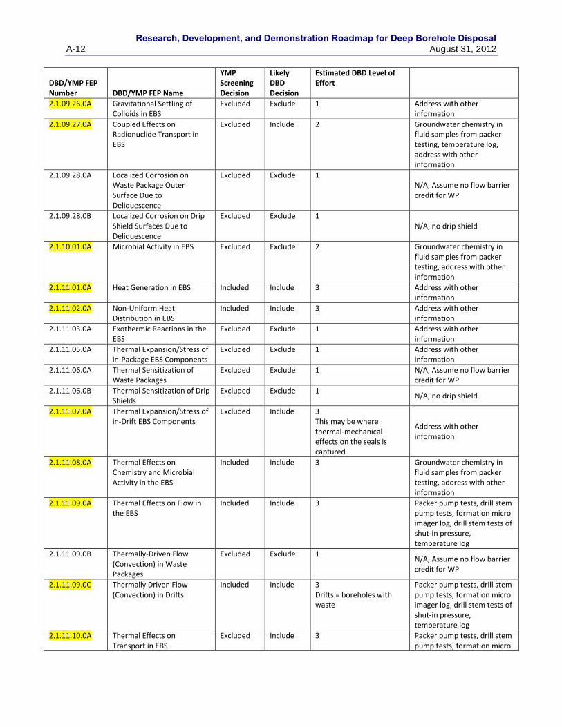
Research, Development, and Demonstration Roadmap for Deep Borehole Disposal
A-12 August 31, 2012
DBD/YMP FEP Number DBD/YMP FEP Name
YMP Screening Decision
Likely DBD Decision
Estimated DBD Level of Effort
2.1.09.26.0A Gravitational Settling of Colloids in EBS
Excluded Exclude 1 Address with other information
2.1.09.27.0A Coupled Effects on Radionuclide Transport in EBS
Excluded Include 2 Groundwater chemistry in fluid samples from packer testing, temperature log, address with other information
2.1.09.28.0A Localized Corrosion on Waste Package Outer Surface Due to Deliquescence
Excluded Exclude 1 N/A, Assume no flow barrier credit for WP
2.1.09.28.0B Localized Corrosion on Drip Shield Surfaces Due to Deliquescence
Excluded Exclude 1 N/A, no drip shield
2.1.10.01.0A Microbial Activity in EBS Excluded Exclude 2 Groundwater chemistry in fluid samples from packer testing, address with other information
2.1.11.01.0A Heat Generation in EBS Included Include 3 Address with other information
2.1.11.02.0A Non-Uniform Heat Distribution in EBS
Included Include 3 Address with other information
2.1.11.03.0A Exothermic Reactions in the EBS
Excluded Exclude 1 Address with other information
2.1.11.05.0A Thermal Expansion/Stress of in-Package EBS Components
Excluded Exclude 1 Address with other information
2.1.11.06.0A Thermal Sensitization of Waste Packages
Excluded Exclude 1 N/A, Assume no flow barrier credit for WP
2.1.11.06.0B Thermal Sensitization of Drip Shields
Excluded Exclude 1 N/A, no drip shield
2.1.11.07.0A Thermal Expansion/Stress of in-Drift EBS Components
Excluded Include 3 This may be where thermal-mechanical effects on the seals is captured
Address with other information
2.1.11.08.0A Thermal Effects on Chemistry and Microbial Activity in the EBS
Included Include 3 Groundwater chemistry in fluid samples from packer testing, address with other information
2.1.11.09.0A Thermal Effects on Flow in the EBS
Included Include 3 Packer pump tests, drill stem pump tests, formation micro imager log, drill stem tests of shut-in pressure, temperature log
2.1.11.09.0B Thermally-Driven Flow (Convection) in Waste Packages
Excluded Exclude 1 N/A, Assume no flow barrier credit for WP
2.1.11.09.0C Thermally Driven Flow (Convection) in Drifts
Included Include 3 Drifts = boreholes with waste
Packer pump tests, drill stem pump tests, formation micro imager log, drill stem tests of shut-in pressure, temperature log
2.1.11.10.0A Thermal Effects on Transport in EBS
Excluded Include 3 Packer pump tests, drill stem pump tests, formation micro
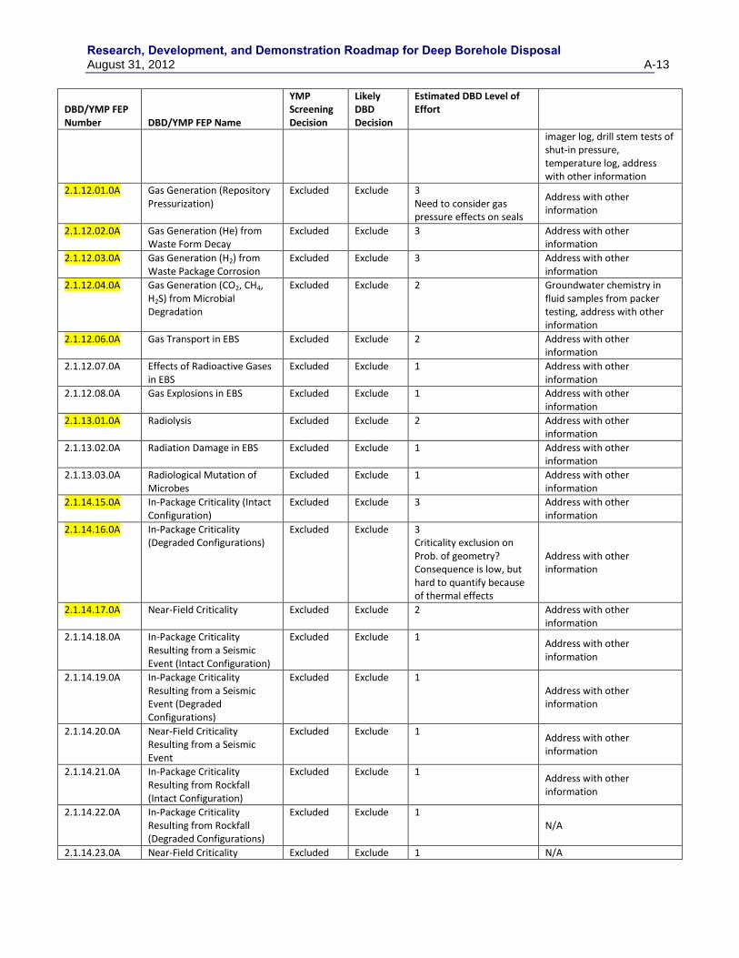
Research, Development, and Demonstration Roadmap for Deep Borehole Disposal August 31, 2012 A-13
DBD/YMP FEP Number DBD/YMP FEP Name
YMP Screening Decision
Likely DBD Decision
Estimated DBD Level of Effort
imager log, drill stem tests of shut-in pressure, temperature log, address with other information
2.1.12.01.0A Gas Generation (Repository Pressurization)
Excluded Exclude 3 Need to consider gas pressure effects on seals
Address with other information
2.1.12.02.0A Gas Generation (He) from Waste Form Decay
Excluded Exclude 3 Address with other information
2.1.12.03.0A Gas Generation (H2) from Waste Package Corrosion
Excluded Exclude 3 Address with other information
2.1.12.04.0A Gas Generation (CO2, CH4, H2S) from Microbial Degradation
Excluded Exclude 2 Groundwater chemistry in fluid samples from packer testing, address with other information
2.1.12.06.0A Gas Transport in EBS Excluded Exclude 2 Address with other information
2.1.12.07.0A Effects of Radioactive Gases in EBS
Excluded Exclude 1 Address with other information
2.1.12.08.0A Gas Explosions in EBS Excluded Exclude 1 Address with other information
2.1.13.01.0A Radiolysis Excluded Exclude 2 Address with other information
2.1.13.02.0A Radiation Damage in EBS Excluded Exclude 1 Address with other information
2.1.13.03.0A Radiological Mutation of Microbes
Excluded Exclude 1 Address with other information
2.1.14.15.0A In-Package Criticality (Intact Configuration)
Excluded Exclude 3 Address with other information
2.1.14.16.0A In-Package Criticality (Degraded Configurations)
Excluded Exclude 3 Criticality exclusion on Prob. of geometry? Consequence is low, but hard to quantify because of thermal effects
Address with other information
2.1.14.17.0A Near-Field Criticality Excluded Exclude 2 Address with other information
2.1.14.18.0A In-Package Criticality Resulting from a Seismic Event (Intact Configuration)
Excluded Exclude 1 Address with other information
2.1.14.19.0A In-Package Criticality Resulting from a Seismic Event (Degraded Configurations)
Excluded Exclude 1 Address with other information
2.1.14.20.0A Near-Field Criticality Resulting from a Seismic Event
Excluded Exclude 1 Address with other information
2.1.14.21.0A In-Package Criticality Resulting from Rockfall (Intact Configuration)
Excluded Exclude 1 Address with other information
2.1.14.22.0A In-Package Criticality Resulting from Rockfall (Degraded Configurations)
Excluded Exclude 1 N/A
2.1.14.23.0A Near-Field Criticality Excluded Exclude 1 N/A
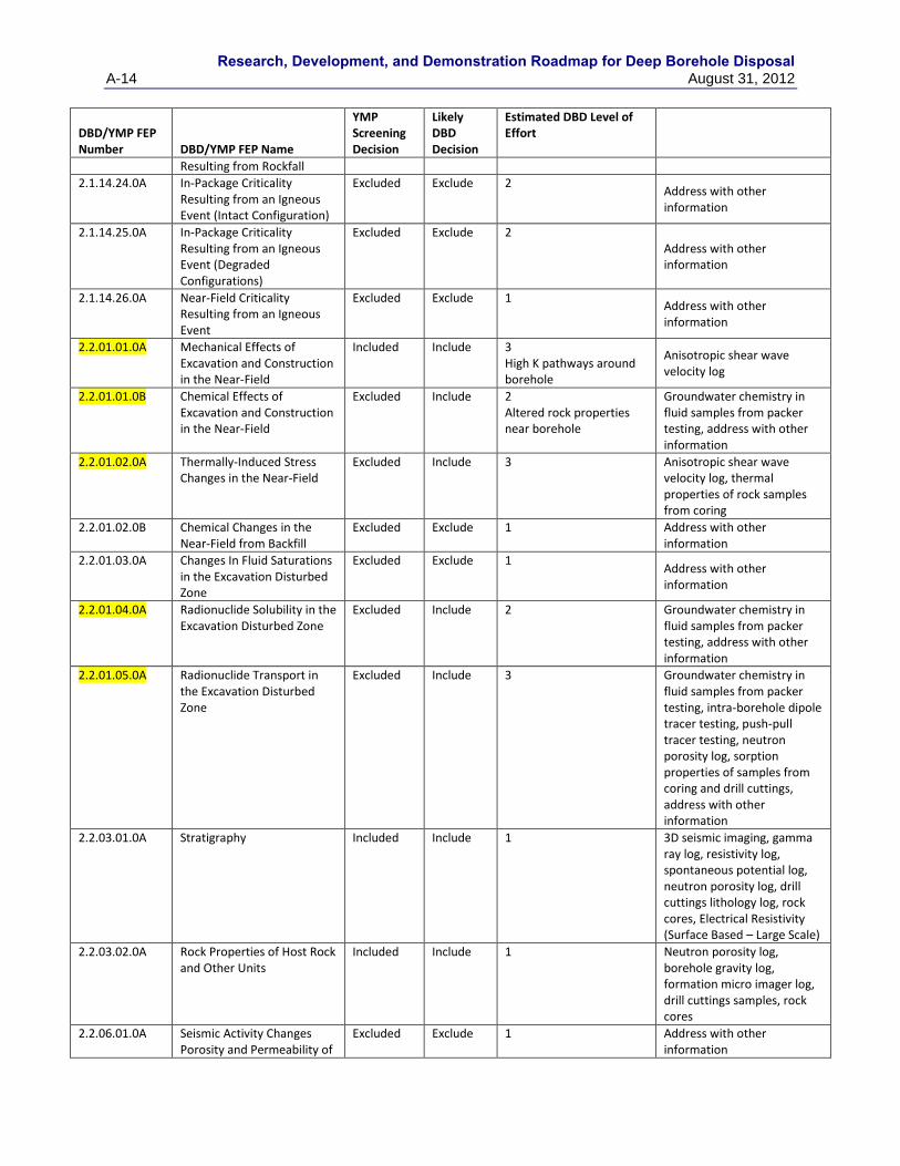
Research, Development, and Demonstration Roadmap for Deep Borehole Disposal
A-14 August 31, 2012
DBD/YMP FEP Number DBD/YMP FEP Name
YMP Screening Decision
Likely DBD Decision
Estimated DBD Level of Effort
Resulting from Rockfall
2.1.14.24.0A In-Package Criticality Resulting from an Igneous Event (Intact Configuration)
Excluded Exclude 2 Address with other information
2.1.14.25.0A In-Package Criticality Resulting from an Igneous Event (Degraded Configurations)
Excluded Exclude 2 Address with other information
2.1.14.26.0A Near-Field Criticality Resulting from an Igneous Event
Excluded Exclude 1 Address with other information
2.2.01.01.0A Mechanical Effects of Excavation and Construction in the Near-Field
Included Include 3 High K pathways around borehole
Anisotropic shear wave velocity log
2.2.01.01.0B Chemical Effects of Excavation and Construction in the Near-Field
Excluded Include 2 Altered rock properties near borehole
Groundwater chemistry in fluid samples from packer testing, address with other information
2.2.01.02.0A Thermally-Induced Stress Changes in the Near-Field
Excluded Include 3 Anisotropic shear wave velocity log, thermal properties of rock samples from coring
2.2.01.02.0B Chemical Changes in the Near-Field from Backfill
Excluded Exclude 1 Address with other information
2.2.01.03.0A Changes In Fluid Saturations in the Excavation Disturbed Zone
Excluded Exclude 1 Address with other information
2.2.01.04.0A Radionuclide Solubility in the Excavation Disturbed Zone
Excluded Include 2 Groundwater chemistry in fluid samples from packer testing, address with other information
2.2.01.05.0A Radionuclide Transport in the Excavation Disturbed Zone
Excluded Include 3 Groundwater chemistry in fluid samples from packer testing, intra-borehole dipole tracer testing, push-pull tracer testing, neutron porosity log, sorption properties of samples from coring and drill cuttings, address with other information
2.2.03.01.0A Stratigraphy Included Include 1 3D seismic imaging, gamma ray log, resistivity log, spontaneous potential log, neutron porosity log, drill cuttings lithology log, rock cores, Electrical Resistivity (Surface Based – Large Scale)
2.2.03.02.0A Rock Properties of Host Rock and Other Units
Included Include 1 Neutron porosity log, borehole gravity log, formation micro imager log, drill cuttings samples, rock cores
2.2.06.01.0A Seismic Activity Changes Porosity and Permeability of
Excluded Exclude 1 Address with other information
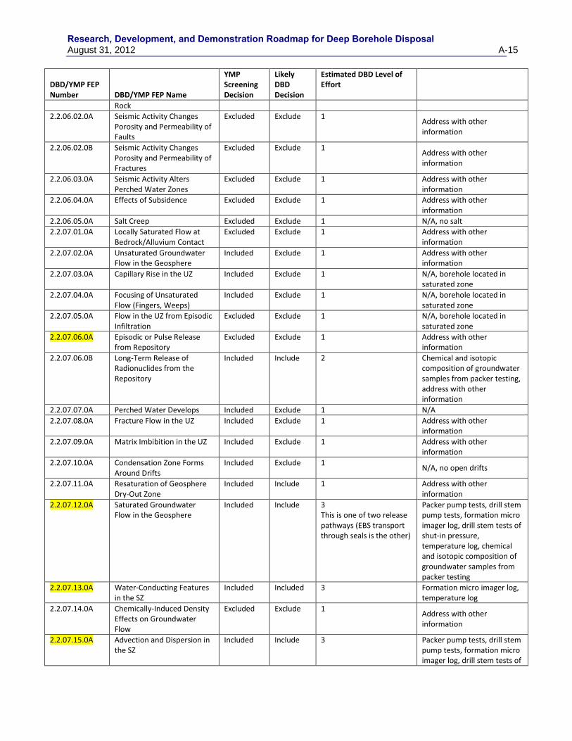
Research, Development, and Demonstration Roadmap for Deep Borehole Disposal August 31, 2012 A-15
DBD/YMP FEP Number DBD/YMP FEP Name
YMP Screening Decision
Likely DBD Decision
Estimated DBD Level of Effort
Rock
2.2.06.02.0A Seismic Activity Changes Porosity and Permeability of Faults
Excluded Exclude 1 Address with other information
2.2.06.02.0B Seismic Activity Changes Porosity and Permeability of Fractures
Excluded Exclude 1 Address with other information
2.2.06.03.0A Seismic Activity Alters Perched Water Zones
Excluded Exclude 1 Address with other information
2.2.06.04.0A Effects of Subsidence Excluded Exclude 1 Address with other information
2.2.06.05.0A Salt Creep Excluded Exclude 1 N/A, no salt
2.2.07.01.0A Locally Saturated Flow at Bedrock/Alluvium Contact
Excluded Exclude 1 Address with other information
2.2.07.02.0A Unsaturated Groundwater Flow in the Geosphere
Included Exclude 1 Address with other information
2.2.07.03.0A Capillary Rise in the UZ Included Exclude 1 N/A, borehole located in saturated zone
2.2.07.04.0A Focusing of Unsaturated Flow (Fingers, Weeps)
Included Exclude 1 N/A, borehole located in saturated zone
2.2.07.05.0A Flow in the UZ from Episodic Infiltration
Excluded Exclude 1 N/A, borehole located in saturated zone
2.2.07.06.0A Episodic or Pulse Release from Repository
Excluded Exclude 1 Address with other information
2.2.07.06.0B Long-Term Release of Radionuclides from the Repository
Included Include 2 Chemical and isotopic composition of groundwater samples from packer testing, address with other information
2.2.07.07.0A Perched Water Develops Included Exclude 1 N/A
2.2.07.08.0A Fracture Flow in the UZ Included Exclude 1 Address with other information
2.2.07.09.0A Matrix Imbibition in the UZ Included Exclude 1 Address with other information
2.2.07.10.0A Condensation Zone Forms Around Drifts
Included Exclude 1 N/A, no open drifts
2.2.07.11.0A Resaturation of Geosphere Dry-Out Zone
Included Include 1 Address with other information
2.2.07.12.0A Saturated Groundwater Flow in the Geosphere
Included Include 3 This is one of two release pathways (EBS transport through seals is the other)
Packer pump tests, drill stem pump tests, formation micro imager log, drill stem tests of shut-in pressure, temperature log, chemical and isotopic composition of groundwater samples from packer testing
2.2.07.13.0A Water-Conducting Features in the SZ
Included Included 3 Formation micro imager log, temperature log
2.2.07.14.0A Chemically-Induced Density Effects on Groundwater Flow
Excluded Exclude 1 Address with other information
2.2.07.15.0A Advection and Dispersion in the SZ
Included Include 3 Packer pump tests, drill stem pump tests, formation micro imager log, drill stem tests of
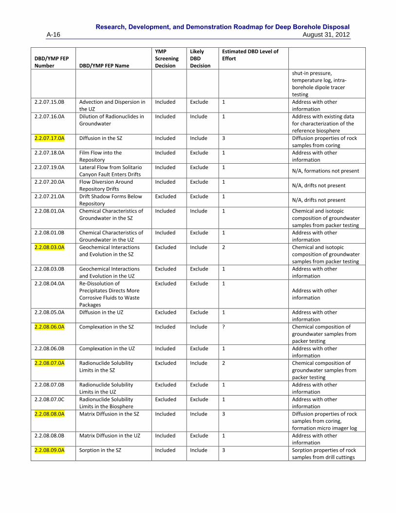
Research, Development, and Demonstration Roadmap for Deep Borehole Disposal
A-16 August 31, 2012
DBD/YMP FEP Number DBD/YMP FEP Name
YMP Screening Decision
Likely DBD Decision
Estimated DBD Level of Effort
shut-in pressure, temperature log, intra-borehole dipole tracer testing
2.2.07.15.0B Advection and Dispersion in the UZ
Included Exclude 1 Address with other information
2.2.07.16.0A Dilution of Radionuclides in Groundwater
Included Include 1 Address with existing data for characterization of the reference biosphere
2.2.07.17.0A Diffusion in the SZ Included Include 3 Diffusion properties of rock samples from coring
2.2.07.18.0A Film Flow into the Repository
Included Exclude 1 Address with other information
2.2.07.19.0A Lateral Flow from Solitario Canyon Fault Enters Drifts
Included Exclude 1 N/A, formations not present
2.2.07.20.0A Flow Diversion Around Repository Drifts
Included Exclude 1 N/A, drifts not present
2.2.07.21.0A Drift Shadow Forms Below Repository
Excluded Exclude 1 N/A, drifts not present
2.2.08.01.0A Chemical Characteristics of Groundwater in the SZ
Included Include 1 Chemical and isotopic composition of groundwater samples from packer testing
2.2.08.01.0B Chemical Characteristics of Groundwater in the UZ
Included Exclude 1 Address with other information
2.2.08.03.0A Geochemical Interactions and Evolution in the SZ
Excluded Include 2 Chemical and isotopic composition of groundwater samples from packer testing
2.2.08.03.0B Geochemical Interactions and Evolution in the UZ
Excluded Exclude 1 Address with other information
2.2.08.04.0A Re-Dissolution of Precipitates Directs More Corrosive Fluids to Waste Packages
Excluded Exclude 1 Address with other information
2.2.08.05.0A Diffusion in the UZ Excluded Exclude 1 Address with other information
2.2.08.06.0A Complexation in the SZ Included Include ? Chemical composition of groundwater samples from packer testing
2.2.08.06.0B Complexation in the UZ Included Exclude 1 Address with other information
2.2.08.07.0A Radionuclide Solubility Limits in the SZ
Excluded Include 2 Chemical composition of groundwater samples from packer testing
2.2.08.07.0B Radionuclide Solubility Limits in the UZ
Excluded Exclude 1 Address with other information
2.2.08.07.0C Radionuclide Solubility Limits in the Biosphere
Excluded Exclude 1 Address with other information
2.2.08.08.0A Matrix Diffusion in the SZ Included Include 3 Diffusion properties of rock samples from coring, formation micro imager log
2.2.08.08.0B Matrix Diffusion in the UZ Included Exclude 1 Address with other information
2.2.08.09.0A Sorption in the SZ Included Include 3 Sorption properties of rock samples from drill cuttings
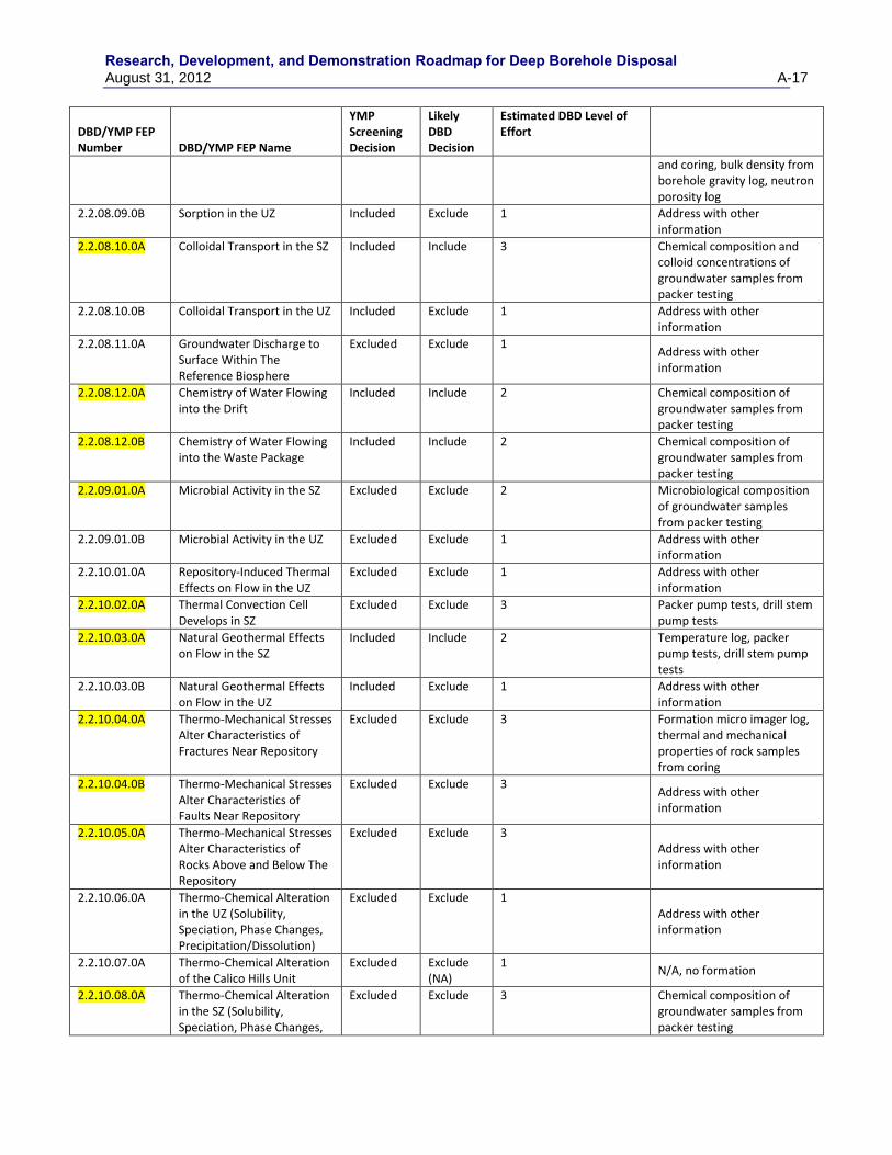
Research, Development, and Demonstration Roadmap for Deep Borehole Disposal August 31, 2012 A-17
DBD/YMP FEP Number DBD/YMP FEP Name
YMP Screening Decision
Likely DBD Decision
Estimated DBD Level of Effort
and coring, bulk density from borehole gravity log, neutron porosity log
2.2.08.09.0B Sorption in the UZ Included Exclude 1 Address with other information
2.2.08.10.0A Colloidal Transport in the SZ Included Include 3 Chemical composition and colloid concentrations of groundwater samples from packer testing
2.2.08.10.0B Colloidal Transport in the UZ Included Exclude 1 Address with other information
2.2.08.11.0A Groundwater Discharge to Surface Within The Reference Biosphere
Excluded Exclude 1 Address with other information
2.2.08.12.0A Chemistry of Water Flowing into the Drift
Included Include 2 Chemical composition of groundwater samples from packer testing
2.2.08.12.0B Chemistry of Water Flowing into the Waste Package
Included Include 2 Chemical composition of groundwater samples from packer testing
2.2.09.01.0A Microbial Activity in the SZ Excluded Exclude 2 Microbiological composition of groundwater samples from packer testing
2.2.09.01.0B Microbial Activity in the UZ Excluded Exclude 1 Address with other information
2.2.10.01.0A Repository-Induced Thermal Effects on Flow in the UZ
Excluded Exclude 1 Address with other information
2.2.10.02.0A Thermal Convection Cell Develops in SZ
Excluded Exclude 3 Packer pump tests, drill stem pump tests
2.2.10.03.0A Natural Geothermal Effects on Flow in the SZ
Included Include 2 Temperature log, packer pump tests, drill stem pump tests
2.2.10.03.0B Natural Geothermal Effects on Flow in the UZ
Included Exclude 1 Address with other information
2.2.10.04.0A Thermo-Mechanical Stresses Alter Characteristics of Fractures Near Repository
Excluded Exclude 3 Formation micro imager log, thermal and mechanical properties of rock samples from coring
2.2.10.04.0B Thermo-Mechanical Stresses Alter Characteristics of Faults Near Repository
Excluded Exclude 3 Address with other information
2.2.10.05.0A Thermo-Mechanical Stresses Alter Characteristics of Rocks Above and Below The Repository
Excluded Exclude 3 Address with other information
2.2.10.06.0A Thermo-Chemical Alteration in the UZ (Solubility, Speciation, Phase Changes, Precipitation/Dissolution)
Excluded Exclude 1 Address with other information
2.2.10.07.0A Thermo-Chemical Alteration of the Calico Hills Unit
Excluded Exclude (NA)
1 N/A, no formation
2.2.10.08.0A Thermo-Chemical Alteration in the SZ (Solubility, Speciation, Phase Changes,
Excluded Exclude 3 Chemical composition of groundwater samples from packer testing
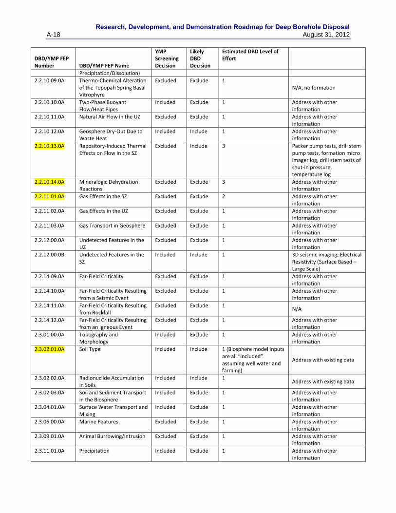
Research, Development, and Demonstration Roadmap for Deep Borehole Disposal
A-18 August 31, 2012
DBD/YMP FEP Number DBD/YMP FEP Name
YMP Screening Decision
Likely DBD Decision
Estimated DBD Level of Effort
Precipitation/Dissolution)
2.2.10.09.0A Thermo-Chemical Alteration of the Topopah Spring Basal Vitrophyre
Excluded Exclude 1 N/A, no formation
2.2.10.10.0A Two-Phase Buoyant Flow/Heat Pipes
Included Exclude 1 Address with other information
2.2.10.11.0A Natural Air Flow in the UZ Excluded Exclude 1 Address with other information
2.2.10.12.0A Geosphere Dry-Out Due to Waste Heat
Included Include 1 Address with other information
2.2.10.13.0A Repository-Induced Thermal Effects on Flow in the SZ
Excluded Include 3 Packer pump tests, drill stem pump tests, formation micro imager log, drill stem tests of shut-in pressure, temperature log
2.2.10.14.0A Mineralogic Dehydration Reactions
Excluded Exclude 3 Address with other information
2.2.11.01.0A Gas Effects in the SZ Excluded Exclude 2 Address with other information
2.2.11.02.0A Gas Effects in the UZ Excluded Exclude 1 Address with other information
2.2.11.03.0A Gas Transport in Geosphere Excluded Exclude 1 Address with other information
2.2.12.00.0A Undetected Features in the UZ
Excluded Exclude 1 Address with other information
2.2.12.00.0B Undetected Features in the SZ
Included Include 1 3D seismic imaging; Electrical Resistivity (Surface Based – Large Scale)
2.2.14.09.0A Far-Field Criticality Excluded Exclude 1 Address with other information
2.2.14.10.0A Far-Field Criticality Resulting from a Seismic Event
Excluded Exclude 1 Address with other information
2.2.14.11.0A Far-Field Criticality Resulting from Rockfall
Excluded Exclude 1 N/A
2.2.14.12.0A Far-Field Criticality Resulting from an Igneous Event
Excluded Exclude 1 Address with other information
2.3.01.00.0A Topography and Morphology
Included Exclude 1 Address with other information
2.3.02.01.0A Soil Type Included Include 1 (Biosphere model inputs are all “included” assuming well water and farming)
Address with existing data
2.3.02.02.0A Radionuclide Accumulation in Soils
Included Include 1 Address with existing data
2.3.02.03.0A Soil and Sediment Transport in the Biosphere
Included Exclude 1 Address with other information
2.3.04.01.0A Surface Water Transport and Mixing
Included Exclude 1 Address with other information
2.3.06.00.0A Marine Features Excluded Exclude 1 Address with other information
2.3.09.01.0A Animal Burrowing/Intrusion Excluded Exclude 1 Address with other information
2.3.11.01.0A Precipitation Included Exclude 1 Address with other information
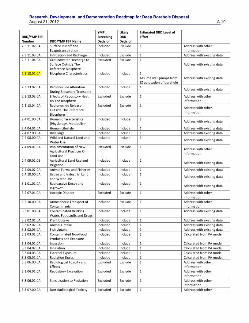
Research, Development, and Demonstration Roadmap for Deep Borehole Disposal August 31, 2012 A-19
DBD/YMP FEP Number DBD/YMP FEP Name
YMP Screening Decision
Likely DBD Decision
Estimated DBD Level of Effort
2.3.11.02.0A Surface Runoff and Evapotranspiration
Included Exclude 1 Address with other information
2.3.11.03.0A Infiltration and Recharge Included Exclude 1 Address with existing data
2.3.11.04.0A Groundwater Discharge to Surface Outside The Reference Biosphere
Excluded Exclude 1 Address with existing data
2.3.13.01.0A Biosphere Characteristics Included Include 1 Assume well pumps from SZ at location of borehole
Address with existing data
2.3.13.02.0A Radionuclide Alteration During Biosphere Transport
Included Include 1 Address with existing data
2.3.13.03.0A Effects of Repository Heat on The Biosphere
Excluded Exclude 1 Address with other information
2.3.13.04.0A Radionuclide Release Outside The Reference Biosphere
Excluded Exclude 1 Address with other information
2.4.01.00.0A Human Characteristics (Physiology, Metabolism)
Included Include 1 Address with existing data
2.4.04.01.0A Human Lifestyle Included Include 1 Address with existing data
2.4.07.00.0A Dwellings Included Include 1 Address with existing data
2.4.08.00.0A Wild and Natural Land and Water Use
Included Include 1 Address with existing data
2.4.09.01.0A Implementation of New Agricultural Practices Or Land Use
Excluded Exclude 1 Address with other information
2.4.09.01.0B Agricultural Land Use and Irrigation
Included Include 1 Address with existing data
2.4.09.02.0A Animal Farms and Fisheries Included Include 1 Address with existing data
2.4.10.00.0A Urban and Industrial Land and Water Use
Included Include 1 Address with existing data
3.1.01.01.0A Radioactive Decay and Ingrowth
Included Include 1 Address with existing data
3.2.07.01.0A Isotopic Dilution Excluded Exclude 1 Address with other information
3.2.10.00.0A Atmospheric Transport of Contaminants
Included Exclude 1 Address with other information
3.3.01.00.0A Contaminated Drinking Water, Foodstuffs and Drugs
Included Include 1 Address with existing data
3.3.02.01.0A Plant Uptake Included Include 1 Address with existing data
3.3.02.02.0A Animal Uptake Included Include 1 Address with existing data
3.3.02.03.0A Fish Uptake Included Include 1 Address with existing data
3.3.03.01.0A Contaminated Non-Food Products and Exposure
Included Include 1 Calculated from PA model
3.3.04.01.0A Ingestion Included Include 1 Calculated from PA model
3.3.04.02.0A Inhalation Included Include 1 Calculated from PA model
3.3.04.03.0A External Exposure Included Include 1 Calculated from PA model
3.3.05.01.0A Radiation Doses Included Include 1 Calculated from PA model
3.3.06.00.0A Radiological Toxicity and Effects
Excluded Exclude 1 Address with other information
3.3.06.01.0A Repository Excavation Excluded Exclude 1 Address with other information
3.3.06.02.0A Sensitization to Radiation Excluded Exclude 1 Address with other information
3.3.07.00.0A Non-Radiological Toxicity Excluded Exclude 1 Address with other

Research, Development, and Demonstration Roadmap for Deep Borehole Disposal
A-20 August 31, 2012
DBD/YMP FEP Number DBD/YMP FEP Name
YMP Screening Decision
Likely DBD Decision
Estimated DBD Level of Effort
and Effects information
3.3.08.00.0A Radon and Radon Decay Product Exposure
Included Include 1 Calculated from PA model
Highlighted entry indicates key FEP for Deep Borehole Disposal (Brady et al., 2009)
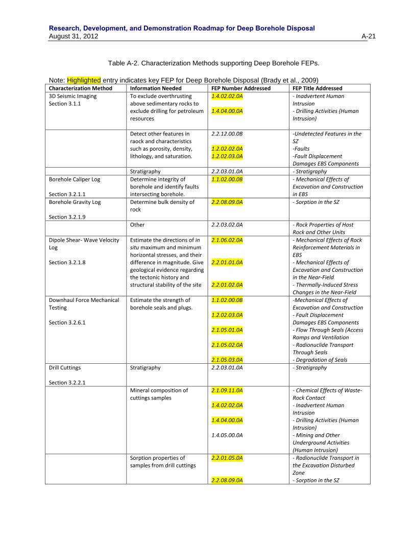
Research, Development, and Demonstration Roadmap for Deep Borehole Disposal August 31, 2012 A-21
Table A-2. Characterization Methods supporting Deep Borehole FEPs.
Note: Highlighted entry indicates key FEP for Deep Borehole Disposal (Brady et al., 2009) Characterization Method Information Needed FEP Number Addressed FEP Title Addressed
3D Seismic Imaging Section 3.1.1
To exclude overthrusting above sedimentary rocks to exclude drilling for petroleum resources
1.4.02.02.0A 1.4.04.00.0A
- Inadvertent Human Intrusion - Drilling Activities (Human Intrusion)
Detect other features in raock and characteristics such as porosity, density, lithology, and saturation.
2.2.12.00.0B 1.2.02.02.0A 1.2.02.03.0A
-Undetected Features in the SZ -Faults -Fault Displacement Damages EBS Components
Stratigraphy 2.2.03.01.0A - Stratigraphy
Borehole Caliper Log Section 3.2.1.1
Determine integrity of borehole and identify faults intersecting borehole.
1.1.02.00.0B - Mechanical Effects of Excavation and Construction in EBS
Borehole Gravity Log Section 3.2.1.9
Determine bulk density of rock
2.2.08.09.0A - Sorption in the SZ
Other 2.2.03.02.0A - Rock Properties of Host Rock and Other Units
Dipole Shear- Wave Velocity Log Section 3.2.1.8
Estimate the directions of in situ maximum and minimum horizontal stresses, and their difference in magnitude. Give geological evidence regarding the tectonic history and structural stability of the site
2.1.06.02.0A 2.2.01.01.0A 2.2.01.02.0A
- Mechanical Effects of Rock Reinforcement Materials in EBS - Mechanical Effects of Excavation and Construction in the Near-Field - Thermally-Induced Stress Changes in the Near-Field
Downhaul Force Mechanical Testing Section 3.2.6.1
Estimate the strength of borehole seals and plugs.
1.1.02.00.0B 1.2.02.03.0A 2.1.05.01.0A 2.1.05.02.0A 2.1.05.03.0A
-Mechanical Effects of Excavation and Construction - Fault Displacement Damages EBS Components - Flow Through Seals (Access Ramps and Ventilation - Radionuclide Transport Through Seals - Degradation of Seals
Drill Cuttings Section 3.2.2.1
Stratigraphy 2.2.03.01.0A - Stratigraphy
Mineral composition of cuttings samples
2.1.09.11.0A 1.4.02.02.0A 1.4.04.00.0A 1.4.05.00.0A
- Chemical Effects of Waste-Rock Contact - Inadvertent Human Intrusion - Drilling Activities (Human Intrusion) - Mining and Other Underground Activities (Human Intrusion)
Sorption properties of samples from drill cuttings
2.2.01.05.0A 2.2.08.09.0A
- Radionuclide Transport in the Excavation Disturbed Zone - Sorption in the SZ

Research, Development, and Demonstration Roadmap for Deep Borehole Disposal
A-22 August 31, 2012
Other basic rock properties 2.2.03.02.0A - Rock Properties of Host Rock and Other Units
Drill Stem Pump Tests Section 3.2.3.2
Provide formation pressure, formation permeability, and water chemistry
2.2.10.03.0A 2.1.08.01.0A 2.2.07.12.0A 2.1.08.09.0A 2.1.09.08.0B 2.1.11.09.0A 2.1.11.09.0C 2.1.11.10.0A 2.2.10.13.0A 2.2.07.15.0A 2.2.10.02.0A
- Natural Geothermal Effects on Flow in the SZ - Water Influx at the Repository - Saturated Groundwater Flow in the Geosphere - Saturated Flow in the EBS - Advection of Dissolved Radionuclides in EBS - Thermal Effects on Flow in the EBS - Thermally Driven Flow (Convection) in Drifts - Thermal Effects on Transport in EBS - Repository-Induced Thermal Effects on Flow in the SZ - Advection and Dispersion in the SZ - Thermal Convection Cell Develops in SZ
Drill Stem Tests of Shut-In Pressure Section 3.2.3.1
Determine hydraulic conductivity (horizontal and vertical), specific storage or storativity, and transmissivity
2.1.08.03.0A 2.1.07.04.0A 2.2.07.12.0A 2.1.08.09.0A 2.1.09.08.0B 2.1.11.09.0A 2.1.11.09.0C 2.1.11.10.0A 2.2.10.13.0A 2.2.07.15.0A
- Repository Dry-Out Due to Waste Heat - Hydrostatic Pressure on Waste Package - Saturated Groundwater Flow in the Geosphere - Saturated Flow in the EBS - Advection of Dissolved Radionuclides in EBS - Thermal Effects on Flow in the EBS - Thermally Driven Flow (Convection) in Drifts - Thermal Effects on Transport in EBS - Repository-Induced Thermal Effects on Flow in the SZ - Advection and Dispersion in the SZ
Electrical Resistivity Profile (Surface Based – Large Scale)
To exclude overthrusting above sedimentary rocks to exclude drilling for petroleum resources
1.4.02.02.0A 1.4.04.00.0A
- Inadvertent Human Intrusion - Drilling Activities (Human Intrusion)
Detect other features in rock such as faults
2.2.12.00.0B 1.2.02.02.0A 1.2.02.03.0A
-Undetected Features in the SZ -Faults -Fault Displacement Damages EBS Components
stratigraphy 2.2.03.01.0A - Stratigraphy
Fluid Pressure Drawdown Test of Effective Permeability Section 3.2.6.2
Test of effective permeability of seals
1.1.02.00.0B 2.1.05.01.0A
- Mechanical Effects of Excavation and Construction in EBS - Flow Through Seals (Access Ramps and Ventilation
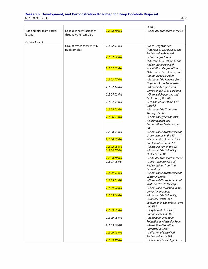
Research, Development, and Demonstration Roadmap for Deep Borehole Disposal August 31, 2012 A-23
Shafts)
Fluid Samples from Packer Testing Section 3.2.2.3
Colloid concentrations of Groundwater samples
2.2.08.10.0A - Colloidal Transport in the SZ
Groundwater chemistry in fluid samples
2.1.02.01.0A 2.1.02.02.0A 2.1.02.03.0A 2.1.02.07.0A 2.1.02.14.0A 2.1.04.02.0A 2.1.04.03.0A 2.1.05.02.0A 2.1.06.01.0A 2.2.08.01.0A 2.2.08.03.0A 2.2.08.06.0A 2.2.08.07.0A 2.2.08.10.0A 2.2.07.06.0B 2.1.09.01.0A 2.1.09.01.0B 2.1.09.02.0A 2.1.09.04.0A 2.1.09.05.0A 2.1.09.06.0A 2.1.09.06.0B 2.1.09.08.0A 2.1.09.10.0A
- DSNF Degradation (Alteration, Dissolution, and Radionuclide Release) - CSNF Degradation (Alteration, Dissolution, and Radionuclide Release) - HLW Glass Degradation (Alteration, Dissolution, and Radionuclide Release) - Radionuclide Release from Gap and Grain Boundaries - Microbially Influenced Corrosion (MIC) of Cladding - Chemical Properties and Evolution of Backfill - Erosion or Dissolution of Backfill - Radionuclide Transport Through Seals - Chemical Effects of Rock Reinforcement and Cementitious Materials in EBS - Chemical Characteristics of Groundwater in the SZ - Geochemical Interactions and Evolution in the SZ - Complexation in the SZ - Radionuclide Solubility Limits in the SZ - Colloidal Transport in the SZ - Long-Term Release of Radionuclides from The Repository - Chemical Characteristics of Water in Drifts - Chemical Characteristics of Water in Waste Package - Chemical Interaction With Corrosion Products - Radionuclide Solubility, Solubility Limits, and Speciation in the Waste Form and EBS - Sorption of Dissolved Radionuclides in EBS - Reduction-Oxidation Potential in Waste Package - Reduction-Oxidation Potential in Drifts - Diffusion of Dissolved Radionuclides in EBS - Secondary Phase Effects on
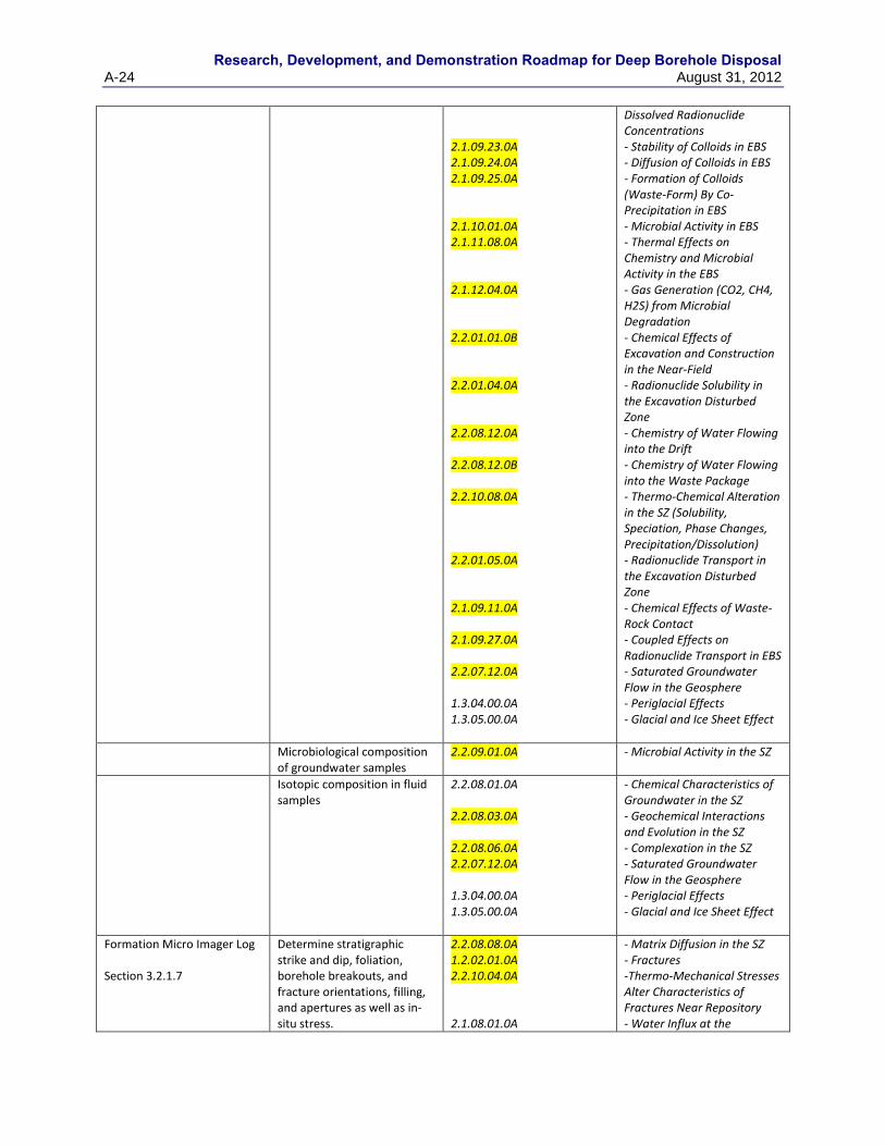
Research, Development, and Demonstration Roadmap for Deep Borehole Disposal
A-24 August 31, 2012
2.1.09.23.0A 2.1.09.24.0A 2.1.09.25.0A 2.1.10.01.0A 2.1.11.08.0A 2.1.12.04.0A 2.2.01.01.0B 2.2.01.04.0A 2.2.08.12.0A 2.2.08.12.0B 2.2.10.08.0A 2.2.01.05.0A 2.1.09.11.0A 2.1.09.27.0A 2.2.07.12.0A 1.3.04.00.0A 1.3.05.00.0A
Dissolved Radionuclide Concentrations - Stability of Colloids in EBS - Diffusion of Colloids in EBS - Formation of Colloids (Waste-Form) By Co-Precipitation in EBS - Microbial Activity in EBS - Thermal Effects on Chemistry and Microbial Activity in the EBS - Gas Generation (CO2, CH4, H2S) from Microbial Degradation - Chemical Effects of Excavation and Construction in the Near-Field - Radionuclide Solubility in the Excavation Disturbed Zone - Chemistry of Water Flowing into the Drift - Chemistry of Water Flowing into the Waste Package - Thermo-Chemical Alteration in the SZ (Solubility, Speciation, Phase Changes, Precipitation/Dissolution) - Radionuclide Transport in the Excavation Disturbed Zone - Chemical Effects of Waste-Rock Contact - Coupled Effects on Radionuclide Transport in EBS - Saturated Groundwater Flow in the Geosphere - Periglacial Effects - Glacial and Ice Sheet Effect
Microbiological composition of groundwater samples
2.2.09.01.0A - Microbial Activity in the SZ
Isotopic composition in fluid samples
2.2.08.01.0A 2.2.08.03.0A 2.2.08.06.0A 2.2.07.12.0A 1.3.04.00.0A 1.3.05.00.0A
- Chemical Characteristics of Groundwater in the SZ - Geochemical Interactions and Evolution in the SZ - Complexation in the SZ - Saturated Groundwater Flow in the Geosphere - Periglacial Effects - Glacial and Ice Sheet Effect
Formation Micro Imager Log Section 3.2.1.7
Determine stratigraphic strike and dip, foliation, borehole breakouts, and fracture orientations, filling, and apertures as well as in-situ stress.
2.2.08.08.0A 1.2.02.01.0A 2.2.10.04.0A 2.1.08.01.0A
- Matrix Diffusion in the SZ - Fractures -Thermo-Mechanical Stresses Alter Characteristics of Fractures Near Repository - Water Influx at the
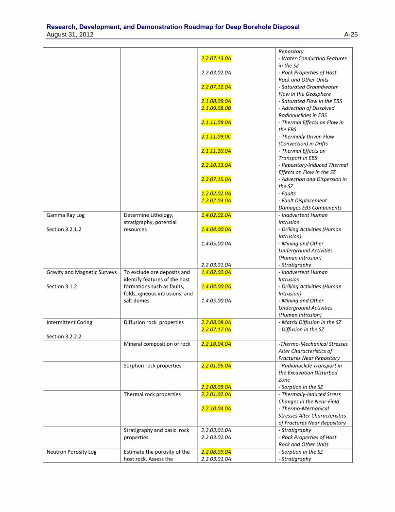
Research, Development, and Demonstration Roadmap for Deep Borehole Disposal August 31, 2012 A-25
2.2.07.13.0A 2.2.03.02.0A 2.2.07.12.0A 2.1.08.09.0A 2.1.09.08.0B 2.1.11.09.0A 2.1.11.09.0C 2.1.11.10.0A 2.2.10.13.0A 2.2.07.15.0A 1.2.02.02.0A 1.2.02.03.0A
Repository - Water-Conducting Features in the SZ - Rock Properties of Host Rock and Other Units - Saturated Groundwater Flow in the Geosphere - Saturated Flow in the EBS - Advection of Dissolved Radionuclides in EBS - Thermal Effects on Flow in the EBS - Thermally Driven Flow (Convection) in Drifts - Thermal Effects on Transport in EBS - Repository-Induced Thermal Effects on Flow in the SZ - Advection and Dispersion in the SZ - Faults - Fault Displacement Damages EBS Components
Gamma Ray Log Section 3.2.1.2
Determine Lithology, stratigraphy, potential resources
1.4.02.02.0A 1.4.04.00.0A 1.4.05.00.0A 2.2.03.01.0A
- Inadvertent Human Intrusion - Drilling Activities (Human Intrusion) - Mining and Other Underground Activities (Human Intrusion) - Stratigraphy
Gravity and Magnetic Surveys Section 3.1.2
To exclude ore deposits and identify features of the host formations such as faults, folds, igneous intrusions, and salt domes
1.4.02.02.0A 1.4.04.00.0A 1.4.05.00.0A
- Inadvertent Human Intrusion - Drilling Activities (Human Intrusion) - Mining and Other Underground Activities (Human Intrusion)
Intermittent Coring Section 3.2.2.2
Diffusion rock properties 2.2.08.08.0A 2.2.07.17.0A
- Matrix Diffusion in the SZ - Diffusion in the SZ
Mineral composition of rock 2.2.10.04.0A -Thermo-Mechanical Stresses Alter Characteristics of Fractures Near Repository
Sorption rock properties 2.2.01.05.0A 2.2.08.09.0A
- Radionuclide Transport in the Excavation Disturbed Zone - Sorption in the SZ
Thermal rock properties 2.2.01.02.0A 2.2.10.04.0A
- Thermally-Induced Stress Changes in the Near-Field - Thermo-Mechanical Stresses Alter Characteristics of Fractures Near Repository
Stratigraphy and basic rock properties
2.2.03.01.0A 2.2.03.02.0A
- Stratigraphy - Rock Properties of Host Rock and Other Units
Neutron Porosity Log
Estimate the porosity of the host rock. Assess the
2.2.08.09.0A 2.2.03.01.0A
- Sorption in the SZ - Stratigraphy
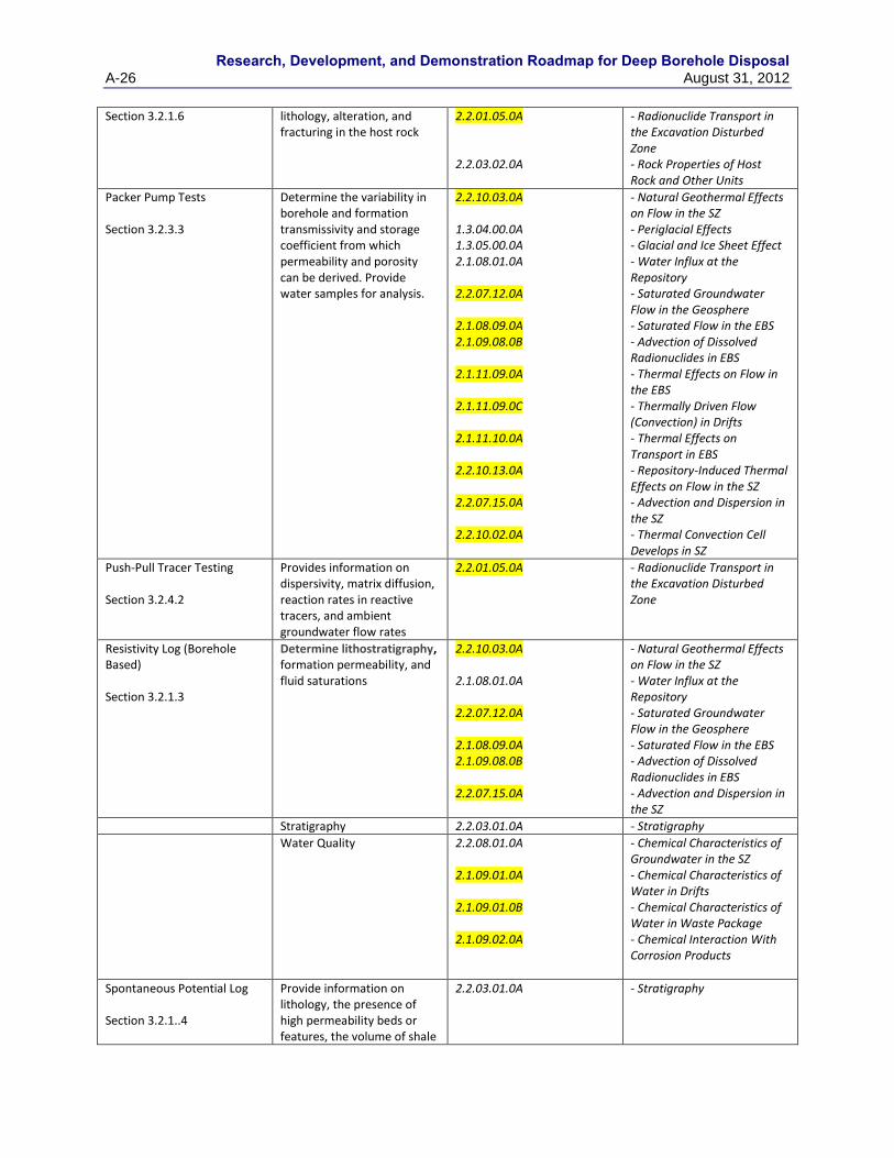
Research, Development, and Demonstration Roadmap for Deep Borehole Disposal
A-26 August 31, 2012
Section 3.2.1.6 lithology, alteration, and fracturing in the host rock
2.2.01.05.0A 2.2.03.02.0A
- Radionuclide Transport in the Excavation Disturbed Zone - Rock Properties of Host Rock and Other Units
Packer Pump Tests Section 3.2.3.3
Determine the variability in borehole and formation transmissivity and storage coefficient from which permeability and porosity can be derived. Provide water samples for analysis.
2.2.10.03.0A 1.3.04.00.0A 1.3.05.00.0A 2.1.08.01.0A 2.2.07.12.0A 2.1.08.09.0A 2.1.09.08.0B 2.1.11.09.0A 2.1.11.09.0C 2.1.11.10.0A 2.2.10.13.0A 2.2.07.15.0A 2.2.10.02.0A
- Natural Geothermal Effects on Flow in the SZ - Periglacial Effects - Glacial and Ice Sheet Effect - Water Influx at the Repository - Saturated Groundwater Flow in the Geosphere - Saturated Flow in the EBS - Advection of Dissolved Radionuclides in EBS - Thermal Effects on Flow in the EBS - Thermally Driven Flow (Convection) in Drifts - Thermal Effects on Transport in EBS - Repository-Induced Thermal Effects on Flow in the SZ - Advection and Dispersion in the SZ - Thermal Convection Cell Develops in SZ
Push-Pull Tracer Testing Section 3.2.4.2
Provides information on dispersivity, matrix diffusion, reaction rates in reactive tracers, and ambient groundwater flow rates
2.2.01.05.0A - Radionuclide Transport in the Excavation Disturbed Zone
Resistivity Log (Borehole Based) Section 3.2.1.3
Determine lithostratigraphy, formation permeability, and fluid saturations
2.2.10.03.0A 2.1.08.01.0A 2.2.07.12.0A 2.1.08.09.0A 2.1.09.08.0B 2.2.07.15.0A
- Natural Geothermal Effects on Flow in the SZ - Water Influx at the Repository - Saturated Groundwater Flow in the Geosphere - Saturated Flow in the EBS - Advection of Dissolved Radionuclides in EBS - Advection and Dispersion in the SZ
Stratigraphy 2.2.03.01.0A - Stratigraphy
Water Quality 2.2.08.01.0A 2.1.09.01.0A 2.1.09.01.0B 2.1.09.02.0A
- Chemical Characteristics of Groundwater in the SZ - Chemical Characteristics of Water in Drifts - Chemical Characteristics of Water in Waste Package - Chemical Interaction With Corrosion Products
Spontaneous Potential Log Section 3.2.1..4
Provide information on lithology, the presence of high permeability beds or features, the volume of shale
2.2.03.01.0A - Stratigraphy
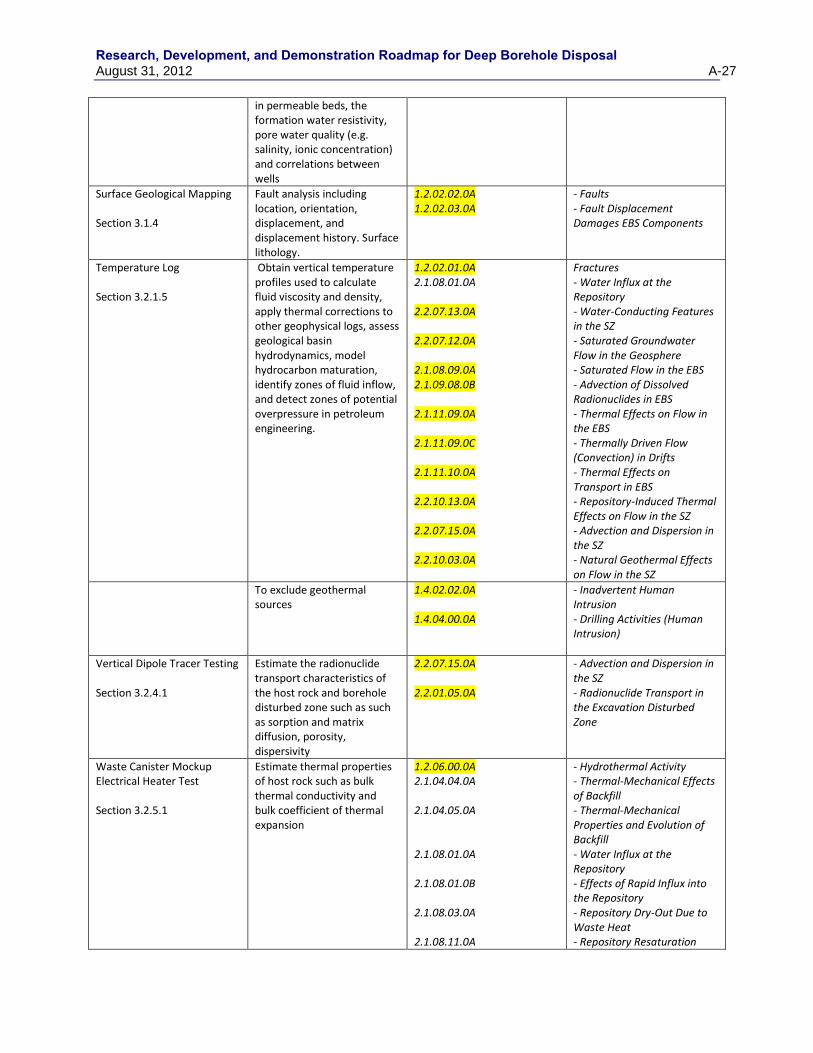
Research, Development, and Demonstration Roadmap for Deep Borehole Disposal August 31, 2012 A-27
in permeable beds, the formation water resistivity, pore water quality (e.g. salinity, ionic concentration) and correlations between wells
Surface Geological Mapping Section 3.1.4
Fault analysis including location, orientation, displacement, and displacement history. Surface lithology.
1.2.02.02.0A 1.2.02.03.0A
- Faults - Fault Displacement Damages EBS Components
Temperature Log Section 3.2.1.5
Obtain vertical temperature profiles used to calculate fluid viscosity and density, apply thermal corrections to other geophysical logs, assess geological basin hydrodynamics, model hydrocarbon maturation, identify zones of fluid inflow, and detect zones of potential overpressure in petroleum engineering.
1.2.02.01.0A 2.1.08.01.0A 2.2.07.13.0A 2.2.07.12.0A 2.1.08.09.0A 2.1.09.08.0B 2.1.11.09.0A 2.1.11.09.0C 2.1.11.10.0A 2.2.10.13.0A 2.2.07.15.0A 2.2.10.03.0A
Fractures - Water Influx at the Repository - Water-Conducting Features in the SZ - Saturated Groundwater Flow in the Geosphere - Saturated Flow in the EBS - Advection of Dissolved Radionuclides in EBS - Thermal Effects on Flow in the EBS - Thermally Driven Flow (Convection) in Drifts - Thermal Effects on Transport in EBS - Repository-Induced Thermal Effects on Flow in the SZ - Advection and Dispersion in the SZ - Natural Geothermal Effects on Flow in the SZ
To exclude geothermal sources
1.4.02.02.0A 1.4.04.00.0A
- Inadvertent Human Intrusion - Drilling Activities (Human Intrusion)
Vertical Dipole Tracer Testing Section 3.2.4.1
Estimate the radionuclide transport characteristics of the host rock and borehole disturbed zone such as such as sorption and matrix diffusion, porosity, dispersivity
2.2.07.15.0A 2.2.01.05.0A
- Advection and Dispersion in the SZ - Radionuclide Transport in the Excavation Disturbed Zone
Waste Canister Mockup Electrical Heater Test Section 3.2.5.1
Estimate thermal properties of host rock such as bulk thermal conductivity and bulk coefficient of thermal expansion
1.2.06.00.0A 2.1.04.04.0A 2.1.04.05.0A 2.1.08.01.0A 2.1.08.01.0B 2.1.08.03.0A 2.1.08.11.0A
- Hydrothermal Activity - Thermal-Mechanical Effects of Backfill - Thermal-Mechanical Properties and Evolution of Backfill - Water Influx at the Repository - Effects of Rapid Influx into the Repository - Repository Dry-Out Due to Waste Heat - Repository Resaturation

Research, Development, and Demonstration Roadmap for Deep Borehole Disposal
A-28 August 31, 2012
2.1.09.12.0A 2.1.11.07.0A 2.1.11.09.0A 2.1.11.09.0C 2.1.11.10.0A 2.2.01.02.0A 2.2.07.11.0A 2.2.10.02.0A 2.2.10.03.0A 2.2.10.04.0A 2.2.10.04.0B 2.2.10.05.0A 2.2.10.08.0A 2.2.10.12.0A 2.2.10.13.0A
Due to Waste Cooling - Rind (Chemically Altered Zone) Forms in the Near-Field - Thermal Expansion/Stress of in-Drift EBS Components - Thermal Effects on Flow in the EBS - Thermally Driven Flow (Convection) in Drifts - Thermal Effects on Transport in EBS - Thermally-Induced Stress Changes in the Near-Field - Resaturation of Geosphere Dry-Out Zone - Thermal Convection Cell Develops in SZ - Natural Geothermal Effects on Flow in the SZ - Thermo-Mechanical Stresses Alter Characteristics of Fractures Near Repository - Thermo-Mechanical Stresses Alter Characteristics of Faults Near Repository - Thermo-Mechanical Stresses Alter Characteristics of Rocks Above and Below The Repository - Thermo-Chemical Alteration in the SZ (Solubility, Speciation, Phase Changes, Precipitation/Dissolution) - Geosphere Dry-Out Due to Waste Heat - Repository-Induced Thermal Effects on Flow in the SZ
Highlighted entry indicates key FEP for Deep Borehole Disposal (Brady et al., 2009)
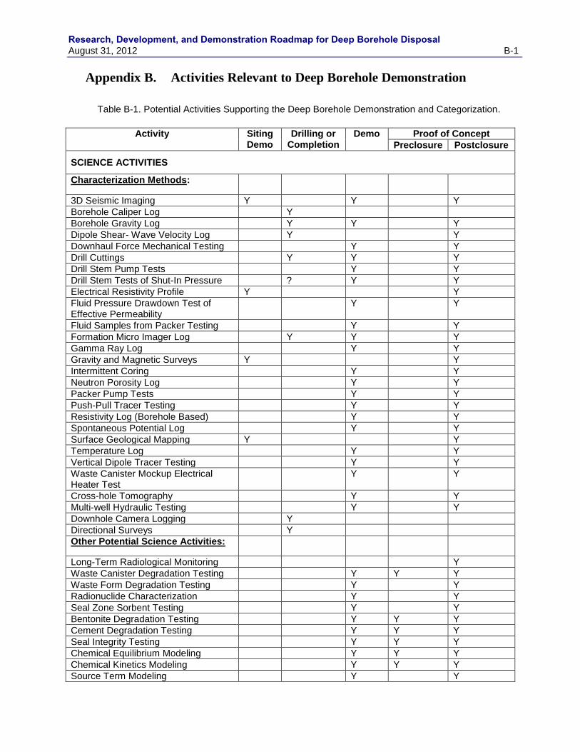
Research, Development, and Demonstration Roadmap for Deep Borehole Disposal August 31, 2012 B-1
Appendix B. Activities Relevant to Deep Borehole Demonstration
Table B-1. Potential Activities Supporting the Deep Borehole Demonstration and Categorization.
Activity Siting
Demo Drilling or
Completion Demo Proof of Concept
Preclosure Postclosure
SCIENCE ACTIVITIES
Characterization Methods:
3D Seismic Imaging Y Y Y
Borehole Caliper Log Y
Borehole Gravity Log Y Y Y
Dipole Shear- Wave Velocity Log Y Y
Downhaul Force Mechanical Testing Y Y
Drill Cuttings Y Y Y
Drill Stem Pump Tests Y Y
Drill Stem Tests of Shut-In Pressure ? Y Y
Electrical Resistivity Profile Y Y
Fluid Pressure Drawdown Test of Effective Permeability
Y Y
Fluid Samples from Packer Testing Y Y
Formation Micro Imager Log Y Y Y
Gamma Ray Log Y Y
Gravity and Magnetic Surveys Y Y
Intermittent Coring Y Y
Neutron Porosity Log Y Y
Packer Pump Tests Y Y
Push-Pull Tracer Testing Y Y
Resistivity Log (Borehole Based) Y Y
Spontaneous Potential Log Y Y
Surface Geological Mapping Y Y
Temperature Log Y Y
Vertical Dipole Tracer Testing Y Y
Waste Canister Mockup Electrical Heater Test
Y Y
Cross-hole Tomography Y Y
Multi-well Hydraulic Testing Y Y
Downhole Camera Logging Y
Directional Surveys Y
Other Potential Science Activities:
Long-Term Radiological Monitoring Y
Waste Canister Degradation Testing Y Y Y
Waste Form Degradation Testing Y Y
Radionuclide Characterization Y Y
Seal Zone Sorbent Testing Y Y
Bentonite Degradation Testing Y Y Y
Cement Degradation Testing Y Y Y
Seal Integrity Testing Y Y Y
Chemical Equilibrium Modeling Y Y Y
Chemical Kinetics Modeling Y Y Y
Source Term Modeling Y Y
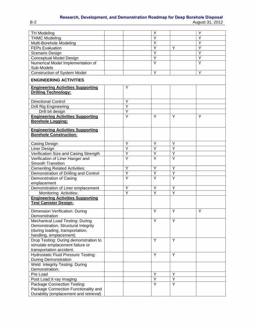
Research, Development, and Demonstration Roadmap for Deep Borehole Disposal
B-2 August 31, 2012
TH Modeling Y Y
THMC Modeling Y Y
Multi-Borehole Modeling Y Y
FEPs Evaluation Y Y Y
Scenario Design Y Y
Conceptual Model Design Y Y
Numerical Model Implementation of Sub-Models
Y Y
Construction of System Model Y Y
ENGINEERING ACTIVITIES
Engineering Activities Supporting Drilling Technology:
Y
Directional Control Y
Drill Rig Engineering Y
Drill bit design Y
Engineering Activities Supporting Borehole Logging:
Y Y Y Y
Engineering Activities Supporting Borehole Construction:
Casing Design Y Y Y
Liner Design Y Y Y
Verification Size and Casing Strength Y Y Y
Verification of Liner Hanger and Smooth Transition
Y Y Y
Cementing Related Activities: Y Y Y
Demonstration of Drilling and Control Y Y Y
Demonstration of Casing emplacement
Y Y Y
Demonstration of Liner emplacement Y Y Y
Monitoring Activities: Y Y Y
Engineering Activities Supporting Test Canister Design:
Dimension Verification: During Demonstration
Y Y Y
Mechanical Load Testing: During Demonstration, Structural Integrity (during loading, transportation, handling, emplacement)
Y Y
Drop Testing: During demonstration to simulate emplacement failure or transportation accident.
Y Y
Hydrostatic Fluid Pressure Testing: During Demonstration
Y Y
Weld Integrity Testing: During Demonstration:
Pre Load Y Y
Post Load:X-ray Imaging Y Y
Package Connection Testing: Package Connection Functionality and Durability (emplacement and retrieval)
Y Y
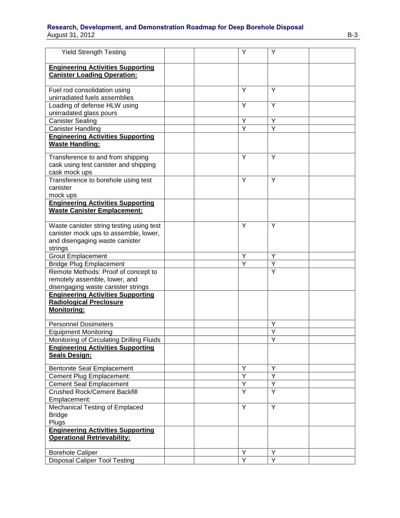
Research, Development, and Demonstration Roadmap for Deep Borehole Disposal August 31, 2012 B-3
Yield Strength Testing
Y Y
Engineering Activities Supporting Canister Loading Operation:
Fuel rod consolidation using unirradiated fuels assemblies
Y Y
Loading of defense HLW using unirradated glass pours
Y Y
Canister Sealing Y Y
Canister Handling Y Y
Engineering Activities Supporting Waste Handling:
Transference to and from shipping cask using test canister and shipping cask mock ups
Y Y
Transference to borehole using test canister mock ups
Y Y
Engineering Activities Supporting Waste Canister Emplacement:
Waste canister string testing using test canister mock ups to assemble, lower, and disengaging waste canister strings
Y Y
Grout Emplacement Y Y
Bridge Plug Emplacement Y Y
Remote Methods: Proof of concept to remotely assemble, lower, and disengaging waste canister strings
Y
Engineering Activities Supporting Radiological Preclosure Monitoring:
Personnel Dosimeters Y
Equipment Monitoring Y
Monitoring of Circulating Drilling Fluids Y
Engineering Activities Supporting Seals Design:
Bentonite Seal Emplacement Y Y
Cement Plug Emplacement: Y Y
Cement Seal Emplacement Y Y
Crushed Rock/Cement Backfill Emplacement:
Y Y
Mechanical Testing of Emplaced Bridge Plugs
Y Y
Engineering Activities Supporting Operational Retrievability:
Borehole Caliper Y Y
Disposal Caliper Tool Testing Y Y

Research, Development, and Demonstration Roadmap for Deep Borehole Disposal
B-4 August 31, 2012
Testing Retrieval Operations: Y Y
Using Drill Rig Y Y
Mining from Surface Y Y
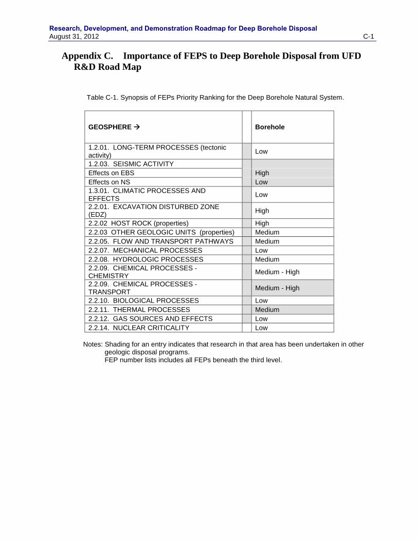
Research, Development, and Demonstration Roadmap for Deep Borehole Disposal August 31, 2012 C-1
Appendix C. Importance of FEPS to Deep Borehole Disposal from UFD
R&D Road Map
Table C-1. Synopsis of FEPs Priority Ranking for the Deep Borehole Natural System.
GEOSPHERE
Borehole
1.2.01. LONG-TERM PROCESSES (tectonic activity)
Low
1.2.03. SEISMIC ACTIVITY
Effects on EBS
High
Effects on NS
Low
1.3.01. CLIMATIC PROCESSES AND EFFECTS
Low
2.2.01. EXCAVATION DISTURBED ZONE (EDZ)
High
2.2.02 HOST ROCK (properties)
High
2.2.03 OTHER GEOLOGIC UNITS (properties)
Medium
2.2.05. FLOW AND TRANSPORT PATHWAYS
Medium
2.2.07. MECHANICAL PROCESSES
Low
2.2.08. HYDROLOGIC PROCESSES
Medium
2.2.09. CHEMICAL PROCESSES - CHEMISTRY
Medium - High
2.2.09. CHEMICAL PROCESSES - TRANSPORT
Medium - High
2.2.10. BIOLOGICAL PROCESSES
Low
2.2.11. THERMAL PROCESSES
Medium
2.2.12. GAS SOURCES AND EFFECTS
Low
2.2.14. NUCLEAR CRITICALITY
Low
Notes: Shading for an entry indicates that research in that area has been undertaken in other
geologic disposal programs. FEP number lists includes all FEPs beneath the third level.
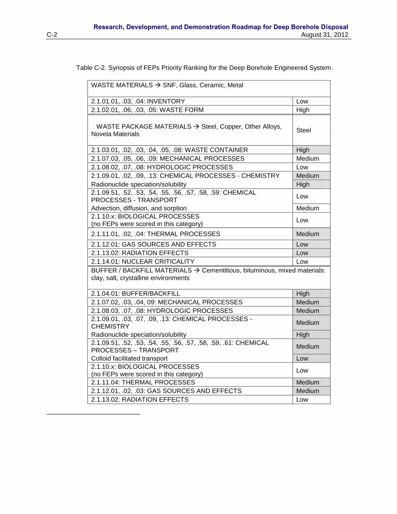
Research, Development, and Demonstration Roadmap for Deep Borehole Disposal
C-2 August 31, 2012
Table C-2. Synopsis of FEPs Priority Ranking for the Deep Borehole Engineered System.
WASTE MATERIALS SNF, Glass, Ceramic, Metal
2.1.01.01, .03, .04: INVENTORY Low
2.1.02.01, .06, .03, .05: WASTE FORM High
WASTE PACKAGE MATERIALS Steel, Copper, Other Alloys, Novela Materials
Steel
2.1.03.01, .02, .03, .04, .05, .08: WASTE CONTAINER High
2.1.07.03, .05, .06, .09: MECHANICAL PROCESSES Medium
2.1.08.02, .07, .08: HYDROLOGIC PROCESSES Low
2.1.09.01, .02, .09, .13: CHEMICAL PROCESSES - CHEMISTRY Medium
Radionuclide speciation/solubility High
2.1.09.51, .52, .53, .54, .55, .56, .57, .58, .59: CHEMICAL PROCESSES - TRANSPORT
Low
Advection, diffusion, and sorption Medium
2.1.10.x: BIOLOGICAL PROCESSES (no FEPs were scored in this category)
Low
2.1.11.01, .02, .04: THERMAL PROCESSES Medium
2.1.12.01: GAS SOURCES AND EFFECTS Low
2.1.13.02: RADIATION EFFECTS Low
2.1.14.01: NUCLEAR CRITICALITY Low
BUFFER / BACKFILL MATERIALS Cementitious, bituminous, mixed materials: clay, salt, crystalline environments
2.1.04.01: BUFFER/BACKFILL High
2.1.07.02, .03, .04, 09: MECHANICAL PROCESSES Medium
2.1.08.03, .07, .08: HYDROLOGIC PROCESSES Medium
2.1.09.01, .03, .07, .09, .13: CHEMICAL PROCESSES - CHEMISTRY
Medium
Radionuclide speciation/solubility High
2.1.09.51, .52, .53, .54, .55, .56, .57, .58, .59, .61: CHEMICAL PROCESSES – TRANSPORT
Medium
Colloid facilitated transport Low
2.1.10.x: BIOLOGICAL PROCESSES (no FEPs were scored in this category)
Low
2.1.11.04: THERMAL PROCESSES Medium
2.1.12.01, .02, .03: GAS SOURCES AND EFFECTS Medium
2.1.13.02: RADIATION EFFECTS Low
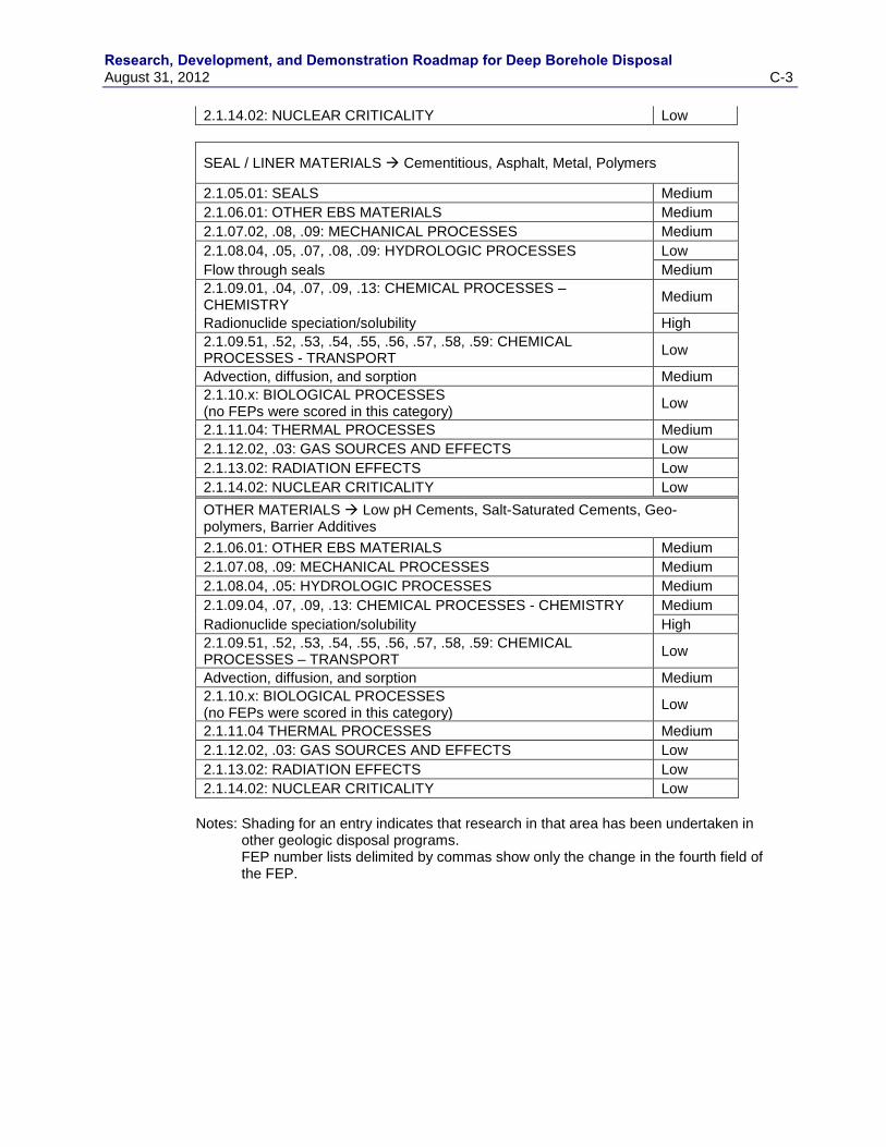
Research, Development, and Demonstration Roadmap for Deep Borehole Disposal August 31, 2012 C-3
2.1.14.02: NUCLEAR CRITICALITY Low
SEAL / LINER MATERIALS Cementitious, Asphalt, Metal, Polymers
2.1.05.01: SEALS Medium
2.1.06.01: OTHER EBS MATERIALS Medium
2.1.07.02, .08, .09: MECHANICAL PROCESSES Medium
2.1.08.04, .05, .07, .08, .09: HYDROLOGIC PROCESSES Low
Flow through seals Medium
2.1.09.01, .04, .07, .09, .13: CHEMICAL PROCESSES – CHEMISTRY
Medium
Radionuclide speciation/solubility High
2.1.09.51, .52, .53, .54, .55, .56, .57, .58, .59: CHEMICAL PROCESSES - TRANSPORT
Low
Advection, diffusion, and sorption Medium
2.1.10.x: BIOLOGICAL PROCESSES (no FEPs were scored in this category)
Low
2.1.11.04: THERMAL PROCESSES Medium
2.1.12.02, .03: GAS SOURCES AND EFFECTS Low
2.1.13.02: RADIATION EFFECTS Low
2.1.14.02: NUCLEAR CRITICALITY Low
OTHER MATERIALS Low pH Cements, Salt-Saturated Cements, Geo-polymers, Barrier Additives
2.1.06.01: OTHER EBS MATERIALS Medium
2.1.07.08, .09: MECHANICAL PROCESSES Medium
2.1.08.04, .05: HYDROLOGIC PROCESSES Medium
2.1.09.04, .07, .09, .13: CHEMICAL PROCESSES - CHEMISTRY Medium
Radionuclide speciation/solubility High
2.1.09.51, .52, .53, .54, .55, .56, .57, .58, .59: CHEMICAL PROCESSES – TRANSPORT
Low
Advection, diffusion, and sorption Medium
2.1.10.x: BIOLOGICAL PROCESSES (no FEPs were scored in this category)
Low
2.1.11.04 THERMAL PROCESSES Medium
2.1.12.02, .03: GAS SOURCES AND EFFECTS Low
2.1.13.02: RADIATION EFFECTS Low
2.1.14.02: NUCLEAR CRITICALITY Low
Notes: Shading for an entry indicates that research in that area has been undertaken in
other geologic disposal programs. FEP number lists delimited by commas show only the change in the fourth field of the FEP.

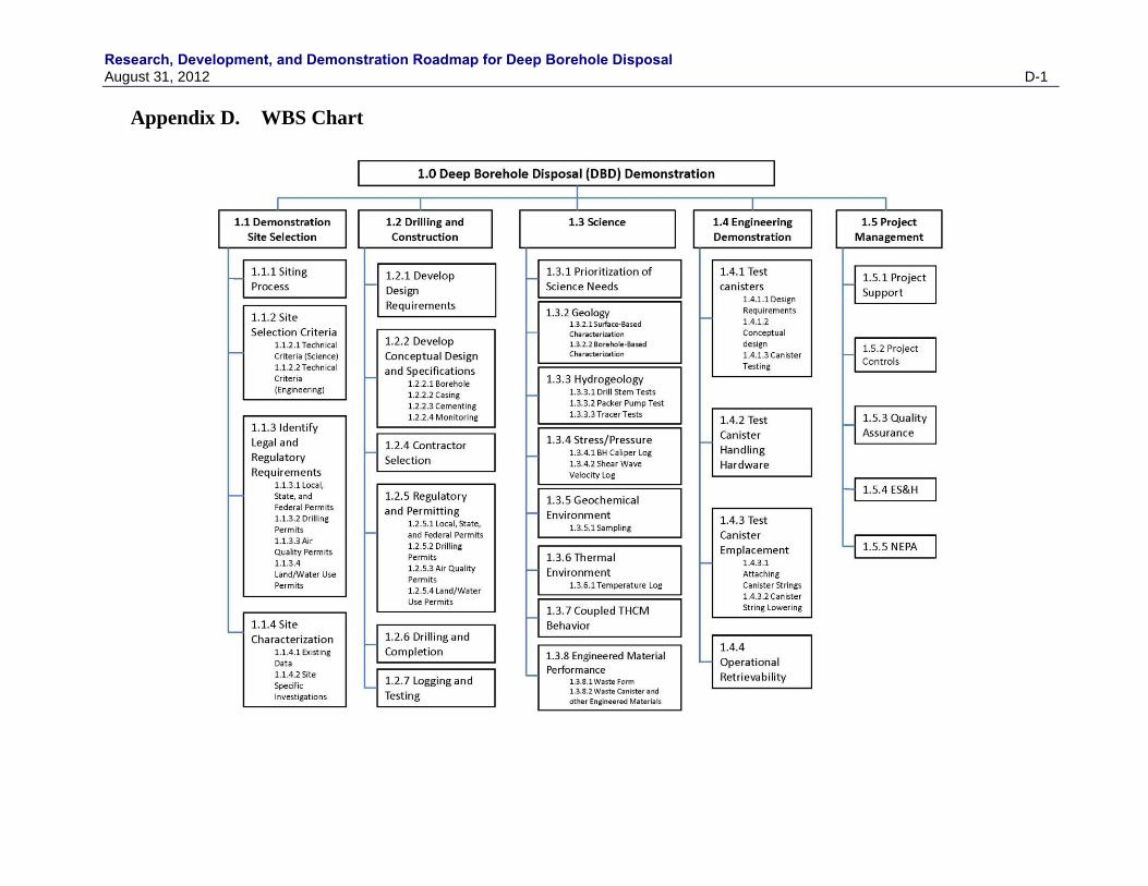
Research, Development, and Demonstration Roadmap for Deep Borehole Disposal August 31, 2012 D-1
Appendix D. WBS Chart


Research, Development, and Demonstration Roadmap for Deep Borehole Disposal August 31, 2012 D-1

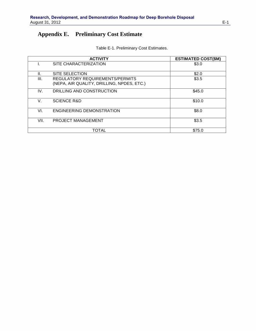
Research, Development, and Demonstration Roadmap for Deep Borehole Disposal August 31, 2012 E-1
Appendix E. Preliminary Cost Estimate
Table E-1. Preliminary Cost Estimates.
ACTIVITY ESTIMATED COST($M)
I. SITE CHARACTERIZATION
$3.0
II. SITE SELECTION $2.0
III. REGULATORY REQUIREMENTS/PERMITS (NEPA, AIR QUALITY, DRILLING, NPDES, ETC.)
$3.5
IV. DRILLING AND CONSTRUCTION
$45.0
V. SCIENCE R&D
$10.0
VI. ENGINEERING DEMONSTRATION
$8.0
VII. PROJECT MANAGEMENT
$3.5
TOTAL $75.0

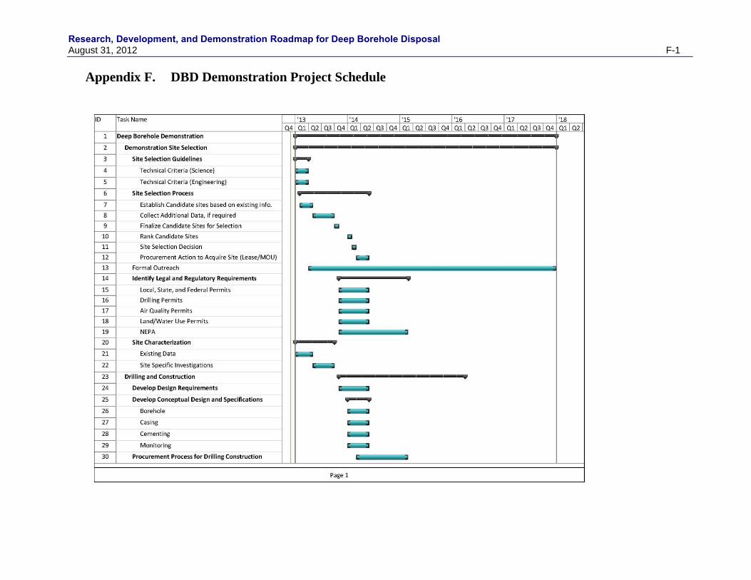
Research, Development, and Demonstration Roadmap for Deep Borehole Disposal August 31, 2012 F-1
Appendix F. DBD Demonstration Project Schedule
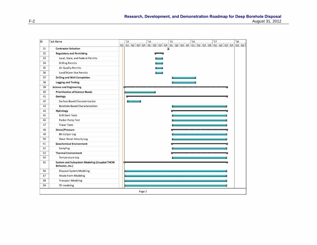
Research, Development, and Demonstration Roadmap for Deep Borehole Disposal
F-2 August 31, 2012
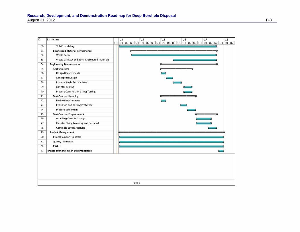
Research, Development, and Demonstration Roadmap for Deep Borehole Disposal August 31, 2012 F-3


![]project-open[ ITSM Development Roadmap](https://img.pdfslide.net/doc/110x75/554ce439b4c905d1488b5501/project-open-itsm-development-roadmap.jpg)