Embed Size (px)
Citation preview

Research in Engineering Design (1997) 9:168-190 © 1997 Springer-Verlag London Limited
Research in
El~gin. eering eslgn
Automated Manufacturabi l i ty Analysis: A Survey
Satyandra K, Gupta, ~ William C. Regli, 2 Diganta Das 3 and Dana S. Nau 4 1 Center for Integrated Manufacturing Decision Systems, The Robotics Institute, Carnegie Mellon University, Pittsburgh, USA; 2 National Institute of Standards and Technology, Manufacturing Systems Integration Division, Gaithersburg, USA; a Department of Mechanical Engineering, University of Maryland, USA; 4 Department of Computer Science, Institute for Advanced Computer Studies and Institute for Systems Research, University of Maryland, USA
Abstract. In the market-place of the 21st century, there is no place for traditional 'over-the-wall' communications between design and manufacturing. In order to 'design it right the very first time', designers must ensure that their produets are both functional and easy to manufacture, Software tools have had some successes in reducing the barriers between design and manufacturing. Manufacturability analysis systems are emerging as one such tool - enabling identification o f potential manufacturing problems' during the design phase and providing suggestions to designers on how to eliminate them.
In this paper, we provide a survey of current state-of-the- art automated manufacturability analysis. We present the historical context in which this area has emerged and outline characteristics to compare and elass~y various systems. We describe the two dominant approaches to automated manu- facturability analysis and overview representative systems based on their application domain. We describe support tools that enhance the effectiveness of manufacturability analysis systems. Finally, we attempt to expose some o f the existing research challenges and future directions.
Keywords. CAD; Concurrent engineering; Design for manufacturing
1. Introduction
Increasing global competition is challenging the manufacturing industry to bring competitively priced, well-designed and well-manufactured products to market in a timely fashion. Although product design incurs only a small fraction of the total product cost, the decisions made during the design phase account for a significant portion of this cost and prove crucial
to the success or failure of the product [162, 153, 168]. Since the cost of making design changes after initia- tion of the product development cycle escalates steeply with time, the ability to make essential changes during the design phase (as opposed to during the production run) translates into significant savings [168]. To achieve this goal, increasing re- search attention is being directed toward the integra- tion of engineering design and manufacturing. These attempts have led to the evolution of design f o r
manufacturabit i ty (DFM) methodologies [8]. D F M invoIves simultaneously considering design goals and manufacturing constraints in order to identify and alleviate manufacturing problems while the product is being designed; thereby reducing the lead time for product development and improving product quality.
Traditionally, the translation of a conceptual de- sign into a final product to be manufactured has been accomplished by iterations between design and man- ufacturing engineers. Often, a designer would com- plete the entire design before passing the blueprints on to a manufacturing department. If the manufac- turing engineers noticed any manufacturing-related problems, they would notify the design team and the design would be sent through another iteration.
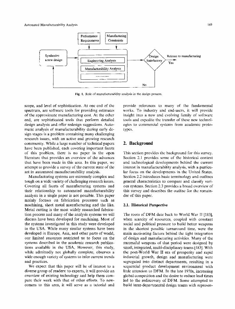
To expedite these time-consuming iterations, a number of software tools have been developed - allowing designers to analyse manufacturability 1 during the design stage. In this paper, we collectively refer to such software tools as automated manu- faeturabi l i ty analysis systems. Figure 1 shows the role of manufacturability analysis systems in the design process. Such systems vary significantly by approach,
Correspondence and offprint requests to." S. K. Gupta, Center for Integrated Manufacturing, The Robotics Institute, Carnegie Mellon University, Pittsburgh, PA 15213, USA. E-mail: [email protected].
1 There seems to be no universal definition of the term manufactur- ability. However, in most cases, manufacturability refers to the design characteristics which indicate how difficult or easy the design is from a manufacturing perspective.
Automated Manufacturability Analysis 169
Synthesize a new design
f Performance Manufacturing Requirements [ Constraints
Engineering Analysis ]
[ Manufacturability Analysis ]
t ................ ]
Fig. I. Role of manufacturability analysis in the design process.
Release to manufacturing v -
Yes
scope, and level of sophistication. At one end of the spectrum, are software tools for providing estimates of the approximate manufacturing cost. At the other end, are sophisticated tools that perform detailed design analysis and offer redesign suggestions. Auto- matic analysis of manufacturability during early de- sign stages is a problem containing many challenging research issues, with an active and growing research community. While a large number of technical papers have been published, each covering important facets of this problem, there is no paper in the open literature that provides an overview of the advances that have been made in this area. In this paper, we attempt to provide a survey of the current state of the art in automated manufacturability analysis.
Manufacturing systems are extremely complex and tough on a wide variety of challenging research issues. Covering all facets of manufacturing systems and their relationship to automated manufacturability analysis in a single paper is not possible. This paper mainly focuses on fabrication processes such as machining, sheet metal manufacturing and the like. Metal cutting is the most widely researched fabrica- tion process and many of the analysis systems we will discuss have been developed for machining. Most of the systems investigated in this study were developed in the USA. While many similar systems have been developed in Europe, Asia, and other parts of world, our limited resources restricted us to focus on the systems described in the academic research publica- tions available in the USA, However, this study, while admittedly not globally complete, observes a wide enough variety of systems to infer current trends and practices.
We expect that this paper will be of interest to a diverse group of readers: to experts, it will provide an overview of existing technology and help them com- pare their work with that of other efforts. To new- comers to this area, it will serve as a tutorial and
provide references to many of the fundamental works. To industry and end-users, it will provide insight into a new and evolving family of software tools and expedite the transfer of these new technol- ogies to commercial systems from academic proto- types.
2. Background
This section provides the background for this survey. Section 2.1 provides some of the historical context and technological developments behind the current interest in manufacturability analysis, with a particu- lar focus on the developments in the United States. Section 2.2 introduces basic terminology and outlines general characteristics to compare and classify vari- ous systems. Section 2.3 provides a broad overview of this survey and describes the outline for the remain- der of this paper.
2.1. Historical Perspective
The roots of DFM date back to World War II [183], when scarcity of resources, coupled with constant social and political pressure to build better weapons in the shortest possible turnaround time, were the main motivating factors behind the tight integration of design and manufacturing activities. Many of the successful weapons of that period were designed by small, integrated, multi-disciplinary teams [183]. With the post-World War II era of prosperity and rapid industrial growth, design and manufacturing were segregated into distinct departments, resulting in a sequential product development environment with little attention to DFM. In the late 1970s, increasing global competition and the desire to reduce lead times led to the rediscovery of DFM. Some attempted to build inter-departmental design teams with represen-
170 S.K. Gupta et al.
tatives from both design and manufacturing depart- ments. In these design projects, manufacturing engineers participated in the design process from the beginning and made suggestions about possible ways of improving manufacturability [42, 64]. Such inter- departmental design teams did not always work harmoniously and many management-related prob- lems existed when building and coordinating such teams [114].
In an attempt to increase designers' awareness of manufacturing considerations, leading professional societies have published a number of manufactur- ability guidelines for a variety of manufacturing processes [8, 10, 15, 116, 161]. Some companies produced and used their own guidebooks for de- signers (one of the pioneers was General Electric [44]). These guidelines enumerated design configura- tions that posed manufacturability problems and were intended as training tools in DFM. To practice DFM, the designer had to carefully study these guidelines and try to avoid those configurations that resulted in poor manufacturability.
The availability of low-cost computational power is providing designers with a variety of CAD tools to help increase productivity and reduce time-consum- ing build-test-redesign iterations. Examples include tools for finite element analysis, mechanism analysis, simulation, and rapid and virtual prototyping. The availability of such tools has become a driving force for research in concurrent engineering, where various product life-cycle considerations are addressed at the design stage. As the advantages of concurrent en- gineering are being realised, more downstream activ- ities associated with the various manufacturing aspects are being considered during the design phase - DFM is an important component in concurrent engineering environments [168, 8].
One of the primary goals of concurrent engineering is to build an intelligent CAD system by embedding manufacturing related information into CAD sys- tems. In an intelligent CAD system, DFM is achieved by performing automated manufacturability analysis - a process which involves analysing the design for potential manufacturability problems and assessing its manufacturing cost. It is expected that these systems will alleviate the need to study and memorise manufacturability checklists, therefore allowing the designers to focus on the creative aspects of the design process. Moreover, as the manufacturing re- sources or practices change in an organisation, the knowledge-bases of these intelligent CAD systems could be updated automatically with minimum inter- ference with the design activities of the organisation.
It has become evident that the task of manufactur- ability analysis requires extensive geometric reason- ing. As the field of solid modeling has matured, functional and achitectural improvements in mod- elers have facilitated increasingly sophisticated types of geometric reasoning. Because the closed architec- ture CAD and solid modeling systems of the 1980s did not allow easy access and manipulation of geo- metric and topological entities, most of the computer- aided DFM tools developed in that period did not rely on extensive geometric reasoning. This, in turn, limited their capacity for handling complex design shapes. In recent years, the functional capabilities of commercial systems have vastly improved. These new enhancements, coupled with the advent of parametric design systems 2 and open-architecture solid modeling systems [148], facilitate implementation of the com- plex geometric reasoning techniques and systems integration required for realistic manufacturability analysis.
Manufacturability analysis is becoming an impor- tant component of CAD/CAM systems. Inadvertent designer errors, such as missing a corner radius or excessively tight requirements for surface finish, that go undetected during the design stage may prove costly to handle in a fully automated CAD/CAM system (i.e,, the system might select an expensive manufacturing operation to achieve that erroneous design attribute). It is anticipated that a systematic methodology for manufacturability analysis will help in building systems to identify these types of problems at the design stage, and provide the designer with the opportunity to correct them.
2.2. Defining Characteristics
Given a computerised representation of the design and a set of manufacturing resources, the automated manufacturability analysis problem can be defined as follows:
1. Determine whether or not the design (e.g., shape, dimensions, tolerances, surface finishes) is manu- facturable.
2. If the design is found to be manufacturable, determine a manufacturability rating, to reflect the ease (or difficulty) with which the design can be manufactured.
2 Most notably, Parametric Technologies' Pro/ENGINEER was among the first on the market. In recent years, parametric tools have been incorporated into existing systems by most other major CAD vendors (including SDRC, Bentley, Intergraph, and Uni- graphics to name only a few).

Automated Manufacturability Analysis 171
3. If the design is not manufacturable, then identify the design attributes that pose manufacturability problems.
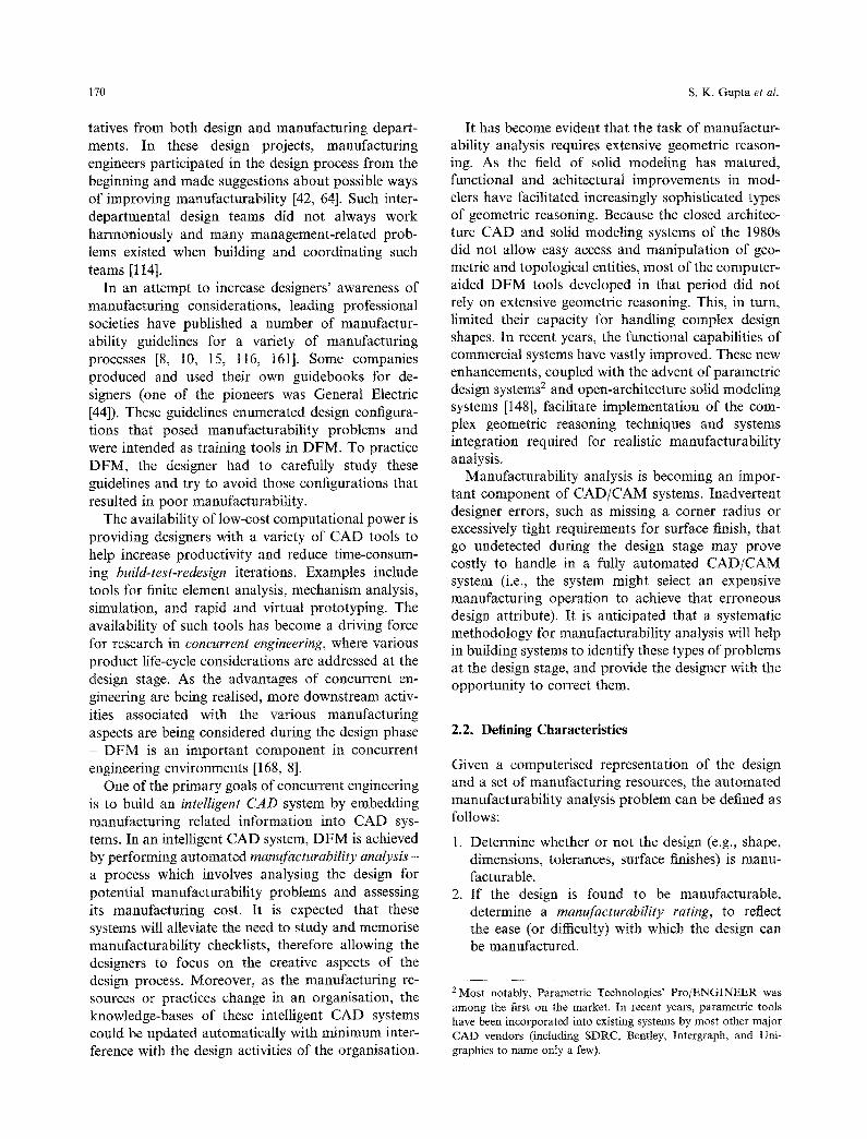
Three of the primary characteristics that distin- guish various manufacturability systems from each other include what approach they take, what measure of manufacturability they use, and what level of automation they achieve. These three characteristics are described further below:
2.2.1. Approach For analysing the manufacturability of a design, the existing approaches can be classified roughly as follows:
• In direct or rule-based approaches [69, 74, 130], rules are used to identify infeasible design attri- butes from direct inspection of the design descrip- tion. This approach is useful in domains such as near-net shape manufacturing. However, it is less suitable for machined or electro-mechanical com- ponents, in which interactions among manufactur- ing operations can make it difficult to determine the manufacturability of a design directly from the design description.
• In indirect or plan-based approaches [57, 56, 66, 51] the first step is to generate a manufacturing plan, and modify various portions of the plan in order to reduce its cost. I f there is more than one possible plan, then the most promising plan should be used for analysing manufactm'ability. These systems have wider applicability than do direct systems.
2.2.2. Measure o f Manufacturabitity There are many different scales or combinations of scales - on which manufacturability can be measured:
• Binary measures': This is the most basic kind of manufacturability rating: it simply reports whether or not a given set of design attributes is manufac- turable.
• Qualitative measures: Here designs are given quali- tative grades based on their manufacturability by a certain production process. For example, Ishii et al. [69] rated designs as 'poor', 'average', 'good', or 'excellent'. Sometimes such measures are hard to interpret - and in situations where the designer employs multiple manufacturability analysis tools (for example, one for machining and the other one for assembly), it becomes difficult to compare and combine the ratings from the two systems to obtain an overall rating.
• Abstract quantitative: This type of scheme involves rating a design by assigning numerical ratings
along some abstract scale. For example, Shankar et al. [145] proposed a scheme in which each design attribute was assigned a manufacturability index between 1 and 2. Just as with qualitative measur- ing schemes, it can be difficult to interpret such measures or to compare and combine them.
• Time and cost: In general, a design's manufactur- ability is a measure of the effort required to manufacture the part according to the design specifications. Since all manufacturing operations have measurable time and cost, these can be used as an underlying basis to form a suitable manu- facturability rating. Ratings based on time and cost can easily be combined into an overall rating. Moreover, they present a realistic view of the difficulty in manufacturing a proposed design and can be used to aid management in making make- or-buy decisions. These measures may not be directly helpful for determining if the designer has achieved a satisfactory level of manufacturability in the design. To some extent, the target production time and cost can be used by the designer to help him in designing products that meet these targets.
With the exception of binary measures, all other currently available measures can be used to compare two alternative designs. However, in most cases they are not adequate for determining if a design has achieved a satisfactory level of manufacturability. A design may be complex due to intended functionality and may require a large manufacturing effort. For example, an aircraft engine requires a large number of features to satisfy its intended functionality and therefore needs a large production time. On the other hand, a can-opener requires very few features and therefore can be produced quite easily relative to the aircraft engine.
Existing measures seem to work satisfactorily when comparing two different designs of aircraft engines or comparing two different can-openers. However, com- paring manufacturability of an aircraft engine to that of a can-opener is a different story. In order to have more meaningful measures of manufacturability, we need new measures which account for intended functionality and cost targets in measuring manu- facturing.
2.2.3. Level o f Automation This last characteristic involves how the designer interacts with the system and what type of informa- tion is provided to the designer as feedback.
• Amount and type o f designer interaction: In some systems (e.g., [75]), the designer may need to enter a feature-based representation of the design in terms

172 S.K. Gupta et at.
Defining Characteristics
Fig. 2. Defining characteristics of manufacturability analysis systems.
of the particular feature library used by the system. In more sophisticated systems, [112], the system works directly from the solid model of the design. If needed, feature-based representations are gener- ated automatically.
• Amount and type o f feedback information: Most manufacturability analysis systems provide some kind of manufacturability rating of the design. Some systems provide detailed decomposition of the manufacturability ratings of various design attributes [51]. A few systems provide, along with the manufacturability rating, redesign suggestions to improve the design. Usually these are sugges- tions to change parameters of various design features [141], but some systems [57] present re- design suggestions as complete redesigned parts.
Figure 2 graphically shows the above defined char- actersics.
2.3. Survey Overview
In this survey, we have attempted to provide an overview of representative manufacturability analysis tools and related technologies which form the under- lying basis for several components of the manufactur- ability analysis systems.
Section 3 gives an overview of representative work in manufacturability analysis for a variety of manu- facturing processes - we provide brief summaries of representative manufacturability analysis systems dis- cussed in open literature. In this section, we have attempted to illustrate various approaches, measures of manufacturability, and level of automation through existing representative systems. Currently there is no well accepted terminology to describe the scope of various existing systems. Sometimes it is not clear from reading the published literature the exact
scope of the work. To avoid any potential confusion and misrepresenting the work, we tried to use authors' terminology to convey their ideas. However, whenever enough information was available, we have tried to highlight the key keatures of systems in terms of terminology introduced in Section 2.2. We hope that future researchers will come forth with other views on the problem, other surveys, and expand on the initial step we are trying to take to better define this research area.
Previous research in a number of related technol- ogies such as functionality representation, feature recognition, automated process planning, and cost estimation has had a significant influence on research in manufacturability analysis. Currently many mann- facturability analysis systems have feature recogni- tion, process planning, and cost estimation tools as integral components of the system, Therefore, in our opinion, a survey on manufacturability analysis wilt be incomplete without addressing these related tech- nologies. Section 4 provides a summary of research in functionality analysis, feature recognition, process planning, and cost estimation as it relates to manu- facturability analysis systems.
Finally, Section 5 summarises the current state-of- the-art, outlines system performance requirements, and describes future research challenges in building commercial-strength manufacturability analysis systems.
3. Representative Manufacturability Analysis Tools
The manufacturability of a design is strongly depen- dent on the manufacturing processes used to create it. For example, a design that has an ideal shape for casting may not be suitable for machining. Hence, approaches to computer-aided manufacturability analysis are strongly influenced by the type of manu- facturing processes they select to address. Below, we describe automated manufacturability analysis sys- tems for several different types of manufacturing domains, including assembly (Section 3.1), machining (Section 3.2), printed circuit boards (Section 3.3), and other miscellaneous efforts (Section 3.4).
3.1. Assembly
Most early work on assembly analysis was rule-based: design attributes of the components, the assembly operations, and relationships between components were used to estimate the ease or difficulty of assembly of components. These rule-based
Automated Manufacturability Analysis 173
approaches represented a breakthrough over the existing state of the art. Currently, however, more plan-based evaluation systems are being developed in order to better reason about situations where the particular assembly sequence greatly affects assembl- ability.
The pioneering work of Boothroyd and Dewhurst [11] in developing the design-for-assembly guidelines has resulted in several automated assembly evalua- tion and advisory systems [74, 66]. Swift [154] also presented a methodology similar to that of Booth- royd and Dewhurst. Another effort in this direction was made by Jakiela and Papatambros [74], who developed a design advisory system by integrating a rule-based system with a CAD system. Jakiela's system provides a library of predefined features with which the designer can create a design; when new features are added to the design, the system makes use of production rules to evaluate the design and offer suggestions for improving it. In his approach, the designer creates parts using the features offered by the library, working incrementally and, as the design progresses, offering advice at every design step. Hence, the design improvement suggestions are strongly influenced by the sequence in which the designer enters various features.
De Fazio and Whitney [26, 27] presented one of the first efforts to develop possible assembly sequences and selecting suitable ones using manufacturing in- formation. They identify 'liaisons' between compo- nents of the assembly. The 'liaisons' represent connections or relations between assembly compo- nents, usually in the form of physical contacts like snaps and screws. From these liaisons, assembly precedences are identified and used to determine the feasible assembly sequences. The assembly sequences are generated from a disassembly state by adding components until a final assembly is generated. In most cases their algorithm generates multiple alter- native sequences. The determination of precedence constraints is an interactive process and their meth- odology does not obtain them directly from a solid model. The algorithm needs to be extended to extract the liaisons automatically for use in an automated assemblability evaluation system.
Although the Hitachi Assemblability System [104, 105] was not initially computerised, over time it has served as a basis for development of an automated assemblability system. The Hitachi methodology is based on the principle of one motion per part; there are symbols for each type of assembly operation and penalties for each operation based on its difficulty. Finally, the method computes an assembly evaluation score and an assembly-cost ratio. This assembly-cost
ratio gives an indication of cost per operation. By studying these results one can identify the sources of bad assemblability and, after modifications to the designs are made, these metrics can be recomputed to find the degree of improvement. The methodology is common for manual, automatic and robotic sys- tems. One of the early success stories of this method is highlighted in [55].
Warnecke and Bassler [166] studied both functional and assembly characteristics. Parts with low func- tional value but high assembly difficulty receive low scores, while parts with high functionality and low assembly cost receive high scores. The scoring is used to guide the redesign process.
Miles and Swift [100] developed an assembly evaluation method in which parts are divided into two groups based on functional importance: 'category A' parts are required from the design specification, and 'category B' parts are accessories. The goal of the method is to eliminate as many 'category B' parts as possible through redesign. Analyses of feeding and fitting are carried out on the parts, with both results combined into a total score. This total is divided by the number of 'category A' parts in order to calculate a final score. A proposed assembly sequence is used to perform fitting analysis.
Sturges and Kitani [150] have developed a semi- automated assembly evaluation methodology that attempts to overcome some of the limitations of the scheme proposed by Boothroyd and Dewhurst [11]. Currently, while lacking geometric reasoning capabil- ities, their system serves as an interactive environment to study the effect of various design configurations on assembly difficulty.
Li and Hwang [93] did a study of design for assembly and developed a semi-automated system which closely follows the Boothroyd-Dewhurst methodology. The analysis of assembly difficulty and cost estimation modules is a direct computer implementation of the DFA rules. Their methodol- ogy considers multiple assembly sequences and calcu- lates the time for all of the feasible sequences. They perform limited feature recognition for assembly and obtain from the user the non-geometric information that will affect the assembly. The final result is a table which is roughly the same as a manual assembly worksheet. The authors argue that the assembly information developed quickly and in proper format will give the designer enough input to perform further analysis for design modification. The task of auto- mated redesign is presented as a future goal.
Hsu et al. [66] developed an approach to design- for-assembly that examines and evaluates assembly plans using three criteria: parallelism, assemblability,

174 S.K. Gupta et al.
and redundancy. They evaluate assembly plans in an attempt to find problems with the assembly and, when possible, introduce modifications to improve the plan. If a better plan is found, the design is modified by splitting, combining or perturbing vari- ous components. This system is one of the first approaches in plan based assemblability evaluation and redesign suggestion generation for assembly. There are limitations of this approach and compared to the work of Boothroyd and Dewhurst [11] their assemblability evaluation criteria are restricted. They do not consider tolerance and surface finish issues and can only suggest minor modifications to design. Also, in the absence of any model of the functional requirements of the product, the modified design may not satisfy the designer's intent.
Recent work by Jared et al. [77] presented mathe- matical models for the assembly operations and a DFA system that performs geometric reasoning based on the model. In this way, they rely less on user input. Their system calculates a manufacturabil- ity index for individual components and fitting index between the components.
Boothroyd [12] presents a view of design for manufacture and assembly methodologies in use at different companies.
3.2. Machining
Initially, the efforts in machining sought to relate the different attributes of a part design to the manufac- turing process so that design rules could be employed to assess manufacturability. Because of the very nature of the machining process, different operations almost always interact with each other; and because of these interactions it becomes very difficult to isolate in- stances to apply these rules. An additional complica- tion is due to the fact that there usually exists more than one way of manufacturing the same part. In these cases it comes nearly impossible to identify manufacturing problems with design rules alone. Currently the trend is towards plan-based systems. Earlier methods, with abstract rating schemes, are also yielding to more direct measures like time and cost. Due to the different kinds of variables involved in the maching process, this remains the most chal- lenging domain.
Subramanyan and Lu [151] developed a manufac- turability evaluation system for bearing cages. They addressed several aspects of the manufacturability problem including fixturing, tooling, gauging, and materials handling. They used a multiple cooperative knowledge sources paradigm that separated domain knowledge from the control procedure. Their domain
was restricted to parts with axi-symmetric features which can be manufactured on a lathe.
Priest and Sanchez [124, 138] developed an empiri- cal method for measuring the manufacturability of machined parts. Their approach involves rating a design based on producibility rating factors. The producibility rating factor is calculated from consid- erations that influence producibility and observed production difficulties. They defined producibility rating factors for a variety of manufacturing considerations such as material availability, machin- ability tooling, material/process risk compatibility, etc.
Hsiao [65] developed a knowledge-base for per- forming manufacturability analysis of machined parts. His approach is capable of incorporating user-defined features and represents machining pro- cesses by their elementary machining volumes and limitations on tool motion. For each design feature, he defined constraint- face sets that represent various machining faces and any neighbouring faces that restrict the accessibility of the feature. Constraint- face sets are evaluated to determine if the feature can satisfy the conditions imposed by the elementary machinable volume and tool motion for the machin- ing process. While their approach is capable of handling a limited number of accessibility constraints and tolerances, it does not consider the possibility of alternative features and does not provide any manu- facturability rating scheme.
Anjanappa et al. [7, 84] developed a rapid proto- typing system for machined parts that emphasised existing standards and available databases. The de- sign is stored as an IGES file and a rule-based feature extractor is used to find machining features. The feature extractor is limited and no intersections among features are allowed. The manufacturability analyser performs analysis based on the specific machining cell configuration for which the system was designed. The manufacturability rating does not calculate machining cost and time but it does match the features with tools, machines, and fixtures. In addition, it fists those features that are non- manufacturable and those that are potentially difficult to manufacture. From these features, it also creates the NC machining code to machine the component. This system does not investigate the possible alternative ways of machining the same part.
Hitachi corporation [103] extended their design for assembly methodology to also take into account machining processes. Together with their AEM method, this results in an overall producibility eva- luation system. Boothroyd and Radovanovic [13] published a report on the evaluation of machining

Automated Manufacturability Analysis 175
components during the early design stage. They described two methodologies for arriving at cost estimates. The first methodology takes into account only part and stock geometry, batch size, material and component type. The second methodology uses more shop floor information. In both cases, the feedback is in terms of manufacturing cost.
Cutkosky and Tenenbaum [24] developed NEXT- Cut: a system for the design and manufacture of machined parts. Using NEXT-Cut, the designer can create a design by subtracting volumetric machining features corresponding to machining operations from a piece of stock material. As features are subtracted from the workpiece, the system uses its knowledge- base to analyse the design's manufacturability. If any of a variety of manufacturability constraints are violated, the designer is warned of the violating features. This system works directly with features defined by the designer and so it is incumbent upon the designer to describe the design in terms of the most appropriate set of features. NEXT-Cut requires that the designer has good knowledge about machin- ing processes in order to select the most appropriate feature set for machining; failure to do so may produce incorrect analysis.
Yannoulakis et al. [175, 176] developed a manu- facturability evaluation system for axi-symmetric parts machined on turning centres. They created a feature-based description of the part and evaluated the manufacturability index of each feature. The manufacturability index was based on the estimated machining time of the feature; calculated with empir- cal techniques for estimating cutting parameters and machining time. Their method did not consider geometric tolerances or the possibility of alternative features. The final result from the manufacturability evaluation procedures employed by them is a set of different indices, each providing a different indicator about the manufacturability of the individual features and the complete overall part. Some of these indica- tors deal with the time spent in loading-unloading, fixturing and changing tools. One feature of their system is that it ranks the features as candidates for redesign based on the analysis results. A number of research issues such as feature accessibility, prece- dence constraints, setups, etc., need to be addressed in order to scale up their approach to prismatic parts.
Gupta et al. [47, 51] describe a methodology for early evaluation of manufacturability for prismatic machining components. Their methodology identifies all machining operations which can be used to create a given design. Using those operations, different operation plans for machining the parts are gener- ated. For each new operation plan generated, it is
examined whether the plan can produce the desired shape and tolerances. If the plan is capable of doing so, the manufacturability rating from the plan is calculated. If no operation plan can be found that is capable of producing the design, then the given design is considered unmachinable; otherwise, the manu- facturabitity rating for the design is the rating of the best operation plan. The rating is based on estimated machining time for the part. Based on this approach, Das et al. [25] reported a methodology of suggesting improvements to a given design to reduce the number of setups to machine a part. Their approach involved using different machining operations to satisfy the geometric constraints put on the part by the designer. These constraints are based on the functionality of the part. Later, different modifications are combined to arrive at redesign suggestions.
There are many other research efforts in manufac- turability analysis for machining. We briefly mention two others: Philip Chen and LeClair [120] have developed a system for setup generation and feature sequencing. They use multiple objective functions for setup and tool sequence generation. Mill et al. [101] devised a simultaneous engineering workstation.
3.3. Printed Circuit Boards
The role of the designer in the design of printed circuit board (PCB) components is broader than in other domains. Usually the designer, based on what is commercially available, selects components; this se- lection in turn dictates the production method. Hence, printed circuit boards and their process plans are developed simultaneously. While ideal systems for manufacturability analysis are plan-based, rules are often better suited for certain sub-problems within this domain.
Similar to design for assembly, many major electronic manufacturers have taken the lead in developing metrics for evaluation of printed circuit board designs. NEC corporation [1], General Electric [146] and Xerox [174] have reported in-house systems for evaluating PCB designs and assemblies.
O'Grady et al. [114] developed a constraint-based system (LARRY) that addresses various life-cycle considerations during the design of printed wiring boards. They treat the design process as a constraint satisfaction problem where the various manufactur- ability considerations are represented as a constraint network. As the designer adds features to the design, the constraint network is evaluated for possible violations. If violations are found, the designer can either select different manufacturing resources or modify the feature that caused the violation. Their

176 S. K, Gupta et al.
approach is computationalty intensive: as more fea- tures are added to the design, the constraint network grows in size. Their system considers only drilling of holes on printed wiring boards and it is not clear how their approach will handle the computational prob- lems posed by consideration of additional manufac- turing operations.
Harhalakis et al. [54] developed a system for manufacturability evaluation of microwave modules. Their system works with a STEP form feature based representation of the design, and uses rough-cut process plans to assign a manufacturability rating on a scale from 1 to 10. This rating system was developed by interviewing the machinists on the shop floor and, while reflecting difficulty associated with manufacturing, there is no direct correspondence between the ratings and manufacturing cost or time. Their system has a limited capability to perform geometric reasoning to identify interacting features but the effects of precedence constraints, tool changes, setup costs, etc., are not considered in their evaluation criteria.
Other works in manufacturability analysis of PCBs include Refs [131, 115, 149, 9]. These efforts are for the most part for specific sub-domains of PCB manufacturing. Most are rule-based and, because of the fast pace of technological changes, these rule- bases need to be updated regularly. The majority of the state-of-the-art research in this area is happening within the manufacturing industry's research and development centres.
3.4. Miscellaneous Manufacturing Processes
Various near-net shape processes (e.g., casting, stamping, injection moulding, sheet metal working) often have specific manufacturing defects associated with them. Rules are used to associate design attri- butes with the probability of a defect. Production occurs in two steps: first, the production engineer accounts for the manufacturability of the tooling; and second, assesses the manufacturability of the actual part. Near-net shape processes create parts in a manner that is particularly well suited for the use of rules to encode the relationships between design attributes to manufacturing processes. Rule-based systems have found success in near-net manufactur- ing domains and the recent trend is toward using knowledge of process physics and simulation to reason about manufacturability, looking for viola- tions of design-for-manufacturability heuristics.
Ishii et al. [69, 2, 71, 72] have developed design- compatibility analysis tools to aid in designing prod- ucts for various life-cycle considerations. In their
approach, a set of design elements is defined for each life-cycle application. While the designer interactively identifies these elements in a proposed design, she is prompted to provide information about user and functional requirements. Their system uses a compat- ibility knowledge-base to evaluate tradeoffs between various design elements and functional requirements. A compatibility knowledge-base is a collection of domain-dependent rules used to calculate a compat- ibility index. If a design attribute receives a poor compatibility index, the system offers advice by illustrating predefined cases that result in good com- patibility. Ishii and his colleagues have built a number of design advisory systems using this approach.
E1-Gizawy et al. [38] presented a system which considers the suitability of different manufacturing processes for a given part based on a process cap- ability database. Once a process is chosen, two types of analysis are performed: first a rule-based analysis using knowledge- and rule-bases, at which stage rede- sign suggestions are provided. These suggestions are not for the complete parts, but for portions of the design. Secondly, an analytical and experimental process simulation is performed to determine the time required to produce the part and its material require- ments. The methodology also includes in its cost calculation the machining cost after a net shape process.
The work of Huh and Kim [67] describes a system for supporting concurrent design for injection mold- ing. Their interactive expert system encodes rules for different moulding materials and supports the syn- thesis of supplementary features to be put on to the initial design. The system aids the designer when performing tasks such as the determination of rib requirements, rib cross-sections, rib frequency and design of bosses. Both function and manufacturabil- ity are considered when providing help for these decisions. Interactive feedback is provided to the designer in two forms: first the probability of having different forms of manufacturing defects, such as sink marks, warpage, or ejection difficulty. The second type of feedback is in the form of a warning message which suggests possible problems for the designer to avoid. The feedback is quantitative, giving the prob- ability of occurrence of the manufacturing defects. This information is hard coded in the rules and the numbers that are calculated can only reflect the cases considered by the system.
Wozny et al. [171-173] have developed a unified representation to support evaluation of design for manufacturability. Their approach is broad and more complete than most others and considers multiple manufacturing processes when evaluating compo-
Automated Manufacturability Analysis 177
nents. Evaluation is done hierarchically during the configuration and detailed design stages. In addition, they consider the functionality of the parts, tolerance information, and also provide redesign suggestions. Finally, they also consider assembly of the compo- nents. Their approach integrates many phases of the design and manufacturing process.
Bourne [14] reports work at Carnegie Mellon University towards an 'Intelligent Bending Work- station'. Being developed in the same line as CMU's earlier Intelligent Machining Workstation project, they are implementing an open architecture model for a bending controller in order to overcome the common difficulties posed by closed NC machine controllers. This system will be customisable and extendable, allowing for future incorporation of additional modules.
Nnaji et al. [113] reported development of a com- plete product modeller for concurrent engineering. This modelling system builds a product model with assembly, dimensioning and functionality considera- tions. It follows a set of part-to-part relations defined for assembly operations based on standard spatial relationships. The modeller also does manufactur- ability analysis for sheet-metal work and assembly. These analyses are based on production rules and collision relations, they do not include consideration of functionality.
Dissinger and Magrab [33] have developed a three- dimensional modelling system for designing powder metallurgy components. The part design is created layer by layer and, with the addition of each layer or a component to a layer, checks are made for possible manufacturing rule violations. The system is inter- active, alerting the designer of the rule violations and giving suggestions for modifications. Finally, the system allows only the design of manufacturable components.
Subramaniam and Ulrich [152] proposed a method for developing producibility metrics for process- physics dominated production processes such as extrusion, injection moulding, etc. Their approach predicts the likelihood of common manufacturing defects based on different physical characteristics of the design. As an example, they developed metrics for various types of defects in extruded aluminium components for aircraft. In this work, they conducted experimental and statistical verification of the metrics based on actual vendor data.
Shah and Rogers [143] present two different domains of manufacturability evaluation. The first system involves machining [144], where alternative machining operations are evaluated and suitable ones chosen. Initially setup or sequencing issues
are not considered. After selecting operations, two types of checks are performed: first, rule-based check- ing to find if there are violations of 'good practice'. During the second check, the cheapest possible feasible sequence of operations is found using a branch and bound search technique and redesign suggestions are also presented. The feedback results are in terms of machining cost. Their second system involves forming methods of fibre-reinforced thermo- plastics. It is a rule-based system which considers both the part manufacturing and the tooling. It also suggests redesigns in terms of parameters of the design features.
The Toshiba Corporation [156] is using a pro- cessability evaluation method which works in tandem with an assemblability evaluation method. The cost of any part depends on the processing method with a rating calculated by examination of alternative processing methods. Cost is determined by using a combination of different processes and materials.
There are additional works reported by researchers on various types of net shape manufacturing, includ- ing injection moulding [29, 41, 68, 125, 130, 45], die casting [30], sheet metal work [155, 178, 29], casting [941, powder metallurgy [87], extrusion [63], and stamping [951.
Shankar and Jansson [145] proposed a domain independent methodology to evaluate the manufac- turability of designs based on a set of five core manufacturability concepts: compatibility, complex- ity, quality, efficiency, and coupling. Based on each of these concepts, they assign a manufacturability index to various attributes of the design. The overall manufacturability of the design is characterised by the sum of the indices for every attribute of the design. While this methodology addresses some of the manufacturability issues, it considers no specific manufacturing process - thus, it cannot determine whether a given design is manufacturable or not. In addition, their approach does not identify the design attributes that pose manufacturability problems.
4. Related Technologies
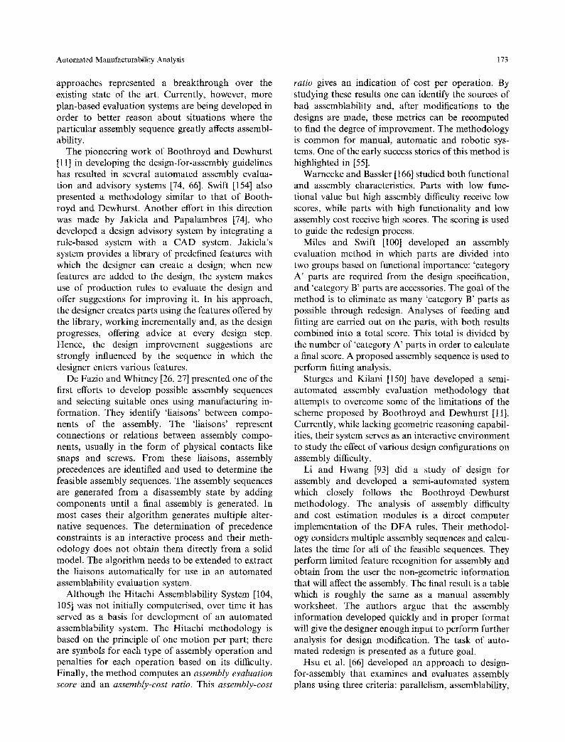
Previous research in process planning systems has significantly influenced the development of manufac- turability analysis systems. As shown in Fig. 3, several core process planning components (such as generative planners, feature recognisers, etc.) are used in manufacturabitity analysis systems. In this section, we briefly review related technologies which have had

178 S, K. Gupta et at.
Design and Manufacturing Integration First Generation
determine how to manufacture efficiently
process planning
/ Process Planning Components
Design and Manufacturing Integration Second Generation
determine how to improve manufacturability
@ manufacturability ~ analysis
CoInlTlon
Components Manufacturability Analysis
Components
Fig. 3. Relationship between manufacturability analysis and process planning.
either a significant influence on manufacturability analysis systems, or provide critical inputs for such systems. All of the four related technologies covered in this section are well established research areas and have many other applications besides manufactur- ability analysis.
In order to offer meaningful suggestions for design changes to improve its manufacturability, the manu- facturability analysis system needs to have some notion of intended functionality of the design. Section 4.1 reviews some leading works in functionality representation. Most manufacturability analysis sys- tems use feature-based representation of the design. Quite often, feature extraction systems are used to generate feature-based representations. Section 4.2 presents some discussion on the current research in feature-based design interpretations. In case of ma- chining process, techniques very similar to that of generative process planning are used to perform manufacturability analysis. Section 4.3 gives an outline of research in generative process planning and related areas. Many manufacturability analysis systems rate designs in terms of manufacturing costs. Section 4.4 reviews various cost and time estimation techniques.
4.1. Functionality Representation
Manufacturability evaluation goes hand in hand with product redesign. This redesign process can be auto- matic, interactive or manual. In all such cases it is necessary to have a model of what the component under consideration is meant to accomplish. For this
reason, we expect future manufacturability evalua- tion systems to provide for some degree of function- ality representation.
We present a brief introduction on how the func- tionality of a part can be represented in its CAD model. In most cases, the goal of research efforts on functionality representation has been the develop- ment of the representation itself; often the scope of the representation is very broad. In other efforts, the goals were specific to a class of products where the design attributes and functionality are intimately coupled. Nielsen et al. [111] reported a system for iterative design where functionality is represented as the target values for different parameters. Thompson and Lu [158] proposed a methodology for repre- senting design rationale. Their design rationale in- cluded plans constructed for planning future products and design constraints identified during the design process.
Dighe et al. [31, 32] developed a system for a specific range of products (injection moulded product housing) where the basic functions are mounting and structural rigidity. Welch and Dixon [167] developed a system for sheet metal bracket design. The only functionality required in this domain was the load path - a task they successfully accomplished. Schie- beler and Ehrtenspiel [140] described a knowledge- based design assistant. This system represented func- tionality as a graph where the features are the nodes. The edges between the features depend on functional relationship between the features.
E1 Maraghy et al. [39] proposed and implemented a design scheme based on functional features. The
Automated Manufacturability Analysis 179
functions are pre-defined into the features in the library. Such functional features are also the core of the work of Schulte et al. [142].
Henderson et al. [59, 60, 157] developed a system for conceptual modeling and representation of func- tionality, features, dimensions, and tolerances within a solid modeling system. Their functionality repre- sentation is based on textual descriptions that anno- tate the geometric model. This representation cannot directly be used for automated redesign purposes, as it does not lend itself to geometric queries and design modifications. The model described is detailed and may serve as a valuable guide for future development of functional models for other purposes.
Sodhi and Turner [147] argue that effective func- tionality representation can only be achieved at the assembly level of a product. They present a state of the art survey of assembly modeling research which demonstrates some functional modeling. Gui and M~intylfi [46] proposed a bond graph-based system of assembly modeling from a functional perspective.
There are other research works related to function- ality, design history, and design rationale representa- tion, many of which are worth noting [6, 17, 19, 83, 85, 91, 139]. Detailed presentation of this body of work is beyond the scope of this paper.
4.2. Feature-Based Design Interpretation
In order to perform manufacturability analysis, a product design must be interpreted in terms of manufacturing features. Automated .feature recogni- tion has become the preferred technique for produ- cing such feature-based representations, having been successfully employed for a variety of applications including process planning and part code generation for group technology. These feature technologies rely heavily on the geometric and topological manipula- tion capabilities of solid modeling systems and deal predominantly with form or machining features.
Kyprianou [89] presented the first effort to use a combination of graph algorithms and grammars to parse solid models of parts for group coding. Kramer [88] has presented a grammar-based method for extracting non-intersecting features for a class of 2.5-dimensional parts. Methods based on graph- grammars have been used to both recognise features [121, 134] and translate between differing feature representations [129]. Peters [118] analyses the com- binatorial complexity of graph and grammatical approaches to feature recognition and presents heur- istics to reduce these costs. In another effort to address combinatorial problems and handle realistic
industrial designs, Gadh and Prinz [40] describe techniques for abstracting an approximation of the geometric and topological information in a solid model and finding features in the approximation. More recently, Regli et al. [128] have outlined meth- ods to utilise multiple distributed processors. Their initial results show that multi-processor techniques can be effectively employed to expand the class of mechanical designs that are feasible and produce improvements in system response times.
Woo [170], in an early effort on feature extraction, proposed a method for finding general depression and protrusion features on a part through decomposing the convex hull of the solid model. The approach had several limitations, including the existence of patho- logical geometric cases in which the procedure would not converge. The non-convergence of Woo's ap- proach has been solved in recent work by Kim [81, 82, 164], whose system produces a decomposition of the convex hull of a part as general form features. Extension of this method from polyhedra to the more general surfaces required for realistic parts is cur- rently under investigation [99].
Other volume decomposition approaches include the recent work by Sakurai and Chin [137]. Exhaus- tively, each combination of cells is matched against user-defined feature templates. While the method is capable of generating all alternative feature inter- pretations composed of the primitive cells, it does so at a large combinatorial cost.
The seminal work of Henderson [58] employed rule-based systems on the feature recognition prob- lem and has served as a foundation for more recent AI-based approaches. Henderson has also made extensive use of graph-based methodologies, first [43] where graph-based algorithms are used to find protrusion and depression features. Chuang and Henderson [20] use graph-based pattern matching to find feature patterns from part geometry and topology. Chuang and Henderson [21] were the first to explicitly address both computational complexity and decidability when defining the feature recognition problem. Their paper formalised the problem of recognition of features (including compound features) through parsing a graph-based representa- tion of a part using a web grammar. Most recently, Prabhakar and Henderson [123] adapted neural net- works to recognise features from polyhedral objects. Also in this area, Peters [117] describes techniques for training neural networks to recognise feature classes that can be customised by the end user. In a recent paper, Henderson et al. [61] survey a variety of feature recognition methodologies.
180 S.K. Gupta et al.
Other graph-based methodologies include the work of De Floriani [28], who employed graph-based algorithms for finding bi-connected and tri-connected components to partition a polyhedral part into several varieties of protrusion and depression fea- tures. Joshi and Chang's [79] approach used subgraph isomorphism algorithms to match feature patterns to patterns in the topology of polyhedral parts. Sakurai and Gossard [136] developed a graph-based system capable of handling limited types of user-defined features, providing for a degree of application-specific customisability. Corney and Clark [22, 23] have had success extending the capabilities of graph-based algorithms to more general 2.5-dimensional parts. The work of Dong and Wozny [34~36] included formalisation of a feature description language and was the first to employ a frame-based reasoning system to extract machining features for computer- aided process planning. Their approach included the ability to construct volumetric features from surface features and perform an analysis of tool accessibility.
Karinthi and Nau [80] presented the first systematic work on the generation of alternative interpretations of the same object as different collections of volu- metric features. They present an algebra for comput- ing alternate interpretations of parts resulting from algebraic operations on the features.
The ability to recognise interacting features has been a goal of a number of numerous research efforts, among them [40, 79, 34]. The approach of Marefat and Kashyap [96, 97] built on the representation scheme of Joshi and Chang [79] and used a combina- tion of expert system and hypothesis testing tech- niques to extract surface features from polyhedral objects and handle a variety of their geometric interactions. Marefat argues that his approach is complete over a class of polyhedral features, i.e., that it generates all features in his class that can be found from the geometry of a part. Another recent ap- proach [160] addresses completeness over a limited domain of iso-oriented polygonal parts. Regli et al. [126, 127] present a methodology for specifying the feature recognition problem and proving it is com- plete over a well-defined class of parts. Their features are based on a class of machining features that describe operations on three-axis machining centres and encompass a realistic class of parts bounded by analytic surfaces.
The most comprehensive approach to data for recognising features and handling their interactions has been the OOFF system (object-oriented feature finder) of Vandenbrande and Requicha [163]. Van- denbrande's work, using a knowledge-based ap- proach like that of Dong and Wozny, provides a
framework for recognising machining features and building process plans via artificial intelligence techniques in combination with queries to a solid modeller.
Work of Laakko and Mgntylfi [90] couples feature- based design and feature recognition to provide for incremental feature recognition. This type of ap- proach identifies changes in the geometric model as new or modified features while preserving the existing feature information. They also provide for some form of customisability with use of a feature-definition language to add new features into the system.
Other related work includes feature recognition from 2D engineering drawings [98], feature recogni- tion tbr sheet metal components [92], and feature modeling by incremental recognition [90]. Many aspects of the feature recognition problem are still open and active areas of research. Among these are: recognising and representing interacting features [163], incremental recognition of features [52], mod- elling alternative feature interpretations [96, 127], reasoning about the manufacturability of features [51, 47], and incorporation of user-cnstomisable feature classes.
4.3. Generative Process Planning
As mentioned in previous sections, many of the manufacturability evaluation systems use manu- facturing plans to evaluate manufacturability. For this reason we include here a brief review of some representative systems of automated process plan- ning.
Computer-aided process planning is a key element in integrating design and manufacturing [5]. Many attempts have been made to automate process plan- ning of machined parts [24, 5, 16, 18, 106, 50, 165]. The two traditional types of approach to computer- aided process planning are the variant approach and generative approach. The variant approach involves retrieving an existing plan for a similar part and making the necessary modifications to the plan for the new part. The generative approach involves generation of new process plans by means of decision logics and process knowledge. Most plan-based manufacturability analysis systems use generative techniques. Therefore, we will only discuss the gen- erative approach in this paper.
Usually, the task of generative process planning involves a number of inter-dependent activities, most of which cannot be performed independently. Gen- eration of the optimal process plan usually requires several iterations and, although significant progress has been made, at present there are no automated

Automated Manufacturability Analysis 181
process planning systems capable of automatically performing the complete planning task. This section only deals with those steps that are relevant to manufacturability analysis. For details and a litera- ture survey on the complete plan generation steps, readers are referred to [5, 18, 165].
4.3.1. Process Selection Process knowledge involves the shape producing capability and technological constraints for each of the available machining processes. A variety of knowledge representation techniques are used to model process knowledge, with production rules and frames among the most popular. Production rules involve condition-action sets, and are often expressed in the form of IF-THEN rules. Examples of systems using production rules include XCUT [16] and AMPS [18]. Frames can represent both procedural and declarative information in terms of attributes, hierarchical relations with other frames, constraints, and procedures. SIPS [106] and NEXT-Cut [24] use frames to represent process knowledge.
The process selection task is performed by examin- ing the shape and tolerance requirements of an individual feature and selecting a process that is capable of meeting the requirements. Quite often, a feature needs a roughing operation followed by one or more finishing operations. Backward planning strategies have been successfully used to select the multiple operations needed for certain features. A number of process planning systems, among them AMPS [18], SIPS [106], use this technique to perform process selection.
4.3.2. Identifying Precedence Constraints For a given part, the machining operations cannot be necessarily performed in any arbitrary order [48]. Geometric and technological constraints will require that certain operations be performed before or after other operations.
AMPS [18] uses heuristic techniques to determine precedence constraints among features. A number of rules based on machining practices have been defined and are used to determine precedence constraints among pairs of features. This approach allows for strict and loose constraints. Strict constraints cannot be violated, while loose constraints can - but at a detriment to ensuring good machining practice. The features in this approach are allowed to have multiple approach directions and may require conditional precedence constraints.
The machinist system [62] is capable of handling the precedences that arise because of setup considera-
tions. In this system, precedences are generated by examining the setup interactions among features. If the machining of a feature destroys the precondition for clamping during machining of another feature, then these two features interact and a precedence constraint exists.
Because of its closeness to well-known combinator- ial optimisation problems, optimisation of operation sequences has received significant research attention. A number of systems have been developed that take precedence constraints as input and find the optimum operation sequence [120, 122]. However, most of these systems do not automatically generate the complete set of precedence constraints.
Precedence constraints are also important in gen- erating and evaluating alternative assembly se- quences. De Fazio and Whitney [26, 110] provide some examples of that.
4.3.3. Fixturability and Setup Planning To ensure successful machining, each intermediate workpiece shape should be fixturable. This requires consideration of fixturing devices and formulating the conditions that are needed to insure proper fixturing. Setup planning involves determining the various setups in which the part will be machined. While advances have been made in automated fixture design [135], existing research has mainly focused on design- ing new fixtures for a given geometry.
Chang [18] present comprehensive conditions for holding the workpiece in a vise. These conditions are based on the intermediate workpiece geometry and are sufficient for successfully clamping the workpiece. He also presented an algorithm for setup planning that, while producing valid results, in certain cases may generate setup plans that are non-optimal.
Yue and Murray [177] presented a comprehensive set of fixturability and clamping conditions for vise clamping, machine table clamping, and frame bolting for manufacture of 2.5D prismatic parts. These conditions are based on intermediate workpiece ge- ometry and consider friction forces.
For a review of fixture design automation, readers are referred to Refs [53, 159].
4.3.4. Plan Evaluation Plan evaluation consists of two main steps - verifica- tion and rating. Plan verification involves determin- ing whether or not a plan is capable of meeting the design specifications. The main research issue in plan verification is determining the achievable manufactur- ing accuracy and comparing it with the design tolerances and surface finishes. Plan rating involves

182 S.K. Gupta et al,
assigning a merit to the plan. If alternative plans exist, ratings are used to select the best plan.
Economics plays an important role in manu- facturing planning. Estimation of cost and time has been an integral part of process planning activities [18] and extensive research in machining economics has produced quantitative models for evaluating times and costs related to machining operations [169]. Various optimisation techniques have been applied to these quantitative models to determine the machining parameters which minimise the vari- able cost, or maximise the production rate and profit rate [3, 4, 37, 182].
Each machining operation creates a feature which has certain geometric variations compared to its nominal geometry. Designers normally give design tolerance specifications on the nominal geometry to specify how large these variations are allowed to be. One needs to estimate accuracy of various manu- facturing processes in order to verify whether or not a given process plan will produce the desired design tolerances.
In machining, various factors such as deformation of the workpiece and tool, vibration, thermal defor- mation, inaccuracies of machine tool, etc., affect the machining accuracy. Some of these factors are de- pendent on the selection of cutting parameters. For a limited number of machining processes, deterministic models have been developed to provide quantitative mappings between the cutting parameters (such as cutting speed, feed, and depth of cut) and machining accuracy (such as surface finish and dimensional accuracy) [165, 108, 180, 181].
Zhang et al. [180, 181, 107, 179] presented a comprehensive method for predicting the machining accuracy of turning and boring operations. Their methodology can be extended to model other machin- ing processes involving single-point cutting tools. In complex machining operations, developing mathema- tical models is a very difficult task. In such cases, empirical methods are often used. Kline et al. [86] proposed a system for predicting machining accuracy in end milling. Based on the past experiences of metal cutting industries, a significant amount of data has been published that describes the achievable machining accuracy of various machining processes [15, 161, 181.
A tolerance chart is a tool for assessing machining accuracy. It is a graphical representation of the process sequence which helps to visualise the influ- ence of the proposed sequence on resulting dimen- sions and tolerances. For each step of the operation sequence, machining accuracy is estimated and toler- ance stack-ups are calculated. Automated tolerance
charting has not been incorporated into most auto- mated process planning systems. Recently, attempts have been made to automate tolerance charting [78, 102]. Current research on computer-aided tolerance charting focuses on calculation of optimum inter- mediate tolerances typically using linear program- ming techniques.
In near net shape processes and electro-mechanical component assemblies, the process physics often determines the accuracy and quality of the parts. Subramaniam and Ulrich [152] provide some meth- ods for determining possible manufacturing defects in aluminum extrusion. Similar works are also reported in other manufacturing processes.
4.4. Manufacturing Cost and Time Estimation
A number of manufacturability analysis systems use manufacturing costs and times as the measures of manufacturability, and research in these areas has had a strong influence on the capabilities of existing systems. A significant amount of research has been done in this area and resulted in the emergence of two primary approaches to cost estimation.
In the first approach, manufacturing cost (and time) is estimated from a detailed process plan. In this type of approach, first a detailed process plan is created (either by a human process planner or by an automated system). Then, various resources and activities in the process plans are assigned costs based on either time and cost standards or using customised cost data. Manufacturing cost for a product is simply estimated by adding costs for various resources and activities in the process plan. Manufacturing time is estimated in a very similar manner by adding manu- facturing times associated with various activities in the process plan.
In the second approach, manufacturing cost is estimated without explicitly generating process plans. In this approach, a new part is analysed and com- pared to previous parts for which cost and time estimates are available. The key step in this approach is to perform similarity analysis and find similar parts for which time and cost estimates are known. In many old systems, this step was accomplished by generating group technology (GT) codes. Cost of a new part is estimated from costs of similar pre- viously produced parts. Currently, researchers are exploring use of case-based reasoning to identify similar parts.
A good review for cost estimation techniques can be found in [169, 18].

Automated Manufacturability Analysis 183
5. Discussion
5.1. Performance Requirements
Today's market-place is characterised by increasing global competition, shrinking product lifetimes, and increasing product complexity. Industries need to be able to quickly develop new and modified products, and to manufacture products at the right quality, at competitive costs (including environmental- protection-related costs as well as the usual produc- tion costs). This makes the design task more challen- ging, as designers must acquire and process a wide variety of design information and still meet ever- tightening deadlines. To assist designers with this expanded role, manufacturability analysis systems will need to be improved to meet the following performance criteria:
• Scope: As manufacturing industries adopt newer processes and materials, and participate in more collaborative manufacturing with suppliers and customers, the scope of manufacturability analysis systems will need to be expanded to take into account a variety of manufacturing issues that they do not currently address.
• Accuracy: If the analyses produced by a manufac- turability analysis system are not sound, this can result in considerable delays and/or financial losses. For example, Petroski [119] describes several cases in which design failures occurred because of errors made by software for analysing design performance.
• Speed: Since design is an interactive process, speed is a critical factor in systems that enable designers to explore and experiment with alternative ideas during the design phase. Achieving interactivity requires an increasingly sophisticated allocation of computational resources in order to perform realistic design analyses and generate feedback in real time [128].
5.2. Future Research Challenges
With the above defined performance requirements in mind, we present some specific issues that are im- portant for future manufacturability analysis systems to address:
1. Ability to Handle Multiple Processes: Many prod- ucts are produced using a combination of different kinds of processes. For example, engine blocks are first cast, and then machined to final shape. Systems are being developed that handle more
than one kind of manufacturing process [69, 113, 143]. However, manufacturability requirements for different processes are often in conflict. For example, a design shape that is easy to cast may pose problems when fixturing it for machining. It will be necessary to develop ways to handle such conflicts.
2. Alternative Manufacturing Plans: In many cases it is possible to manufacture a part using different manufacturing processes or combination of pro- cesses. Thus to accurately determine the manufac- turabitity of a product, it may be necessary to consider alternative ways of manufacturing it. In certain cases, there might be a large number of alternatives, making it infeasible to consider all of them. In order to preserve computational effi- ciency in such cases, methods are needed to discard unpromising alternatives while still produ- cing correct results. Gupta and Nau [51] provide an approach to this problem in the context of machined parts - but methods still need to be developed for other manufacturing domains.
3. Virtual Enterprises and Distributed Manufacturing: Manufacturing industries are relying increasingly on distributed manufacturing enterprises organ- ised around multi-enterprise partnerships. In such environments, manufacturability analysis cannot be done accurately without taking into account the capabilities of the various partners that one might potentially use in order to manufacture the prod- uct. Projects are underway to address this problem (e.g., [109]), but the work in this area is still largely in its early stages. Process Models and Virtual Manufacturing: A static knowledge-base of manufacturing process capabilities may not be suitable for determining the manufacturability of a product in cases where the manufacturing processes are very complicated (such as near-net shape processes), or where the manufacturing technology is changing at a fast pace (such as composites processing). Projects such as [152, 38] address this problem by analysing manufacturability using data obtained from pro- cess models and manufacturing simulations. Some of the problems remaining to be solved include the development of better and up-to-date process
models, and better integration of process models with manufacturability evaluation methods.
5. Manufacturability Rating Schemes: Fast decision- making regarding the manufacturability of pro- posed designs is becoming more important than ever. For helping designers and managers to make engineering and financial decisions, ratings of a qualitative or abstract nature will not be
.

184 S.K. Gupta el al.
particularly useful - instead, the manufactur- ability ratings will need to reflect the cost and time needed to manufacture a proposed product, as done in [51]. We expect that future manu- facturability rating schemes will not only repre- sent production time and cost, but also provide detailed breakdowns of the time and cost of manufacturing various portions of the design. For such purposes, manufacturing-handbook data will not necessarily be accurate enough; instead, company-specific data (obtained, for example, via virtual [152, 38] and physical [38, 181] simulations) will be needed.
6. Accounting for Design Tolerances: Designers note dimensional and geometric tolerances on a design to specify the permissible variations from the nominal geometry that will be compatible with the design's functionality. Design tolerances are important aspects of the design and significantly affect manufacturability - but most existing systems have limited capabilities for analysing the manufacturability of design tolerances. For example, most work on automated tolerance charting [78, 102] focuses mainly on computing the optimum intermediate tolerances and has not been integrated with manufacturability analysis systems. In order to develop manuthcturability analysis systems that are capable of handling problems posed by design tolerances, research in the area of estimating accuracy of parts made by different processes is essential.
7. Automatic Generation of Suggestions for Rede- sign: For a manufacturability evaluation system to be effective, it is not always adequate to have the manufacturability rating of a component and a list of its production bottlenecks. Since de- signers often are not specialists in manufacturing process, they may not be able to rectify the problems identified by the manufacturability evaluation system. This is particularly true for cases where the part is manufactured by multiple manufacturing methods or is produced by a supplier. To address such problems, manufactur- ability analysis systems will need the ability to generate redesign suggestions.
Most existing approaches for generating rede- sign suggestions [69, 141, 67] propose design changes on a piecemeal basis (e.g., by suggesting changes to individual feature parameters) - but because of interactions among various portions of the design, sometimes it is not possible to improve the manufacturability of the design with- out proposing a judiciously chosen combination of modifications. Also, existing systems usually
do not take into account how the proposed changes will affect the functionality of the design. This will require the systems to be integrated with some form of functionality representation scheme and manufacturing database. Some work is being done to overcome both of these drawbacks [25], but it is still in the early stages.
8. Product Life-Cycle Considerations: For more comprehensive analysis of the total cost of a product, other life-cycle cost considerations also have to be taken into account [70, 73]. Recently there has been a proliferation of tools for criti- quing various aspects of a design (performance, manufacturability, assembly, maintenance, etc.). As designers begin to use multiple critiquing tools, we anticipate problems in coordinating these tools. Since different critiquing tools are written to address different manufacturing objec- tives, the recommendations given by these tools will sometimes conflict with each other. Thus, it will be necessary to develop ways to reconcile these conflicting objectives, so as to avoid giving the designer confusing and contradictory advice [491.
9. Making Use of Emerging Information Tech- nologies: Future manufacturability evaluation systems will need to make use of state-of-the-art developments in computer and information tech- nology. Future CAD/CAM systems will be avail- able on-line for users world-wide; in part as client-server systems, in part as manufacturing software services. New network software para- digms (as typified by the explosion of activity on the Internet and the World Wide Web) will require a radical rethinking of how to integrate and execute manufacturability analysis across the manufacturing business enterprise. Achieving high accuracy, comprehensive results, and fast response time will require the development of new methodologies for distributed systems inte- gration for manufacturing applications [128].
10. System Validation: Very little has been reported about system validation in actual industrial settings. In order to assess effectiveness of auto- mated manufacturability analysis systems, we will need in-depth testing and validations of such systems in industry.
11. Human - Computer Interaction: In existing sys- tems, little attention has been paid to human - computer interaction issues. In order to be effec- tive and acceptable to designers, we will need systems that are designer-friendly and help in increasing his/her productivity. In many ways the current state of the art in CAD/CAM user

Automated Manufacturability Analysis 185
interfaces is much like that of text/word process- ing in the late 1970s: different interfaces and functions, complex commands, and little com- monality. As these systems evolve, the commu- nity will need to rigorously assess how to most efficiently and effectively present functionality to the user.
6. Conclusions
In this survey, we have attempted to present a cross- section of the results from the research community that has emerged to address the wide variety of problems faced when constructing automated manu- facturability analysis systems. As evident in the above discussion, many important advances have been made. It is our belief that these successes demonstrate the huge potential impact that might be made by such systems.
However, there are a number of fundamental research challenges that need to be overcome in order to make automated design analysis tools realise their full potential. As evidenced by this survey, the current state-of-the-art contains many diverse, domain- specific systems. Each approach presents the com- munity with a different aspect of the overall problem. Creating a truly interactive, multi-domain, multi- process system capable of satisfying the conflicting constraints posed by those domains and provide intelligent feedback and alternative suggestions to the designer. We are optimistic that the community is up to the challenges.
References
1. Adachi T, Kobyakawa S, Koh S, Inoue I. Bridging the gap between a product design sector and a production sector: Conceptualization and a support took In Proceedings of the 8th international conference of production research, 1985
2. Alder RE, Ishii K. DAISIE: Designer's aid for simultaneous engineering. In Proceedings of the ASME International Computers in Engineering Conference, Anaheim, CA, ASME 1989
3. Agapiou JS. The optimization of machining operations based on a combined criterion, part 1: the use of combined objectives in single-pass operations. J Engng Industry Trans ASME 1992; 114:50(~507
4. Agapiou JS. The optimization of machining operations based on a combined criterion, part 2: Multipass operations. J. Engng Industry, Trans ASME 1992; 114:508-513
5. Alting L, Zhang H. Computer aided process planning: The state of the art survey. Int J Prod Res t989; 27(4): 553-585
6. Ando K, Yoshikawa, H. Generation of manufacturing infor- mation in intelligent CAD. Annals of the CIRP 1989; 38(1)
7. Anjanappa M, Kirk JA, Anand DK, Nau DS. Automated rapid prototyping with heuristics and intelligence: Part I - c o n -
figuration. International Journal of Computer Integrated Manufacturing 1991; 4(4): 219-231
8. Bakerjian R. (Editor) Design for manufacturability. Tool and manufacturing engineers handbook. Vol. 6. Society of Manufacturing Engineers 1992
9. Bao H. An expert system for SMT printed board design for assembly. Manufacturing Review 1988; 1(4): 275-280, December
10. Bolz RW. Production processes: their influence on design. The Penton Publishing Company, Cleveland 1949
1 t. Boothroyd G, Dewhurst P. Design for assembly - a designer's handbook. Department of Mechanical Engineering, University of Massachusetts at Amherst 1983
12. Boothroyd G. Product design for manufacture and assembly. Computer Aided Design 1994; 26(9): 505-520
13. Boothroyd G, Radovanovic P. Estimating the cost of machined components during the conceptual design of a product. Annals of the CIRP 1989; 38(1): 157
14. Bourne DA. Intelligent manufacturing workstations. In Winter annual meeting, ASME, November 1992
15. Bralla JG. (Editor) Handbook of product design for manufac- turing. McGraw-Hill, New York 1986
16. Brooks SL, Wolf ML. Overview of Allied Signal's XCUT sys- tem. In Shah J, Mfintyl/i M, Nau D (eds). Advances in feature based manufacturing. Elsevier, North-Holland, 1994. pp. 399- 422
17. Chandrasekharan B, Goel AK, Iwasaki Y. Functional repre- sentation as design rationale. Computer 1993; 26(1): 48-56
18. Tien-Chien Chang. Expert process planning for manufactur- ing. Addison-Wesley Publishing Co., Reading, MA 1990
19. Baosheng Chen, Chia-Hsiang Menq. Initial attempts on the characterization of functional requirements of mechanical products. In Concurrent engineering, ASME winter annual meeting, ASME 1992
20. Chuang SH, Henderson MR. Three-dimensional shape pattern recognition using vertex classification and the vertex-edge graph. Computer Aided Design 1990; 22(6): 37%387
21. Chuang SH, Henderson MR. Compound feature recognition by web grammar parsing. Research in Engineering Design 1991; 2(3): 147-158
22. Corney J, Clark DER. Method for finding holes and pockets that connect multiple faces in 2½D objects. Computer Aided Design 1991; 23(10): 658-668 December
23. Corney J, Clark DER. Face based feature recognition: Generalizing special cases. International Journal of Computer Integrated Manufacturing 1993; 6(1 & 2): 39-50
24. Cutkosky MR, Tenenbaum JM. Toward a framework for con- current design. International Journal of Systems Automation: Research and Applications 1992; I(3): 239-26t.
25. Das D, Gupta SK, Nan DS. Reducing setup cost by automated generation of redesign suggestions. In Ishii K. (ed.) Proceedings of the ASME international computers in Engineering confer- ence. vol 1. Minneapolis, MN, 1994. ASME pp 159-170
26. De Fazio TL, Whitney DE. Simplified generation of all mechanical assembly sequences. IEEE Journal of Robotics and Automation 1987; RA-3(6): 640~58
27. De Fazio TL, Whitney DE. Correction to 'simplified genera- tion of all mechanical assembly sequences'. IEEE Journal of Robotics and Automation, 1988; RA-4(6)
28. De Floriani L. Feature extraction from boundary models of three-dimensional objects. IEEE Transactions on Pattern Analysis and Machine Intelligence 1989; 11(8): August
29. de Sam Lazaro A, Engquist DT, Edwards DB. An intelligent design for manufacturability system for sheet-metal parts.

186 S.K. Gupta et aL
Concurrent Engineering: Research and Applications 1993; I(2): t17-123
29. Dewhust P. Computer-aided assessment of injection molding cost -- a tool for DFA analyses. Technical Report Report 23, Department of Industrial and Manufacturing Engineering, University of Rhode Island 1987
30. Dewhurst P, Blum C. Supporting analyses for the economic assessment of diecasting in product design. Annals of the CIRP 1989; 38(1): I61
31. Dighe R. Jakiela MJ. Computer automated functional design of injection molded product housings. In Taylor DL, Stauffer LA (eds). Proceedings of the design theory and methodology conference, ASME. 1992. pp 45-55
32. Dighe R, Jakiela M J, Wallace DR. Structural synthesis under manufacturability constraints: A CAD system for the design of injection-molded product housings. Research in Engineering Design 1993; 5(3, 4): 185-201
33. Dissinger TE, Magrab EB. A fully integrated design-for-man- ufacture system for powder metallurgy. In Gadh R (ed). Concurrent product design, ASME winter annual meeting, Design Engineering Division, ASME, New York. 1994. pp 4%58
34. Xin Dong. Geometric feature extraction for computer-aided process planning. PhD thesis, Rensselaer Polytechnic Institute, Troy, New York. 1988
35. Xin Dong, Wozny M. FRAFES, a frame-based feature extrac- tion system. In International conference on computer inte- grated manufacturing IEEE, May 23-25, Troy, New York, 1988. pp 296305
36. Xin Dong, Wozny M. A method for generating volumetric features from surface features. In Rossignac J, Turner J (eds). Symposium on solid modeling foundations and CAD/CAM applications New York, ACM SIGGRAPH ACM Press, Austin, TX June 1991. pp 161-169
37. Dong Z, Hu W. Optimal process sequence identification and optimal process tolerance assignment in computer-aided pro- cess planning. Computers in Industry 1991; 17:19-32
38. El-Gizawy A Sherif, Hwang Jenq-Yih, Brewer DH. A strategy for integrating product and process design of aerospace com- ponents. Manufacturing Reviews 1990; 3(3): 178-186
39. E1Maraghy HA, Zhang KF, Chu H. A function-oriented modeler prototype. In Guichelaar PJ (ed). Design for Manufacturability, ASME 1993. pp 5742
40. Gadh R, Prinz FB. Recognition of geometric forms using the differential depth filter. Computer Aided Design 1992; 24(11): 583-698 November
41. Gadh R, Gursoz EL, Hall MA, Prinz FB, Sudhakar AM. Feature abstraction in a knowledge-based critique of designs. Manufacturing Review 199t; 4(2): 1-11 June
42. Gatenby DA, Foo G. Designing for X: key to competitive, profitable markets. AT&T Technical Journal 1990; 69(3): 2-13
43. Gavankar P, Henderson MR. Graph-based extraction of pro- trusions and depressions from boundary representations. Computer Aided Design 1990; 22(7): 442-450
44. General Electric. Manufacturing producibility handbook. Manufacturing Services, Schenectady, New York. 1960
45. Grosse IR, Sahu K. Preliminary design of injection molded parts based on manufacturing and functional simulation. In Shah J J, MfintyI/i M, Nau DS (eds). Advances in feature based manufacturing. Chapter 13. Elsevier Science Publishers 1994. pp 289-313
46. Jin-Kang Gui, M~intylg M. Functional understanding of assembly modeling. Computer Aided Design 1994; 26(6): 435--451
47. Gupta SK. Kramer TR, Nau DS, Regli WC, Zhang G. Building MRSEV models for CAM applications. Advances in Engineering Software 1994; 20(2/3): 121--139
48. Gupta SK, Nau DS, Regli WC, Zhang G. A methodology for systematic generation and evaluation of alternative operation plans. In Shah JJ, M/intyl/i M, Nau DS (eds). Advances in feature based manufacturing, chapter 8. Elsevier Science Publishers 1994. pp 161-184
49. Gnpta SK, Regli WC, Nau DS. Integrating DFM with CAD through design critiquing. Concurrent Engineering: Research and Applications 1994; 2(2):85-95
50. Gupta SK, Rao PN, Tewari NK. Development of a CAPP system for prismatic parts using feature based design concepts. The International Journal of Advanced Manufacturing Technology 1992; 7:306-313
51. Gupta SK, Nau DS. A systematic approach for analyzing the manufacturability of machined parts. Computer Aided Design 1995; 27(5) 343-342
52. JungHs-an Han, Requicha AAG. Incremental recognition of machining features. In Ishii K (ed). ASME computers in engi- neering conference ASME, September 1994. pp 143-150
53. Hargrove SK, Knsiak A. Computer-aided fixture design: A review. International Journal of Production Research t994; 32(4): 733-754
54. Harhalakis G, Kinsey A, Minis I, Rathbun H. Manufacturability evaluation of electronic products using group technology. In NSF design and manufacturing systems grantees conference, Charlotte, NC. 1993
55. Hashizume S, Matsunaga M, Sugimoto N, Miyazawa S, Kishi M. Development of an automatic assembly system for tape- recorder mechanisms. Research and Development, Japan 1980
56. Hayes CC, Sun HC. Plan-based generation of design sugges- tions. In Gadh R (ed). Concurrent product design, ASME winter annual meeting Design Engineering Division, ASME. New York. 1994. pp 59-69
57. Hayes CC, Desa S, Wright PK. Using process planning knowl- edge to make design suggestions concurrently, in Chao NH, Lu SCY (eds). Concurrent product and process design, ASME winter annual meeting ASME, 1989.87-92
58. Henderson MR. Extraction of feature information from three- dimensional CAD data. PhD thesis, Purdue University, West Lafayette, IN. 1984
59. Henderson MR. Representing functionality and design intent in product models. In Rossignac J, Turner J, Allen G (eds). Proceedings of the second symposium on solid modeling and applications ACM SIGGRAPH and IEEE Computer Society, 1993. pp 387-396
60. Henderson MR, Taylor LE. A recta-model for mechanical products based upon the mechanical design process. Research in Engineering Design 1993; 5(4): 140-160
61. Henderson MR, Srinath G, Stage R, Walker K, Regli W. Boundary representation based feature identification. In Shah J, Mfintylfi M, Nau D (eds). Advances in feature based manu- facturing. Elsevier/North-Holland. 1994
62. Hendler J, Wegner P. Viewing object-oriented programming as an enhancement of data abstraction methodology. In HICSS- 89, 1989
63. Hirschitick JK, Gossard DC. Geometric reasoning for design advisory system. In Proceedings of the ASME international computers in engineering conference ASM, Chicago, IL. 1986. pp 263 270
64. Holt DJ. Saturn: The manufacturing story. Automotive Engineering 1990; 98: November
Automated Manufacturability Analysis 187
65. Hsiao D. Feature mapping and manufacturability evaluation with an open set feature modeler. PhD thesis, Mechanical Engineering, Arizona State University, Tempe, Arizona. 1991
66. Hsu W, George Lee CS, Su SF. Feedback approach to design for assembly by evaluation of assembly plan. Computer Aided Design 1993; 25(7): 395-410 July
67. Yong-Jung Huh, Sang-Gook Kim. A knowledge-based CAD system for concurrent product design in injection molding. International Journal of Computer Integrated Manufacturing 1991; 4(4): 209-218
68. Irani RK, Kim BH, Dixon JR. Integrating CAE, features, and iterative redesign to automate the design of injection molds. In Proceedings of the ASME international computers in engineer- ing conference, Anaheim, CA 1989
69. Ishii K. Modelling of concurrent engineering design. In Kusiak A (ed). Concurrent engineering: automation, tools and tech- niques, ASME winter annual meeting, John Wiley, New York 1993. pp 19-39
70. Ishii K. Life-cycle engineering design: Research overview. In Proceedings of the 1994 NSF design and manufacturing gran- tees conference. Cambridge, MA, January 1994. pp 41.42
71. Ishii K, Miller RA. Design representation for manufacturabil- ity evaluation in CAD. In Proceedings of ASME computers in engineering conference San Fransisco, CA, August 1992
72. Ishii K, Nekkanti R. Compatibility representation of knowl- edge about design for net shape manufacturing. In E1Maraghy WH, Seering WP, Ullman DG (eds). ASME international con- ference on design theory and methodology. Montreal, Canada, September 1989. pp 65-72
73. Ishii K, Eubanks CF, Houser D. Evaluation methodology for post manufacturing issues in life-cycle design. International Journal of Concurrent Engineering: Research and Appli- cations t993; 1(1): 61--68
74. Jakiela M, Papalambros P. Design and implementation of a prototype intelligent CAD system. ASME Journal of Mechanisms, Transmission, and Automation in Design, 1989; 111(2): June
75. Jakiela M, Papalambros P, Ulsoy A G. Programming optimal suggestions in the design concept phase: Application to the Boothroyd assembly charts. ASME Journal of Mechanisms, Transmission, and Automation in Design 1985; 107:285-289
76. Jansson DG, Shankar SR, Polisetty F. Generalized measures of manufacturability. In Proceedings of the ASME design theory and methodology conference, vol. DE-27, Chicago, IL, September 1990
77. Jared GEM, Limage MG, Sherrin IJ, Swift KG. Geometric reasoning and design for manufacture. Computer Aided Design 1994; 26(9): 528-536
78. Ping Ji. A tree approach for tolerance charting. International Journal of Production Research 1993; 31(5): 1023---1033
79. Joshi S, Chang TC. Graph-based heuristics for recognition of machined features from a 3-D solid model. Computer-Aided Design 1988; 2(2): 58-66 March
80. Karinthi R, Nau D. An algebraic approach to feature interac- tions. IEEE Transactions on Pattern Analysis and Machine Intelligence 1992; 14(4): 469.484, April
81. Kim YS. Recognition of form features using convex decompo- sition. Computer Aided Design 1992; 24(9): 461-476
82. Yong Se Kim, Wilde DJ. A convergent convex decomposition of polyhedral objects. Transactions of the ASME 1992; 114: 468-476
83. Kimura F, Suzuki H. A CAD system for efficient product design based on design intent. Annals of the CIRP 1989; 38(1)
84. Kirk JA, Anand DK, Anjanappa M. Automated rapid proto- typing with heuristics and intelligence: Part II-implementation. International Journal of Computer Integrated Manufacturing 1991; 4(4): 232-240
85. Klein M. Capturing design rationale in concurrent engineering teams. IEEE Computer 1993; 26(1): 3947
86. Kline, WA, DeVor RE, Shareef IA. The prediction of surface accuracy in end milling. Transactions of the ASME, Journal of Engineering for Industry 1982; 104:272-278
87. Knight WA. Supporting analyses for the economic assessment of diecasting in product design. Annals of the CIRP 1991; 40(1): 131
88. Kramer TR. A parser that converts a boundary representation into a features representation. International Journal of Computer Integrated Manufacturing 1989; 2(3): 15z1~163
89. Kyprianou LK. Shape classification in computer aided design. PhD thesis, Christ College, University of Cambridge, Cambridge. 1980
90. Laakko, T. M~intyl/i M. Feature modeling by incremental fea- ture recognition. Computer Aided Design 1993; 25(8): 479-492
91. Lenau T, Alting L. Intelligent support system for product design. Annals of the CIRP 1989; 38(1)
92. Lentz DH, Sowerby R. Feature extraction of concave and con- vex regions and their intersections. Computer Aided Design 1993; 25(7): 421-437
93. Rong-Kwei Li, Cheng-Long Hwang. A framework for auto- matic DFA system development. Computers in Industrial Engineering 1992; 22(4): 403-413
94. Luby SC, Dixon JR, Simmons MK, Designing with features: Creating and using a features data base of evaluation of manu- facturability of castings. In proceedings of the ASME interna- tional computers in engineering conference, Chicago, IL, 1986
95. Mahajan PV, Poli MC, Rosen DW, Wozny MJ. Design for stamping: A feature-based approach. In Guichelaar PJ (ed). Design for manufacturability, ASME winter annual meeting ASME 1993. pp 29-49
96. Marefat M, Kashyap RL. Geometric reasoning for recognition of three-dimensional object features. IEEE Transactions on Pattern Analysis and Machine Intelligence 1990; 12(10): 949- 965 October
97. Marefat M, Kashyap RL. Automatic construction of process plans from solid model representations. IEEE Transactions on Systems, Man, and Cybernetics 1992; 22(5): 1097-1115 September/October
98. Meeran S, Pratt MJ. Automated feature recognition from 2-D drawings. Computer Aided Design 1993; 25(1): 7-17 January
99. Menon S, Yong Se Kim. Handling blending features in form feature recognition using convex decomposition. In Ishii K (ed). ASME computers in engineering conference, September 1994, pp. 79-92
100. Miles BL, Swift KG. Working together. Manufacturing Breakthrough 1992
101. Mill FG, Naish JC, Salmon JC. Design for machining with a simultaneous-engineering workstation. Computer Aided Design 1994; 29(9): 521-527
102. Mittal RO, Irani SA, Lehtihet EA. Tolerance control in the machining of discrete components. Journal of Manufacturing Systems 1990; 9(3): 233-246
103. Miyakawa S. Simultaneous engineering and producibility evaluation method. In Proceedings of the SME international conference of application of manufacturing technologies, 1991
104. Miyakawa S, Ohashi T. The Hitachi assemblability evaluation method (AEM). In Proceedings of the international confer- ence on product design for assembly, 1986

188 S.K. Gupta et aL
105. Miyakawa S, Ohashi T, Iwata M. The Hitachi new assem- blability evaluation method (AEM). In Transactions of the North American Manufacturing Research Institute. SME 1990
106. Nau DS. Automated process planning using hierarchical abstraction. TI Technical Journal Winter 1987; 39--46
107. Nau DS, Zhang GM Gupta SK. Generation and evaluation of alternative operation sequences. In Quality assurance through integration of manufacturing processes and systems, ASME winter annual meeting, volPED-Vol. 56, Anaheim, CA, November 1992. pp 93 108
108. Nau DS, Zhang G, Gupta SK, Karinthi RR. Evaluating product machinability for concurrent engineering. In Sullivan WG, Parsaei HR (eds). Concurrent engineering: con- temporary issues and modern design tools. Chapman and Hall, 1993. pp. 264~279
109. Nau D, Ball M, Gupta S, Minis I, Zhang G. Design for manufacture by multi-enterprise partnerships: Current status and future directions. In ASME winter annual meeting 1994
110. Nevins JL, Whitney DE. Concurrent design of products and processes: a strategy for the next generation in manufacturing. McGraw-Hill, New York 1989
111. Nielsen EH, Dixon JR, Zinsmeister GE. Capturing and using designer intent in a design-with-features system. In Stauffer LA (ed). Proceedings of the design theory and methodology conference ASME, 1991. pp 95-102
112. Nnaji BO, Hsu-Chang Liu, Rembold U. A product modeller for discrete components. International Journal of Production Research 1993; 31(9): 2017-2044
113. Nnaji BO, Hsu-Chang Liu, Rembold U. A product modeller for discrete components. International Journal of Production Research 1993; 31(9): 2017-2044
114. O'Grady P, Young RE, Greef A, Smith L. An advice system for concurrent engineering. International Journal of Com- puter Integated Manufacturing 1991; 4(2): 63-70
115. Padhy SK, Dwivedi SN. PWBMA - an object-oriented knowledge-based system for manufacturability of printed cir- cuit boards. In Proceedings of the t991 ASME computers in engineering conference, vol 1. Santa Clara, CA, August 1991. pp 85-93
116. Pahl G, Beitz W. Engineering design. Design Council, London. 1984
117. Peters TJ. Encoding mechanical design features for recogni- tion via neural nets. Research in Engineering Design 1992; 4(2): 67-74
118. Peters TJ. Mechanical design heuristics to reduce the combi- natorial complexity for feature recognition. Research in Engineering Design 1993; 4:195-201
119. Petroski H. Failed promises. American Scientist 1994; 82 :64 120. Philip Chen CL, LeClair SR. Integration of design and manu-
facturing: solving setup generation and feature sequencing using an unsupervised-learning approach. Computer Aided Design 1994; 26(1): 59-75
121. Pinilla, JM, Finger S, Prinz FB. Shape feature description using an augmented topology graph grammar. In Proceedings NSF Engineering design research conference National Science Foundation. June t989. pp 285-300
122. Prabhu P, Elhence S, Wang H, Wysk R. An operations net- work generator for computer aided process planning. Journal of Manufacturing Systems 9(4): 283-291
123. Prabhakar S, Henderson MR. Automatic form-feature recog- nition using neural-network-based techniques on boundary representations of solid models. Computer Aided Design 1992; 24(7): 381-393
124. Priest JW, Sanehez JM. An empirical methodology for measuring producibility early in product development. International Journal of Computer Integrated Manu- facturing 1991; 4(2): 114-120
125. Prinz FB, Choi Y. Feature extraction from solid model for manufacturability assessment. Technical Report EDRC 24- 13-89, Engineering Design Research Center, Carnegie Mellon University, 1989
126. Regli WC, Nau DS. Building a general approach to feature recognition of material removal shape element volumes (MRSEVs). In Rossignac J, Turner J (eds). Second sympo- sium on solid modeling foundations and CAD/CAM applica- tions, New York, May 19-21, Montreal, Canada 1993. ACM SIGGRAPH. ACM Press
127. Regli WC, Gupta SK, Nau DS. Extracting alternative machining features: An algorithmic approach. Research in Engineering Design 1995; 7(3): 173 192
128. Regti WC, Gupta SK, Nau DS Towards multiprocessor fea- ture recognition. Computer Aided Design, 1997; 29(1): 37-51
129. Rosen DW, Dixon JR, Finger S. Conversions of feature-based representations via graph grammar parsing. In AMSE design theory methodology conference, 1992
130. Rosen DW, Dixon JR, Poli C, Xin Dong. Features and algo- rithms for tooling cost evaluation in injection molding and die casting. In Proceedings of the ASME international computers in engineering conference 1992. pp 1-8
13I. Russel GA, von Turkovich, B. Design for manufacturability of printed circuit boards. Annals of the CIRP 1985; 34
134. Sailer SA, Finger S. Parsing features in solid geometric models. In European conference on artificial intelligence, 1990
135. Saknrai H. Automatic setup planning and fixture design for machining. Journal of Manufacturing Systems 1992; 11(1): 30-37
136. Sakurai H, Gossard, DC. Recognizing shape features in solid models. IEEE Computer Graphics & Applications, September 1990
137. Sakurai H, Chia-Wei Chin. Definition and recognition of volume features for process planning. In Shah J, M/intyl/i M, Nau D (eds). Advances in feature based manufacturing, chapter 4. Elsevier/North-Holland. 1994; pp 6.580
138. Sanchez JM, Priest JW, Piumsomboon P. An intelligent feature based approach for design for producibility. In Proceedings of the manufacturing international conference. ASME, 1992
139. Schemekel H. Functional models and design solutions. Annals of the CIRP 1989; 38(1):
140. Schiebeler R, Ehrlenspiel Reek K. A knowledge-based system as an integrated design-assistant. In Guichelaar PJ (ed), Design for manufacturability, ASME winter annual meeting, 1993. pp. 69-741
141. Schmitz JM, Desa S. The application of a design for produ- cibility methodology to complex stamped products. In Chat NH, Lu SCY (eds). Concurrent product and process design. ASME. 1989. pp. 169-174
142. Schulte M, Weber C, Stark R. Functional features for design in mechanical engineering. Computers in Industry 1993; 23(1):15-24
143. Shah JJ, Rogers MT. A testbed for rapid prototyping of fea- ture based applications. In Shah JJ, Mgntyl/i M, Nau DS (eds). Advances in feature based manufacturing, chapter 18. Elsevier Science Publishers 1994
144. Shah J, Hsiao D, Robinson R. A framework for manufactur- ability evaluation in a feature based CAD system. In

Automated Manufacturability Analysis 189
Proceedings of the 1990 NSF design & manufacturing con- ference. January 1990
145. Shankar SR, Jansson DG. A generalized methodology for evaluating manufacturability. In Sullivan WG, Parsaei HR (eds). Concurrent engineering, contemporary issues and mod- ern design tools. Chapman and Hall. 1993. pp. 248-263
146. Skaggs CW. Design for electronics assembly. In Proceedings of the first international conference on product design for assembly, Newport, RI. April 1986
147. Sodhi R, Turner JU. Towards modeling of assemblies for product design. Computer Aided Design 1994; 26(2): 85-97 February
148. Spatial Technology Inc., Boulder, CO. ACIS © Geometric modeler Version 1.4.1. 1993
149. Struttmann JD. Design for manufacturability, P.C. cards PERC, a post processor for Scicard. In Proceedings of the second international conference on product design for assembly, Orlando, FL, November 1988
150. Sturges RH, Kilani MI. Towards an integrated design for an assembly evaluation and reasoning system. Computer Aided Design 1992; 24(2): 67-79
151. Subramanyan S, Lu S. The impact of an AI-based design environment for simultaneous engineering on process plan- ning. International Journal of Computer Integrated Manu- facturing 1991; 4(2): 71 82
152. Subramaniam B, Ulrich KT. Producibility analysis using physical-model-based metrics. In Proceedings of the design theory and methodology conference. ASME 1994
153. Suh NP. Design axiom and quality control. Robotics and Computer Integrated Manufacturing 1992; 9(4/5): 367-376
154. Swift KG. Design for assembly handbook. Salford University Industrial Center, 1981
155. Takahashi A, Okamoto I, Hiramatsu T, Yamada N. Evaluation methods of press forming severity in CAD appli- cations. In AIME symposium on computer modeling of sheet metal forming processes Toyota Motor Corporation 1985. pp 8.1-8.t4
t56. Takahashi K, Suzuki I, Sugoro T. Producibility evaluation method. In Proceedings of the 10th international conference on assembly automation
157. Taylor LeRoy E. Meta-physical product modeling. PhD thesis, Arizona State University 1993
158. Thompson JB, Lu SC-Y. Representing and using design ratio- nale in concurrent product and process design. In Chao NH, Lu SC-Y (eds). Concurrent product and process design, ASME winter annual meeting, ASME, 1989. pp 109-115
159. Trappey JC, Liu CR. A literature survey of fixture design automation. International Journal of Advanced Manu- facturing Technology 1990; 5(3): 240-255
160. Trika SN, Kashyap RL Geometric reasoning for extraction of manufacturing features in iso-oriented polyhedrons. IEEE Transactions on Pattern Analysis and Machine Intelligence 1994; 16(11): 1087-t100
161. Trucks HE. Designing for economic production. Society of Manufacturing Engineers. 1987
162. Ullman DG. The mechanical design process. McGraw-Hill, New York 1992
163. Vandenbrande JH, Requicha AAG. Spatial reasoning for the automatic recognition of machinable features in solid models. IEEE Transactions on Pattern Analysis and Machine Intelligence 1993; 15(12): 1269-1285
164. Waco DL, Yong Se Kim. Geometric reasoning for machining features using convex decomposition. Computer Aided Design 1994; 26(6): 477-489
165. Wang HP, Li JK. Computer aided process planning. Elsevier Science Publishers. 1991
166. Warnecke HJ, Bassler R. Design for assembly - part of the design process. Annals of the CIRP 1988; 37(1):
167. Welch RV, Dixon JR. Extending the iterative redesign model to configuration design: Sheet metal brackets as an example. In E1Maraghy WH, Seering WP, Ullman DG (eds). Proceedings of the design theory and methodology conference ASME 1989. pp 81-88
168. Whitney DE. Designing the design process. Research in Engineering Design 1990; 2:3-13
169. Winchell W. Realistic cost estimating for manufacturing. Society of Manufacturing Engineers. 1989.
170. Woo TC. Feature extraction by volume decomposition. In Conference on CAD/CAM technology in mechanical engi- neering. March 1982. pp 76-94
171. Wozny M J, Turner JU, Dixon JR, Poli C, Graves R. A uni- fied representation to support evaluation of designs for man- ufacturability: Phase I. In Proceedings of the 1992 National Science Foundation design and manufacturing systems con- ference. 1991
t 72. Wozny M J, Turner JU, Graves R, Xin Dong, Ranjeet Sodhi, Dixon JR, Poli C, Rosen DW, Mahagan PV, Fathailall A. A unified representation to support evaluation of designs for manufacturability: Phase II. In Proceedings of the 1992 National Science Foundation design and manufacturing sys- tems conference, 1992. pp 469486
173. Wozny MJ, Turner JU, Graves R, Xin Dong, Ranjeet Sodhi, Dixon JR, Poli C, Rosen DW, Mahajan PV, Fathailall A. A unified representation to support evaluation of designs for manufacturability: Phase III. In Proceedings of the 1993 National Science Foundation design and manufacturing sys- tems conference, 1993. pp 741-753
174, Electronics Division, Manufacturing Research, Xerox Corporation. A manufacturability index for PCB assemblies. Xerox Corporation, E1 Segundo, CA. 1979
175. Yannoulakis NJ, Joshi SB, Wysk RA. A manufacturability evaluation and improvement system. In Stauffer LA (ed). Proceedings of the design theory and methodology confer- ence. ASME, 1991. pp 217-226
176. Yannoulakis NJ, Joshi SB, Wysk RA. Quantitative measures of manufacturability for rotational parts. Transactions of the ASME, Journal of Engineering for Industry 1994; 116(2): 189-198
177. Yong Yue, Murray JL. Validation, workpiece selection and clamping of complex 2.5D components. In Shah JJ, M~ntyl/i M, Nau DS (eds). Advances in feature based manufacturing. chapter 9. Elsevier Science Publishers 1994, pp 185 213
178. Zenger D, Dewhurst P. Early assessment of tooling costs in the design of sheet metal parts. Technical Report 29, Department of Industrial and Manufacturing Engineering. University of Rhode Island. 1988.
179. Zhang GM, Hwang TW. Analysis and control of geometric tolerancing through surface topography generation. In Symposium on automation of manufacturing processes, 1990 ASME winter annual meeting, Dallas, Texas. t990
180. Zhang GM, Kapoor SG. Dynamic generation of machined surface, part-I: mathematical description of the random exci- tation system. Journal of Engineering for Industry, Transactions of ASME May 1991
181. Zhang GM, Kapoor SG. Dynamic generation of machined surface, part-II: mathematical description of the tool vibra- tory motion and construction of surface topography. Journal

190 S.K. Gupta et aL
of Engineering for Industry, Transactions of ASME May 1991
182. Zhang GM, Lu SC-Y. An expert system framework for eco- nomic evaluation of machining operation planning. Journal of Operational Research Society 1990; 41(5): 391-404
183. Ziemke MC, Spann MS. Concurrent engineering's roots in the world war II era. In Sullivan WG, Parsaei HR (eds). Concurrent engineering, contemporary issues and modern design tools. Chapman and Hall. 1993. pp 24-4l