Embed Size (px)
Citation preview
Research on Wireless Coverage Performance of LTE-V2X in Urban Scenario
Paper:
Research on Wireless Coverage Performance of LTE-V2X inUrban Scenario
Jiahui Qiu1, Jiaying Feng2, Xiaobo Lin1, Chao Cai1, Xiangyun Zhang1
1China United Network Communications Group Co., Ltd., Beijing 100033, China2School of Electronic and Information Engineering, Beihang University, Beijing 100191 China
E-mail: [email protected], feng [email protected], [email protected], [email protected], [email protected][Received 00/00/00; accepted 00/00/00]
Abstract. As a ubiquitous connection scenario, IoV isthe infrastructure and technical path to realize intel-ligent transportation. With the development of com-munication technology, more and more entities areadded to the communication network and become theelements of the network. How to reasonably deploythe devices according to the scenario characteristicshas become the key point of the development of V2Xtechnology. In this paper, comparison between Uucommunication and PC5 communication in LTE-V2Xas well as the classification of LTE-V2X are first in-troduced. Moreover, typical scenarios of V2X com-munication are analyzed. Finally, test and evalua-tion work for V2X network quality are conducted andrecommendations are made for RSU deployment. Itcan be concluded that in the urban scenario, the ef-fective coverage distance is about 400 to 500 meters.Surrounding trees and buildings have obvious shield-ing effect on LTE-V2X signals, and therefore, RSUscannot cover the next intersection. In actual deploy-ment, some roads should supplement more RSUs tosatisfy the coverage requirements. Recommendationsfor deployment scheme in urban scenarios are alsopresented.
Keywords: LTE-V2X, RSU deployment, network qual-ity
1. INTRODUCTION
V2X is an emerging interdisciplinary technology whichcrosses information and communication, automobiles,transportation and other fields. V2X realizes all-roundconnection and communication between vehicles and thesurrounding cars, people, transportation infrastructureand the cloud service. As an important catalyst for in-dustrial reform and innovation, V2X is driving profoundchanges in the model of traffic management, the form ofthe automobile industry, the way people travel and thestructure of energy consumption.
With the rapid development of V2X, market scale is in-creasing constantly as well. It is estimated that in 2025,the V2X market will exceed 2 trillion yuan and the num-
ber of global intelligent-networked vehicles will reachabout 76.2 million. Besides, the V2X installation rate ofnew car is expected to increase to 50% and the penetrationrate will also exceed 60% by then [1].
China regards C-V2X as an important infrastructureand key technology for intelligent transportation, and vig-orously develops the intelligent transportation and intelli-gent driving industry. In terms of the technological evo-lution, C-V2X includes LTE-V2X and NR-V2X. 3GPPcompleted the standardization of LTE-V2X in R14, en-hanced LTE-V2X technology in R15, standardized NR-V2X in R16, and started the enhancement research of NR-V2X in R17. LTE-V2X and NR-V2X technology are notcompatible. At present, application deployment and in-dustrialization work are completed mainly on LTE-V2X,and research for NR-V2X spectrum requirements has juststarted. In terms of industrial development, “the combi-nation of strips and blocks” strategy is adopted, whichmeans promoting network deployment and applicationdemonstration simultaneously on expressways and urbanroads. In July 2020, the “No. 1 Expressway” project waslaunched, which aims to build the first demonstration ex-pressway for pilot application of V2X in China. Addition-ally, Wuxi, Tianjin, Changsha, and Chongqing have beenestablished as national-level pilot zones for car network-ing.
The development of LTE-V2X has gradually evolvedfrom technical testing and verification to large-scale com-mercial application. The industrial chain is basically ma-ture and has the basic conditions for large-scale commer-cial use. However, there still exists some problems inthe development of LTE-V2X, including both policy andtechnical aspects. Policy difficulties include industrial co-ordination, imperfect safety supervision system and lackof a reasonable business operation model. While techni-cally, problems such as reasonable network deploymentand planning, improvement of communication reliability,and research on channel non-stationary changes also needto be solved, which are also the research hotspots in aca-demic circles.
Some studies focused on the resource allocationscheme for LTE-V2X [2][3][4][5] and some are mainlyinterested in the performance evaluation of LTE-V2Xtechnologies [6][7][8]. In [9], field test and analysis basedon LTE-V2X in the industrial park scenario is conducted
The 7th International Workshop on Advanced Computational Intelligence and Intelligent Informatics (IWACIII2021)Beijing, China, Oct.31-Nov.3, 2021 1
Jiahui Qiu, Jiaying Feng, Xiaobo Lin, Chao Cai, Xiangyun Zhang
with the aim of promoting the formulation of relevantstandards and accelerate the implementation of industrial-ization. In [10], traffic modeling for car-following modelis proposed to recover the individual difference of drivingbehavior corresponding to honk effect under LTE-V2Xenvironment. Numerical simulation indicates that the in-dividual difference of driving behavior plays a differentrole on traffic flow dynamics under honk environment incar-following model. However, there are no studies onthe coverage performance evaluation of LTE-V2X except[11], which presented the downlink coverage with simu-lation but not with practical test data. Therefore, this pa-per focuses on the test and analysis of LTE-V2X coverageperformance in the urban scenario.
The rest of this paper is organized as follows. Section2 introduces comparison between Uu communication andPC5 communication in LTE-V2X as well as the classifica-tion of LTE-V2X. Section 3 describes the analysis of typ-ical V2X wireless scenarios. Test scheme, evaluation re-sults with analysis and deployment scheme are presentedin Section 4. Section 5 serves as a conclusion for this pa-per.
2. CLASSIFICATION OF LTE-V2X
LTE-V2X is currently the mainstream technology ofC-V2X, which supports two communication interfaces,V2X-Cellular (Uu interface) and V2X-Direct (PC5 inter-face)[12]. The differences between the two communica-tion interfaces are described in Table 1.
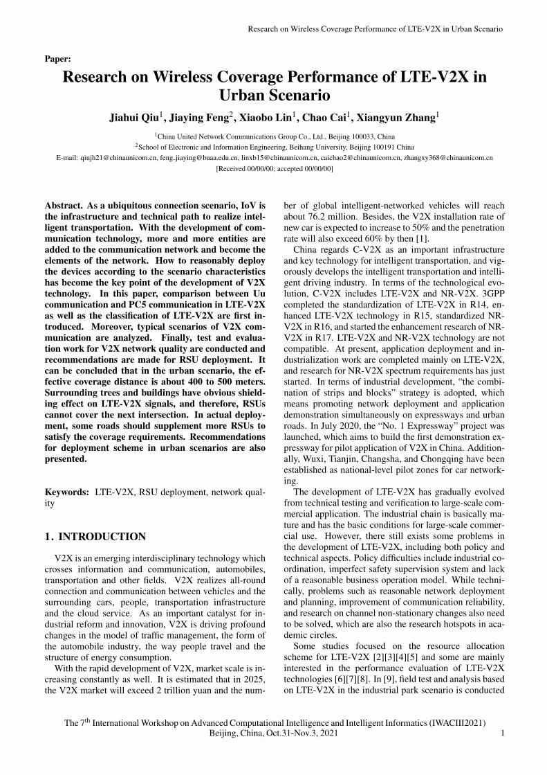
According to the business model, LTE-V2X can bedivided into the following 4 categories[1], as shown inFig.1.
V2N (Vehicle-to-Network) communication, includingdynamic map download, automatic driving related routeplanning, remote control, etc.
V2V (vehicle-to-vehicle) communication, includinganti-collision, congestion avoidance and other securityapplications. V2V security applications are not limitedto network coverage.
V2P (vehicle-to-pedestrian) communication, refers tocommunication between vehicles and pedestrians and ismainly used for pedestrian safety;
V2I (Vehicle-to-Infrastructure) communication, usedto communicate between vehicles and road facilities andtransmit or receive local road traffic information.
3. ANALYSIS OF TYPICAL V2X WIRELESSSCENARIOS
According to the survey, V2X communication mainlyinvolves the following 6 scenarios: urban road, highway,tunnel, overpass, roundabout and parking lot (surface &underground). Wireless channel characteristics, RSU de-ployment locations and service applications are differentin different scenarios. For example, in the urban sce-nario, due to the shielding of buildings, there exists rich
Fig. 1. Classification of LTE-V2X
multipath as well as strong Doppler frequency offset andDoppler spread. In the highway scenario, as there are fewobstructions, field of vision is wide and multipath is fewer.The comparison of channel features, RSU deployment lo-cations and service requirements in different scenarios arepresented in Table 2. Based on the analysis, it can be seenthat RSU deployment schemes vary in different scenar-ios and need to be comprehensively evaluated. Moreover,research on the coverage performance of RSU in differ-ent scenarios is a necessary prerequisite for commerciallarge-scale deployment.
4. TEST AND EVALUATION OF V2X NET-WORK QUALITY
4.1. Test Scheme4.1.1. Test Parameter Definition
(1)PSSCH-RSRPPSSCH-RSRP, abbreviated as RSRP, is the linear aver-
age power (unit: watt) of all Resource Element (RE) ofthe demodulation reference signal carried on the sharedchannel. See 3GPP TS 36.214 for details.
(2)PLRPLR (package loss rate) refers to the ratio of the num-
ber of data packets lost in the test to the data packets sent.LTE-V2X is a broadcast-based communication mode thatguarantees service reliability through blind retransmis-sion, which means every data packet is sent twice to re-duce the packet loss rate. This paper counts PLR in theapplication layer, that is, it does not distinguish betweeninitial transmission packets and retransmission packets.There are two statistical methods for PLR: (a) Since theMsgCount number is continuously accumulated, the re-ceiving end accurately calculates the PLR within a certaintime period by analyzing the MsgCount field in the RSI/ RSM message. (b) RSU is configured to send a certainnumber of V2X messages, and the receiving end countsthe lost packets and divides them.
4.1.2. Test Device Requirements
(1)Transmitting EndThe transmitting end of V2X data shall comply with
the Technical Requirements in Appendix A.
The 7th International Workshop on Advanced Computational Intelligence and Intelligent Informatics (IWACIII2021)2 Beijing, China, Oct.31-Nov.3, 2021
Research on Wireless Coverage Performance of LTE-V2X in Urban Scenario
Table 1. Comparison Between Uu Communication and PC5 Communication
Comparison Item PC5 Interface Communication (V2X-Direct) Uu Interface Communication (V2X-Cellular)Features (1) Low latency, small coverage area, high
moving speed;(2) Suitable for traffic safety and local trafficefficiency service;(3) Use V2X special frequency band (5.9GHz);
(1) Wide coverage, transmitted back to thecloud platform, support higher moving speed;(2) Suitable for infotainment and wide-areatraffic efficiency service;(3) Use cellular network frequency band(3.5GHz) and transmit through cellular net-work Uu interface;
Enhancements (1) Enhanced structure for problems caused byhigh-speed movement;(2) Multiple information transmission periodsfor various business needs;(3) Congestion control mechanism for high-density vehicle scenarios;(4) Location-based spectrum pool resourceplanning and scheduling management;(5) Self-perceived resources and self- organiz-ing communication methods;(6) Multiple synchronization methods for vehi-cle terminal
(1) Local downlink broadcast to satisfy low de-lay requirement;(2) QoS settings for V2X applications;(3) Multiple information transmission periodsfor various business needs
Table 2. Typical scene library classification
Scene Wireless Environment Characteristic RSU Deployment Typical ApplicationUrban Road much shielding;
rich multipath with LOS and NLOS paths;strong Doppler frequency shift and Doppler spread
on electric policepoles /signal lightpoles /street lightpoles
FCW1, ICW2, LTA3,BSW/LCW4,DNPW5, CLW6,HLW7, RLVW8,VRUCW9
Highway wide field of vision with no shielding and reflection;few multipath with strong LOS path;strong Doppler frequency shift caused by high speed
on the gantry FCW, ICW, LTA,BSW/LCW, DNPW,SLW10
Tunnel narrow and small space;rich multipath caused by reflections;strong Doppler frequency shift and Doppler spread
on the sidewall andthe top of the tunnel
DNPW, EBW11 ,AVW12, CLW, HLW,SLW
Overpass wide field of vision with no shielding;few multipath with strong LOS path;long propagation distance
around the overpass EBW, CLW, SLW
Roundabout wide field of vision with no tall buildings;few multipath with strong LOS path;weak Doppler frequency shift
on electric policepoles and signallight poles
ICW, AVW
Surface Park-ing Lot
wide field of vision with no shielding around;strong LOS path;weak Doppler frequency shift and Doppler spread
on street light poles ICW, BSW/LCW
UndergroundParking Lot
narrow space with wall shielding;rich multipath with LOS and NLOS paths;weak Doppler frequency shift
on the sidewall andthe top of the park-ing lot
ICW, BSW/LCW
Descriptions for the marked typical application abbreviations are present in Appendix C.
The V2X data transmitter should be configured withdifferent RSU IDs. RSU ID, which is used to uniquelyidentify the RSU in the message body, refers to the ID inthe RSI/RSM message body defined in the third require-ment in Appendix A.
The V2X data transmitter also supports custom sending
parameters, including the content of the package (fillerfields, standard message body and transmission times-tamp), package size (150 bytes, 400 bytes, 600 bytes,1000 bytes or 1300 bytes), transmission frequency (10Hz)and the number of packages to be sent (>1000).
The 7th International Workshop on Advanced Computational Intelligence and Intelligent Informatics (IWACIII2021)Beijing, China, Oct.31-Nov.3, 2021 3
Jiahui Qiu, Jiaying Feng, Xiaobo Lin, Chao Cai, Xiangyun Zhang
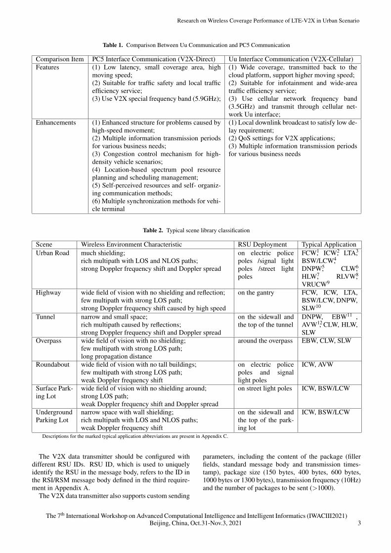
(a) Test Route in Shougang Park (b) Real Image of Qunminghu South-bound Intersection
Fig. 2. Real Image of the test area
(2)Receiving EndThe receiving end of V2X data shall comply with the
Technical Requirements in Appendix A.Compared with the commercial on-board terminals, the
V2X data receiver should additionally provide the outputof network performance parameters and statistical infor-mation, as shown in Table 3.
4.1.3. Test Method
(1)Coverage TestCoverage test is a test for the whole target area. RSUs
in this area are configured to work regularly and transmitRSM, RSI, SPAT and MAP messages periodically. Thereceiving end traverses the road surface at a speed of lessthan 10km/h. The road detector receives the messagestransmitted by the RSUs, including RSRP, RSSI and SNR,and imports the results into the platform for analysis andintegration.
(2)Dotting TestDotting test is the test for a single RSU. Generally, the
test starts directly under the RSU, and then the distancegradually extends. At each test point, “MsgCount” in theRSI/RSM message is used to count PLR for the normallyworking RSU device. Dotting test is used to supplementthe coverage test in the under-covered area to observewhether the PLR of the location can meet the businessrequirements.
4.2. Urban Scenario Test4.2.1. Scenario Description
The test site is located in Beijing Shougang WinterOlympic Park, No.68, Shijingshan Road, ShijingshanDistrict, Beijing. Several RSU devices are distributed in-side Shougang Park. This test is performed with an RSUdevice deployed at the intersection of Qunming Lake,which is deployed on the traffic light pole at the southside of the intersection, about 5 meters from the ground,with a transmission power of 23dBm and antenna gain ofabout 6-7dBi.
4.2.2. Test Analysis
(1)Dotting Test
Dotting test is carried out along the south and the westdirections separately, the route of which is indicated bythe red arrow in Fig.2(a) and the step length is about 30-50 meters. At each test point, the size of test package is400 bytes and a total of 1000 packages are sent. The testterminal receives and counts the number of packages re-ceived. The main purpose of this test is to find out thetrends of V2X network performance with the change ofdistance and with the influence of the surrounding envi-ronment in the urban scenario.
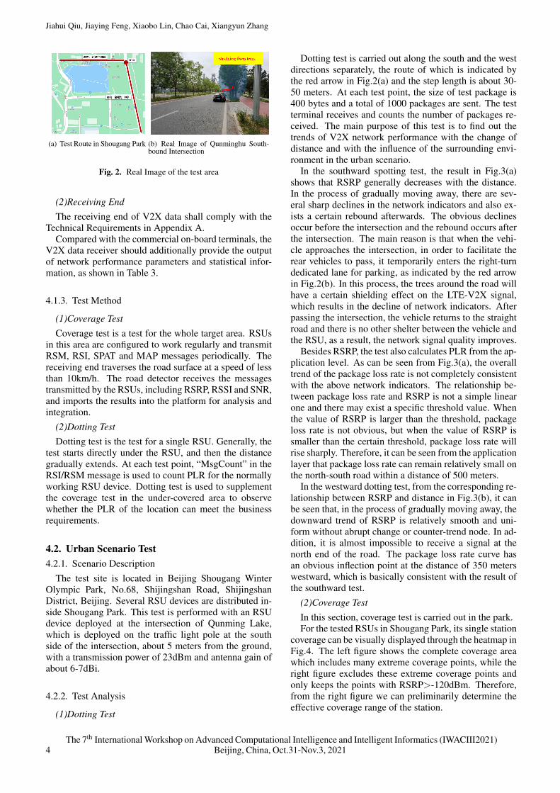
In the southward spotting test, the result in Fig.3(a)shows that RSRP generally decreases with the distance.In the process of gradually moving away, there are sev-eral sharp declines in the network indicators and also ex-ists a certain rebound afterwards. The obvious declinesoccur before the intersection and the rebound occurs afterthe intersection. The main reason is that when the vehi-cle approaches the intersection, in order to facilitate therear vehicles to pass, it temporarily enters the right-turndedicated lane for parking, as indicated by the red arrowin Fig.2(b). In this process, the trees around the road willhave a certain shielding effect on the LTE-V2X signal,which results in the decline of network indicators. Afterpassing the intersection, the vehicle returns to the straightroad and there is no other shelter between the vehicle andthe RSU, as a result, the network signal quality improves.
Besides RSRP, the test also calculates PLR from the ap-plication level. As can be seen from Fig.3(a), the overalltrend of the package loss rate is not completely consistentwith the above network indicators. The relationship be-tween package loss rate and RSRP is not a simple linearone and there may exist a specific threshold value. Whenthe value of RSRP is larger than the threshold, packageloss rate is not obvious, but when the value of RSRP issmaller than the certain threshold, package loss rate willrise sharply. Therefore, it can be seen from the applicationlayer that package loss rate can remain relatively small onthe north-south road within a distance of 500 meters.
In the westward dotting test, from the corresponding re-lationship between RSRP and distance in Fig.3(b), it canbe seen that, in the process of gradually moving away, thedownward trend of RSRP is relatively smooth and uni-form without abrupt change or counter-trend node. In ad-dition, it is almost impossible to receive a signal at thenorth end of the road. The package loss rate curve hasan obvious inflection point at the distance of 350 meterswestward, which is basically consistent with the result ofthe southward test.
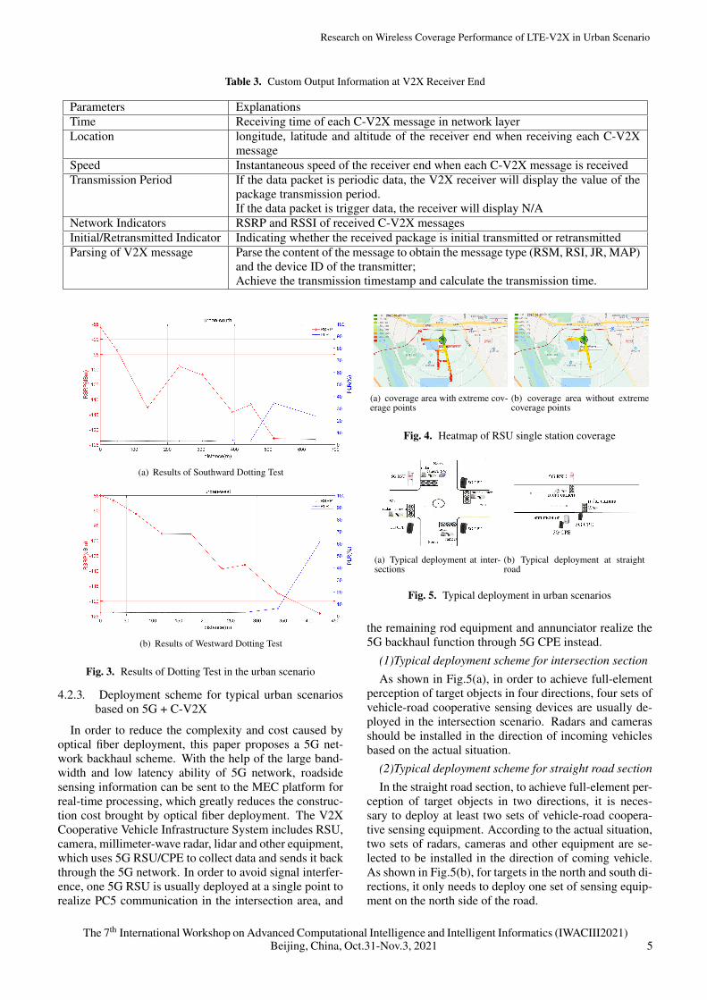
(2)Coverage TestIn this section, coverage test is carried out in the park.For the tested RSUs in Shougang Park, its single station
coverage can be visually displayed through the heatmap inFig.4. The left figure shows the complete coverage areawhich includes many extreme coverage points, while theright figure excludes these extreme coverage points andonly keeps the points with RSRP>-120dBm. Therefore,from the right figure we can preliminarily determine theeffective coverage range of the station.
The 7th International Workshop on Advanced Computational Intelligence and Intelligent Informatics (IWACIII2021)4 Beijing, China, Oct.31-Nov.3, 2021
Research on Wireless Coverage Performance of LTE-V2X in Urban Scenario
Table 3. Custom Output Information at V2X Receiver End
Parameters ExplanationsTime Receiving time of each C-V2X message in network layerLocation longitude, latitude and altitude of the receiver end when receiving each C-V2X
messageSpeed Instantaneous speed of the receiver end when each C-V2X message is receivedTransmission Period If the data packet is periodic data, the V2X receiver will display the value of the
package transmission period.If the data packet is trigger data, the receiver will display N/A
Network Indicators RSRP and RSSI of received C-V2X messagesInitial/Retransmitted Indicator Indicating whether the received package is initial transmitted or retransmittedParsing of V2X message Parse the content of the message to obtain the message type (RSM, RSI, JR, MAP)
and the device ID of the transmitter;Achieve the transmission timestamp and calculate the transmission time.
(a) Results of Southward Dotting Test
(b) Results of Westward Dotting Test
Fig. 3. Results of Dotting Test in the urban scenario
4.2.3. Deployment scheme for typical urban scenariosbased on 5G + C-V2X
In order to reduce the complexity and cost caused byoptical fiber deployment, this paper proposes a 5G net-work backhaul scheme. With the help of the large band-width and low latency ability of 5G network, roadsidesensing information can be sent to the MEC platform forreal-time processing, which greatly reduces the construc-tion cost brought by optical fiber deployment. The V2XCooperative Vehicle Infrastructure System includes RSU,camera, millimeter-wave radar, lidar and other equipment,which uses 5G RSU/CPE to collect data and sends it backthrough the 5G network. In order to avoid signal interfer-ence, one 5G RSU is usually deployed at a single point torealize PC5 communication in the intersection area, and
(a) coverage area with extreme cov-erage points
(b) coverage area without extremecoverage points
Fig. 4. Heatmap of RSU single station coverage
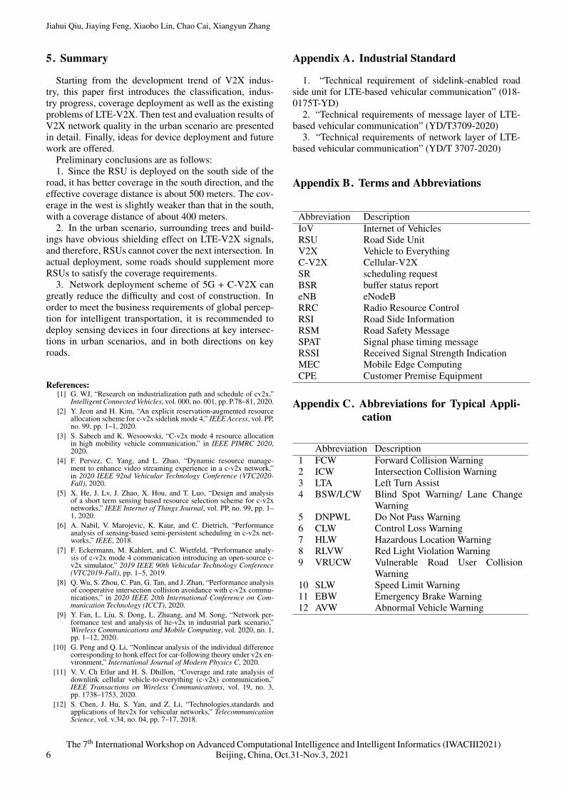
(a) Typical deployment at inter-sections
(b) Typical deployment at straightroad
Fig. 5. Typical deployment in urban scenarios
the remaining rod equipment and annunciator realize the5G backhaul function through 5G CPE instead.
(1)Typical deployment scheme for intersection sectionAs shown in Fig.5(a), in order to achieve full-element
perception of target objects in four directions, four sets ofvehicle-road cooperative sensing devices are usually de-ployed in the intersection scenario. Radars and camerasshould be installed in the direction of incoming vehiclesbased on the actual situation.
(2)Typical deployment scheme for straight road sectionIn the straight road section, to achieve full-element per-
ception of target objects in two directions, it is neces-sary to deploy at least two sets of vehicle-road coopera-tive sensing equipment. According to the actual situation,two sets of radars, cameras and other equipment are se-lected to be installed in the direction of coming vehicle.As shown in Fig.5(b), for targets in the north and south di-rections, it only needs to deploy one set of sensing equip-ment on the north side of the road.
The 7th International Workshop on Advanced Computational Intelligence and Intelligent Informatics (IWACIII2021)Beijing, China, Oct.31-Nov.3, 2021 5
Jiahui Qiu, Jiaying Feng, Xiaobo Lin, Chao Cai, Xiangyun Zhang
5. Summary
Starting from the development trend of V2X indus-try, this paper first introduces the classification, indus-try progress, coverage deployment as well as the existingproblems of LTE-V2X. Then test and evaluation results ofV2X network quality in the urban scenario are presentedin detail. Finally, ideas for device deployment and futurework are offered.
Preliminary conclusions are as follows:1. Since the RSU is deployed on the south side of the
road, it has better coverage in the south direction, and theeffective coverage distance is about 500 meters. The cov-erage in the west is slightly weaker than that in the south,with a coverage distance of about 400 meters.
2. In the urban scenario, surrounding trees and build-ings have obvious shielding effect on LTE-V2X signals,and therefore, RSUs cannot cover the next intersection. Inactual deployment, some roads should supplement moreRSUs to satisfy the coverage requirements.
3. Network deployment scheme of 5G + C-V2X cangreatly reduce the difficulty and cost of construction. Inorder to meet the business requirements of global percep-tion for intelligent transportation, it is recommended todeploy sensing devices in four directions at key intersec-tions in urban scenarios, and in both directions on keyroads.
References:[1] G. WJ, “Research on industrialization path and schedule of cv2x,”
Intelligent Connected Vehicles, vol. 000, no. 001, pp. P.78–81, 2020.[2] Y. Jeon and H. Kim, “An explicit reservation-augmented resource
allocation scheme for c-v2x sidelink mode 4,” IEEE Access, vol. PP,no. 99, pp. 1–1, 2020.
[3] S. Sabeeh and K. Wesoowski, “C-v2x mode 4 resource allocationin high mobility vehicle communication,” in IEEE PIMRC 2020,2020.
[4] F. Pervez, C. Yang, and L. Zhao, “Dynamic resource manage-ment to enhance video streaming experience in a c-v2x network,”in 2020 IEEE 92nd Vehicular Technology Conference (VTC2020-Fall), 2020.
[5] X. He, J. Lv, J. Zhao, X. Hou, and T. Luo, “Design and analysisof a short term sensing based resource selection scheme for c-v2xnetworks,” IEEE Internet of Things Journal, vol. PP, no. 99, pp. 1–1, 2020.
[6] A. Nabil, V. Marojevic, K. Kaur, and C. Dietrich, “Performanceanalysis of sensing-based semi-persistent scheduling in c-v2x net-works,” IEEE, 2018.
[7] F. Eckermann, M. Kahlert, and C. Wietfeld, “Performance analy-sis of c-v2x mode 4 communication introducing an open-source c-v2x simulator,” 2019 IEEE 90th Vehicular Technology Conference(VTC2019-Fall), pp. 1–5, 2019.
[8] Q. Wu, S. Zhou, C. Pan, G. Tan, and J. Zhan, “Performance analysisof cooperative intersection collision avoidance with c-v2x commu-nications,” in 2020 IEEE 20th International Conference on Com-munication Technology (ICCT), 2020.
[9] Y. Fan, L. Liu, S. Dong, L. Zhuang, and M. Song, “Network per-formance test and analysis of lte-v2x in industrial park scenario,”Wireless Communications and Mobile Computing, vol. 2020, no. 1,pp. 1–12, 2020.
[10] G. Peng and Q. Li, “Nonlinear analysis of the individual differencecorresponding to honk effect for car-following theory under v2x en-vironment,” International Journal of Modern Physics C, 2020.
[11] V. V. Ch Etlur and H. S. Dhillon, “Coverage and rate analysis ofdownlink cellular vehicle-to-everything (c-v2x) communication,”IEEE Transactions on Wireless Communications, vol. 19, no. 3,pp. 1738–1753, 2020.
[12] S. Chen, J. Hu, S. Yan, and Z. Li, “Technologies,standards andapplications of ltev2x for vehicular networks,” TelecommunicationScience, vol. v.34, no. 04, pp. 7–17, 2018.
Appendix A. Industrial Standard
1. “Technical requirement of sidelink-enabled roadside unit for LTE-based vehicular communication” (018-0175T-YD)
2. “Technical requirements of message layer of LTE-based vehicular communication” (YD/T3709-2020)
3. “Technical requirements of network layer of LTE-based vehicular communication” (YD/T 3707-2020)
Appendix B. Terms and Abbreviations
Abbreviation DescriptionIoV Internet of VehiclesRSU Road Side UnitV2X Vehicle to EverythingC-V2X Cellular-V2XSR scheduling requestBSR buffer status reporteNB eNodeBRRC Radio Resource ControlRSI Road Side InformationRSM Road Safety MessageSPAT Signal phase timing messageRSSI Received Signal Strength IndicationMEC Mobile Edge ComputingCPE Customer Premise Equipment
Appendix C. Abbreviations for Typical Appli-cation
Abbreviation Description1 FCW Forward Collision Warning2 ICW Intersection Collision Warning3 LTA Left Turn Assist4 BSW/LCW Blind Spot Warning/ Lane Change
Warning5 DNPWL Do Not Pass Warning6 CLW Control Loss Warning7 HLW Hazardous Location Warning8 RLVW Red Light Violation Warning9 VRUCW Vulnerable Road User Collision
Warning10 SLW Speed Limit Warning11 EBW Emergency Brake Warning12 AVW Abnormal Vehicle Warning
The 7th International Workshop on Advanced Computational Intelligence and Intelligent Informatics (IWACIII2021)6 Beijing, China, Oct.31-Nov.3, 2021