Embed Size (px)
Citation preview
Journal of Communications and Information Networks, Vol.2, No.2, Jun. 2017
DOI: 10.1007/s41650-017-0022-x
c© Posts & Telecom Press and Springer Singapore 2017
Special Issue on Internet of Vehicle
Research paper
Link level performance comparison between
LTE V2X and DSRC
Jinling Hu1, Shanzhi Chen1, Li Zhao1, Yuanyuan Li1, Jiayi Fang1, Baozhu Li2*, Yan Shi2
1. State Key Laboratory of Wireless Mobile Communications, China Academy of Telecommunications
Technology, Beijing 100191, China
2. State Key Laboratory of Networking and Switching Technology, Beijing University of Posts
and Telecommunications, Beijing 100876, China
* Corresponding author, Email: tiger [email protected]
Abstract: Applications of VANETs (Vehicular Ad hoc Networks) have their own requirements and
challenges in wireless communication technology. Although regarded as the first standard for VANETs, IEEE
802.11p is still in the field-trial stage. Recently, LTE V2X (Long-Term Evolution Vehicular to X) appeared as
a systematic V2X solution based on TD-LTE (Time Division Long-Term Evolution) 4G. It is regarded as the
most powerful competitor to 802.11p. We conduct link level simulations of LTE V2X and DSRC (Dedicated
Short-Range Communication) for several different types of scenarios. Simulation results show that LTE V2X
can achieve the same BLER (Block Error Ratio) with a lower SNR (Signal Noise Ratio) than DSRC. A more
reliable link can be guaranteed by LTE V2X, which can achieve the same BLER with lower receiving power
than DSRC. The coverage area of LTE V2X is larger than that of DSRC.
Keywords: LTE V2X, DSRC, link level simulation, frequency offset estimation, VANET
- - - - - - - - - - - - - - - - - - - - - - - - - - - - - - - - - - - - - - - - - - - - - - - - - - - - - - - - - - - - - - - - - - - - - - - - - - - - - - - - - - - - - - - - - - - - - - - - - - - - -
Citation: J. L. Hu, S. Z. Chen, L. Zhao, et al. Link level performance comparison between LTE V2X and
DSRC [J]. Journal of communications and information networks, 2017, 2(2): 101-112.
- - - - - - - - - - - - - - - - - - - - - - - - - - - - - - - - - - - - - - - - - - - - - - - - - - - - - - - - - - - - - - - - - - - - - - - - - - - - - - - - - - - - - - - - - - - - - - - - - - - - -
1 Introduction
Vehicular Ad hoc Networks have attracted much at-
tention from academia and industry recently owing
to the broad range of new applications of wireless
communication technologies. Existing V2V (Vehicle-
to-Vehicle) direct communication together with V2I
(Vehicle-to-Infrastructure) communication use wire-
less data communication between vehicles and be-
tween vehicles and RSUs (Road-Side Units). This
can significantly decrease the number of accidents
on the roads. All kinds of applications are emerging.
Lane departure warning and assistance, cooperating
safety systems and emergency vehicle routing are ex-
amples of applications[1].
These traffic safety related systems indicate an in-
creased number of requirements and challenges for
wireless communication. The unpredictable behav-
ior of wireless channels needs to be overcomed. In
addition, developers must cope with fast vehicular
movement, rapid topology changes in vehicular net-
works, and strict timing and reliability requirements.
Timing requirements can be deduced from the fact
that it is only relevant to communication about an
Manuscript received Jan. 25, 2017; accepted Apr. 18, 2017
This work is supported in part by the National Science and Technology Major Projects of China (No. 2017ZX03001014), the
National Science Fund for Distinguished Young Scholars (No. 61425012) and the National Science Foundation Project (No.
61300183).
102 Journal of Communications and Information Networks
upcoming dangerous situation before the situation
is a fact, and perhaps can be avoided (e.g., report a
probable collision before the vehicles collide)[2]. One
thing we need to consider is how shared channels
should be fairly divided among vehicle nodes. This
is accomplished through MAC (Medium Access Con-
trol) mechanism. A lot of attention has been de-
voted to improving MAC performance by introduc-
ing different QoS (Quality of Service) classes[3]. The
MAC layer is unlikely to need many different ser-
vice classes. However, to ensure that time-critical
communication tasks meet their deadlines, the MAC
mechanism must first provide a strict and finite ac-
cess time to the channel. Once channel access is
successful, different coding strategies, retransmission
schemes, and diversity techniques can be used to
finish the required correctness and robustness. In-
formation delivered after the deadline is not only
useless but also wastes time and precious resources,
and poses severe consequences for traffic safety. This
problem has also been pointed out in Ref. [4].
Many wireless technologies can provide the wire-
less access required by vehicular Ad hoc communica-
tions. These technologies include cellular networks
(3G and 4G), traditional Wi-Fi, IEEE 802.11p,
and even infrared communications[5,6]. Owing to
their small communication range, traditional Wi-
Fi and infrared communications are not appropriate
for supporting high mobility and frequent topology
changes[5]. Although people can use cellular net-
works, they suffer from low rates, high costs, and
long latencies. In these technologies, although IEEE
802.11p as the first standard specifically for vehicular
networks has arisen, it has obvious weaknesses such
as hidden node problems, unbounded delays, low
reliability and intermittent V2I connectivity[7-10].
From an industrial perspective, the wide deploy-
ment of IEEE 802.11p network infrastructure re-
quires huge investments. A lot of effort has been
made by using LTE as a promising wireless technol-
ogy to support vehicular communications[11,12].
Owing to its high penetration rate, high data
rate, large coverage, and comprehensive QoS sup-
porting, LTE has inherent advantages in support-
ing V2I communications. However, LTE faces severe
challenges when being applied in V2V communica-
tions for the following reasons: the heavy load caused
by safety-related and periodic messages strongly in-
fluences LTE capacity and potentially disadvantages
traditional applications, and its centralized mode has
no support for V2V communications[7]. Extend-
ing LTE with direct communications between ve-
hicles will be a promising solution, because cellu-
lar and Ad hoc communications are suggested to be
complementary[13,14].
Vehicular networks mainly provide safer, more
comfortable driving and traffic efficiency; however, if
we do not ensure the reliability (error probability) of
a system supported by a PHY (Physical) layer, the
benefits of vehicular networks cannot be exploited
and utilized. We need to investigate the character-
istics of the PHY layer of LTE V2X and DSRC to
evaluate their BLER performance. In this paper, we
conduct a link level evaluation between LTE-V2X
and DSRC by using an extensive simulation. By
the evaluation based on simulation, we derive that
the performance of the PHY layer of LTE V2X is
obviously superior to that of DSRC with regard to
simulation parameters such as different traveling ve-
locities and different packet sizes.
The rest of the paper is organized as follows: A
comparison between LTE V2X and DSRC on the
physical level is discussed in section 2, which includes
the coding scheme and frequency offset estimation
algorithm. In section 3 we conduct a simulation
and performance evaluation between LTE V2X and
DSRC in all kinds of scenarios including different rel-
ative velocities and a fast fading model. Concluding
remarks and future work are given in section 4.
2 Comparison between LTE V2X and
DSRC
In the section, we mainly focus on a comparison be-
tween LTE V2X and DSRC on the physical level. In
the next section, we conduct link level simulations
on LTE V2X and DSRC to evaluate their link per-
formances in different scenarios.
Link level performance comparison between LTE V2X and DSRC 103
2.1 DSRC
The US FCC (Federal Communication Commission)
allocated 75 MHz of the spectrum for V2V and
V2I communications. The main purpose is to en-
able safety-related applications in vehicular networks
to improve traffic conditions and prevent accidents
(traffic safety). There are two types of channels in
DSRC, each of them with a 10-MHz bandwidth: the
SCH (Service Channel) and the CCH (Control Chan-
nel). SCHs are available both for safety and non-
safety use, and CCHs are restricted to safety com-
munications only. Applications for vehicular com-
munications can be placed in three main categories:
traffic safety, traffic efficiency and value-added ser-
vices (e.g., infotainment/business)[15-17].
The DSRC band is a free yet licensed spectrum.
Because the FCC does not charge a fee for spectrum
usage, it is free. However, we should not confuse this
with the unlicensed bands at 900 MHz, 2.4 GHz, and
5 GHz, which are also free for use. These unlicensed
bands place no restrictions on the technologies other
than some emission and co-existence rules. On the
other hand, usage of the DSRC band is more re-
stricted. FCC rulings regulate usage within certain
channels and limit all radios to be compliant with a
standard. In other words, although DSRC is limited
in transmission power with regard to the unlicensed
band, one cannot develop a different radio technol-
ogy (e.g., one that uses all 75 MHz of the spectrum)
in the DSRC band. These DSRC usage rules are
referred as “license by rule.”
2.1.1 Physical layer architecture
The physical layer standard is made up of two sub-
layers: the PMD (Physical Medium Dependent) sub-
layer and PLCP (Physical Layer Convergence Proto-
col) sublayer. The PMD sublayer defines the param-
eters to establish the signal, such as channel coding,
modulation, and demodulation. On the other hand,
the PLCP sublayer deals with interference between
different PHY layers and makes sure that the MAC
layer receives the data in a common format, inde-
pendent of the particular PMD sublayer. Through
the correspondent SAPs (Service Access Points), the
PLCP communicates with the PMD sublayer and
MAC layer.
2.1.2 Coding scheme: convolutional code
In DSRC, convolutional code is used. This is also
called NSC (Nonsystematic Convolutional) codes.
2.1.3 DSRC frequency offset estimation al-
gorithm
For the DSRC receiver, there are two steps to es-
timate and correct frequency errors. The detailed
steps can be seen in Algorithm 1.
Algorithm 1 DSRC frequency offset estimation
1: The short training sequences (for coarse frequency off-
set estimation) and the long training sequence (for fine
frequency offset estimation) are utilized in the PLCP
preamble to correct the frequency error, and the inte-
ger and non-integer parts of the frequency error can
be corrected at the same time;
2: Four pilot subcarriers of every OFDM symbol are used
for carrier phase tracking to alleviate the residual fre-
quency error and phase noise.
The short training sequence is defined as 1.6 us,
and the FFT/IFFT period for the 10-MHz band-
width is 6.4 us in IEEE 802.11p protocols. Because
the phase offset of the neighboring short training se-
quence is limited to π, the maximum frequency error
estimation of the 10-MHz DSRC can be two times
the subcarrier spacing, theoretically. Though the
fixed frequency error X = 40 ppm (236 kHz) for
DSRC is higher than the subcarrier spacing of 156
kHz, the fixed frequency error of 236 kHz is lower
than the theoretical maximum frequency error esti-
mation of 312 kHz of the 10-MHz DSRC. Then, the
frequency compensation can be based on the estima-
tion of the frequency error. The fixed frequency error
of 40 ppm (236 kHz) can be compensated with short
and long training sequences simultaneously for the
integer and non-integer parts of the frequency error.
104 Journal of Communications and Information Networks
2.2 LTE V2X
LTE V2X based on TD-LTE 4G is a systematic V2X
solution. LTE V2X consists of two modes: LTE-
V-Direct and LTE-V-Cell. Compared with IEEE
802.11p, LTE-V-Direct is a new distributed archi-
tecture. It changes the TD-LTE physical layer
and attempts to provide high-reliability improve-
ments, short-range direct communication, and low
latency by maintaining commonality. By leverag-
ing the centralized architecture, LTE-V-Cell opti-
mizes RRM (Radio Resource Management) to bet-
ter support V2I communications. LTE-V-Direct and
LTE-V-Cell work together with each other to provide
promising V2X solutions.
2.2.1 Frame structure
Fig. 1 shows the frame structure of LTE V2X. In
the frame structure, there are 14 TTIs (Transmission
Time Intervals), in which four DMRS (Demodulation
Reference Signals) and one GP (Guard Period) are
included, and the rest are data symbols.
GPDMRS
DMRS
DMRS
DMRS
Figure 1 Frame structure of LTE V2X
For V2V, the data frame structure of D2D defined
in 3GPP TS 36.211 and 3GPP TS 36.212 is reused:
there are 14 symbols in one TTI that lasts 1 ms, and
the last symbol is used as a guard period.
In PSSCH/PSCCH/PSDCH of 3GPP Rel 12/13
D2D, there are two DMRSs per PRB, and the inter-
val time of the DMRS is 0.5 ms. When the speed of
the mobile terminal is high, such as 140 km/h, and
the signal’s center frequency is 6.0 GHz, the coher-
ence time (about 0.277 ms) of the signal will be lower
than the current time interval of DMRS (about 0.5
ms). Hence, the demodulation performance of the
data will fall sharply owing to poor channel estima-
tion and a consequential lack of channel information.
There is a consensus that DMRS density in the time
domain should be increased to four symbols.
2.2.2 Coding scheme: Turbo code
In LTE V2X, we use turbo code which is one of
the most powerful types of FEC (Forward-Error-
Correcting) channel codes. The best-known convo-
lutional codes are mostly nonsystematic. However,
systematic convolutional codes are used in turbo en-
coders (i.e., the encoder’s input bits appear at the
output). Unlike nonsystematic code, a systematic
code word can be divided into data and parity com-
ponents. Turbo codes are produced by using the
parallel concatenation of two RSC (Recursive Sys-
tematic Convolutional) encoders. This is one of the
most interesting characteristics: that it is not just
a single code, but is also in fact a combination of
two codes that work together to achieve a synergy.
It would be impossible by merely using one code by
itself. In particular, a turbo code is formed from
the parallel concatenation of two constituent codes
separated by an interleaver. Each constituent code
may be any type of FEC code used for conventional
data communications. Although the two constituent
encoders may be different, in fact they are normally
identical. The interleaver is a critical part of the
turbo code. It is a simple device that changes the
order of the data bits.
2.2.3 LTE V2X frequency offset estimation
algorithm
For the DSRC receiver, there are six steps to esti-
mate and correct the frequency error. The detailed
steps can be seen in Algorithm 2.
3 Simulation and performance evalu-
ation
We conducted extensive link level simulations of LTE
V2X and DSRC using our simulator coded in MAT-
LAB by CATT, and analyzed a comparison and per-
formance evaluation of the two links based on the
simulation results (i.e., SINR-BLER and the receiv-
ing power with BLER). Our simulation assumptions
are based on the parameters listed in Tab. 1, and all
assumptions were agreed to during the NGMN V2X
Link level performance comparison between LTE V2X and DSRC 105
task force F2F meeting[14,18,19] in September 2016.
For frequency errors in Tab. 1, we set the values
based on the maximum allowable deviations these
two systems can tolerate. Extensive simulations were
conducted for the urban case with relative speeds of
30 km/h and 120 km/h and the freeway case with
relative speeds of 280 km/h and 500 km/h. Only
the performance metrics of BLER are compared in
this paper. We will compare some other performance
metrics in the future. In addition, in all figures, fix
CFO means a fixed central frequency offset, and rand
CFO means a random central frequency offset.
Algorithm 2 LTE V2X frequency offset estimation
1: Timing detection by searching the peak of channel es-
timation transformed to the time domain, → d;
2: Local DMRS sequence is transformed to the time do-
main, → P (n);
3: Sequence shift of sequence in Step 2 according to tim-
ing in Step 1, → P̃ (n) = P (mod(n+ d,N));
4: Received DMRS symbol is transformed to the time
domain, → r(n);
5: Correlation is done for sequence in Step 3 and Step 4;
6: Frequency offset is estimated by comparing the angle
difference of first half and second half of sequence in
Step 5.
f =1
2π∆t tan−1
{N/2−1∑n=0
P̃ (n)r(n)
}
×{N/2−1∑
n=0
P̃ (n+N
2)r(n+
N
2)
}
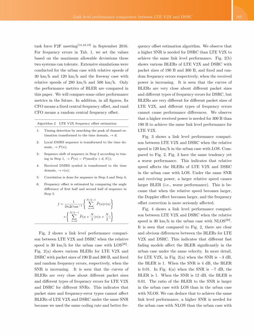
Fig. 2 shows a link level performance compari-
son between LTE V2X and DSRC when the relative
speed is 30 km/h for the urban case with LOS[20].
Fig. 2(a) shows various BLERs for LTE V2X and
DSRC with packet sizes of 190 B and 300 B, and fixed
and random frequency errors, respectively, when the
SNR is increasing. It is seen that the curves of
BLERs are very close about different packet sizes
and different types of frequency errors for LTE V2X
and DSRC for different SNRs. This indicates that
packet sizes and frequency-error types cannot affect
BLERs of LTE V2X and DSRC under the same SNR
because we used the same coding rate and better fre-
quency offset estimation algorithm. We observe that
a higher SNR is needed for DSRC than LTE V2X to
achieve the same link level performance. Fig. 2(b)
shows various BLERs of LTE V2X and DSRC with
packet sizes of 190 B and 300 B, and fixed and ran-
dom frequency errors respectively, when the received
power is increasing. It is seen that the curves of
BLERs are very close about different packet sizes
and different types of frequency errors for DSRC, but
BLERs are very different for different packet sizes of
LTE V2X, and different types of frequency errors
cannot cause performance differences. We observe
that a higher received power is needed for 300 B than
190 B to achieve the same link level performance for
LTE V2X.
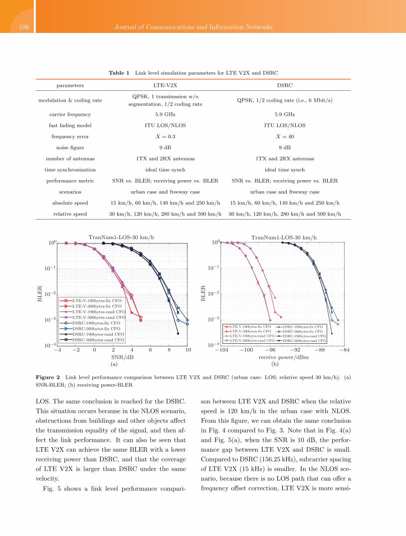
Fig. 3 shows a link level performance compari-
son between LTE V2X and DSRC when the relative
speed is 120 km/h in the urban case with LOS. Com-
pared to Fig. 2, Fig. 3 have the same tendency yet
a worse performance. This indicates that relative
speed affects the BLERs of LTE V2X and DSRC
in the urban case with LOS. Under the same SNR
and receiving power, a larger relative speed causes
larger BLER (i.e., worse performance). This is be-
cause that when the relative speed becomes larger,
the Doppler effect becomes larger, and the frequency
offset correction is more seriously affected.
Fig. 4 shows a link level performance compari-
son between LTE V2X and DSRC when the relative
speed is 30 km/h in the urban case with NLOS[20].
It is seen that compared to Fig. 2, there are clear
and obvious differences between the BLERs for LTE
V2X and DSRC. This indicates that different fast
fading models affect the BLER significantly in the
urban case under the same velocity. In more detail,
for LTE V2X, in Fig. 2(a) when the SNR is −3 dB,
the BLER is 1. When the SNR is 4 dB, the BLER
is 0.01. In Fig. 4(a) when the SNR is −7 dB, the
BLER is 1. When the SNR is 12 dB, the BLER is
0.01. The ratio of the BLER to the SNR is larger
in the urban case with LOS than in the urban case
with NLOS. We can deduce that to achieve the same
link level performance, a higher SNR is needed for
the urban case with NLOS than the urban case with
106 Journal of Communications and Information Networks
Table 1 Link level simulation parameters for LTE V2X and DSRC
parameters LTE-V2X DSRC
modulation & coding rateQPSK, 1 transimssion w/o
segmentation, 1/2 coding rateQPSK, 1/2 coding rate (i.e., 6 Mbit/s)
carrier frequency 5.9 GHz 5.9 GHz
fast fading model ITU LOS/NLOS ITU LOS/NLOS
frequency error X = 0.3 X = 40
noise figure 9 dB 9 dB
number of antennas 1TX and 2RX antennas 1TX and 2RX antennas
time synchronization ideal time synch ideal time synch
performance metric SNR vs. BLER; receiving power vs. BLER SNR vs. BLER; receiving power vs. BLER
scenarios urban case and freeway case urban case and freeway case
absolute speed 15 km/h, 60 km/h, 140 km/h and 250 km/h 15 km/h, 60 km/h, 140 km/h and 250 km/h
relative speed 30 km/h, 120 km/h, 280 km/h and 500 km/h 30 km/h, 120 km/h, 280 km/h and 500 km/h
−4 −2 0 2 4 6 8 1010−4
10−3
10−2
10−1
100
SNR/dB
BLE
R
TranNum1-LOS-30 km/h
LTE-V-190bytes-fix CFO
LTE-V-300bytes-fix CFO
LTE-V-190bytes-rand CFO
LTE-V-300bytes-rand CFO
DSRC-190bytes-fix CFO
DSRC-300bytes-fix CFO
DSRC-190bytes-rand CFO
DSRC-300bytes-rand CFO
(a)
−104 −100 −96 −92 −88 −84
receive power/dBm
10−4
10−3
10−2
10−1
100
BLE
R
TranNum1-LOS-30 km/h
LTE-V-190bytes-fix CFO
LTE-V-300bytes-fix CFO
LTE-V-190bytes-rand CFO
LTE-V-300bytes-rand CFO
DSRC-190bytes-fix CFO
DSRC-300bytes-fix CFO
DSRC-190bytes-rand CFO
DSRC-300bytes-rand CFO
(b)
Figure 2 Link level performance comparison between LTE V2X and DSRC (urban case: LOS; relative speed 30 km/h). (a)
SNR-BLER; (b) receiving power-BLER
LOS. The same conclusion is reached for the DSRC.
This situation occurs because in the NLOS scenario,
obstructions from buildings and other objects affect
the transmission equality of the signal, and then af-
fect the link performance. It can also be seen that
LTE V2X can achieve the same BLER with a lower
receiving power than DSRC, and that the coverage
of LTE V2X is larger than DSRC under the same
velocity.
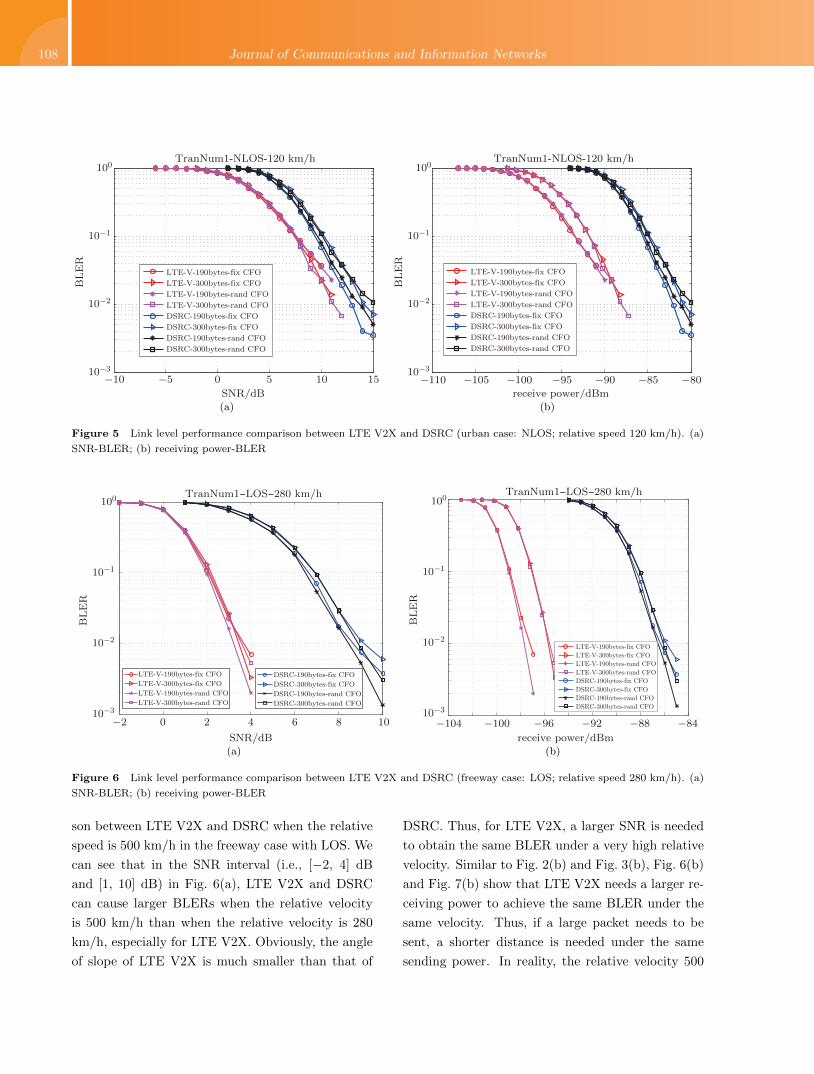
Fig. 5 shows a link level performance compari-
son between LTE V2X and DSRC when the relative
speed is 120 km/h in the urban case with NLOS.
From this figure, we can obtain the same conclusion
in Fig. 4 compared to Fig. 3. Note that in Fig. 4(a)
and Fig. 5(a), when the SNR is 10 dB, the perfor-
mance gap between LTE V2X and DSRC is small.
Compared to DSRC (156.25 kHz), subcarrier spacing
of LTE V2X (15 kHz) is smaller. In the NLOS sce-
nario, because there is no LOS path that can offer a
frequency offset correction, LTE V2X is more sensi-
Link level performance comparison between LTE V2X and DSRC 107
−4 −2 0 2 4 6 8 1010−4
10−3
10−2
10−1
100
SNR/dB
BLE
R
TranNum1-LOS-120 km/h
LTE-V-190bytes-fix CFO
LTE-V-300bytes-fix CFO
LTE-V-190bytes-rand CFO
LTE-V-300bytes-rand CFO
DSRC-190bytes-fix CFO
DSRC-300bytes-fix CFO
DSRC-190bytes-rand CFO
DSRC-300bytes-rand CFO
(a)
−104 −100 −96 −92 −88 −84
receive power/dBm
10−4
10−3
10−2
10−1
100
BLE
R
TranNum1-LOS-120 km/h
LTE-V-190bytes-fix CFO
LTE-V-300bytes-fix CFO
LTE-V-190bytes-rand CFO
LTE-V-300bytes-rand CFO
DSRC-190bytes-fix CFO
DSRC-300bytes-fix CFO
DSRC-190bytes-rand CFO
DSRC-300bytes-rand CFO
(b)
Figure 3 Link level performance comparison between LTE V2X and DSRC (urban case: LOS; relative speed 120 km/h). (a)
SNR-BLER; (b) receiving power-BLER
−10 −5 0 5 10 1510−3
10−2
10−1
100
SNR/dB
BLE
R
TranNum1-NLOS-30 km/h
LTE-V-190bytes-fix CFO
LTE-V-300bytes-fix CFO
LTE-V-190bytes-rand CFO
LTE-V-300bytes-rand CFO
DSRC-190bytes-fix CFO
DSRC-300bytes-fix CFO
DSRC-190bytes-rand CFO
DSRC-300bytes-rand CFO
(a)
−110 −105 −100 −95 −90 −85 −80receive power/dBm
TranNum1-NLOS-30 km/h
LTE-V-190bytes-fix CFO
LTE-V-300bytes-fix CFO
LTE-V-190bytes-rand CFO
LTE-V-300bytes-rand CFO
DSRC-190bytes-fix CFO
DSRC-300bytes-fix CFO
DSRC-190bytes-rand CFO
DSRC-300bytes-rand CFO
10−3
10−2
10−1
100
BLE
R
(b)
Figure 4 Link level performance comparison between LTE V2X and DSRC (urban case: NLOS; relative speed 30 km/h). (a)
SNR-BLER; (b) receiving power-BLER
tive to frequency offset effects than DSRC. Moreover,
for LTE V2X, the channel estimation is less accurate.
These two reasons result in the phenomenon that the
curves of LTE V2X and DSRC are very close.
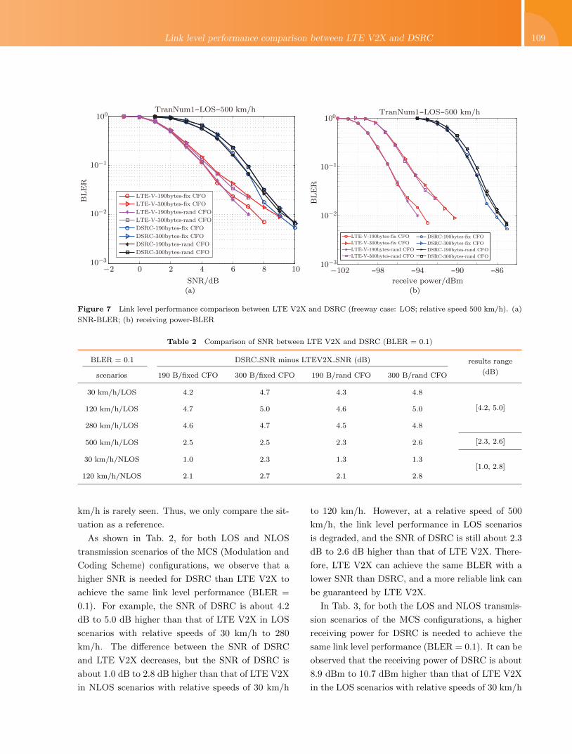
Fig. 6 shows a link level performance compari-
son between LTE V2X and DSRC when the relative
speed is 280 km/h in the freeway case with LOS. As
depicted in Fig. 2 and Fig. 3, we can see that DSRC
needs a larger SNR and receiving power to obtain the
same BLER as LTE V2X in the freeway case with
LOS. However, compared to Fig. 2 and Fig. 3, the
performances of LTE V2X and DSRC in Fig. 6 do
not obviously decline. This is because the frequency
offset estimation for LTE V2X is very accurate and
when the relative speed is 30 km/h, channel fading
is more serious. This indicates that under a larger
relative velocity in the freeway case, LTE V2X and
DSRC can obtain the same performance in the LOS
scenario.
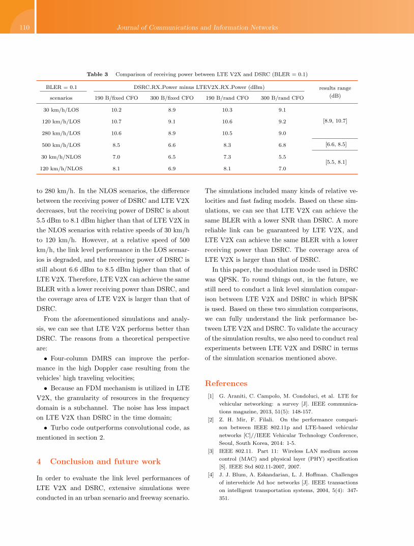
Fig. 7 shows a link level performance compari-
108 Journal of Communications and Information Networks
−10 −5 0 5 10 1510−3
10−2
10−1
100
SNR/dB
BLE
R
TranNum1-NLOS-120 km/h
LTE-V-190bytes-fix CFO
LTE-V-300bytes-fix CFO
LTE-V-190bytes-rand CFO
LTE-V-300bytes-rand CFO
DSRC-190bytes-fix CFO
DSRC-300bytes-fix CFO
DSRC-190bytes-rand CFO
DSRC-300bytes-rand CFO
(a)
−110 −105 −100 −95 −90 −85 −80
receive power/dBm
TranNum1-NLOS-120 km/h
LTE-V-190bytes-fix CFO
LTE-V-300bytes-fix CFO
LTE-V-190bytes-rand CFO
LTE-V-300bytes-rand CFO
DSRC-190bytes-fix CFO
DSRC-300bytes-fix CFO
DSRC-190bytes-rand CFO
DSRC-300bytes-rand CFO
10−3
10−2
10−1
100
BLE
R(b)
Figure 5 Link level performance comparison between LTE V2X and DSRC (urban case: NLOS; relative speed 120 km/h). (a)
SNR-BLER; (b) receiving power-BLER
−2 0 2 4 6 8 10
SNR/dB
TranNum1−LOS−280 km/h
10−3
10−2
10−1
100
BLE
R
LTE-V-190bytes-fix CFO
LTE-V-300bytes-fix CFO
LTE-V-190bytes-rand CFO
LTE-V-300bytes-rand CFO
DSRC-190bytes-fix CFO
DSRC-300bytes-fix CFO
DSRC-190bytes-rand CFO
DSRC-300bytes-rand CFO
(a)
−104 −100 −96 −92 −88 −84
receive power/dBm
TranNum1−LOS−280 km/h
10−3
10−2
10−1
100
BLE
R
LTE-V-190bytes-fix CFO
LTE-V-300bytes-fix CFO
LTE-V-190bytes-rand CFO
LTE-V-300bytes-rand CFO
DSRC-190bytes-fix CFO
DSRC-300bytes-fix CFO
DSRC-190bytes-rand CFO
DSRC-300bytes-rand CFO
(b)
Figure 6 Link level performance comparison between LTE V2X and DSRC (freeway case: LOS; relative speed 280 km/h). (a)
SNR-BLER; (b) receiving power-BLER
son between LTE V2X and DSRC when the relative
speed is 500 km/h in the freeway case with LOS. We
can see that in the SNR interval (i.e., [−2, 4] dB
and [1, 10] dB) in Fig. 6(a), LTE V2X and DSRC
can cause larger BLERs when the relative velocity
is 500 km/h than when the relative velocity is 280
km/h, especially for LTE V2X. Obviously, the angle
of slope of LTE V2X is much smaller than that of
DSRC. Thus, for LTE V2X, a larger SNR is needed
to obtain the same BLER under a very high relative
velocity. Similar to Fig. 2(b) and Fig. 3(b), Fig. 6(b)
and Fig. 7(b) show that LTE V2X needs a larger re-
ceiving power to achieve the same BLER under the
same velocity. Thus, if a large packet needs to be
sent, a shorter distance is needed under the same
sending power. In reality, the relative velocity 500
Link level performance comparison between LTE V2X and DSRC 109
−2 0 2 4 6 8 10
SNR/dB
TranNum1−LOS−500 km/h
LTE-V-190bytes-fix CFO
LTE-V-300bytes-fix CFO
LTE-V-190bytes-rand CFO
LTE-V-300bytes-rand CFO
DSRC-190bytes-fix CFO
DSRC-300bytes-fix CFO
DSRC-190bytes-rand CFO
DSRC-300bytes-rand CFO
10−3
10−2
10−1
100
BLE
R
(a)
−102 −98 −94 −90 −86
receive power/dBm
TranNum1−LOS−500 km/h
10−3
10−2
10−1
100
BLE
R
LTE-V-190bytes-fix CFO
LTE-V-300bytes-fix CFO
LTE-V-190bytes-rand CFO
LTE-V-300bytes-rand CFO
DSRC-190bytes-fix CFO
DSRC-300bytes-fix CFO
DSRC-190bytes-rand CFO
DSRC-300bytes-rand CFO
(b)
Figure 7 Link level performance comparison between LTE V2X and DSRC (freeway case: LOS; relative speed 500 km/h). (a)
SNR-BLER; (b) receiving power-BLER
Table 2 Comparison of SNR between LTE V2X and DSRC (BLER = 0.1)
BLER = 0.1 DSRC SNR minus LTEV2X SNR (dB) results range
(dB)scenarios 190 B/fixed CFO 300 B/fixed CFO 190 B/rand CFO 300 B/rand CFO
30 km/h/LOS 4.2 4.7 4.3 4.8
[4.2, 5.0]120 km/h/LOS 4.7 5.0 4.6 5.0
280 km/h/LOS 4.6 4.7 4.5 4.8
500 km/h/LOS 2.5 2.5 2.3 2.6 [2.3, 2.6]
30 km/h/NLOS 1.0 2.3 1.3 1.3[1.0, 2.8]
120 km/h/NLOS 2.1 2.7 2.1 2.8
km/h is rarely seen. Thus, we only compare the sit-
uation as a reference.
As shown in Tab. 2, for both LOS and NLOS
transmission scenarios of the MCS (Modulation and
Coding Scheme) configurations, we observe that a
higher SNR is needed for DSRC than LTE V2X to
achieve the same link level performance (BLER =
0.1). For example, the SNR of DSRC is about 4.2
dB to 5.0 dB higher than that of LTE V2X in LOS
scenarios with relative speeds of 30 km/h to 280
km/h. The difference between the SNR of DSRC
and LTE V2X decreases, but the SNR of DSRC is
about 1.0 dB to 2.8 dB higher than that of LTE V2X
in NLOS scenarios with relative speeds of 30 km/h
to 120 km/h. However, at a relative speed of 500
km/h, the link level performance in LOS scenarios
is degraded, and the SNR of DSRC is still about 2.3
dB to 2.6 dB higher than that of LTE V2X. There-
fore, LTE V2X can achieve the same BLER with a
lower SNR than DSRC, and a more reliable link can
be guaranteed by LTE V2X.
In Tab. 3, for both the LOS and NLOS transmis-
sion scenarios of the MCS configurations, a higher
receiving power for DSRC is needed to achieve the
same link level performance (BLER = 0.1). It can be
observed that the receiving power of DSRC is about
8.9 dBm to 10.7 dBm higher than that of LTE V2X
in the LOS scenarios with relative speeds of 30 km/h
110 Journal of Communications and Information Networks
Table 3 Comparison of receiving power between LTE V2X and DSRC (BLER = 0.1)
BLER = 0.1 DSRC RX Power minus LTEV2X RX Power (dBm) results range
(dB)scenarios 190 B/fixed CFO 300 B/fixed CFO 190 B/rand CFO 300 B/rand CFO
30 km/h/LOS 10.2 8.9 10.3 9.1
[8.9, 10.7]120 km/h/LOS 10.7 9.1 10.6 9.2
280 km/h/LOS 10.6 8.9 10.5 9.0
500 km/h/LOS 8.5 6.6 8.3 6.8 [6.6, 8.5]
30 km/h/NLOS 7.0 6.5 7.3 5.5[5.5, 8.1]
120 km/h/NLOS 8.1 6.9 8.1 7.0
to 280 km/h. In the NLOS scenarios, the difference
between the receiving power of DSRC and LTE V2X
decreases, but the receiving power of DSRC is about
5.5 dBm to 8.1 dBm higher than that of LTE V2X in
the NLOS scenarios with relative speeds of 30 km/h
to 120 km/h. However, at a relative speed of 500
km/h, the link level performance in the LOS scenar-
ios is degraded, and the receiving power of DSRC is
still about 6.6 dBm to 8.5 dBm higher than that of
LTE V2X. Therefore, LTE V2X can achieve the same
BLER with a lower receiving power than DSRC, and
the coverage area of LTE V2X is larger than that of
DSRC.
From the aforementioned simulations and analy-
sis, we can see that LTE V2X performs better than
DSRC. The reasons from a theoretical perspective
are:
• Four-column DMRS can improve the perfor-
mance in the high Doppler case resulting from the
vehicles’ high traveling velocities;
• Because an FDM mechanism is utilized in LTE
V2X, the granularity of resources in the frequency
domain is a subchannel. The noise has less impact
on LTE V2X than DSRC in the time domain;
• Turbo code outperforms convolutional code, as
mentioned in section 2.
4 Conclusion and future work
In order to evaluate the link level performances of
LTE V2X and DSRC, extensive simulations were
conducted in an urban scenario and freeway scenario.
The simulations included many kinds of relative ve-
locities and fast fading models. Based on these sim-
ulations, we can see that LTE V2X can achieve the
same BLER with a lower SNR than DSRC. A more
reliable link can be guaranteed by LTE V2X, and
LTE V2X can achieve the same BLER with a lower
receiving power than DSRC. The coverage area of
LTE V2X is larger than that of DSRC.
In this paper, the modulation mode used in DSRC
was QPSK. To round things out, in the future, we
still need to conduct a link level simulation compar-
ison between LTE V2X and DSRC in which BPSK
is used. Based on these two simulation comparisons,
we can fully understand the link performance be-
tween LTE V2X and DSRC. To validate the accuracy
of the simulation results, we also need to conduct real
experiments between LTE V2X and DSRC in terms
of the simulation scenarios mentioned above.
References
[1] G. Araniti, C. Campolo, M. Condoluci, et al. LTE for
vehicular networking: a survey [J]. IEEE communica-
tions magazine, 2013, 51(5): 148-157.
[2] Z. H. Mir, F. Filali. On the performance compari-
son between IEEE 802.11p and LTE-based vehicular
networks [C]//IEEE Vehicular Technology Conference,
Seoul, South Korea, 2014: 1-5.
[3] IEEE 802.11. Part 11: Wireless LAN medium access
control (MAC) and physical layer (PHY) specification
[S]. IEEE Std 802.11-2007, 2007.
[4] J. J. Blum, A. Eskandarian, L. J. Hoffman. Challenges
of intervehicle Ad hoc networks [J]. IEEE transactions
on intelligent transportation systems, 2004, 5(4): 347-
351.
Link level performance comparison between LTE V2X and DSRC 111
[5] P. Papadimitratos, A. D. L. Fortelle, K. Evenssen, et
al. Vehicular communication systems: enabling tech-
nologies, applications, and future outlook on intelli-
gent transportation [J]. IEEE communications maga-
zine, 2009, 47(11): 84-95.
[6] S. Al-Sultan , M. M. Al-Doori, A. H. Al-Bayatti, et al.
A comprehensive survey on vehicular Ad hoc network
[J]. Journal of network and computer applications, 2014,
37(1): 380-392.
[7] G. Araniti, C. Campolo, M. Condoluci, et al. LTE for
vehicular networking: a survey [J]. IEEE communica-
tions magazine, 2013, 51(5): 148-157.
[8] M. Amadeo, C. Campolo. Enhancing IEEE 802.11p/
WAVE to provide infotainment applications in VANETs
[J]. Elsevier Ad hoc networks, 2012, 10(2): 253-269.
[9] K. Bilstrup, E. Uhlemann. Does the 802.11p MAC
method provide predictable support for low delay com-
munications? [C]//Proceedings of 1st ETSI Workshop
on ITS, Sophia Antipolis, France, 2009: 1-17.
[10] H. Hartenstein, K. Laberteaux. VANET: vehicular ap-
plications and inter-networking technologies [M]. USA:
John Wiley & Sons, 2010.
[11] L. Gallo, J. Harri. Short paper: a LTE-direct broad-
cast mechanism for periodic vehicular safety communi-
cations [C]//2013 IEEE Vehicular Networking Confer-
ence (VNC 2013), Boston, USA, 2013: 166-169.
[12] S. Kato, M. Hiltunen. Enabling vehicular safety appli-
cations over LTE networks [C]//2013 International Con-
ference on Connected Vehicles and Expo (ICCVE 2013),
Las Vegas, USA, 2013: 747-752.
[13] K. Bilstrup. A survey regarding wireless communication
standards intended for a high-speed vehicle environment
[R]. Halmstad: Halmstad University, 2007.
[14] S. Z. Chen, J. L. Hu, Y. Shi, et al. LTE-V: a TD-
LTE based V2X solution for future vehicular network
[J]. IEEE Internet of Things journal, 2016, 3(6): 997-
1005.
[15] H. Lans. Position indicating system [P]. US Patent
5506587, 1996.
[16] R. Kjellberg. Capacity and throughput using a self or-
ganized time division multiple access VHF data link in
surveillance applications [D]. Stockholm: University of
Stockholm, 1998.
[17] D. Jiang, L. Delgrossi. IEEE 802.11p: towards an inter-
national standard for wireless access in vehicular envi-
ronments [C]//IEEE Vehicular Technology Conference,
Singapore, Singapore, 2008: 2036-2040.
[18] H. Seo, K. Lee, S. Yasukawa, et al. LTE evolution for
vehicle-to-everything (V2X) services [J]. IEEE commu-
nications magazine, 2016, 54(6): 22-28.
[19] R. Blasco, H. Do, S. Shalmashi, et al. 3GPP LTE en-
hancements for V2V and comparison to IEEE 802.11p
[C]//The 11th ITS European Congress, Glasgow, UK,
2016: 6-9.
[20] China Wireless Telecommunications Standardsgroup.
Technical specification group radio access network [R].
2002.
About the authors
Jinling Hu got her master’s degree from
Beijing University of Aeronautics and As-
tronautics, in 1999. She is the deputy
chief engineer at Datang Wireless Mobile
Innovation Center, where she works on
research of key technologies in next gen-
eration mobile communications. (Email:
Shanzhi Chen received his Ph.D. de-
gree from Beijing University of Posts and
Telecommunications (BUPT), China, in
1997. He joined Datang Telecom Technol-
ogy & Industry Group in 1994, and has
been serving as CTO since 2008. He was
a member of the steering expert group
on information technology of the 863 Hi-
Tech Research and Development Plan of China from 1999 to
2011. He is the director of State Key Laboratory of Wire-
less Mobile Communications, and the board member of SMIC
(Semiconductor Manufacturing International Corporation).
He devoted his works to the research and development of TD-
SCDMA 3G industrialization and TD-LTE advanced 4G stan-
dardization. He received 2001 and 2012 National Awards for
Science and Technology Progress, China, the 2015 National
Award for Technological Invention, China, and the 2014 Dis-
tinguished Young Scholar Award of National Natural Science
Foundation, China. His current research interests include net-
work architecture, 5G mobile communication, and IoT (Inter-
net of Things).
Li Zhao received her master’s degree
from Beijing University of Posts and
Telecommunications (BUPT) in 2004.
She is currently an engineer at Datang
Wireless Mobile Innovation Center. Her
current research interests focus on vehicu-
lar networking and cellular high layer pro-
tocol. (Email: [email protected])
Yuanyuan Li received her M.E. de-
gree from Beijing Institute of Technol-
ogy in 2009, and joined CATT this
year. She has been working on GPP
LTE/LTE-A at RAN1 working group.
She focus on LTE-V2X technology and
related algorithm development. (Email:
112 Journal of Communications and Information Networks
Jiayi Fang received his M.Sc. degree
from the University of Electronic Sci-
ence and Technology of China in 2004,
and joined CATT this year. He has
been working on 3GPP LTE/LTE-A at
RAN1/RAN2 working group from Re-
lease 8 since 2008. He is currently a se-
nior technical manager of CATT, focus
on LTE-V2X technology. (Email: [email protected])
Baozhu Li [corresponding author] re-
ceived his B.E. and M.E. degrees from
University of Jinan, China. He is a Ph.D.
student in Beijing University of Posts and
Telecommunications, China. His research
interest is vehicular Ad hoc networks.
(Email: tiger [email protected])
Yan Shi received her Ph.D. degree from
Beijing University of Posts and Telecom-
munications (BUPT) in 2007. She is cur-
rently a member of the research staff of
the State Key Laboratory of Network-
ing and Switching Technology, BUPT.
Her current research interests include net-
work architecture evolution, protocol de-
sign and performance optimization of future networks, mobile
computing and vehicular network, especially mobility man-
agement technology. (Email: [email protected])