Embed Size (px)
Citation preview
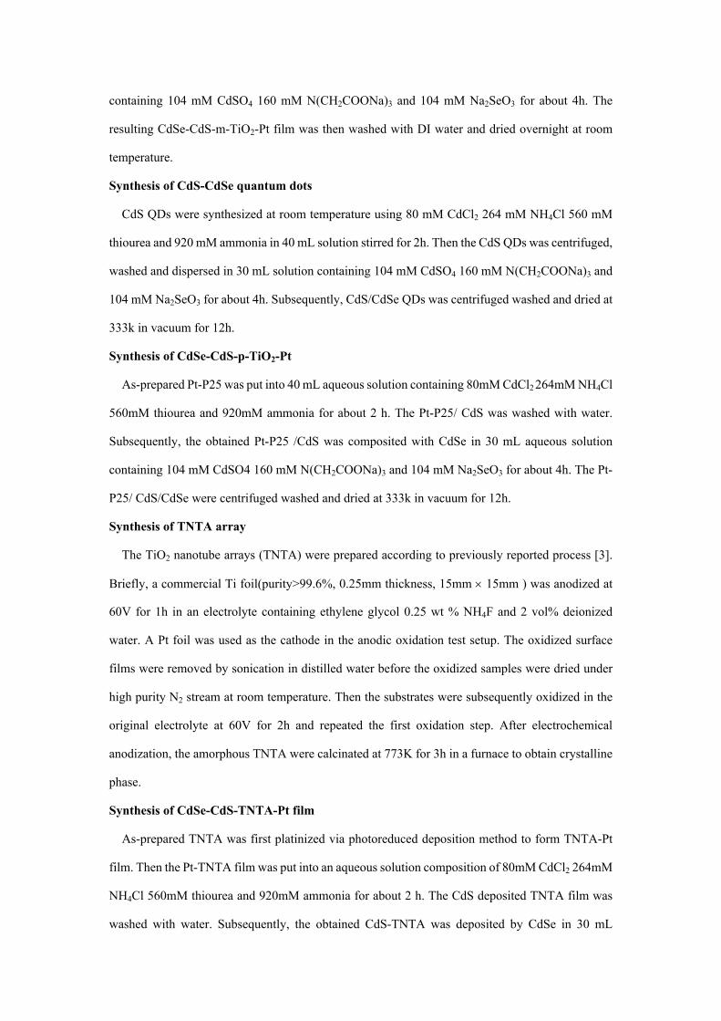
Fabricating efficient CdSe–CdS photocatalyst systems by spatially
resetting water splitting sites
Zhijian Wang,‡ab Junmei Wang,‡ac Li Li,a Jianfeng Zheng,a Suping Jia,a Jiazang Chen,*a Bin Liu*b and Zhenping Zhua
a State Key Laboratory of Coal Conversion, Institute of Coal Chemistry, Chinese Academy of Sciences, Taiyuan, 030001, China.*E-mail: [email protected] School of Chemical and Biomedical Engineering, Nanyang Technological University, Singapore, 637459. *E-mail: [email protected] University of Chinese Academy of Sciences, Beijing, 100049, P. R. China.‡ The two authors contribute the same.
Experimental section
Materials
TiO2(Degussa) Chloroplatinic acid hexahydrate (H2PtCl6·6H2O, Pt basis 10mg/ mL) CdCl2,
CdSO4, N(CH2COONa)3, Se, NH3·H2O, NH4Cl, NH2CSNH2, FTO/glass substrates (12Ω/sq). A
standard Pt-P25 paste was prepared by adding 0.1 g Pt-P25 powder (with diameter of 20nm) into 2
mL isopropanol with stirring for 2days to form homogeneous slurry.
Synthesis of TiO2-Pt
The platinized 2% TiO2-Pt was synthesized by photoreduced deposition method. The procedure
was carried out by dispersing 2g TiO2 in 200 mL methanolic solution containing H2PtCl6·6H2O
(equal to 4 mg Pt) under irradiation of 300 W Hg lamp for 1 h. The TiO2-Pt was collected as powder.
Synthesis of FTO/ TiO2-Pt film
The FTO/TiO2-Pt film were prepared by coating the TiO2-Pt paste onto the cleaned FTO
substrate(1.5cm 1.5cm) using a spin coating method, the TiO2-Pt coated FTO was dried for several
minutes at room temperature and then sintered at 450 for 30min in air according to a described
procedure [1].
Synthesis of CdSe-CdS-m-TiO2-Pt film
CdS and CdSe QDs were assembled onto TiO2-Pt film in sequence by chemical bath
deposition(CBD) method as described in a previous paper[2].The deposition experiment were
carried out using 80mM CdCl2 264mM NH4Cl 560mM thiourea and 920mM ammonia in 40mL
solution for 2h. Subsequently, after washing with water, putting into 30 mL aqueous solution
Electronic Supplementary Material (ESI) for Journal of Materials Chemistry A.This journal is © The Royal Society of Chemistry 2018
containing 104 mM CdSO4 160 mM N(CH2COONa)3 and 104 mM Na2SeO3 for about 4h. The
resulting CdSe-CdS-m-TiO2-Pt film was then washed with DI water and dried overnight at room
temperature.
Synthesis of CdS-CdSe quantum dots
CdS QDs were synthesized at room temperature using 80 mM CdCl2 264 mM NH4Cl 560 mM
thiourea and 920 mM ammonia in 40 mL solution stirred for 2h. Then the CdS QDs was centrifuged,
washed and dispersed in 30 mL solution containing 104 mM CdSO4 160 mM N(CH2COONa)3 and
104 mM Na2SeO3 for about 4h. Subsequently, CdS/CdSe QDs was centrifuged washed and dried at
333k in vacuum for 12h.
Synthesis of CdSe-CdS-p-TiO2-Pt
As-prepared Pt-P25 was put into 40 mL aqueous solution containing 80mM CdCl2 264mM NH4Cl
560mM thiourea and 920mM ammonia for about 2 h. The Pt-P25/ CdS was washed with water.
Subsequently, the obtained Pt-P25 /CdS was composited with CdSe in 30 mL aqueous solution
containing 104 mM CdSO4 160 mM N(CH2COONa)3 and 104 mM Na2SeO3 for about 4h. The Pt-
P25/ CdS/CdSe were centrifuged washed and dried at 333k in vacuum for 12h.
Synthesis of TNTA array
The TiO2 nanotube arrays (TNTA) were prepared according to previously reported process [3].
Briefly, a commercial Ti foil(purity>99.6%, 0.25mm thickness, 15mm 15mm ) was anodized at
60V for 1h in an electrolyte containing ethylene glycol 0.25 wt % NH4F and 2 vol% deionized
water. A Pt foil was used as the cathode in the anodic oxidation test setup. The oxidized surface
films were removed by sonication in distilled water before the oxidized samples were dried under
high purity N2 stream at room temperature. Then the substrates were subsequently oxidized in the
original electrolyte at 60V for 2h and repeated the first oxidation step. After electrochemical
anodization, the amorphous TNTA were calcinated at 773K for 3h in a furnace to obtain crystalline
phase.
Synthesis of CdSe-CdS-TNTA-Pt film
As-prepared TNTA was first platinized via photoreduced deposition method to form TNTA-Pt
film. Then the Pt-TNTA film was put into an aqueous solution composition of 80mM CdCl2 264mM
NH4Cl 560mM thiourea and 920mM ammonia for about 2 h. The CdS deposited TNTA film was
washed with water. Subsequently, the obtained CdS-TNTA was deposited by CdSe in 30 mL
aqueous solution containing 104 mM CdSO4 160 mM N(CH2COONa)3 and 104 mM Na2SeO3 for
about 4h. The CdSe-CdS coated TNTA were cooled to room temperature to obtain the CdSe-CdS-
TNTA hierarchical ordered film.
Synthesis of carbon nanotube array (CNTA)
The vertically aligned multi-walled carbon nanotube array (CNTA) was prepared by chemical
vapor deposition (CVD) method in a quartz tube furnace according to a described procedure [4] .
Typically, a thin Al2O3 film (3nm) and Fe film (2nm) were sputtered on Si/SiO2 substrate
respectively as the catalyst for the growth of CNTs. A gas flow of C2H4 (20sccm), H2 (40sccm), Ar
(100sccm) were carried out as carbon source and carrier gas at 750 oC for 10min.
Synthesis of CdSe-CdS-CNTA-Pt film
CdSe-CdS-CNTA-Pt film were fabricated via the CBD approach resembles the procedure
described in CdSe-CdS-TNTA-Pt film.
Characterization
The microstructure and arrangements of the hybrid materials were investigated using a field-
emission SEM (JEOLJIB-4600F) and High-resolution transmission electron microscopy (JEM-
2100, 200kV). Light absorption properties of the photocatalysts films are evaluated using a UV-vis
spectrometer at room temperature. Photoluminescence recording was performed on a fluorescence
spectrometer (F-7000, Hitachi, Japan).
Photocatalytic measurements
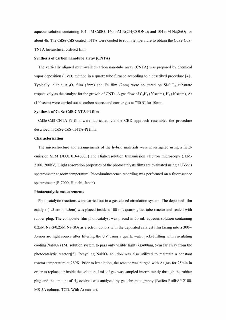
Photocatalytic reactions were carried out in a gas-closed circulation system. The deposited film
catalyst (1.5 cm 1.5cm) was placed inside a 100 mL quartz glass tube reactor and sealed with
rubber plug. The composite film photocatalyst was placed in 50 mL aqueous solution containing
0.25M Na2S/0.25M Na2SO3 as electron donors with the deposited catalyst film facing into a 300w
Xenon arc light source after filtering the UV using a quartz water jacket filling with circulating
cooling NaNO2 (1M) solution system to pass only visible light (λ≥400nm, 5cm far away from the
photocatalytic reactor)[5]. Recycling NaNO2 solution was also utilized to maintain a constant
reactor temperature at 289K. Prior to irradiation, the reactor was purged with Ar gas for 25min in
order to replace air inside the solution. 1mL of gas was sampled intermittently through the rubber
plug and the amount of H2 evolved was analyzed by gas chromatography (Beifen-Ruili:SP-2100.
MS-5A column. TCD. With Ar carrier).
Electrochemical measurements
Photocurrent measurements were performed on an electrochemical workstation(CHI 660D
Shanghai, China) using a standard three-electrode system with prepared samples as working
electrode, a foil as counter electrode and a standard calomel electrode in saturated KCl as reference
electrode.
The electrolyte was an aqueous solution containin 0.25M Na2S and 0.25M Na2SO3. The working
electrode was the photocatalyst without Pt on FTO. Intensity-modulated photocurrent spectroscopy
(IMPS) and photovoltage spectroscopy (IMVS) spectra were recorded on a Zahner IM6ex
electrochemical workstation with a frequency-response analyzer under a 470 nm LED source
supply. The disturbance light intensity was 2% of the base light intensity. The frequency range was
set between 100 kHz and 0.1 Hz.
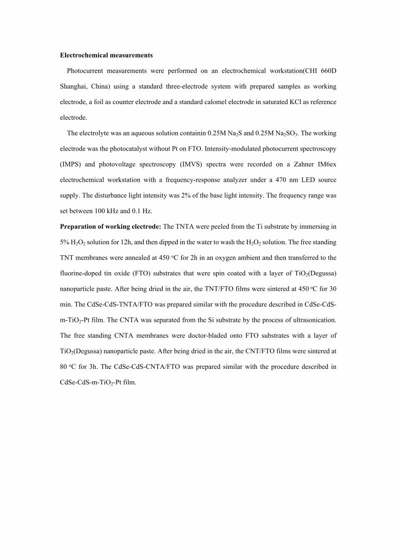
Preparation of working electrode: The TNTA were peeled from the Ti substrate by immersing in
5% H2O2 solution for 12h, and then dipped in the water to wash the H2O2 solution. The free standing
TNT membranes were annealed at 450 oC for 2h in an oxygen ambient and then transferred to the
fluorine-doped tin oxide (FTO) substrates that were spin coated with a layer of TiO2(Degussa)
nanoparticle paste. After being dried in the air, the TNT/FTO films were sintered at 450 oC for 30
min. The CdSe-CdS-TNTA/FTO was prepared similar with the procedure described in CdSe-CdS-
m-TiO2-Pt film. The CNTA was separated from the Si substrate by the process of ultrasonication.
The free standing CNTA membranes were doctor-bladed onto FTO substrates with a layer of
TiO2(Degussa) nanoparticle paste. After being dried in the air, the CNT/FTO films were sintered at
80 oC for 3h. The CdSe-CdS-CNTA/FTO was prepared similar with the procedure described in
CdSe-CdS-m-TiO2-Pt film.
a
b
c
20 40 60 80
CdS-CdSe-m-TiO2-Pt
FTO Glass
Inte
nsity
/ (a
.u.)
2degree
CdS/CdSe
CdS-CdSe-TNTA-Pt
CdS-CdSe-p-TiO2-Pt
d
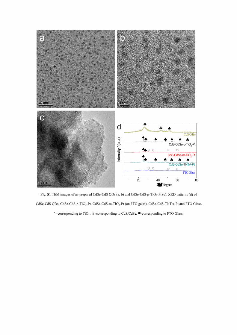
Fig. S1 TEM images of as-prepared CdSe-CdS QDs (a, b) and CdSe-CdS-p-TiO2-Pt (c). XRD patterns (d) of
CdSe-CdS QDs, CdSe-CdS-p-TiO2-Pt, CdSe-CdS-m-TiO2-Pt (on FTO galss), CdSe-CdS-TNTA-Pt and FTO Glass.
ª- corresponding to TiO2, §-corresponding to CdS/CdSe, -corresponding to FTO Glass.
100nm
a
b
c d
fe
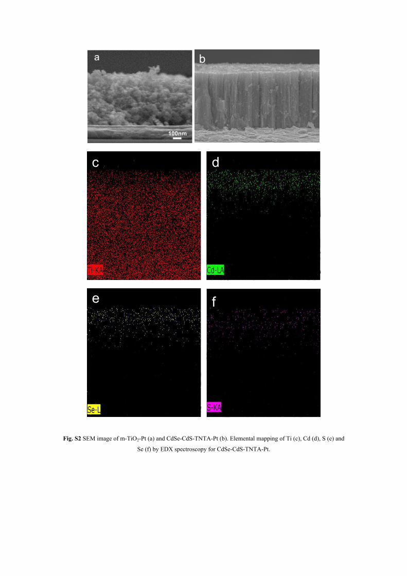
Fig. S2 SEM image of m-TiO2-Pt (a) and CdSe-CdS-TNTA-Pt (b). Elemental mapping of Ti (c), Cd (d), S (e) and
Se (f) by EDX spectroscopy for CdSe-CdS-TNTA-Pt.
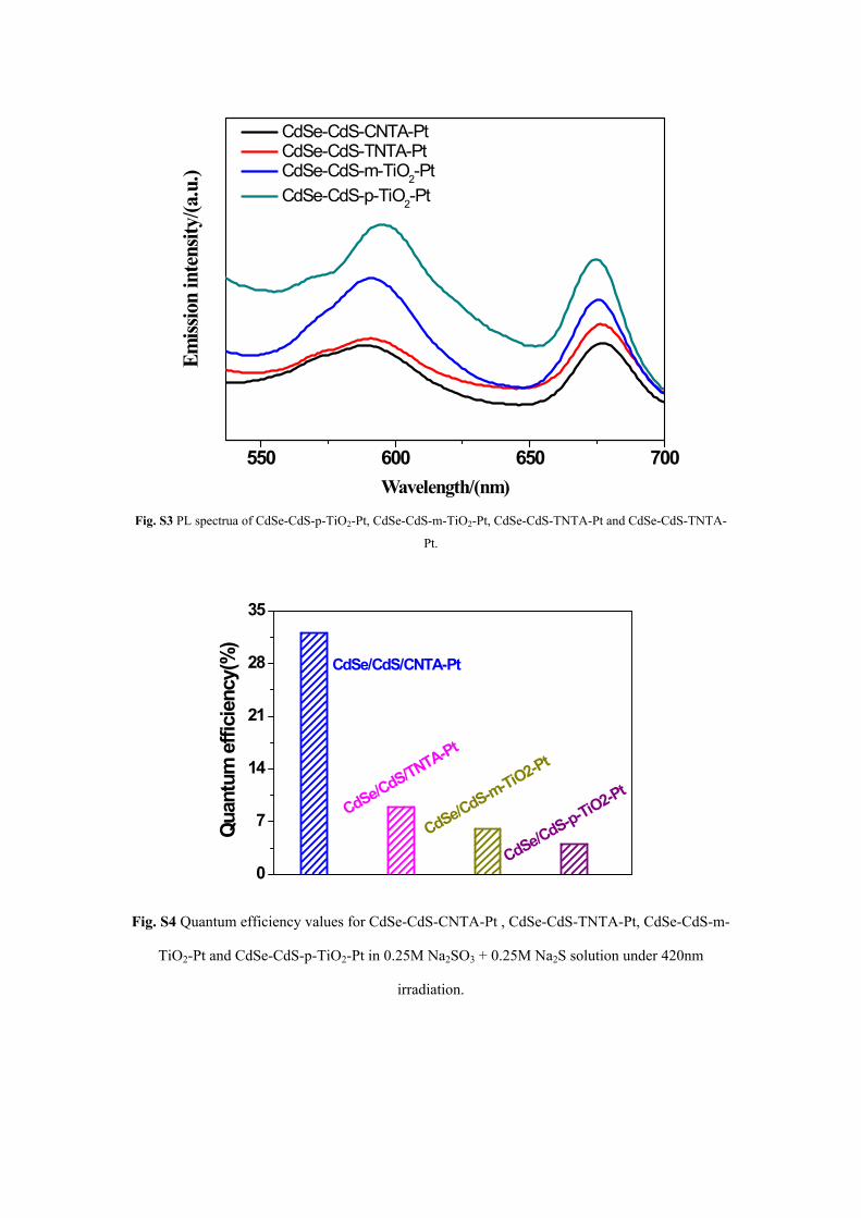
550 600 650 700
Emiss
ion
inte
nsity
/(a.u
.)
Wavelength/(nm)
CdSe-CdS-CNTA-Pt CdSe-CdS-TNTA-Pt CdSe-CdS-m-TiO2-Pt CdSe-CdS-p-TiO2-Pt
Fig. S3 PL spectrua of CdSe-CdS-p-TiO2-Pt, CdSe-CdS-m-TiO2-Pt, CdSe-CdS-TNTA-Pt and CdSe-CdS-TNTA-
Pt.
0
7
14
21
28
35
CdSe/CdS-p-TiO2-Pt
CdSe/CdS-m-TiO2-Pt
CdSe/CdS/TNTA-Pt
CdSe/CdS/CNTA-Pt
Qua
ntum
effi
cien
cy(%
)
Fig. S4 Quantum efficiency values for CdSe-CdS-CNTA-Pt , CdSe-CdS-TNTA-Pt, CdSe-CdS-m-
TiO2-Pt and CdSe-CdS-p-TiO2-Pt in 0.25M Na2SO3 + 0.25M Na2S solution under 420nm
irradiation.
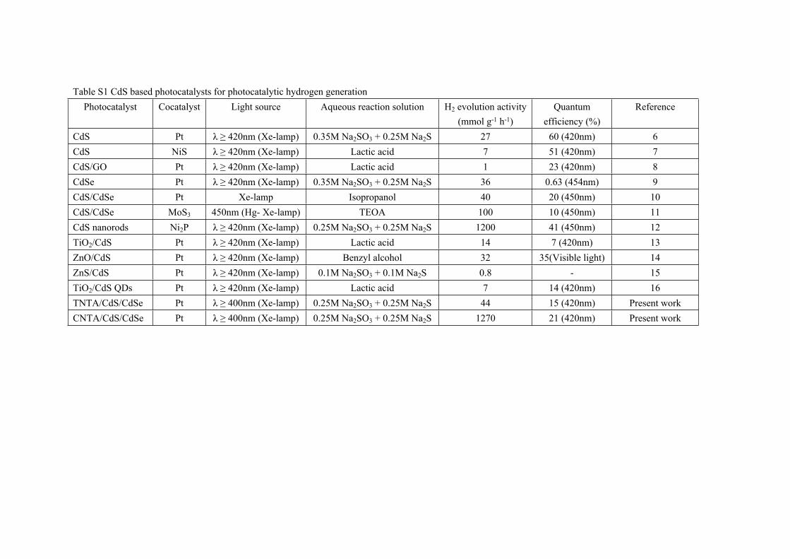
Table S1 CdS based photocatalysts for photocatalytic hydrogen generationPhotocatalyst Cocatalyst Light source Aqueous reaction solution H2 evolution activity
(mmol g-1 h-1)Quantum
efficiency (%)Reference
CdS Pt λ ≥ 420nm (Xe-lamp) 0.35M Na2SO3 + 0.25M Na2S 27 60 (420nm) 6CdS NiS λ ≥ 420nm (Xe-lamp) Lactic acid 7 51 (420nm) 7CdS/GO Pt λ ≥ 420nm (Xe-lamp) Lactic acid 1 23 (420nm) 8CdSe Pt λ ≥ 420nm (Xe-lamp) 0.35M Na2SO3 + 0.25M Na2S 36 0.63 (454nm) 9CdS/CdSe Pt Xe-lamp Isopropanol 40 20 (450nm) 10CdS/CdSe MoS3 450nm (Hg- Xe-lamp) TEOA 100 10 (450nm) 11CdS nanorods Ni2P λ ≥ 420nm (Xe-lamp) 0.25M Na2SO3 + 0.25M Na2S 1200 41 (450nm) 12TiO2/CdS Pt λ ≥ 420nm (Xe-lamp) Lactic acid 14 7 (420nm) 13ZnO/CdS Pt λ ≥ 420nm (Xe-lamp) Benzyl alcohol 32 35(Visible light) 14ZnS/CdS Pt λ ≥ 420nm (Xe-lamp) 0.1M Na2SO3 + 0.1M Na2S 0.8 - 15TiO2/CdS QDs Pt λ ≥ 420nm (Xe-lamp) Lactic acid 7 14 (420nm) 16TNTA/CdS/CdSe Pt λ ≥ 400nm (Xe-lamp) 0.25M Na2SO3 + 0.25M Na2S 44 15 (420nm) Present workCNTA/CdS/CdSe Pt λ ≥ 400nm (Xe-lamp) 0.25M Na2SO3 + 0.25M Na2S 1270 21 (420nm) Present work
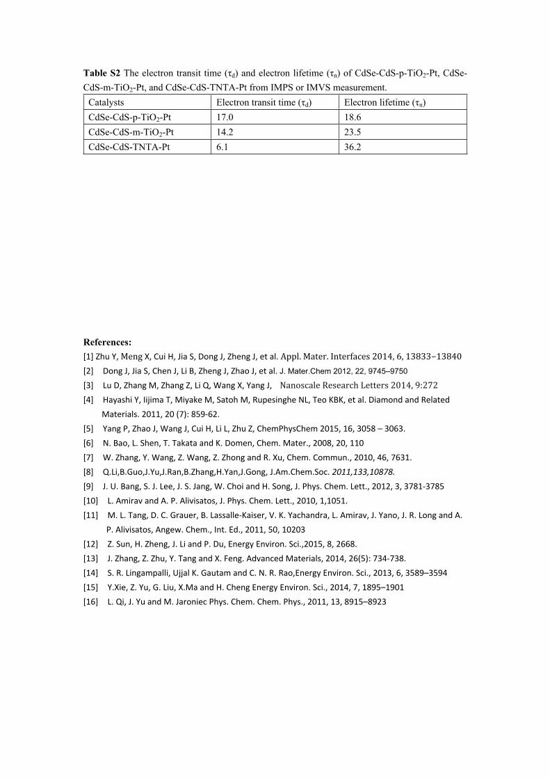
Table S2 The electron transit time (τd) and electron lifetime (τn) of CdSe-CdS-p-TiO2-Pt, CdSe-CdS-m-TiO2-Pt, and CdSe-CdS-TNTA-Pt from IMPS or IMVS measurement.
Catalysts Electron transit time (τd) Electron lifetime (τn)CdSe-CdS-p-TiO2-Pt 17.0 18.6CdSe-CdS-m-TiO2-Pt 14.2 23.5CdSe-CdS-TNTA-Pt 6.1 36.2
References:[1] Zhu Y, Meng X, Cui H, Jia S, Dong J, Zheng J, et al. Appl. Mater. Interfaces 2014, 6, 13833−13840[2] Dong J, Jia S, Chen J, Li B, Zheng J, Zhao J, et al. J. Mater.Chem 2012, 22, 9745–9750
[3] Lu D, Zhang M, Zhang Z, Li Q, Wang X, Yang J, Nanoscale Research Letters 2014, 9:272[4] Hayashi Y, Iijima T, Miyake M, Satoh M, Rupesinghe NL, Teo KBK, et al. Diamond and Related
Materials. 2011, 20 (7): 859-62.[5] Yang P, Zhao J, Wang J, Cui H, Li L, Zhu Z, ChemPhysChem 2015, 16, 3058 – 3063.[6] N. Bao, L. Shen, T. Takata and K. Domen, Chem. Mater., 2008, 20, 110 [7] W. Zhang, Y. Wang, Z. Wang, Z. Zhong and R. Xu, Chem. Commun., 2010, 46, 7631.[8] Q.Li,B.Guo,J.Yu,J.Ran,B.Zhang,H.Yan,J.Gong, J.Am.Chem.Soc. 2011,133,10878. [9] J. U. Bang, S. J. Lee, J. S. Jang, W. Choi and H. Song, J. Phys. Chem. Lett., 2012, 3, 3781-3785 [10] L. Amirav and A. P. Alivisatos, J. Phys. Chem. Lett., 2010, 1,1051. [11] M. L. Tang, D. C. Grauer, B. Lassalle-Kaiser, V. K. Yachandra, L. Amirav, J. Yano, J. R. Long and A.
P. Alivisatos, Angew. Chem., Int. Ed., 2011, 50, 10203[12] Z. Sun, H. Zheng, J. Li and P. Du, Energy Environ. Sci.,2015, 8, 2668.[13] J. Zhang, Z. Zhu, Y. Tang and X. Feng. Advanced Materials, 2014, 26(5): 734-738.[14] S. R. Lingampalli, Ujjal K. Gautam and C. N. R. Rao,Energy Environ. Sci., 2013, 6, 3589–3594[15] Y.Xie, Z. Yu, G. Liu, X.Ma and H. Cheng Energy Environ. Sci., 2014, 7, 1895–1901[16] L. Qi, J. Yu and M. Jaroniec Phys. Chem. Chem. Phys., 2011, 13, 8915–8923