Embed Size (px)
Citation preview
MECHANISM AS SUPPLIED
WWW.FUTUREAUTOMATION.NET
CHR4-RES
TECHNICAL SHEETISSUE 007
SHEET 1
RESIDENTIAL CEILING HINGE RANGE
UK +44 (0) 1438 833577 US +1 (603) 742 9181
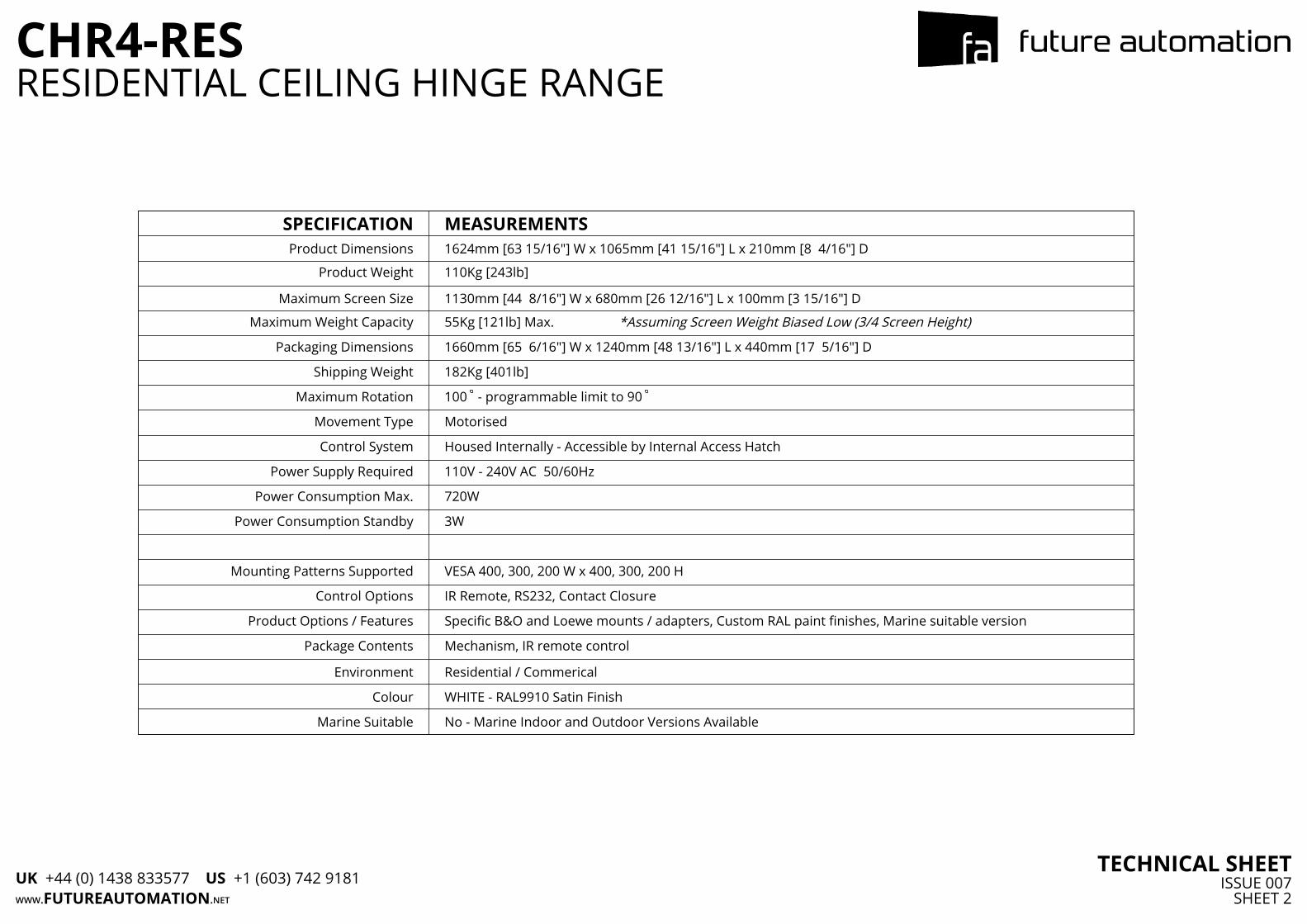
SPECIFICATION MEASUREMENTSProduct Dimensions 1624mm [63 15/16"] W x 1065mm [41 15/16"] L x 210mm [8 4/16"] D
Product Weight 110Kg [243lb]
Maximum Screen Size 1130mm [44 8/16"] W x 680mm [26 12/16"] L x 100mm [3 15/16"] D
Maximum Weight Capacity 55Kg [121lb] Max. *Assuming Screen Weight Biased Low (3/4 Screen Height)
Packaging Dimensions 1660mm [65 6/16"] W x 1240mm [48 13/16"] L x 440mm [17 5/16"] D
Shipping Weight 182Kg [401lb]
Maximum Rotation 100 - programmable limit to 90
Movement Type Motorised
Control System Housed Internally - Accessible by Internal Access Hatch
Power Supply Required 110V - 240V AC 50/60Hz
Power Consumption Max. 720W
Power Consumption Standby 3W
Mounting Patterns Supported VESA 400, 300, 200 W x 400, 300, 200 H
Control Options IR Remote, RS232, Contact Closure
Product Options / Features Specific B&O and Loewe mounts / adapters, Custom RAL paint finishes, Marine suitable version
Package Contents Mechanism, IR remote control
Environment Residential / Commerical
Colour WHITE - RAL9910 Satin Finish
Marine Suitable No - Marine Indoor and Outdoor Versions Available
WWW.FUTUREAUTOMATION.NET
CHR4-RES
TECHNICAL SHEETISSUE 007
SHEET 2
RESIDENTIAL CEILING HINGE RANGE
UK +44 (0) 1438 833577 US +1 (603) 742 9181
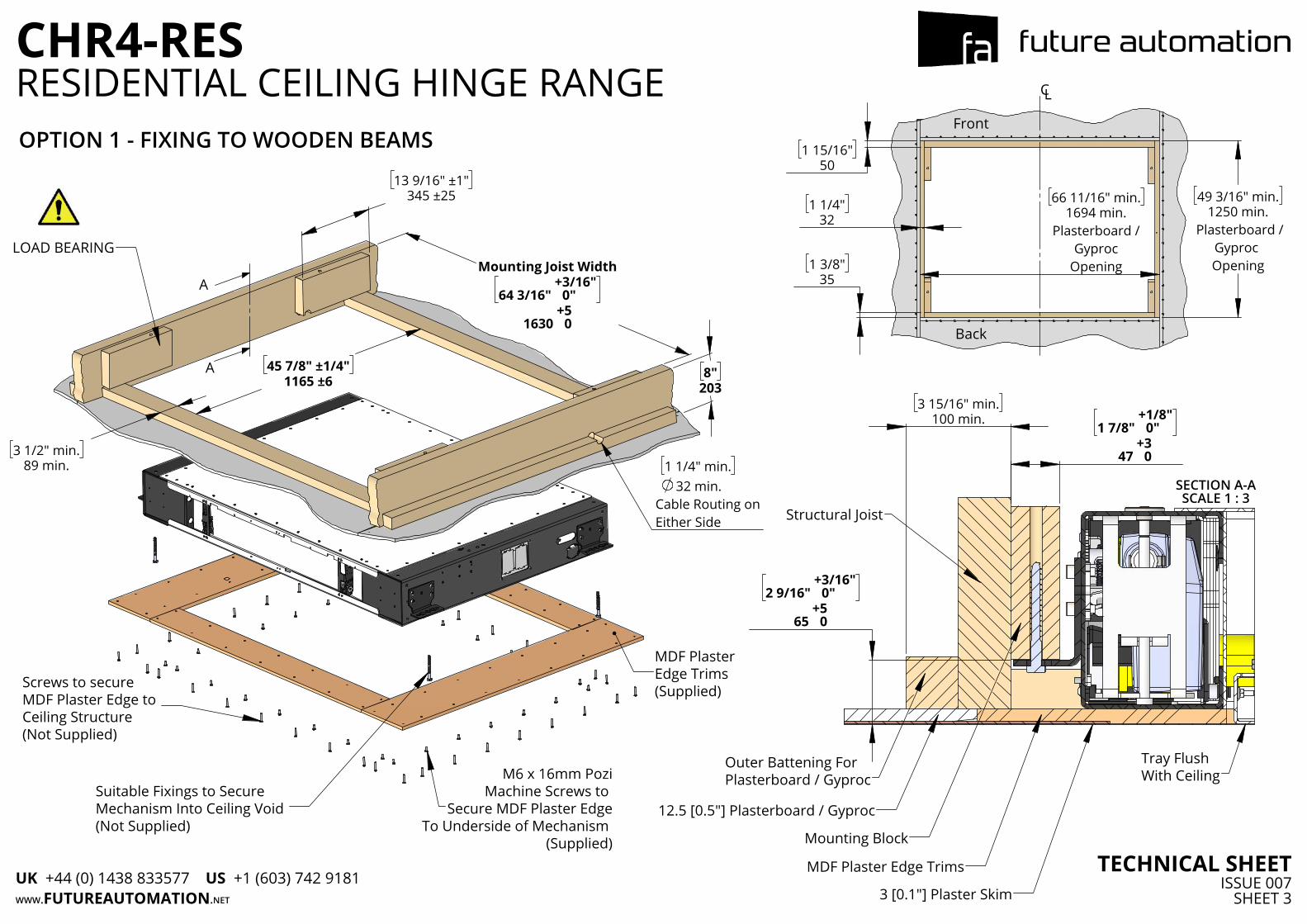
13 9/16" ±1"
345 ±25
Mounting Joist Width
64 3/16" + 3/16"0"
1630 + 50
45 7/8" ±1/4"
1165 ±6
3 1/2" min.
89 min.
1 1/4" min.32 min.
Cable Routing on Either Side
8"
203
Screws to secure MDF Plaster Edge to Ceiling Structure(Not Supplied)
M6 x 16mm PoziMachine Screws to
Secure MDF Plaster EdgeTo Underside of Mechanism
(Supplied)
MDF Plaster Edge Trims (Supplied)
Suitable Fixings to Secure Mechanism Into Ceiling Void (Not Supplied)
LOAD BEARING
A
A
66 11/16" min.1694 min.
Plasterboard /Gyproc
Opening
49 3/16" min.1250 min.
Plasterboard /Gyproc Opening
1 15/16"
50
1 1/4"
32
1 3/8"
35
CL
Front
Back
1 7/8" + 1/8"0"
47 + 30
3 15/16" min.
100 min.
2 9/16" + 3/16"0"
65 + 50
SECTION A-ASCALE 1 : 3
Structural Joist
Outer Battening For Plasterboard / Gyproc
12.5 [0.5"] Plasterboard / Gyproc
Mounting Block
MDF Plaster Edge Trims
3 [0.1"] Plaster Skim
Tray Flush With Ceiling
OPTION 1 - FIXING TO WOODEN BEAMS
WWW.FUTUREAUTOMATION.NET
CHR4-RES
TECHNICAL SHEETISSUE 007
SHEET 3
RESIDENTIAL CEILING HINGE RANGE
UK +44 (0) 1438 833577 US +1 (603) 742 9181
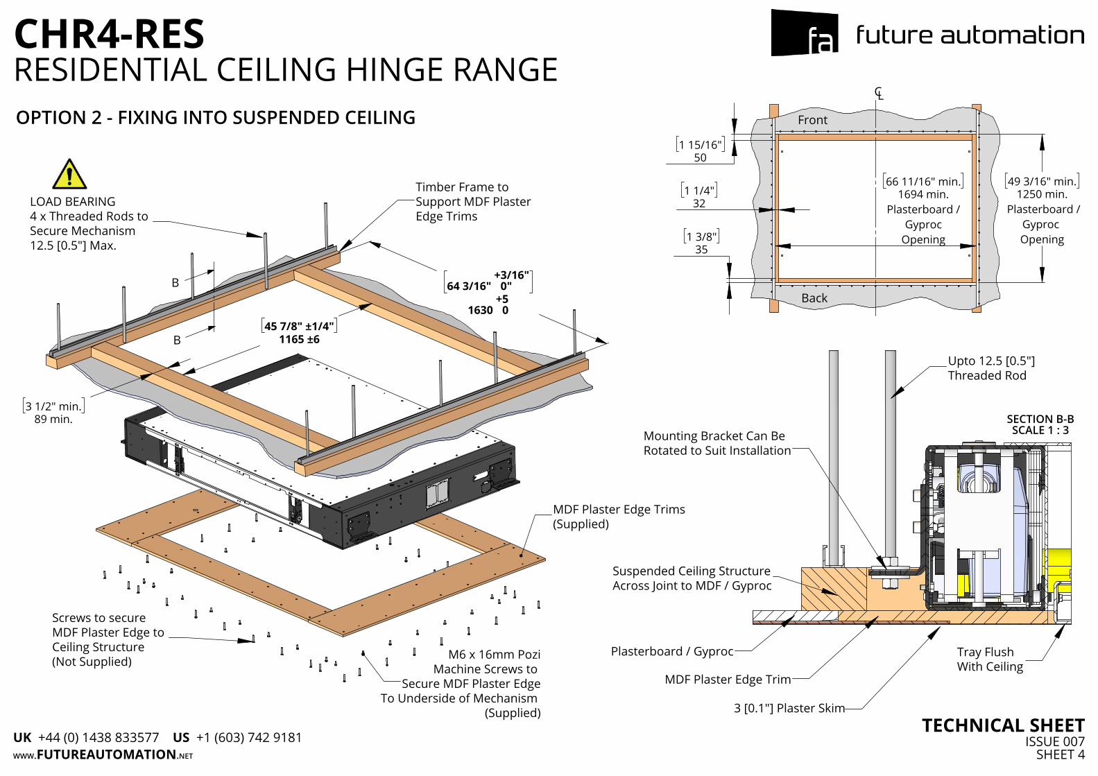
45 7/8" ±1/4"
1165 ±6
64 3/16" + 3/16"0"
1630 + 50
3 1/2" min.
89 min.
Screws to secure MDF Plaster Edge to Ceiling Structure(Not Supplied) M6 x 16mm Pozi
Machine Screws to Secure MDF Plaster Edge
To Underside of Mechanism (Supplied)
MDF Plaster Edge Trims (Supplied)
B
B
LOAD BEARING4 x Threaded Rods to Secure Mechanism12.5 [0.5"] Max.
Timber Frame toSupport MDF PlasterEdge Trims
66 11/16" min.1694 min.
Plasterboard /Gyproc
Opening
49 3/16" min.1250 min.
Plasterboard /Gyproc Opening
1 15/16"
50
1 1/4"
32
1 3/8"
35
CL
Front
Back
SECTION B-BSCALE 1 : 3Mounting Bracket Can Be
Rotated to Suit Installation
Suspended Ceiling StructureAcross Joint to MDF / Gyproc
Plasterboard / Gyproc
MDF Plaster Edge Trim
Upto 12.5 [0.5"]Threaded Rod
Tray Flush With Ceiling
OPTION 2 - FIXING INTO SUSPENDED CEILING
3 [0.1"] Plaster Skim
WWW.FUTUREAUTOMATION.NET
CHR4-RES
TECHNICAL SHEETISSUE 007
SHEET 4
RESIDENTIAL CEILING HINGE RANGE
UK +44 (0) 1438 833577 US +1 (603) 742 9181
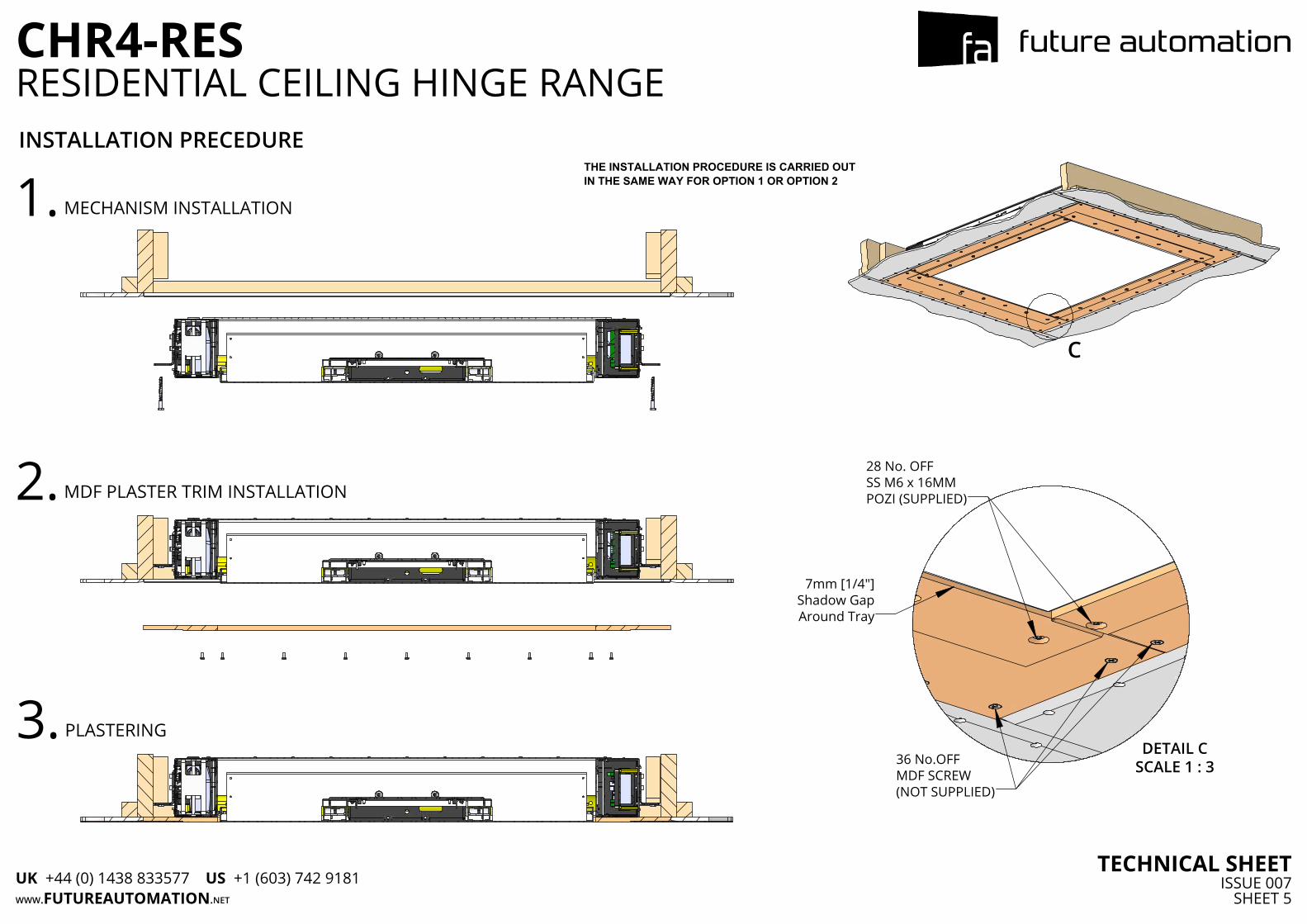
C
DETAIL CSCALE 1 : 3
28 No. OFFSS M6 x 16MMPOZI (SUPPLIED)
36 No.OFFMDF SCREW(NOT SUPPLIED)
7mm [1/4"]Shadow GapAround Tray
INSTALLATION PRECEDURE
1. MECHANISM INSTALLATION
2. MDF PLASTER TRIM INSTALLATION
3. PLASTERING
THE INSTALLATION PROCEDURE IS CARRIED OUTIN THE SAME WAY FOR OPTION 1 OR OPTION 2
WWW.FUTUREAUTOMATION.NET
CHR4-RES
TECHNICAL SHEETISSUE 007
SHEET 5
RESIDENTIAL CEILING HINGE RANGE
UK +44 (0) 1438 833577 US +1 (603) 742 9181
62"
1575
34 7/16"
875
D
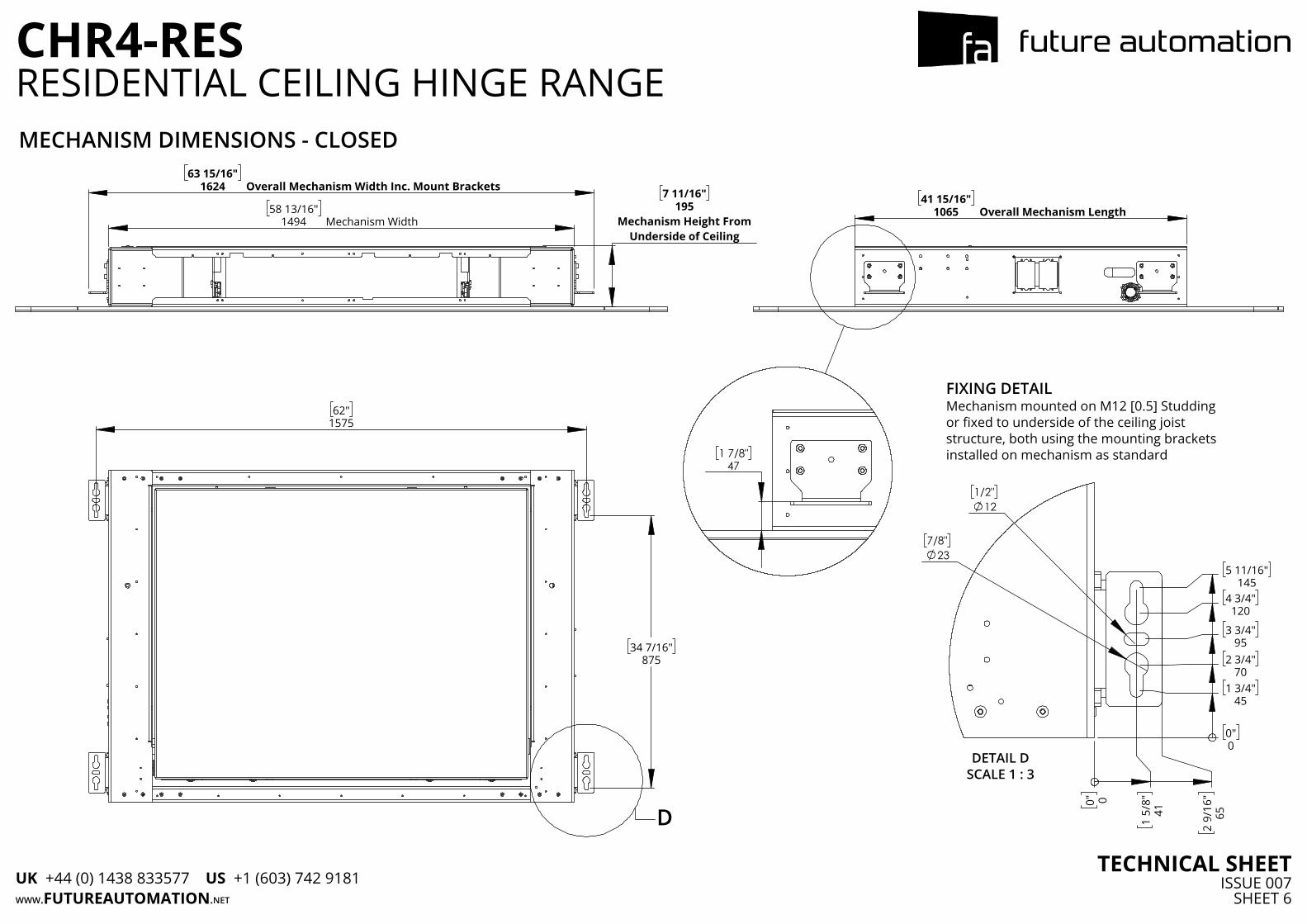
63 15/16"1624 Overall Mechanism Width Inc. Mount Brackets
58 13/16"1494 Mechanism Width
7 11/16"195
Mechanism Height FromUnderside of Ceiling
41 15/16"1065 Overall Mechanism Length
1/2"12
7/8"23
0"0
5 11/16"
145
4 3/4"120
3 3/4"
95
2 3/4"
70
1 3/4"
45
0" 0
1
5/8"
41
2
9/16
"65
DETAIL DSCALE 1 : 3
FIXING DETAILMechanism mounted on M12 [0.5] Studdingor fixed to underside of the ceiling joiststructure, both using the mounting bracketsinstalled on mechanism as standard
1 7/8"
47
MECHANISM DIMENSIONS - CLOSED
WWW.FUTUREAUTOMATION.NET
CHR4-RES
TECHNICAL SHEETISSUE 007
SHEET 6
RESIDENTIAL CEILING HINGE RANGE
UK +44 (0) 1438 833577 US +1 (603) 742 9181
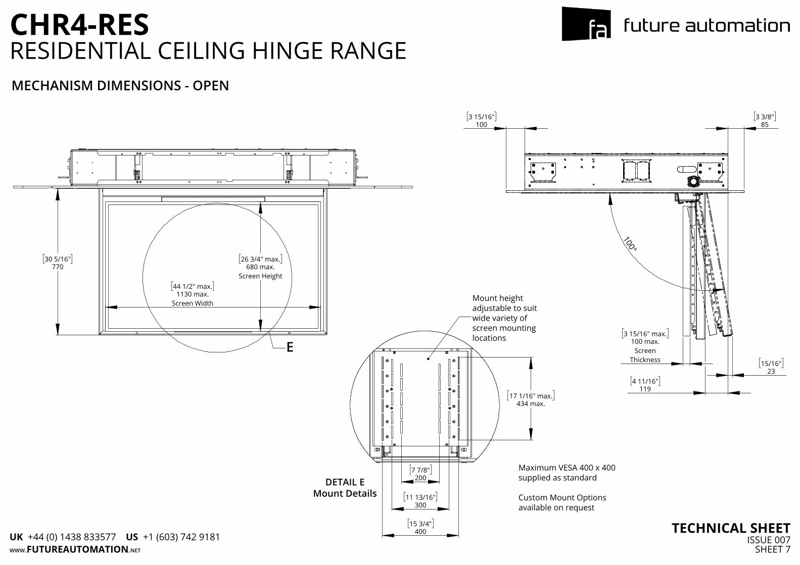
44 1/2" max.1130 max.
Screen Width
26 3/4" max.680 max.
Screen Height
30 5/16"770
E3 15/16" max.
100 max.Screen
Thickness
3 15/16"
100 3 3/8"
85
15/16"
23
4 11/16"
119
100°
Maximum VESA 400 x 400 supplied as standard
Custom Mount Options available on request
7 7/8"200
11 13/16"
300
15 3/4"
400
17 1/16" max.
434 max.
DETAIL EMount Details
Mount heightadjustable to suitwide variety ofscreen mountinglocations
MECHANISM DIMENSIONS - OPEN
WWW.FUTUREAUTOMATION.NET
CHR4-RES
TECHNICAL SHEETISSUE 007
SHEET 7
RESIDENTIAL CEILING HINGE RANGE
UK +44 (0) 1438 833577 US +1 (603) 742 9181
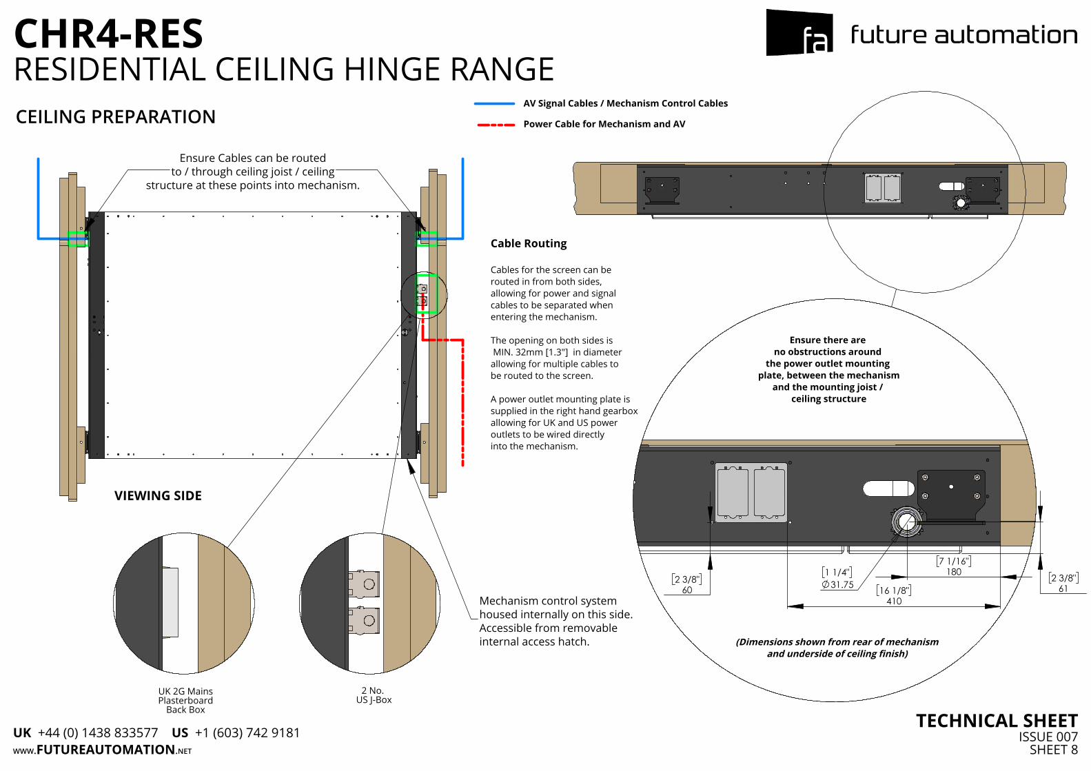
Cable Routing
Cables for the screen can be routed in from both sides, allowing for power and signalcables to be separated when entering the mechanism.
The opening on both sides is MIN. 32mm [1.3"] in diameter allowing for multiple cables to be routed to the screen.
A power outlet mounting plate is supplied in the right hand gearbox allowing for UK and US power outlets to be wired directly into the mechanism.
Ensure Cables can be routedto / through ceiling joist / ceiling
structure at these points into mechanism.
Mechanism control system housed internally on this side.Accessible from removable internal access hatch.
2 No. US J-Box
UK 2G MainsPlasterboard
Back Box
VIEWING SIDE
2 3/8"
60
1 1/4"31.75
2 3/8"61
7 1/16"
180
16 1/8"
410
Ensure there are no obstructions around
the power outlet mounting plate, between the mechanism
and the mounting joist / ceiling structure
(Dimensions shown from rear of mechanismand underside of ceiling finish)
CEILING PREPARATIONAV Signal Cables / Mechanism Control Cables
Power Cable for Mechanism and AV
WWW.FUTUREAUTOMATION.NET
CHR4-RES
TECHNICAL SHEETISSUE 007
SHEET 8
RESIDENTIAL CEILING HINGE RANGE
UK +44 (0) 1438 833577 US +1 (603) 742 9181