Embed Size (px)
Citation preview

Residential Tornado Safe Room from Commodity Wood Products Impact and Wind Pressure Testing
Robert H. FalkJames J. BridwellC. Adam SenalikMarshall Begel
United States Department of Agriculture
ForestService
Forest ProductsLaboratory
General Technical ReportFPL–GTR–254
February2018

Abstract A tornado safe room is a shelter designed to provide protection during a tornado and is specifically engineered to resist the high wind pressures and debris impact generated by these high wind events. The required performance criteria of these shelters has been established and is found in the International Code Council Standard for the Design and Construction of Storm Shelters. A tornado safe room has been developed from commodity wood products and is described in “A Residential Tornado Safe Room from Commodity Wood Products: Design and Development”. In designing this structure, several objectives were pursued: (1) as much as possible, materials available from local building material outlets and online sources should be used, (2) the structure should be buildable by a local contractor or an advanced do-it-yourselfer, (3) retrofitting the structure into an existing home should bepossible, and (4) costs should be kept down by minimizing the useof specialty materials and hardware. Presented here are the resultsof impact and wind pressure testing of the developed wood saferoom design performed according to the requirements of theICC/NSSA-500 standard. Impact testing indicated that the saferoom can resist the most severe impact tests (100-mi/h missilespeed) dictated by ICC/NSSA-500. Also, lateral and uplift loadtesting indicated that the safe room can resist pressures from a250-mi/h wind calculated from wind load design criteria.
Keywords: impact testing, tornado safe room, wood construction
February 2018
Falk, Robert H.; Bridwell, James J.; Senalik, C. Adam; Begel, Marshall. 2018. Residential tornado safe room from commodity wood products: impact and wind pressure testing. FPL–GTR–254. Madison, WI: U.S. Department of Agriculture, Forest Service, Forest Products Laboratory. 19 p.
A limited number of free copies of this publication are available to the public from the Forest Products Laboratory, One Gifford Pinchot Drive, Madison, WI 53726-2398. This publication is also available online at www.fpl.fs.fed.us. Laboratory publications are sent to hundreds of libraries in the United States and elsewhere.
The Forest Products Laboratory is maintained in cooperation with the University of Wisconsin.
The use of trade or firm names in this publication is for reader information and does not imply endorsement by the United States Department of Agriculture (USDA) of any product or service.
In accordance with Federal civil rights law and U.S. Department of Agriculture (USDA) civil rights regulations and policies, the USDA, its Agencies, offices, and employees, and institutions participating in or administering USDA programs are prohibited from discriminating based on race, color, national origin, religion, sex, gender identity (including gender expression), sexual orientation, disability, age, marital status, family/parental status, income derived from a public assistance program, political beliefs, or reprisal or retaliation for prior civil rights activity, in any program or activity conducted or funded by USDA (not all bases apply to all programs). Remedies and complaint filing deadlines vary by program or incident.
Persons with disabilities who require alternative means of communication for program information (e.g., Braille, large print, audiotape, American Sign Language, etc.) should contact the responsible Agency or USDA’s TARGET Center at (202) 720–2600 (voice and TTY) or contact USDA through the Federal Relay Service at (800) 877–8339. Additionally, program information may be made available in languages other than English.
To file a program discrimination complaint, complete the USDA Program Discrimination Complaint Form, AD-3027, found online at http://www.ascr.usda/gov/complaint_filing_cust.html and at any USDA office or write a letter addressed to USDA and provide in the letter all of the information requested in the form. To request a copy of the complaint form, call (866) 632–9992. Submit your completed form or letter to USDA by: (1) mail: U.S. Department of Agriculture, Office of the Assistant Secretary for Civil Rights, 1400 Independence Avenue, SW, Washington, D.C. 20250–9410; (2) fax: (202) 690–7442; or (3) email: [email protected].
USDA is an equal opportunity provider, employer, and lender.
English unit Conversion factor
SI unit
inch (in.) 25.4 millimeter (mm)
foot (ft) 0.3048 meter (m)
square foot (ft2) 0.092903 square meter (m2)
pound (lb), mass 0.45359 kilogram (kg)
pound per square foot (lb/ft2)
47.880 pascal (Pa)
mile per hour (mi/h) 1.609 kilometer per hour (km/h)
Nominal lumber size (in.) Standard lumber size (mm) 2 by 4 38 by 89
2 by 8 38 by 184

Introduction A tornado safe room is a shelter designed to provide protection during a tornado and is specifically engineered to resist the high wind pressures and debris impact generated by these high wind events. The required performance criteria of these shelters has been established and is found in the International Code Council Standard for the Design and Construction of Storm Shelters (ICC/NSSA-500) (ICC/NSSA 2014). The developed wood safe room described in this report was designed to meet the performance criteria of this standard. Several objectives were pursued in the design of the wood tornado safe room: (1) as much as possible, materials available from local building material outlets and online sources should be used, (2) the structure should be buildable by a local contractor or an advanced do-it-yourselfer, (3) retrofitting the structure into an existing home should be possible, and (4) costs should be kept down by minimizing the use of specialty materials and hardware. Details of this design can be found in Falk and Bridwell (2018). This report summarizes the impact and wind pressure test results of both the room components and the full-sized room.
Performance Criteria for Tornado Safe Rooms The performance of a residential tornado safe room has been standardized in ICC/NSSA-500. This standard presents occupancy requirements, impact testing, wind pressure testing, ventilation, and other performance criteria for these structures. This report focuses on impact and wind pressure testing of the tornado safe room and its components.
According to the ICC/NSSA-500 (ICC/NSSA 2014), large missile impact testing is an accepted way of assessing the strength performance of assemblies and materials used in severe weather safe room design. The range of tests is given in Table 1. The tornado test imparts the most energy and thus can be considered the most severe.
In these tests, the safe room was subjected to the impact of a 2 by 4 lumber stud weighing between 15 and 15.5 lb traveling at a speed of 100 mi/h. Paneled or framed walls were impacted in the center of the roof–wall section, at interface joints, or other locations of weakness. A successful impact test requires that the wall meet three basic criteria; (1) permanent wall deflection not greater than 3 in., (2) no creation of significant debris, and (3) no penetration of the missile into the room.
Securing the safe room to the foundation is an important aspect of safe room design, and the tie-down connector, the anchor bolts securing the tie-down connector, and the concrete foundation must have adequate structural strength to resist the forces of the tornado winds. The concrete foundation must have enough thickness and reinforcement to resist anchor bolt pullout, foundation sliding, and overturning.
Wood Safe Room Design and Construction As indicated in Falk and Bridwell (2018), the wood safe room was designed to be 8 by 8 ft in plan with a height of up to 8 ft. This size not only minimizes material waste but
Residential Tornado Safe Room from Commodity Wood Products Impact and Wind Pressure Testing Robert H. Falk, Research Engineer James J. Bridwell, General Engineer C. Adam Senalik, Research General Engineer Marshall Begel, General Engineer USDA Forest Service, Forest Products Laboratory, Madison, Wisconsin
Table 1—Missile testing criteria (TTU 2006)
Test Missile Missile size
(lb)
Missile speed (mi/h)
Basic hurricane 2 by 4 wood stud
9 34
Hurricane enhanced-A 2 by 4 wood stud
15 50
Hurricane enhanced-B 2 by 4 wood stud
15 60
Tornado 2 by 4 wood stud
15 100
Hurricane shelter 2 by 4 wood stud
9 0.4 × wind zone speed

General Technical Report FPL–GTR–254
2
also makes this space suitable for other uses (bathroom, utility room, etc.) when not needed in an emergency.
The walls and roof of the safe room were constructed of stacked and interconnected nail-laminated lumber beams sheathed with plywood. Three 2 by 8s were glued and nailed together to form a beam with a tongue and groove configuration (Fig. 1). The beams were then stacked and interlocked in log cabin fashion to create the walls of the safe room (Fig. 2). Nominal 3/4-in. plywood sheathing was then glued and nailed to the walls and roof to further reinforce the room as well as to tie the walls and roof together (Fig. 3).
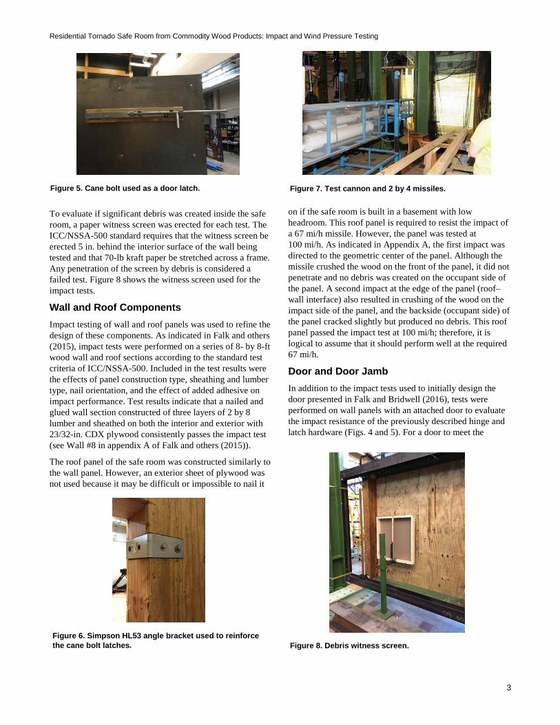
We also developed an overlaid door from plywood and 18-gauge (0.05-in.-thick) steel sheeting. This construction was detailed in Falk and Bridwell (2016). The door was hung with three 3/4-in. gate hinges, similar to that which might be found on a livestock gate (293BC and 294BC, National Hardware LLC, Pinedale, California). These hinges were chosen because of their low cost and adjustability in hanging an overlaid door (Fig. 4). The door was latched from the inside using three cane bolts (Fig. 5) (Product 5000-242, Snug Cottage Hardware Inc., Marysville, Michigan).
In addition, a Simpson Strong-Tie HL53 angle bracket (Simpson Strong-Tie Company, Inc., Pleasanton, California) was used to transfer the concentrated load of each cane bolt
into the tornado safe room wall when the door was subjected to wind suction forces (Fig. 6).
Impact Testing Various components of the safe room, as well as the full-sized room itself, were tested according to the requirements of ICC/NSSA-500 (ICC/NSSA 2014). Some results have been published previously. However, in this report, some of those are presented again to provide continuity to the discussion. New data are also presented. In some cases, tests additional to those required in the standard were performed.
Test Setup and Data Collection The impact tests were performed at the USDA Forest Service, Forest Products Laboratory (FPL) in Madison, Wisconsin, using a modified Mega Launcher II built by Spudtech, LLC (New London, Minnesota) (Fig. 7). The cannon uses compressed air to propel the missile, and the pressure of the compressed air can be adjusted to control the speed of the missile via an external control apparatus. Missile speed was measured using a photoelectric timing device.
As required by the standard, each missile was a surface dry (moisture content between 16% and 19%) wood stud, selected such that no knots appeared within 12 in. of the leading edge. The trailing edge of each missile was affixed with a plastic sabot to facilitate launching.
Figure 1. Nail-laminated 2 by 8 wall beam.
Figure 2. Stacking of wall beams to form walls of safe room.
Figure 3. Safe room with plywood nailed and glued to lumber beams.
Figure 4. Gate bolt hook (left), gate strap hinge (right).
Residential Tornado Safe Room from Commodity Wood Products: Impact and Wind Pressure Testing
3
To evaluate if significant debris was created inside the safe room, a paper witness screen was erected for each test. The ICC/NSSA-500 standard requires that the witness screen be erected 5 in. behind the interior surface of the wall being tested and that 70-lb kraft paper be stretched across a frame. Any penetration of the screen by debris is considered a failed test. Figure 8 shows the witness screen used for the impact tests.
Wall and Roof Components Impact testing of wall and roof panels was used to refine the design of these components. As indicated in Falk and others (2015), impact tests were performed on a series of 8- by 8-ft wood wall and roof sections according to the standard test criteria of ICC/NSSA-500. Included in the test results were the effects of panel construction type, sheathing and lumber type, nail orientation, and the effect of added adhesive on impact performance. Test results indicate that a nailed and glued wall section constructed of three layers of 2 by 8 lumber and sheathed on both the interior and exterior with 23/32-in. CDX plywood consistently passes the impact test (see Wall #8 in appendix A of Falk and others (2015)).
The roof panel of the safe room was constructed similarly to the wall panel. However, an exterior sheet of plywood was not used because it may be difficult or impossible to nail it
on if the safe room is built in a basement with low headroom. This roof panel is required to resist the impact of a 67 mi/h missile. However, the panel was tested at 100 mi/h. As indicated in Appendix A, the first impact was directed to the geometric center of the panel. Although the missile crushed the wood on the front of the panel, it did not penetrate and no debris was created on the occupant side of the panel. A second impact at the edge of the panel (roof–wall interface) also resulted in crushing of the wood on the impact side of the panel, and the backside (occupant side) of the panel cracked slightly but produced no debris. This roof panel passed the impact test at 100 mi/h; therefore, it is logical to assume that it should perform well at the required 67 mi/h.
Door and Door Jamb In addition to the impact tests used to initially design the door presented in Falk and Bridwell (2016), tests were performed on wall panels with an attached door to evaluate the impact resistance of the previously described hinge and latch hardware (Figs. 4 and 5). For a door to meet the
Figure 5. Cane bolt used as a door latch.
Figure 6. Simpson HL53 angle bracket used to reinforce the cane bolt latches.
Figure 7. Test cannon and 2 by 4 missiles.
Figure 8. Debris witness screen.

General Technical Report FPL–GTR–254
4
requirements of ICC/NSSA-500, impact testing is required at several locations. The standard calls for one impact test within 6 in. of the main latch as well as the top hinge and center primary latches or operators. Because there was no center primary latch nor operator, two impact tests were performed to evaluate the hinge and latch impact resistance. As indicated in Figure 9, the first impact was directed at a spot within 6 in. of the upper hinge of the door. The second shot was directed at a spot within 6 in. of the cane bolt latch of the door.
The impact tests resulted in significant dents in the tornado safe room door. However, occupants would have been fully protected because there was no missile penetration, no debris was created, and the door deflected less than 3 in. (Fig. 10 and Appendix B). After impact, the hinge was undamaged and the door opened and closed properly. The second impact test, which was directed at the cane bolt
latch, slightly bent the cane bolt. A hammer was required, albeit with little difficulty, to release the cane bolt out of the door sill in order to open the door.
Impact tests were also performed to evaluate impact resistance of the area around the door perimeter. This is a potential weak area because the 2 by 8 wall beams butt into the door jamb. Also, the door opening itself affects panel strength and stiffness. As shown in Figure 11, a missile was directed at the panel adjacent to the door. Figure 12 and Appendix C indicate the result of this impact. It is clear that the 2 by 8 wall beam to door jamb connection itself is not strong enough to resist the impact of the 2 by 4 missile.
To rectify this problem, three 14-gauge (0.07-in.-thick) sheet steel angles (4 by 4 in.) were fabricated to reinforce the door jamb (Figs. 13 and 14). Initially, these angles were
Figure 9. Impact locations (marked by X).
Figure 10. Door impact damage.
Figure 11. Impact location adjacent to door opening (target is red laser dot midway between the two hinges and slightly to the right).
Figure 12. Damage caused by impact adjacent to door opening. No debris created, but deflection >3 in. occurred.

Residential Tornado Safe Room from Commodity Wood Products: Impact and Wind Pressure Testing
5
secured to the door jamb using a combination of both lag bolts (3/8 by 3 in.) and through bolts (3/8 in.) spaced at 8 in. (Fig. 15).
As indicated in Figure 16 and Appendix C, the impact resistance of the door jambs was greatly improved by the use of the 14-gauge angles. An impact test was also performed above the door and indicated adequate impact resistance of both the head jamb of the door as well as the roof–wall panel connection (Figs. 17 and 18).
Full-Sized Room Tests Several impact tests were performed on the full-sized room to verify the impact resistance of the full-sized structure. Of particular interest were wall–wall intersections, wall–roof intersections, and areas around the sides and top of the door. Because impact tests had already been performed on the center of the wall panels (Falk and Bridwell 2016), the impact tests presented here were focused on panel connections that could not be evaluated without testing the full-sized room. For these tests, the room was anchored to
the strong floor of the test laboratory using eight tie-down anchors (Simpson Strong-Tie HTT5) nailed to the safe room with 16d (3-1/2-in.-long) nails. These anchors were secured using 5/8-in.-diameter Grade 5 bolts to W12x120 steel beams that were clamped to the strong floor of the test laboratory (Figs. 19 and 20).
Figures 21 and 22 indicate the locations of impact on the full-sized room, and Appendix D provides the results for each test. In all cases, the room adequately resisted the missile impact with no debris created, with no piercing of the missile into the room, and with permanent deflection less than 3 in. Impact tests A through F were performed in sequence on the same safe room.
Impact tests A, B, and C evaluated the impact resistance of the wall–roof interface. Impact tests B and C were positioned to concentrate forces not only at the wall–roof interface but also at the wall–wall interface. Impact tests D and F were located specifically to test the butt joint of the
Figure 13. 14-gauge steel angles used to reinforce door frame.
Figure 14. Schematic of door reinforcement angles.
Figure 15. 14-gauge jamb reinforcement. Note use of both lag and through bolts to secure angle.
Figure 16. Effect of using 14-gauge door jamb reinforcement. Note that only slight cracking of the plywood resulted from the impact.

General Technical Report FPL–GTR–254
6
2 by 8 beam at the wall–wall interface (Fig. 2). Although butt connections are not the strongest of wood connections, the butt connections found in these safe room walls were reinforced with 8-in. screws (Gold Star YTX-14800-5, Screw Products, Inc., Gig Harbor, Washington), adhesive (Liquid Nails construction adhesive, PPG Industries, Pittsburgh, Pennsylvania), and the overlapping 23/32-in. plywood sheathing. Most importantly, these connections were reinforced by the interlocking tongue and groove of the 2 by 8 beams, which serves to transfer and dissipate the impact forces.
Although the door and door frame had been previously tested (see Door and Door Jamb section) and this testing indicated the need for sheet metal reinforcement around the door jamb, a final impact test (G) was performed to evaluate the use of lag bolts instead of through bolts for the door reinforcement. As indicated in Appendix D, 3/8- by 3-in. lag bolts at a spacing of 8 in. were adequate to secure the door reinforcement to the door jamb (Fig. 23).
Wind Pressure–Suction–Uplift Tests In addition to resisting the impact loads generated by windblown debris, a tornado safe room must be able to withstand the high wind forces from tornados. The ICC/NSSA-500 standard stipulates that wall, roof, and door assemblies are pressure-tested according to ASTM E330 (ASTM 2014) and ASTM E1886 (ASTM 2013) to simulate the required wind loads. ASTM E330 deals with static testing, and ASTM E1886 describes the methodology for cyclic testing. ASCE/SEI 7-10 (ASCE 2013) is used to calculate wind pressure loads.
Two types of static wind pressure tests were performed to evaluate the components of the safe room as well as the room itself. Cyclic testing was not performed because this room was not specifically designed for hurricane conditions.
Wall–Roof Components A vacuum-based panel test system that will allow static pressure testing of panels according to ASTM E330 loading
Figure 17. Exterior damage caused by impact test of roof–wall interface and head jamb.
Figure 18. Interior damage caused by impact test of head jamb.
Figure 19. Tie-down anchor nailed to safe room and bolted to steel beams that were clamped to test floor.
Figure 20. Tie-down of safe room to strong floor.

Residential Tornado Safe Room from Commodity Wood Products: Impact and Wind Pressure Testing
7
sequence has been developed by PFS Corporation, a building materials test laboratory in Cottage Grove, Wisconsin. As detailed in Falk and Shrestha (2016), this system can be used to exert static pressure on panels up to 8 by 24 ft and can hold pressure to within 1 lb/ft2. This system uses a large vacuum pump connected to a structural frame that is sealed to the laboratory floor. The panel specimen is laid on the steel frame and supported such that a plastic membrane can be laid over the top of the specimen to seal it for testing. A computer controls the vacuum pump and the loading sequence (Fig. 24). According to ICC/NSSA-500, the wall panel shall be loaded to at least 1.2 times the wind load calculated from ASCE 7.
The wall–roof panel tested was asymmetrical in design because it had plywood glued and nailed to only one side. For this reason, the panel was tested twice, once with the plywood on the compression side and once with the plywood on the tension side. Figure 25 shows the test setup for the wall–roof panel. The panel was supported along each bottom edge on a 5.5-in. support beam to simulate the
support provided in a tornado safe room by adjoining walls or a foundation.
The loading and test sequence are detailed in Falk and Shrestha (2016). Results indicated that the panel oriented with the plywood on the tension side withstood the capacity of the test system (568 lb/ft2) and deflected 0.47 in. at the center of the panel. Design pressure for this panel was 225 lb/ft2.
Similar results were found when testing the panel with the plywood on the compression side. However, the maximum load reached was 635 lb/ft2 with a deflection of 0.83 in. As expected, the maximum deflection was at the center of the panel farthest from any support. Again, the test system limited maximum load and the panel did not fail.
These tests indicated that the wall–roof panel exhibited wind pressure resistance well in excess of that required. In the case of the panel with the plywood on the tension side, the load reached was 2.5 times the wind load pressure (and internal suction forces) required by ASCE 7 and
Figure 21. Location of impact tests on safe room (right side and back) (Letters correspond to Column 1 in Appendix D).
Figure 22. Location of impact tests on safe room (left side and front) (Letters correspond to Column 1 in Appendix D).
Figure 23. 3/8- by 3-in. lag bolts to secure door jamb reinforcement to safe room.
Figure 24. Vacuum test system.
General Technical Report FPL–GTR–254
8
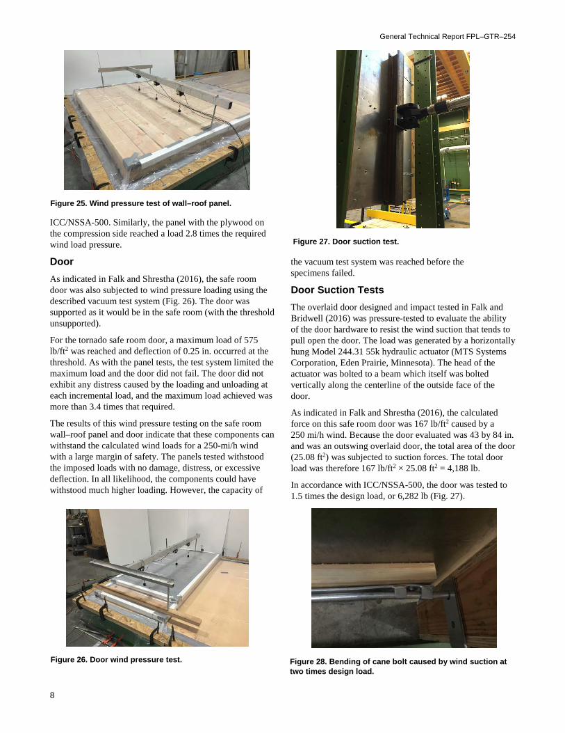
ICC/NSSA-500. Similarly, the panel with the plywood on the compression side reached a load 2.8 times the required wind load pressure.
Door As indicated in Falk and Shrestha (2016), the safe room door was also subjected to wind pressure loading using the described vacuum test system (Fig. 26). The door was supported as it would be in the safe room (with the threshold unsupported).
For the tornado safe room door, a maximum load of 575 lb/ft2 was reached and deflection of 0.25 in. occurred at the threshold. As with the panel tests, the test system limited the maximum load and the door did not fail. The door did not exhibit any distress caused by the loading and unloading at each incremental load, and the maximum load achieved was more than 3.4 times that required.
The results of this wind pressure testing on the safe room wall–roof panel and door indicate that these components can withstand the calculated wind loads for a 250-mi/h wind with a large margin of safety. The panels tested withstood the imposed loads with no damage, distress, or excessive deflection. In all likelihood, the components could have withstood much higher loading. However, the capacity of
the vacuum test system was reached before the specimens failed.
Door Suction Tests The overlaid door designed and impact tested in Falk and Bridwell (2016) was pressure-tested to evaluate the ability of the door hardware to resist the wind suction that tends to pull open the door. The load was generated by a horizontally hung Model 244.31 55k hydraulic actuator (MTS Systems Corporation, Eden Prairie, Minnesota). The head of the actuator was bolted to a beam which itself was bolted vertically along the centerline of the outside face of the door.
As indicated in Falk and Shrestha (2016), the calculated force on this safe room door was 167 lb/ft2 caused by a 250 mi/h wind. Because the door evaluated was 43 by 84 in. and was an outswing overlaid door, the total area of the door (25.08 ft2) was subjected to suction forces. The total door load was therefore 167 lb/ft2 × 25.08 ft2 = 4,188 lb.
In accordance with ICC/NSSA-500, the door was tested to 1.5 times the design load, or 6,282 lb (Fig. 27).
Figure 25. Wind pressure test of wall–roof panel.
Figure 26. Door wind pressure test.
Figure 27. Door suction test.
Figure 28. Bending of cane bolt caused by wind suction at two times design load.

Residential Tornado Safe Room from Commodity Wood Products: Impact and Wind Pressure Testing
9
For the first test, all three cane bolt latches were engaged and the load was ramped to 1.5 times design. For the second test, the center cane bolt latch was disengaged and the door was loaded to 1.5 times design. This was done to see if two latches would adequately resist the wind load suction forces. For the final test, the door was loaded to 2 times design (8,377 lb). For each test, the load was increased across the span of about 1 min to the maximum load and then slowly released.
After the first test, the door was undamaged and there was no cracking or distress witnessed. The three cane bolt latches were operational. After the second test, no damage or distress was witnessed and both cane bolts operated after the test. This indicated that two cane bolts are adequate to secure the safe room door.
In test three, the wind pressure load was increased to 2 times design. Three cane bolts were engaged. After loading, all three cane bolt brackets bent (Fig. 28), making it difficult to retract the cane bolt. Although the door and the hardware resisted this higher level of load and remained intact, a hammer was required to disengage the cane bolts. However, the bolts were easily disengaged with the hammer.
These tests indicate that the tornado safe room door built from plywood and sheet steel and secured with gate hardware can adequately resist the wind suction forces calculated for a 250 mi/h wind with a 1.5 margin of safety and still operate properly. Three door hinges were required as well as two 5/8-in.-diameter cane bolt latches.
Full-Sized Room Tests Lateral wind pressure tests and wind suction uplift tests were also performed on the constructed safe room to evaluate not only the ability of the various components of
the room (wall, roof) to remain intact under wind pressure loads but also to evaluate the ability of the room tie downs to adequately transfer wind pressure loads to the foundation.
The full-sized room was secured to the strong floor of the test laboratory through a series of steel beams as shown in Figure 20. The room was secured to the strong floor adjacent to a reinforced concrete strong wall. An airbag (custom made by MatJack, Indianapolis Industrial Products, Inc., Indianapolis, Indiana) was sandwiched between the safe room and the strong wall to simulate a uniformly applied wind load to the room (Fig. 29). The lateral wind load pressure calculated from ASCE 7 was calculated to be 167 lb/ft2 (appendix A, Falk and Shrestha 2016). This load was applied with pressure delivered through an air regulator (Model QBX, Proportion-Air, Inc., McCordsville, Indiana).
Two tests were performed, the first with the room oriented such that the door was opposite of the airbag and second with the door 90° to the airbag (Fig. 29). These two orientations indicated the effect of the door opening on lateral load resistance.
Air pressure was increased in the air bag, and across a span of about 2 min, the load was increased to a maximum of 2 times design, or 334 lb/ft2. Two upper corners of the room (opposite side from airbag) were fitted with deflection measuring gauges (Celesco PT101, 2 in. full-scale, Celesco Transducer Products, Inc., Chatsworth, California), and deflection was continuously measured throughout the loading sequence using MTS 793 software (Figs. 30 and 31).
When the room was oriented as shown in Figure 30, deflection measurements indicated that the room deflected symmetrically (for example, SP1 = SP2) (SP denotes string pot) up to maximum load (2 times design) (Fig. 32). The maximum deflection recorded was about 1.1 in.
Figure 29. Lateral wind pressure test setup using an airbag. Airbag is orange.
Figure 30. String pot (SP) measuring locations for lateral wind pressure test. Door located opposite air bag.

General Technical Report FPL–GTR–254
10
The room was reoriented as shown in Figure 31 and the test repeated. Because the door opening decreased the stiffness of one side of the room, the room did not deflect symmetrically. As shown in Figure 33, at 2 times design load, the room deflected about 1.8 in. (SP4) and 1.3 in. (SP3).
For both tests at 1.5 times design, the room and its components showed no major damage or distress. Increasing the load to 2 times design resulted in some bending of the tie-downs and some slight nail pullout from the tie-downs (Figs. 34 and 35). This pullout was more pronounced in the test when the room was oriented as in Figure 31.
For both tests, the room itself suffered no distress at 2 times design and all wall–wall and wall–roof connections remained intact. Given this and the fact that the ICC/NSSA-500 does not specify deflection limits for tornado safe
rooms, the authors feel that the deflections measured are acceptable for a load of such high magnitude.
Roof Uplift A Miller series HV2 hydraulic ram (Miller Fluid Power Corporation, Des Plaines, Illinois) was set up inside the safe room, and two steel cross beams (Fig. 36) were used to apply an uplift load to simulate the wind suction forces experienced by the safe room roof. This load tested the adequacy of the wall–roof connection. Deflection of the room was measured using a deflection measuring gauge (Celesco PT101, 2 in. full scale) attached to the geometric center on the external face of the roof. Data were collected using MTS 793 software.
The load was applied and increased to 1.5 times design, or 21,500 lb. There was no distress to the roof, to the roof
Figure 31. String pot (SP) measuring locations for lateral wind pressure test. Door located 90 degrees to air bag.
Figure 32. String pot displacement vs. airbag load pressure test with door opposite to air bag. Deflection of safe room when room oriented as in Figure 30.
Figure 33. String pot displacement vs. airbag load pressure test with door 90 degrees to air bag. Deflection of safe room when room oriented as in Figure 31.
Figure 34. Bending of tie-down at two times design load.

Residential Tornado Safe Room from Commodity Wood Products: Impact and Wind Pressure Testing
11
connection with the walls, nor to the Simpson Strong-Tie HTT5 tie-downs connecting the safe room to the test floor. The roof panel deflected about 0.90 in. at maximum load.
Conclusions A tornado safe room was developed from commodity wood products and is described in “A Residential Tornado Safe Room from Commodity Wood Products: Design and Development” (Falk and Bridwell 2018). Impact testing indicates that the safe room can resist the most severe impact tests (100 mi/h missile speed) dictated by the ICC/NSSA-500 standard. In addition, lateral load and uplift load testing indicated that the safe room can resist wind pressures resulting from a 250 mi/h wind calculated from wind load design criteria (ASCE 2013).
Literature Cited ASCE. 2013. ASCE/SEI 7-10. Minimum design loads for buildings and other structures. Reston, VA: American Society of Civil Engineers. www.pubs.asce.org.
ASTM. 2014. E330/E330M-14. Standard test method for structural performance of exterior windows, doors, skylights and curtain walls by uniform static air pressure difference. West Conshohocken, PA: American Society for Testing and Materials International. www.astm.org.
ASTM. 2013. E1886-13a. Standard test method for performance of exterior windows, curtain walls, doors, and impact protective systems impacted by missile(s) and exposed to cyclic pressure differentials. West Conshohocken, PA: American Society for Testing and Materials International. www.astm.org.
Falk, R.H.; Bridwell, J.J. 2016. Development of a tornado safe room door from wood products: door design and impact testing. Res. Pap. FPL–RP–686. Madison, WI: U.S. Department of Agriculture, Forest Service, Forest Products Laboratory. 17 p.
Falk, R.H.; Bridwell, J.J. 2018. Residential tornado safe room from commodity wood products: design and development. Gen. Tech. Rep. FPL–GTR–253. Madison, WI: U.S. Department of Agriculture, Forest Service, Forest Products Laboratory. 6 p.
Falk, R.H.; Shrestha, D. 2016. Wind pressure testing of tornado safe room components made from wood. Res. Pap. FPL–RP–688. Madison, WI: U.S. Department of Agriculture, Forest Service, Forest Products Laboratory. 6 p.
Falk, R.H.; Bridwell, J.J.; Hermanson, J.C. 2015. Residential tornado safe rooms from commodity wood products: wall development and impact testing. Res. Pap. FPL–RP–681. Madison, WI: U.S. Department of Agriculture, Forest Service, Forest Products Laboratory. 15 p.
ICC/NSSA. 2014. ICC/NSSA-500. Standard for the design and construction of storm shelters. Washington, DC: International Code Council. Lubbock, TX: National Storm Shelter Association.
TTU. 2006. A summary report on debris impact resistance of building assemblies. Lubbock, TX: Texas Tech University. Tallahassee, FL: Florida A&M University. Tallahassee, FL: Florida State University. Gainesville, FL: University of Florida. https://www.depts.ttu.edu/nwi/ research/DebrisImpact/Reports/TTU_Final_NIST_Report_ numbered.pdf.
Figure 35. Nail pullout of tie-down at two times design load.
Figure 36. Hydraulic ram and steel tree to load safe room roof.
General Technical Report FPL–GTR–254
12
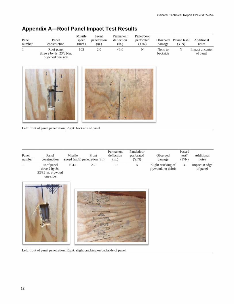
Appendix A—Roof Panel Impact Test Results
Panel number
Panel construction
Missile speed (mi/h)
Front penetration
(in.)
Permanent deflection
(in.)
Panel/door perforated
(Y/N) Observed damage
Passed test? (Y/N)
Additional notes
1 Roof panel three 2 by 8s, 23/32-in.
plywood one side
103 2.0 <1.0 N None to backside
Y Impact at center of panel
Left: front of panel penetration; Right: backside of panel.
Panel number
Panel construction
Missile speed (mi/h)
Front penetration (in.)
Permanent deflection
(in.)
Panel/door perforated
(Y/N) Observed damage
Passed test?
(Y/N) Additional
notes 1 Roof panel
three 2 by 8s, 23/32-in. plywood
one side
104.1 2.2 1.0 N Slight cracking of plywood, no debris
Y Impact at edge of panel
Left: front of panel penetration; Right: slight cracking on backside of panel.
Residential Tornado Safe Room from Commodity Wood Products: Impact and Wind Pressure Testing
13
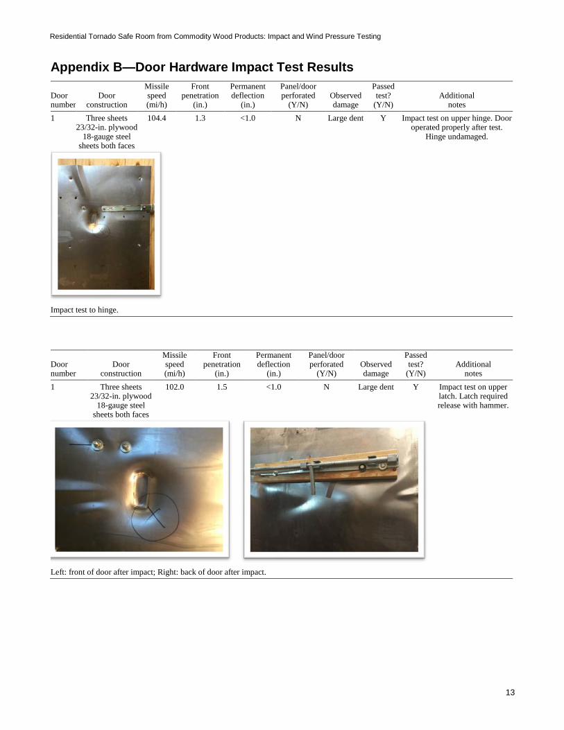
Appendix B—Door Hardware Impact Test Results
Door number
Door construction
Missile speed (mi/h)
Front penetration
(in.)
Permanent deflection
(in.)
Panel/door perforated
(Y/N) Observed damage
Passed test?
(Y/N) Additional
notes 1 Three sheets
23/32-in. plywood 18-gauge steel
sheets both faces
104.4 1.3 <1.0 N Large dent Y Impact test on upper hinge. Door operated properly after test.
Hinge undamaged.
Impact test to hinge.
Door number
Door construction
Missile speed (mi/h)
Front penetration
(in.)
Permanent deflection
(in.)
Panel/door perforated
(Y/N) Observed damage
Passed test?
(Y/N) Additional
notes 1 Three sheets
23/32-in. plywood 18-gauge steel
sheets both faces
102.0 1.5 <1.0 N Large dent Y Impact test on upper latch. Latch required release with hammer.
Left: front of door after impact; Right: back of door after impact.

General Technical Report FPL–GTR–254
14
Appendix C—Door Jamb Impact Test Results
Panel number
Wall construction
Missile speed (mi/h)
Front penetration
(in.)
Permanent deflection
(in.)
Panel/door perforated
(Y/N) Observed damage
Passed test?
(Y/N) Additional
notes 1 2 by 8 beams,
two sheets 23/32-in. plywood
100.3 1.9 4.0 N Excessive deformation
N No debris. Permanent
deformation >3 in.
Left: front of panel before impact test; Center: front of panel after impact test; Right: back of panel after impact test.
Panel number
Wall construction
Missile speed (mi/h)
Front penetration
(in.)
Permanent deflection
(in.)
Panel/door perforated
(Y/N) Observed damage
Passed test?
(Y/N) Additional
notes 1 2 by 8 beams, two sheets
23/32-in. plywood, 14-g steel angle reinforcement around door
100.3 1.5 <1.0 N Slight cracking of plywood
Y No debris
Left: front of panel after impact test; Right: back of panel after impact test.
Residential Tornado Safe Room from Commodity Wood Products: Impact and Wind Pressure Testing
15
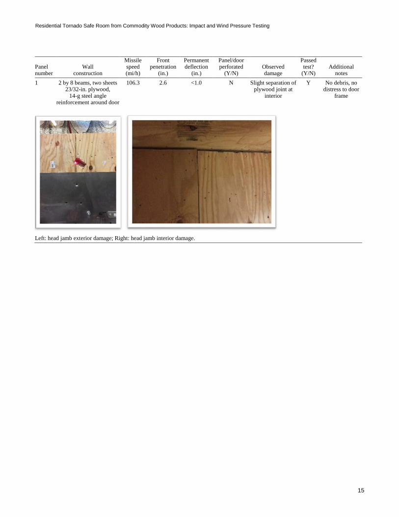
Panel number
Wall construction
Missile speed (mi/h)
Front penetration
(in.)
Permanent deflection
(in.)
Panel/door perforated
(Y/N) Observed damage
Passed test?
(Y/N) Additional
notes 1 2 by 8 beams, two sheets
23/32-in. plywood, 14-g steel angle
reinforcement around door
106.3 2.6 <1.0 N Slight separation of plywood joint at
interior
Y No debris, no distress to door
frame
Left: head jamb exterior damage; Right: head jamb interior damage.
General Technical Report FPL–GTR–254
16
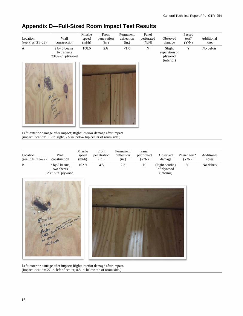
Appendix D—Full-Sized Room Impact Test Results
Location (see Figs. 21–22)
Wall construction
Missile speed (mi/h)
Front penetration
(in.)
Permanent deflection
(in.)
Panel perforated
(Y/N) Observed damage
Passed test?
(Y/N) Additional
notes A
2 by 8 beams, two sheets
23/32-in. plywood
108.6 2.6 <1.0 N Slight separation of
plywood (interior)
Y No debris
Left: exterior damage after impact; Right: interior damage after impact. (impact location: 1.5 in. right, 7.5 in. below top center of room side.)
Location (see Figs. 21–22)
Wall construction
Missile speed (mi/h)
Front penetration
(in.)
Permanent deflection
(in.)
Panel perforated
(Y/N) Observed damage
Passed test? (Y/N)
Additional notes
B 2 by 8 beams, two sheets
23/32-in. plywood
102.9 4.5 2.3 N Slight bending of plywood (interior)
Y No debris
Left: exterior damage after impact; Right: interior damage after impact. (impact location: 27 in. left of center, 8.5 in. below top of room side.)

Residential Tornado Safe Room from Commodity Wood Products: Impact and Wind Pressure Testing
17
Location (see Figs. 21–22)
Wall construction
Missile speed (mi/h)
Front penetration
(in.)
Permanent deflection
(in.)
Panel perforated
(Y/N) Observed damage
Passed test?
(Y/N) Additional
notes C 2 by 8 beams,
two sheets 23/32-in. plywood
107.8 1.9 1.0 N Slight bending of plywood (interior)
Y No debris
Left: exterior damage after impact; Right: interior damage after impact. (impact location: 29 in. left of center, 7 in. below top center of room side.)
Location (see Figs. 21–22)
Wall construction
Missile speed (mi/h)
Front penetration
(in.)
Permanent deflection
(in.)
Panel perforated
(Y/N) Observed damage
Passed test?
(Y/N) Additional
notes D 2 by 8 beams,
two sheets 23/32-in. plywood
103.3 2.4 1.0 N Slight cracking of plywood (interior)
Y No debris
Left: side of room before impact; Right: inside of side of room after impact. (impact location: 30 in. right of center; 22 in. below top of room side.)

General Technical Report FPL–GTR–254
18
Location (see Figs. 21–22)
Wall construction
Missile speed (mi/h)
Front penetration
(in.)
Permanent deflection
(in.)
Panel perforated
(Y/N) Observed damage
Passed test?
(Y/N) Additional
notes E 2 by 8 beams,
two sheets 23/32-in. plywood
106.5 2.5 1.4 N Slight separation of
plywood (interior)
Y No debris
Left: front of room after impact test; Right: back of panel after impact test. (impact location: 32 in. right of center, 16 in. down from top.)
Location (see Figs. 21–22)
Wall construction
Missile speed (mi/h)
Front penetration
(in.)
Permanent deflection
(in.)
Panel perforated
(Y/N) Observed damage
Passed test? (Y/N)
Additional notes
F 2 by 8 beams, two sheets
23/32-in. plywood
103.6 2.5 2.6 N Separation of plywood (interior)
Y No debris. Cumulative
damage from previous test.
Left: front of room after impact test; Right: back of panel after impact test. (impact location: 3 in. right of center, 27.5 in. down from top.)

Residential Tornado Safe Room from Commodity Wood Products: Impact and Wind Pressure Testing
19
Location (see Figs. 21–22)
Wall construction
Missile speed (mi/h)
Front penetration
(in.)
Permanent deflection
(in.)
Panel perforated
(Y/N) Observed damage
Passed test?
(Y/N) Additional
notes G 2 by 8 beams,
two sheets 23/32-in. plywood
104.4 2.3 1.1 N Cracking of plywood (interior)
Y No debris
Left: front of room after impact test; Right: back of panel after impact test. (impact location: 18.5 in. down, 20.5 in. left of top right corner.)