Embed Size (px)
Citation preview

International Journal of Applied Engineering Research ISSN 0973-4562 Volume 13, Number 16 (2018) pp. 12832-12838
© Research India Publications. http://www.ripublication.com
12832
Resistive Lubricant Film Thickness for Ball Bearing 6307 using Design of
Experiment for Elliptical Contact Area between Ball & Races
Ritesh Kumar Dewangan
Associate Professor, Department of Mechanical Engineering, Rungta College of Engineering & Technology, Raipur (C.G.) – 492001, India.
Abstract
Experimental investigation on rolling element bearing with SAE
40 lubricating oil is tested for resistive lubricant film thickness
(RFT). Bearing 6307 is tested for different combination of load
and the speed with the help of Design of experiment (DOE) in
order to save the time and cost of experimentation and also to
determine the effect of each parameter. Result were obtained as
per the planned experiment. The obtained result were analysed
with main effect plot, cube plot and analysis of variance
(ANOVA) using minitab statistical software.
Keywords: Resistance; Complete elliptical integral of second
kind; Design of experiment (DOE); Elliptical contact area;
Elliptical Parameter; General full factorial design; Hertz
contact area; Rolling element bearing; Resistive lubricant film
thickness (RFT); 2-level factorial design.
INTRODUCTION
Rolling element bearings are key element of machineries parts,
whose sudden failure can damage the system to uncorrectable
level. Failure of system can lead to severe economic loss, its
monitoring is very essential to avoid premature failures.
Interferometry, vibration, acoustic emission, ultrasound,
resistance and capacitance are the techniques for monitoring and
diagnose the rolling element bearing, which attracted the
researcher to explore. Observation of lubricant film thickness is
one of the technique to avoid the failure of bearing. Lubricant
film thickness depends upon the load and speed of the shaft on
which the bearing is mounted. Roy Chowdhury [1] proposed a
method for online condition monitoring and control of
hydrodynamic journal bearing using film thickness measurement
such that an adequate film thickness is maintained at all times.
Prasad [2] have used a theoretical approach to determine the
equivalent bearing capacitance, active resistance and impedance
of roller bearing on deformation of races, minimum film
thickness, lubricant characteristics and bearing geometry. Prasad
[3] has observed the effects of operating parameters on the
threshold voltages and impedance response of non-insulated
rolling element bearings under the influence of varying levels of
electrical currents. And established the voltage-current
relationships in the bearings. He has also assessed the film
thickness by the measured impedance and current intensity
response of the bearings. Prasad [4] reports the cause of
generation of localized current in presence of shaft voltage. Also,
it bring out the developed theoretical model to determine the
value of localized current density depending on dimensional
parameters, shaft voltage, contact resistance, frequency of
rotation of shaft and rolling-elements of a bearing. Jie Zhang [5]
described a lubricant film monitoring system for a conventional
deep groove ball bearing using high frequency ultrasonic
transducer mounted in a hole drilled on the static outer raceway
of the bearing. The film thickness is calculated using the
reflection coefficient characterized by lubricant film. Bruce [6]
measured the lubricant-film thickness in a rolling element
bearing using a piezoelectric thin film transducer to excite and
receive ultrasonic signals. High frequency (200 MHz)
ultrasound is generated using a piezoelectric aluminum nitride
film deposited in the form of a very thin layer onto the outer
bearing raceway of a deep groove 6016 ball bearing. The
reflection coefficient from the lubricant layer is then measured
from within the lubricated contact and the oil-film thickness
extracted via a quasi static spring model. M. S. Patil [7] has
studied the influence of defect size, load and speed on the
bearing vibration using Response Surface Methodology (RSM)
using the statistical software MINITAB.
Hertz in 1881 [8] derived an analytical model for concentrated
contact between two isotropic, homogeneous, linear elastic
solids with smooth surfaces. He defined an elliptic parameter k,
the ratio of semi major axis to semi minor axis also given the
formula for minor axis, major axis & equivalent modulus of
elasticity. Harris [9] has given the elliptical para parameter k in
the form of transcendental equation relating the curvature
difference and the elliptic integrals of the first (ℱ) and
second(ℰ ) kinds. Brewe et.al [10] has given the simplified
solution of elliptic contact, elliptic integral of first & second kind
and elliptical contact deformation using the linear regression by
the method of least squares. He found the simplified equations
enable to calculate easily the elliptical-contact deformation to
within 3 percent accuracy. Hamrock and Brewe [11], [12] used a
linear regression by the method of least squares to power fit the
set of pairs of data [(𝑘𝑖 , 𝛼𝑖), 𝑖 = 1, 2, . . . . , 26] and obtained the
simplified solution for elliptical parameter k. Greenwood [13],
[14] compares their ‘Effective radius’ approximate method of
finding the area of contact, the contact pressure and the
deformation in elliptical Hertzian contacts with approximate
methods of Brewe & Hamrock [10], and Hamrock & Brewe
[11]. He concluded for 1 ≤ (𝐵/𝐴) ≤ 5 the Effective Radius
method gives the best value for the Hertz pressure. Nijenbanning
et.al.[15] used the multilevel solver for elliptical contact
problem. He also studied the variations of film thickness with
varying operating conditions and aspect ratio of the contact
ellipse. He has given the formula that predicts the central film
thickness as a function of load and lubricant parameters, and the
International Journal of Applied Engineering Research ISSN 0973-4562 Volume 13, Number 16 (2018) pp. 12832-12838
© Research India Publications. http://www.ripublication.com
12833
ratio of reduced radii of curvature of the surfaces. He concluded
this formula incorporates asymptotic behavior so it is valid for
all load conditions. D Jalali-Vahid et.al. [16] given the numerical
solution of isothermal elastohydrodynamic conjunction for
concentrated contact of elastic bodies under the elliptical point
contact condition. He includes effect of squeeze-film motion that
occurs under transient conditions due to the application of cyclic
loads and/or oscillating motions in machine elements in his
solution. He concluded this time-dependent behavior increases
the load-carrying capacity of the contact which is largely
responsible as a mechanism of lubricant film formation when the
low speeds of entraining motion yield a low film thickness. M.
Kaneta et.al. [17] has discussed the effects of thermal
conductivity and kinematics of contacting surfaces and viscosity
pressure coefficient on the film thickness in an elliptical contact
under pure sliding conditions on the basis of experimental and
numerical results. I. Křupka et.al. [18] has given the
experimental results at high contact stresses and low speeds to
study the thin film behavior. They have observed ultrathin
lubricant films at maximum Hertz pressures of 0.52, 1.01, and
1.54 GPa by using an optical test rig. They have also observed
the nonlinear behavior of both central and minimum film
thicknesses with rolling speed. They concluded slope of the film
thickness decreases at higher speed.
Matharu et. al. [19-24] have developed a new monitoring
technique to measure the Resistive lubricant film thickness of
Rolling Element Bearings. According the Hertz contact theory
[9], [25] when the two isotropic, homogeneous, linear elastic
solids with smooth surfaces solids are pressed together with a
force Q directed normal to the surfaces, an approximately
elliptic contact area is formed. Matharu et. al. [19-24] has
concentrated on studying circular contacts area. However,
elliptical contact area in ball bearings, are likely to be of more
practical importance. So this paper extends the circular model
developed by Matharu et. al. [19-24] to an elliptical geometry. In
this paper the Resistive lubricant film thickness has been
calculated by the analogy given by Matharu et. al. [19-24]
assuming the contact area to be Elliptical. The elliptical contact
area has been calculated here for the bearing 6307 by Hertz
contact theory. Correspondingly the Resistive film thickness has
been calculated for lubricant SAE 40. And the variation of
Resistive lubricant film thickness with load and speed is
analyzed graphically and by 2-level factorial design of Design of
experiment (DOE) [7], [26]. Number of researchers have also
developed the techniques to monitor the lubricant film thickness,
based on some parameters, by various methods [8], [10-16].
Either they are expensive or some major modification was
required on the bearing for proper instrumentation. The present
work uses the technique which is simple & inexpensive [19-24].
Using this inexpensive technique Dewangan et. al. [28-32] has
done the work on resistive lubricant film thickness (RFT) for the
different ball bearings and also calculated the electrical
resistivity of the lubricants.
In the present work bearing 6307 & lubricant SAE 40 is selected
for the experimentation. For the measurement of the RFT, the
experimental setup has been developed. The setup developed is
inexpensive and easier to handle. Two parameters Load and
Speed has been chosen for taking the reading of Voltage Drop
between the ball and race of the bearing. Readings of the
Voltage drop of the lubricant is taken at the Load of 40 kg, 60 kg,
80 kg & 100 kg and at the Speed of 800 rpm, 1000 rpm, 1200
rpm & 1400 rpm. RFT has calculated by Eq.(1). This equation
includes the parameter Contact area of ball & race, Resistivity of
the Lubricant & Bearing Resistance. For Resistivity of the
lubricant separate experiment has been performed and
Resistivity of lubricant SAE 40 has been calculated [24].
Experiment is planned by General full factorial design of Design
of experiment on statistical software Minitab16 to improve the
result. The 2-level factorial design of DOE in the software
Minitab16 is performed to know the significant factors for the
RFT. Normal probability plot, Pareto chart has plotted to know
the significant factors. The p-value also indicates the significant
factors. The Residual plot has plotted to know the data has fitted
by DOE model are correctly or not. The Main Effect Plot and
Interaction Effect Plot has also plotted to know the variation of
RFT with the factors Load, Speed, Volt & Bearing Resistance.
Basic Term
Factors- Factors are the variables used in the experimentation
that influences the response or output.
Level- Level is the specific values for the factors at which the
experiment is performed. The low and high levels of the
factors may be in a coded scale or un-coded scale.
Factorial design- Factorial design is a tool to study the effects
of several factors on a response. The interactions between the
factors can also be studied with the factorial design.
Effect- The change in the response produced by a change in
the level of the factor is called effect.
Resistive Lubricant film thickness (RFT)- It is a indicative
lubricant film thickness formed between the heaviest loaded
ball and race of the ball bearing.
METHODOLOGY
For a ball bearing, the Resistive lubricant film thickness
(RFT) can be estimated by the formula given by Matharu et.
al [19-23] is expressed below.
(ℎ𝑜)𝑇 = 𝑎1𝑎2
(𝑎1 + 𝑎2) 𝑅𝑇
𝜌 (1)
Where,
𝑅𝑇 = 𝑅𝐼𝑅 + 𝑅𝑂𝑅 , 𝑅𝐼𝑅 = 𝜌ℎ𝑜
𝑎1
, 𝑅𝑂𝑅 = 𝜌ℎ𝑜
𝑎2
The contact area between the inner & outer race with the balls
are assuming to be elliptical, which has been calculated by the
formula mentioned below.
International Journal of Applied Engineering Research ISSN 0973-4562 Volume 13, Number 16 (2018) pp. 12832-12838
© Research India Publications. http://www.ripublication.com
12834
Elliptical Area
The elliptical contact area at inner race and outer race for the
calculation of Resistive film thickness can be calculated by
given formula:
𝑎1 = 𝜋 × 𝑎𝑖 × 𝑏𝑖 & 𝑎2 = 𝜋 × 𝑎𝑖 × 𝑏𝑖
where
𝑎𝑖 = [6εQR
πk𝐸′ ]
13
𝑏𝑖 = [6k2εQR
π𝐸′ ]
13
The parameters involved in the above can be calculated as
follows
1
𝑅 =
1
𝑅𝑥+
1
𝑅𝑦
1
𝑅𝑥 =
1
𝑟𝑎𝑥+
1
𝑟𝑏𝑥 &
1
𝑅𝑦 =
1
𝑟𝑎𝑦+
1
𝑟𝑏𝑦
𝜀 = 1 + (𝑞𝑎
𝛼), 𝑞𝑎 = (
𝜋
2) − 1 , 𝛼 =
𝑅𝑦
𝑅𝑥 & 𝑘 = (𝛼)(2 /𝜋)
2
𝐸 ′ = 1 − 𝜈1
2
𝐸1 +
1 − 𝜈22
𝐸2
Bearing Resistance
Bearing Resistance for the calculation of RFT is calculated by
the given formula:
𝐼 = (𝑉𝑖𝑛 − 𝑉) × 1000
𝑅𝑘 & 𝑅𝑇 =
𝑉
𝐼
On the basis of above formula, different parameter for elliptical
area and RFT has been calculated for the Bearing 6307 and
Lubricant SAE 40.
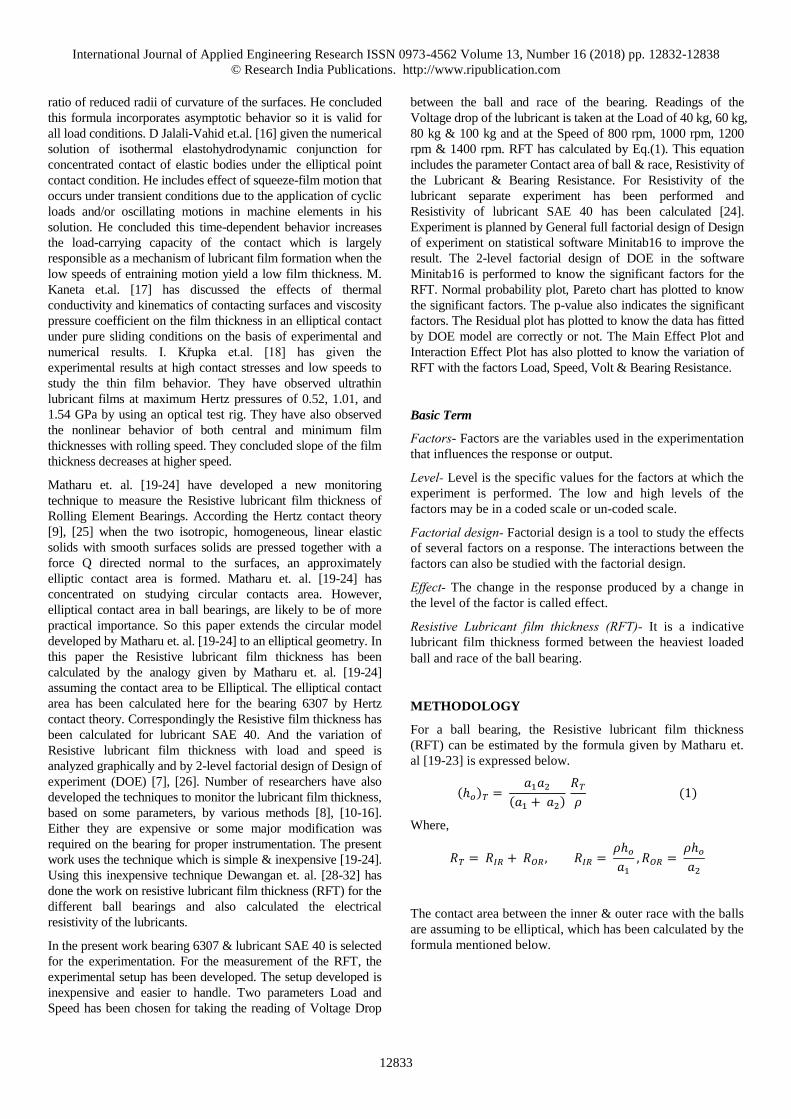
EXPERIMENTAL SETUP
A rolling element test rig is designed and set up to fulfill the
requirements of the current investigation. The schematic of
the test rig is shown in Fig.1. The testing involves mounting
and running the bearing under various speed and load
conditions.
The test rig consists of seven major parts i.e. D.C. Motor,
storage oscilloscope, variable A.C. transformer, regulated
D.C. supply, electrical circuit, spring balance, non conducting
tachometer and supporting shaft with the test bearing. The
operational speed range is up to 1400 rpm and load range is
up to 100 kg. One end of the supporting shaft is supported by
two bearings and is coupled with the D.C. motor through
rectifier and the other end is provided with an arrangement for
radial load to be applied and also for bearings of different
sizes to be attached. Storage oscilloscope, spring balance and
non conducting tachometer are used to take observation while
conducting the test run.
Figure 1: Experimental Setup for Resistive Lubricant Film
Thickness
CALCULATION
Calculation for elliptical contact area is done for the bearing
6307 and then RFR is calculated for lubricant SAE 40. The
calculation is done for Radial Bearing Load 40 kg, 60 kg, 80 kg
& 100 kg at speed 800 rpm, 1000 rpm, 1200 rpm & 1400 rpm of
the bearing. Different parameters for the calculation of RFT
assuming the elliptical contact area is shown in Tab.1.
Table 1: Parameters for calculation of Elliptical Contact Area
PARAMETERS BEARING 6307
INNER RACE OUTER RACE
1/Rx 0.19 0.12
1/Ry 0.0057 0.0057
Rx 5.17 8.33
Ry 175.5 175.5
1/R = (1/Rx)+(1/Ry) 0.1993 0.1257
R 5.02 7.96
α = Ry / Rx 33.98 21.06
k = (α)(2/π) 9.44 6.96
qa=(π/2)-1 0.57 0.57
ε = 1 + (qa / α) 1.02 1.03
E’ (N/mm2) 227363 227363
ANALYSIS & RESULT
Data has been collected by experimentation and reading of
Voltage drop is used for the calculation of the Bearing
Resistance and this is further used to calculate the RFT. Then,
analysis of the data is done in two ways namely:
1. Calculation & Graphical Representation
2. Analysis by Design of Experiment (DOE) [26] by
Statistical Software Minitab16
International Journal of Applied Engineering Research ISSN 0973-4562 Volume 13, Number 16 (2018) pp. 12832-12838
© Research India Publications. http://www.ripublication.com
12835
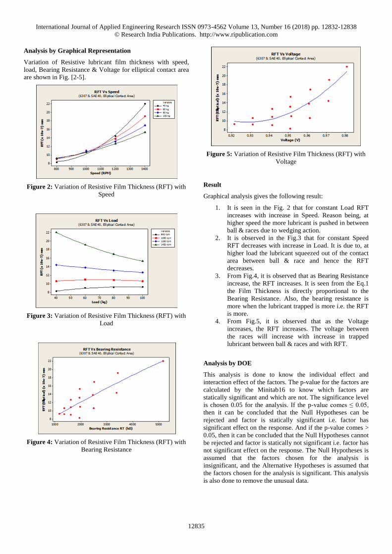
Analysis by Graphical Representation
Variation of Resistive lubricant film thickness with speed,
load, Bearing Resistance & Voltage for elliptical contact area
are shown in Fig. [2-5].
Figure 2: Variation of Resistive Film Thickness (RFT) with
Speed
Figure 3: Variation of Resistive Film Thickness (RFT) with
Load
Figure 4: Variation of Resistive Film Thickness (RFT) with
Bearing Resistance
Figure 5: Variation of Resistive Film Thickness (RFT) with
Voltage
Result
Graphical analysis gives the following result:
1. It is seen in the Fig. 2 that for constant Load RFT
increases with increase in Speed. Reason being, at
higher speed the more lubricant is pushed in between
ball & races due to wedging action.
2. It is observed in the Fig.3 that for constant Speed
RFT decreases with increase in Load. It is due to, at
higher load the lubricant squeezed out of the contact
area between ball & race and hence the RFT
decreases.
3. From Fig.4, it is observed that as Bearing Resistance
increase, the RFT increases. It is seen from the Eq.1
the Film Thickness is directly proportional to the
Bearing Resistance. Also, the bearing resistance is
more when the lubricant trapped is more i.e. the RFT
is more.
4. From Fig.5, it is observed that as the Voltage
increases, the RFT increases. The voltage between
the races will increase with increase in trapped
lubricant between ball & races and with RFT.
Analysis by DOE
This analysis is done to know the individual effect and
interaction effect of the factors. The p-value for the factors are
calculated by the Minitab16 to know which factors are
statically significant and which are not. The significance level
is chosen 0.05 for the analysis. If the p-value comes ≤ 0.05,
then it can be concluded that the Null Hypotheses can be
rejected and factor is statically significant i.e. factor has
significant effect on the response. And if the p-value comes >
0.05, then it can be concluded that the Null Hypotheses cannot
be rejected and factor is statically not significant i.e. factor has
not significant effect on the response. The Null Hypotheses is
assumed that the factors chosen for the analysis is
insignificant, and the Alternative Hypotheses is assumed that
the factors chosen for the analysis is significant. This analysis
is also done to remove the unusual data.
International Journal of Applied Engineering Research ISSN 0973-4562 Volume 13, Number 16 (2018) pp. 12832-12838
© Research India Publications. http://www.ripublication.com
12836
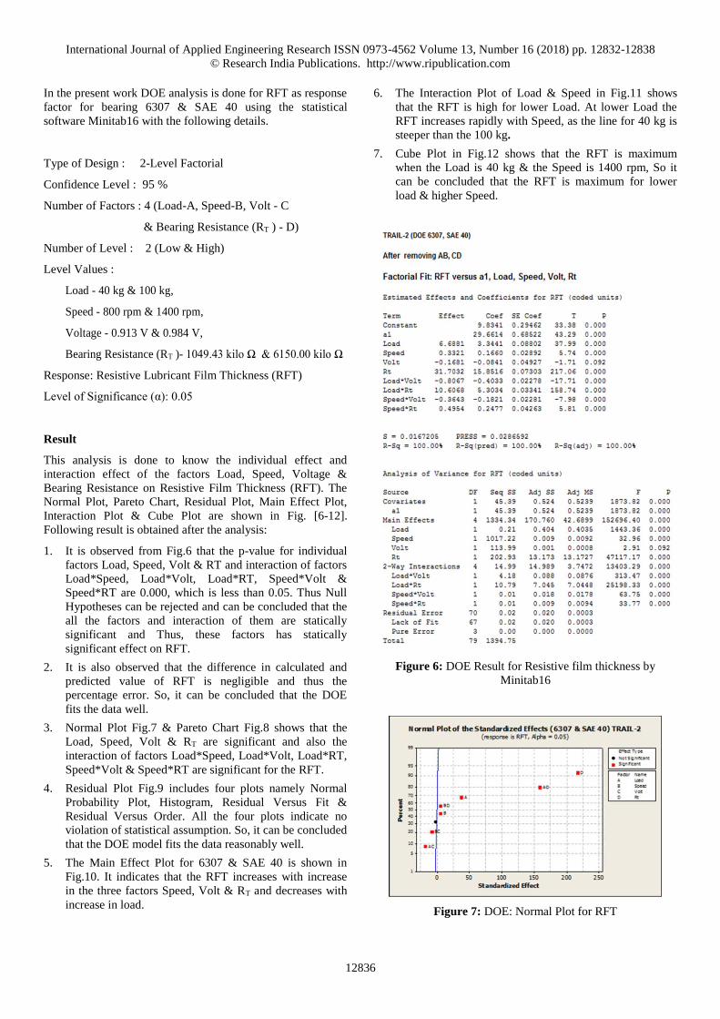
In the present work DOE analysis is done for RFT as response
factor for bearing 6307 & SAE 40 using the statistical
software Minitab16 with the following details.
Type of Design : 2-Level Factorial
Confidence Level : 95 %
Number of Factors : 4 (Load-A, Speed-B, Volt - C
& Bearing Resistance (RT ) - D)
Number of Level : 2 (Low & High)
Level Values :
Load - 40 kg & 100 kg,
Speed - 800 rpm & 1400 rpm,
Voltage - 0.913 V & 0.984 V,
Bearing Resistance (RT )- 1049.43 kilo Ω & 6150.00 kilo Ω
Response: Resistive Lubricant Film Thickness (RFT)
Level of Significance (α): 0.05
Result
This analysis is done to know the individual effect and
interaction effect of the factors Load, Speed, Voltage &
Bearing Resistance on Resistive Film Thickness (RFT). The
Normal Plot, Pareto Chart, Residual Plot, Main Effect Plot,
Interaction Plot & Cube Plot are shown in Fig. [6-12].
Following result is obtained after the analysis:
1. It is observed from Fig.6 that the p-value for individual
factors Load, Speed, Volt & RT and interaction of factors
Load*Speed, Load*Volt, Load*RT, Speed*Volt &
Speed*RT are 0.000, which is less than 0.05. Thus Null
Hypotheses can be rejected and can be concluded that the
all the factors and interaction of them are statically
significant and Thus, these factors has statically
significant effect on RFT.
2. It is also observed that the difference in calculated and
predicted value of RFT is negligible and thus the
percentage error. So, it can be concluded that the DOE
fits the data well.
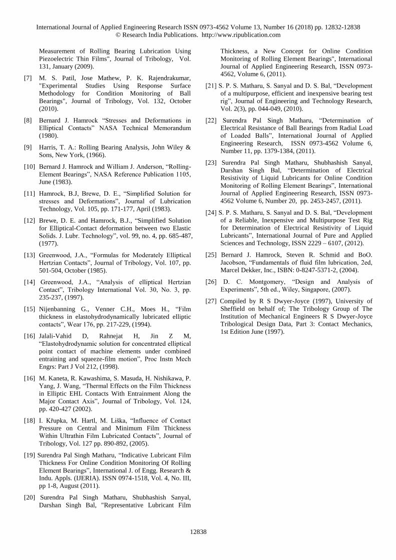
3. Normal Plot Fig.7 & Pareto Chart Fig.8 shows that the
Load, Speed, Volt & RT are significant and also the
interaction of factors Load*Speed, Load*Volt, Load*RT,
Speed*Volt & Speed*RT are significant for the RFT.
4. Residual Plot Fig.9 includes four plots namely Normal
Probability Plot, Histogram, Residual Versus Fit &
Residual Versus Order. All the four plots indicate no
violation of statistical assumption. So, it can be concluded
that the DOE model fits the data reasonably well.
5. The Main Effect Plot for 6307 & SAE 40 is shown in
Fig.10. It indicates that the RFT increases with increase
in the three factors Speed, Volt & RT and decreases with
increase in load.
6. The Interaction Plot of Load & Speed in Fig.11 shows
that the RFT is high for lower Load. At lower Load the
RFT increases rapidly with Speed, as the line for 40 kg is
steeper than the 100 kg.
7. Cube Plot in Fig.12 shows that the RFT is maximum
when the Load is 40 kg & the Speed is 1400 rpm, So it
can be concluded that the RFT is maximum for lower
load & higher Speed.
Figure 6: DOE Result for Resistive film thickness by
Minitab16
Figure 7: DOE: Normal Plot for RFT

International Journal of Applied Engineering Research ISSN 0973-4562 Volume 13, Number 16 (2018) pp. 12832-12838
© Research India Publications. http://www.ripublication.com
12837
Figure 8: DOE: Pareto Chart for RFT
Figure 9: DOE: Residual Plot of RFT
Figure 10: DOE: Main Effect Plot of RFT
Figure 11: DOE: Interaction Plot for RFT
Figure 12: DOE: Cube Plot for RFT
CONCLUSION
Following conclusion are drawn from the present work:
a. The graphical analysis of experimentation yields:
1. The RFT increases with increase in speed for
constant load due to more entrapment of
lubricant owing to wedging action between ball
and races.
2. RFT decreases with increase in load which is
analogous to the results of earlier researchers.
b. The DOE analysis yields:
1. The individual & interaction effect of load,
speed, voltage & bearing resistance were found
to be statically significant for RFT.
2. DOE as an effective tool for analysis of RFT is
thus justified.
REFERENCE
[1] S.K. Roy Chowdhury (2000), “A feedback control
system for plain bearings using film thickness
measurement”, Tribology International, 33, pp. 29-37,
(2000).
[2] Har Prasad, “Theoretical evaluation of impedance,
capacitance and charge accumulation on roller bearing
operated under electrical fields”, Wear, 125, pp. 223-239,
(1988).
[3] Har Prasad H, ”Effect of operating parameters on the
threshold voltages and impedance response of non-
insulated rolling element bearings under the action of
electrical currents”, Wear, 117, pp. 223 – 240 (1987).
[4] Har Prasad, “Diagnosis of Rolling-Element Bearings
Failure by Localized Electrical Current Between Track
Surfaces of Races and Rolling-Elements”, Journal of
Tribology - Transactions of the ASME, pp. 468-473
(2002).
[5] Jie Zhang, Bruce W. Drinkwater, Rob S. Dwyer-Joyce,
"Monitoring of Lubricant Film Failure in a Ball Bearing
Using Ultrasound", Transactions of the ASME, Vol. 128,
pp. 612-618 (2006).
[6] Bruce W. Drinkwater, Jie Zhang, Katherine J. Kirk,
Jocelyn Elgoyhen Rob S. Dwyer-Joyce, "Ultrasonic
International Journal of Applied Engineering Research ISSN 0973-4562 Volume 13, Number 16 (2018) pp. 12832-12838
© Research India Publications. http://www.ripublication.com
12838
Measurement of Rolling Bearing Lubrication Using
Piezoelectric Thin Films", Journal of Tribology, Vol.
131, January (2009).
[7] M. S. Patil, Jose Mathew, P. K. Rajendrakumar,
"Experimental Studies Using Response Surface
Methodology for Condition Monitoring of Ball
Bearings", Journal of Tribology, Vol. 132, October
(2010).
[8] Bernard J. Hamrock “Stresses and Deformations in
Elliptical Contacts” NASA Technical Memorandum
(1980).
[9] Harris, T. A.: Rolling Bearing Analysis, John Wiley &
Sons, New York, (1966).
[10] Bernard J. Hamrock and William J. Anderson, “Rolling-
Element Bearings”, NASA Reference Publication 1105,
June (1983).
[11] Hamrock, B.J, Brewe, D. E., “Simplified Solution for
stresses and Deformations”, Journal of Lubrication
Technology, Vol. 105, pp. 171-177, April (1983).
[12] Brewe, D. E. and Hamrock, B.J., “Simplified Solution
for Elliptical-Contact deformation between two Elastic
Solids. J. Lubr. Technology”, vol. 99, no. 4, pp. 685-487,
(1977).
[13] Greenwood, J.A., “Formulas for Moderately Elliptical
Hertzian Contacts”, Journal of Tribology, Vol. 107, pp.
501-504, October (1985).
[14] Greenwood, J.A., “Analysis of elliptical Hertzian
Contact”, Tribology International Vol. 30, No. 3, pp.
235-237, (1997).
[15] Nijenbanning G., Venner C.H., Moes H., “Film
thickness in elastohydrodynamically lubricated elliptic
contacts”, Wear 176, pp. 217-229, (1994).
[16] Jalali-Vahid D, Rahnejat H, Jin Z M,
“Elastohydrodynamic solution for concentrated elliptical
point contact of machine elements under combined
entraining and squeeze-film motion”, Proc Instn Mech
Engrs: Part J Vol 212, (1998).
[16] M. Kaneta, R. Kawashima, S. Masuda, H. Nishikawa, P.
Yang, J. Wang, “Thermal Effects on the Film Thickness
in Elliptic EHL Contacts With Entrainment Along the
Major Contact Axis”, Journal of Tribology, Vol. 124,
pp. 420-427 (2002).
[18] I. Křupka, M. Hartl, M. Liška, “Influence of Contact
Pressure on Central and Minimum Film Thickness
Within Ultrathin Film Lubricated Contacts”, Journal of
Tribology, Vol. 127 pp. 890-892, (2005).
[19] Surendra Pal Singh Matharu, “Indicative Lubricant Film
Thickness For Online Condition Monitoring Of Rolling
Element Bearings”, International J. of Engg. Research &
Indu. Appls. (IJERIA). ISSN 0974-1518, Vol. 4, No. III,
pp 1-8, August (2011).
[20] Surendra Pal Singh Matharu, Shubhashish Sanyal,
Darshan Singh Bal, "Representative Lubricant Film
Thickness, a New Concept for Online Condition
Monitoring of Rolling Element Bearings", International
Journal of Applied Engineering Research, ISSN 0973-
4562, Volume 6, (2011).
[21] S. P. S. Matharu, S. Sanyal and D. S. Bal, “Development
of a multipurpose, efficient and inexpensive bearing test
rig”, Journal of Engineering and Technology Research,
Vol. 2(3), pp. 044-049, (2010).
[22] Surendra Pal Singh Matharu, “Determination of
Electrical Resistance of Ball Bearings from Radial Load
of Loaded Balls”, International Journal of Applied
Engineering Research, ISSN 0973-4562 Volume 6,
Number 11, pp. 1379-1384, (2011).
[23] Surendra Pal Singh Matharu, Shubhashish Sanyal,
Darshan Singh Bal, “Determination of Electrical
Resistivity of Liquid Lubricants for Online Condition
Monitoring of Rolling Element Bearings”, International
Journal of Applied Engineering Research, ISSN 0973-
4562 Volume 6, Number 20, pp. 2453-2457, (2011).
[24] S. P. S. Matharu, S. Sanyal and D. S. Bal, “Development
of a Reliable, Inexpensive and Multipurpose Test Rig
for Determination of Electrical Resistivity of Liquid
Lubricants”, International Journal of Pure and Applied
Sciences and Technology, ISSN 2229 – 6107, (2012).
[25] Bernard J. Hamrock, Steven R. Schmid and BoO.
Jacobson, “Fundamentals of fluid film lubrication, 2ed,
Marcel Dekker, Inc., ISBN: 0-8247-5371-2, (2004).
[26] D. C. Montgomery, “Design and Analysis of
Experiments”, 5th ed., Wiley, Singapore, (2007).
[27] Compiled by R S Dwyer-Joyce (1997), University of
Sheffield on behalf of; The Tribology Group of The
Institution of Mechanical Engineers R S Dwyer-Joyce
Tribological Design Data, Part 3: Contact Mechanics,
1st Edition June (1997).