Embed Size (px)
DESCRIPTION
Resonant Buck Chopper
Citation preview
Designed by Sanvid InfoTechnologies
PSPICE simulation of Resonant pulse
commutation circuit and buck chopper.
PSPICE simulation of Resonant pulse
commutation circuit and buck chopper.
Designed by Sanvid InfoTechnologies
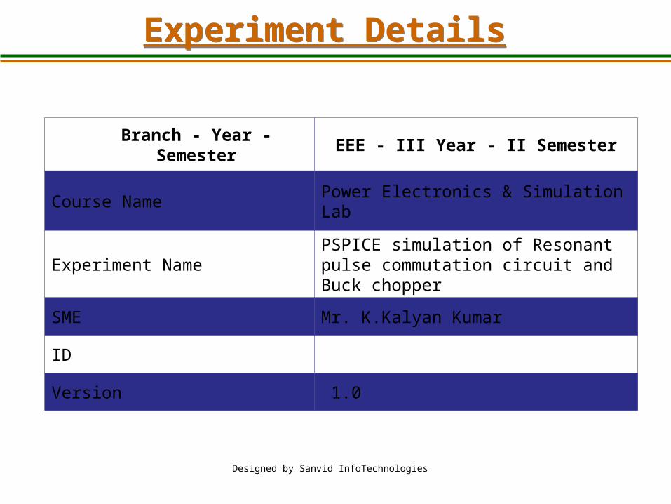
Branch - Year - Semester EEE - III Year - II Semester
Course Name Power Electronics & Simulation Lab
Experiment Name PSPICE simulation of Resonant pulse commutation circuit and Buck chopper
SME Mr. K.Kalyan Kumar
ID
Version 1.0
Experiment DetailsExperiment Details
Designed by Sanvid InfoTechnologies
Aim of the ExperimentAim of the Experiment
• To find the Performance of a Resonant Pulse Commutation Circuit and
Buck Chopper.
• To observe the Voltage and current waveforms at various points.
Apparatus RequiredApparatus Required
Designed by Sanvid InfoTechnologies
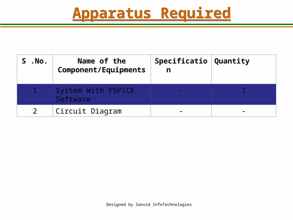
S .No. Name of the Component/Equipments
Specification Quantity
1 System With PSPICE Software - 1
2 Circuit Diagram - -
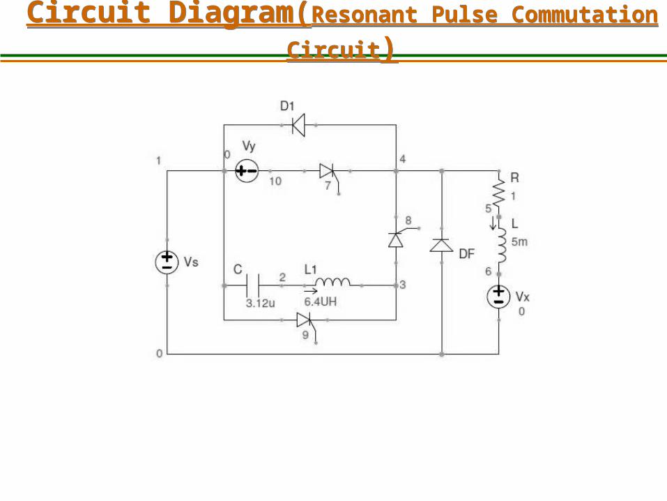
Circuit Diagram(Resonant Pulse
Commutation Circuit)Circuit Diagram(Resonant Pulse
Commutation Circuit)
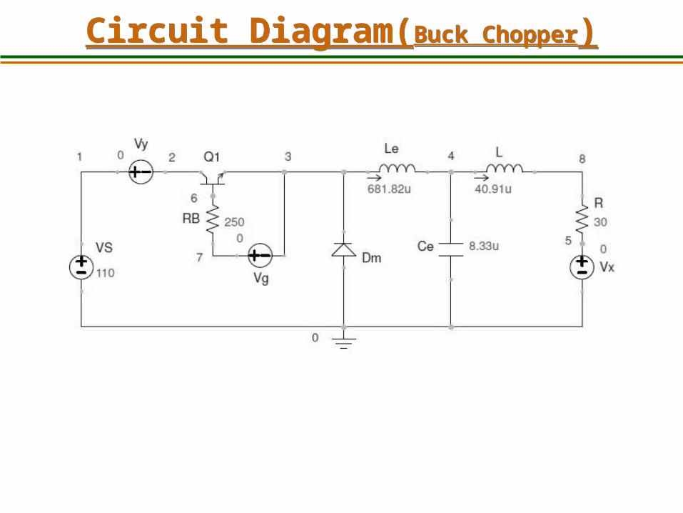
Circuit Diagram(Buck Chopper)Circuit Diagram(Buck Chopper)
Theory and ApplicationsTheory and Applications• Resonant pulse commutation circuit is used to commutate the conducting thyristors.
• Buck chopper will step downs the fixed DC voltage to variable DC voltage.
Principle of Operation• In resonant pulse commutation the Capacitor C charges up in the dot as positive before a gate pulse is applied to the Transistor. When transistor is triggered, the resulting current has two components.
• The constant load current I load flows through R - L load. This is ensured by the large reactance in series with the load and the freewheeling diode clamping it.
• A sinusoidal current flows through the resonant L-C circuit to charge-up C with the dot as negative at the end of the half cycle.
Theory and ApplicationsTheory and Applications A buck converter with the transistor and the diode making up the Bi-positional switch of the
power pole. Turning on the transistor increases the inductor current. When the transistor is turned off, the inductor current freewheels through the diode. The dc-dc converters can operate in two distinct modes with respect to the inductor current iL
Continuous Current Mode (Where Inductor current is always greater than zero)
Discontinuous Current Mode (Inductor current is zero during portion of switching period). The CCM is preferred for high efficiency and good utilization of semiconductor switches and
passive components. The DCM is used in applications where the inductor current is zero at beginning and at the end
of switching period. The output voltage is dependent on the duty cycle. The output voltage is
Vo=DVin Where D is duty cycle
Theory and ApplicationsTheory and Applications
Applications:
Resonant Pulse Commutation
• Commutation for the SCRs
Buck Chopper• Automotive applications• Power amplifier applications• Adaptive control applications• Battery power systems• Consumer Electronics• Communication Applications Battery Charging circuits• In heaters and welders• DC motor drives• Power factor correction circuits• Distributed power architecture systems
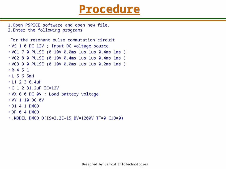
1.Open PSPICE software and open new file.2.Enter the following programs
For the resonant pulse commutation circuit• VS 1 0 DC 12V ; Input DC voltage source• VG1 7 0 PULSE (0 10V 0.0ms 1us 1us 0.4ms 1ms )• VG2 8 0 PULSE (0 10V 0.4ms 1us 1us 0.4ms 1ms )• VG3 9 0 PULSE (0 10V 0.0ms 1us 1us 0.2ms 1ms )• R 4 5 1• L 5 6 5mH• L1 2 3 6.4uH• C 1 2 31.2uF IC=12V• VX 6 0 DC 0V ; Load battery voltage• VY 1 10 DC 0V• D1 4 1 DMOD• DF 0 4 DMOD• .MODEL DMOD D(IS=2.2E-15 BV=1200V TT=0 CJO=0)
Designed by Sanvid InfoTechnologies
ProcedureProcedure
Designed by Sanvid InfoTechnologies
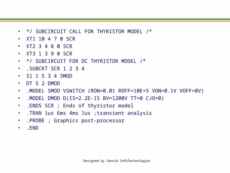
• */ SUBCIRCUIT CALL FOR THYRISTOR MODEL /*• XT1 10 4 7 0 SCR• XT2 3 4 8 0 SCR• XT3 1 3 9 0 SCR• */ SUBCIRCUIT FOR DC THYRISTOR MODEL /*• .SUBCKT SCR 1 2 3 4• S1 1 5 3 4 SMOD• DT 5 2 DMOD• .MODEL SMOD VSWITCH (RON=0.01 ROFF=10E+5 VON=0.1V VOFF=0V)• .MODEL DMOD D(IS=2.2E-15 BV=1200V TT=0 CJO=0)• .ENDS SCR ; Ends of thyristor model• .TRAN 1us 6ms 4ms 1us ;transient analysis• .PROBE ; Graphics post-processor• .END
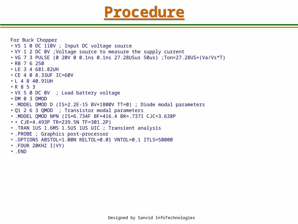
For Buck Chopper• VS 1 0 DC 110V ; Input DC voltage source• VY 1 2 DC 0V ;Voltage source to measure the supply current• VG 7 3 PULSE (0 20V 0 0.1ns 0.1ns 27.28USus 50us) ;Ton=27.28US=(Va/Vs*T)• RB 7 6 250• LE 3 4 681.82UH• CE 4 0 8.33UF IC=60V• L 4 8 40.91UH• R 8 5 3• VX 5 0 DC 0V ; Load battery voltage• DM 0 3 DMOD • .MODEL DMOD D (IS=2.2E-15 BV=1800V TT=0) ; Diode modal parameters• Q1 2 6 3 QMOD ; Transistor modal parameters• .MODEL QMOD NPN (IS=6.734F BF=416.4 BR=.7371 CJC=3.638P • + CJE=4.493P TR=239.5N TF=301.2P)• .TRAN 1US 1.6MS 1.5US 1US UIC ; Transient analysis• .PROBE ; Graphics post-processor• .OPTIONS ABSTOL=1.00N RELTOL=0.01 VNTOL=0.1 ITL5=50000• .FOUR 20KHZ I(VY)• .END
Designed by Sanvid InfoTechnologies
ProcedureProcedure

• Enter the Program With out errors.
• Waveforms should be noted without parallax error.
• Don't forget to save the Program at the end of every line.
Designed by Sanvid InfoTechnologies
PrecautionsPrecautions
Designed by Sanvid InfoTechnologies
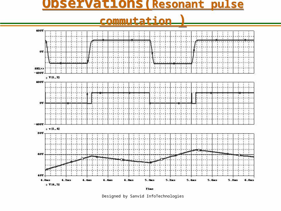
Observations(Resonant pulse
commutation )Observations(Resonant pulse
commutation )
Designed by Sanvid InfoTechnologies
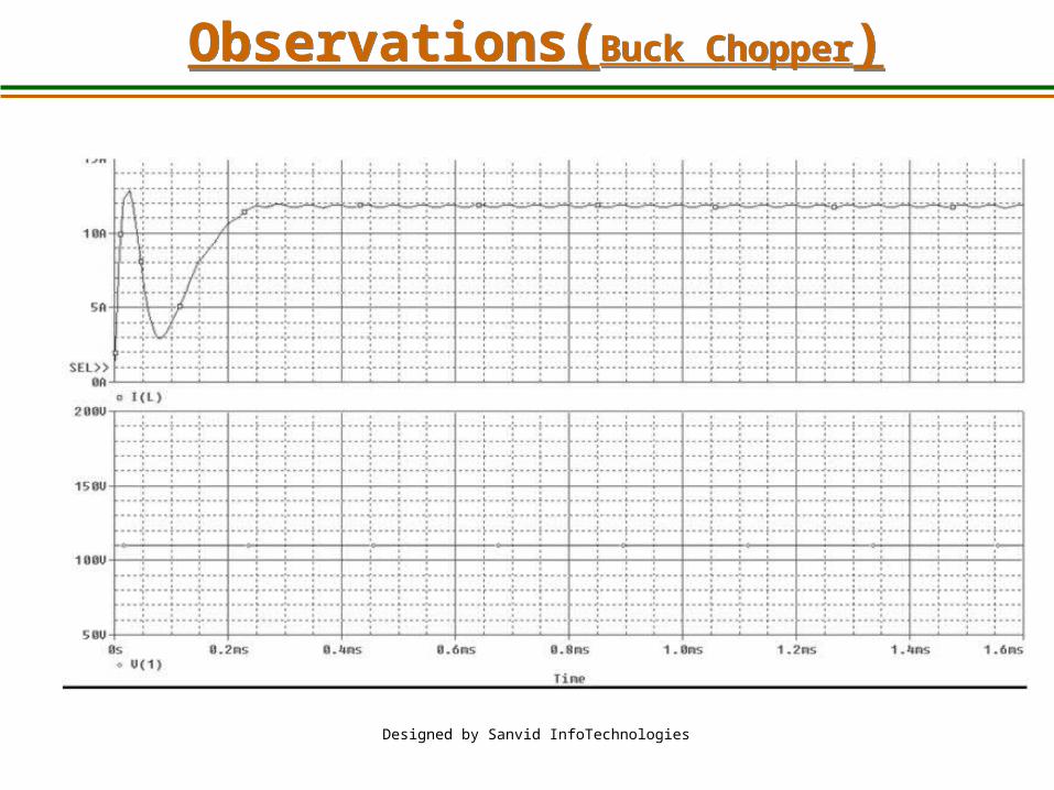
Observations(Buck Chopper)Observations(Buck Chopper)
• Various voltages across the capacitor, inductor and load has been
observed in resonant pulse commutation circuit and buck chopper
Designed by Sanvid InfoTechnologies
InferenceInference
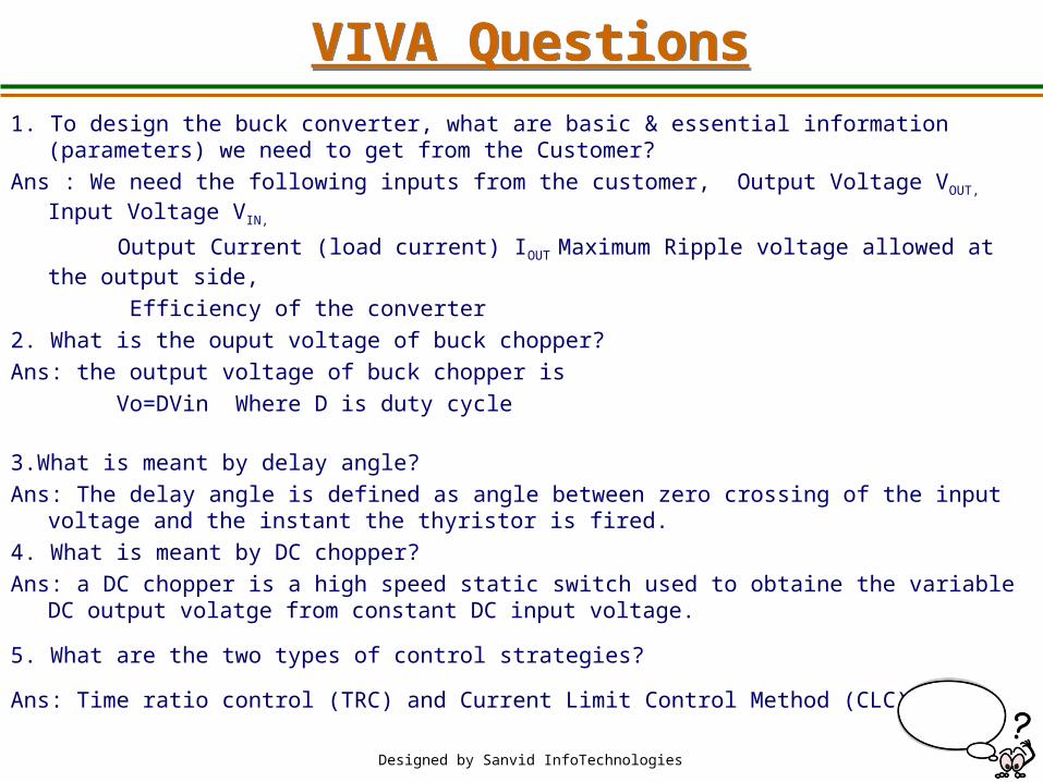
1. To design the buck converter, what are basic & essential information (parameters) we need to get from the Customer?
Ans : We need the following inputs from the customer, Output Voltage VOUT, Input Voltage VIN,
Output Current (load current) IOUT Maximum Ripple voltage allowed at the output side,
Efficiency of the converter
2. What is the ouput voltage of buck chopper?
Ans: the output voltage of buck chopper is
Vo=DVin Where D is duty cycle
3.What is meant by delay angle?
Ans: The delay angle is defined as angle between zero crossing of the input voltage and the instant the thyristor is fired.
4. What is meant by DC chopper?
Ans: a DC chopper is a high speed static switch used to obtaine the variable DC output volatge from constant DC input voltage.
5. What are the two types of control strategies?
Ans: Time ratio control (TRC) and Current Limit Control Method (CLC)
Designed by Sanvid InfoTechnologies
VIVA QuestionsVIVA Questions
Designed by Sanvid InfoTechnologies
6. What is meant by commutation?
Ans: It is the process of changing the direction of current flow in a particular path of the circuit. This process is used in thyristors for turning it off.