Embed Size (px)
Citation preview
EX/P4-23
1
Results from the CDX-U Lithium Wall and NSTX Lithium Pellet Injection
and Evaporation Experiments
R. Majeski 1), H. Kugel 1), M.G. Bell 1), R. E. Bell 1), P. Beiersdorfer 5), C. Bush 2),
R. Doerner 3), D. Gates 1), T. Gray 1), R. Kaita 1), B. Leblanc 1), R. Maingi 2),
D. Mansfield 1), J. Menard 1), D. Mueller 1), S. Paul 1), R. Raman 4), A.L. Roquemore 1),
C.H. Skinner 1), S. Sabbagh 5), V. Soukhanovskii 6), J. Spaleta 1), T. Stevenson 1),
J. Timberlake 1), L. Zakharov 1)
1) Princeton Plasma Physics Laboratory, Princeton, NJ, USA
2) Oak Ridge National Laboratory, Oak Ridge, TN, USA
3) University of California at San Diego, La Jolla, CA, USA
4) University of Washington, Seattle, WA, USA
5) Columbia University, New York, NY, USA
6) Lawrence Livermore National Laboratory, Livermore, CA, USA
e-mail contact of main author: [email protected]
Abstract. CDX-U has been operated with the vacuum vessel wall and limiter surfaces nearly completely coated with lithium, producing dramatic improvements to plasma performance. Discharges achieved global energy confinement times up to 6 ms, exceeding previous CDX-U results by a factor of 5, and ITER98P(y,1) scaling by 2 - 3. Lithium wall coatings up to 1000 Å thick were applied between discharges by electron-beam-induced evaporation of a lithium-filled limiter and vapor deposition from a resistively heated oven. The e-beam power was modest (1.6 kW) but it produced up to 60 MW/m2 power density in a 0.3 cm2 spot; the duration was up to 300 s. Convective transport of heat away from the beam spot was so effective that the entire lithium inventory (140 g) was heated to evaporation (400-500 °C) and there was no observable hot spot on the lithium surface within the beam footprint. These results are promising for use of lithium plasma-facing components in reactor scale devices. Lithium coating has also been applied to NSTX carbon plasma-facing surfaces, to control the density rise during long-duration H-modes for non-inductive current sustainment. First, lithium pellets were injected into sequences of Ohmically heated helium plasmas in both center stack limiter (CSL) and lower single-null divertor (LSND) configurations to deposit a total of 25 - 30 mg of lithium on the respective plasma contact areas. In both cases, the first subsequent L mode, deuterium discharge with NBI showed a reduction in the volume-average density by a factor ~3 compared to similar discharges before the lithium coating. Recently, a lithium evaporator was installed aimed toward the graphite tiles of the lower center stack and divertor. Twelve depositions, ranging from about 10 mg to 5 g of lithium, were performed. The effects on LSND L-mode, double-null divertor (DND) H-mode, and DND reversed-shear plasmas were variable but, immediately after coating, there were decreases in the density and significant increases in electron and ion temperature, neutron rate, confinement time, and edge flow velocity, and reductions in H-mode ELM frequency. For several days of operation after lithium coating, the ratio of oxygen to carbon emission was lower than with boronization.
1. Introduction
Plasma performance is observed to improve as the global wall recycling coefficient R is
reduced. [1,2] Techniques such as divertor pumping and lithium wall coatings have
succeeded in reducing R by 5 – 15%. In the Tokamak Fusion Test Reactor (TFTR), [3] a
factor of two increase in the confinement time was produced with extensive lithium coatings
of the carbon wall, and a 15% reduction in recycling. [4] In the DIII-D device, divertor
cryopumping resulted in a strong increase in the edge pedestal temperature with only a
modest decrease in global recycling. [5] Experiments on T11-M utilized a compact liquid
lithium rail limiter, in combination with partial solid lithium coatings on the stainless steel
vessel wall. [2] Significant changes in tokamak discharge characteristics are predicted for
discharges with global recycling coefficients less than 50%. [6,7] Here we report the results of experiments with liquid lithium plasma limiting surfaces and aggressive lithium coatings on metallic walls to further reduce recycling in CDX-U. [8] The use of lithium coatings on
EX/P4-23
2
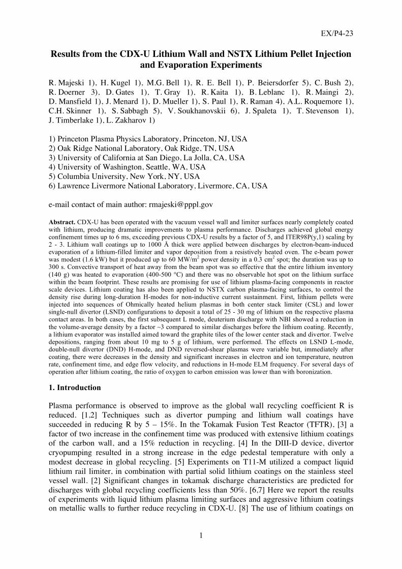
the plasma facing components (PFCs) has also been investigated on NSTX, as a tool for density and recycling control, using both lithium pellet injection and evaporated lithium. Since, like TFTR, NSTX has a carbon wall, these experiments also provide a bridge to previous work. 2. Lithium wall experiments in CDX-U Two new techniques were used to produce wall coatings of lithium – a resistive evaporator and an electron beam (e-beam) evaporation system. The resistive evaporator is a collimated oven mounted in a port at the outboard midplane, which continuously deposits lithium on the walls and center stack limiter of CDX-U, producing coatings up to 100 Å thick between discharges (5 - 7 minute interval). The e-beam is focused on a 600 cm2 pool of lithium in a shallow toroidal reservoir at the bottom of the vessel which also acts as a limiter for the discharges. The e-beam system was capable of much higher deposition rates - over 1000 Å in the 1 min interval immediately preceding a discharge. Both systems operated simultaneously, producing near 100% coverage of the vessel wall and centerstack. A cross section of CDX-U showing the lithium systems is shown in Figure 1. Particle pumping rates up to 3 ! 1021 D/s were obtained, exceeding the wall pumping rate achieved in a lithium-aided TFTR supershot. [4] However, the active wall area in CDX-U is two orders of magnitude smaller than in TFTR. Global recycling coefficients for discharges with a full (2000 cm2) liquid lithium limiter were estimated at 30%.
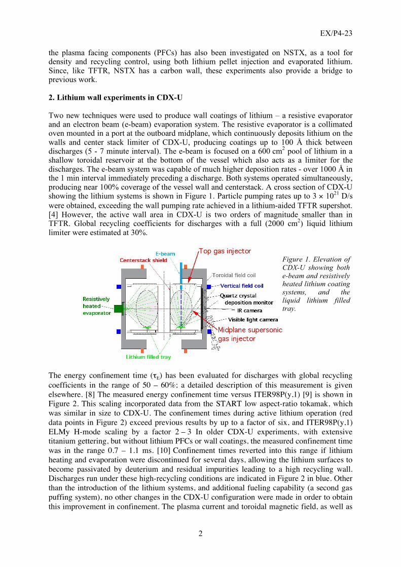
The energy confinement time ("E) has been evaluated for discharges with global recycling
coefficients in the range of 50 – 60%; a detailed description of this measurement is given
elsewhere. [8] The measured energy confinement time versus ITER98P(y,1) [9] is shown in
Figure 2. This scaling incorporated data from the START low aspect-ratio tokamak, which
was similar in size to CDX-U. The confinement times during active lithium operation (red
data points in Figure 2) exceed previous results by up to a factor of six, and ITER98P(y,1)
ELMy H-mode scaling by a factor 2 – 3 In older CDX-U experiments, with extensive
titanium gettering, but without lithium PFCs or wall coatings, the measured confinement time
was in the range 0.7 – 1.1 ms. [10] Confinement times reverted into this range if lithium
heating and evaporation were discontinued for several days, allowing the lithium surfaces to
become passivated by deuterium and residual impurities leading to a high recycling wall.
Discharges run under these high-recycling conditions are indicated in Figure 2 in blue. Other
than the introduction of the lithium systems, and additional fueling capability (a second gas
puffing system), no other changes in the CDX-U configuration were made in order to obtain
this improvement in confinement. The plasma current and toroidal magnetic field, as well as
Figure 1. Elevation of CDX-U showing both e-beam and resistively heated lithium coating systems, and the liquid lithium filled tray.
EX/P4-23
3
the size of the plasma (determined by the limiter positions) were identical for the pre- and
post-lithium discharges. The operating gas (deuterium) was the same in all cases although in
many cases the lithium discharges ran at somewhat lower density. The largest contributor to
the confinement time increase for discharges with active lithium evaporation was a reduction
in loop voltage, and therefore input power, by up to a factor of 4. Stored energy also
increased in discharges with active lithium evaporation, and the stored energy peaked later in
the discharge than was the case without evaporation.
The carbon impurity ion temperature increased from the 20-30 eV range, without lithium
coatings, to 60-70 eV, for lithium-limited discharges, as determined by Doppler broadening
of the 466 nm C IV emission line. The edge electron temperature increased from ~20 eV to
~30 eV with lithium, as determined by a triple Langmuir probe. The levels of carbon and
oxygen emission were reduced by about a factor of 10 in the lithium discharges. The loop
voltage required to maintain a 70 kA plasma current was reduced from 2-3 V in pre-lithium
discharges to 0.5 V or less in lithium discharges. Increased confinement time is most strongly
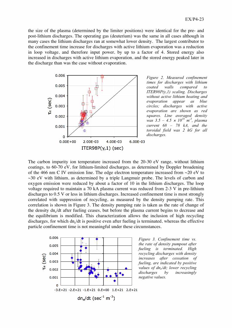
correlated with suppression of recycling, as measured by the density pumping rate. This
correlation is shown in Figure 3. The density pumping rate is taken as the rate of change of
the density dne/dt after fueling ceases, but before the plasma current begins to decrease and
the equilibrium is modified. This characterization allows the inclusion of high recycling
discharges, for which dne/dt is positive even after fueling is terminated, whereas the effective
particle confinement time is not meaningful under these circumstances.
Figure 2. Measured confinement times for discharges with lithium coated walls compared to ITER98P(y,1) scaling. Discharges without active lithium heating and evaporation appear as blue circles; discharges with active evaporation are shown as red squares. Line averaged density was 3.5 – 4.5 ! 10
18 m
-3, plasma
current 68 – 78 kA, and the toroidal field was 2 kG for all discharges.
Figure 3. Confinement time vs. the rate of density pumpout after fueling is terminated. High recycling discharges with density increases after cessation of fueling, are indicated by positive values of dne/dt; lower recycling discharges by increasingly negative values.
EX/P4-23
4
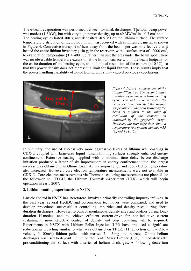
The e-beam evaporation was performed between tokamak discharges. The total beam power was modest (1.6 kW), but with very high power density, up to 60 MW/m2 in a 0.3 cm2 spot. The heating cycles lasted 300 s, and deposited ~0.5 MJ on the lithium surface. The surface temperature distribution of the liquid lithium was recorded with an infrared camera, as shown in Figure 4. Convective transport of heat away from the beam spot was so effective that it heated the entire lithium inventory (140 g) in the reservoir, with a surface area of ~2000 cm2, to evaporation temperature (T > 400 °C) rather than just the area under the beam spot. There was no observable temperature excursion at the lithium surface within the beam footprint for the entire duration of the heating cycle, to the limit of resolution of the camera (<10 °C), so that this power density does not represent a limit for liquid lithium. These results imply that the power handling capability of liquid lithium PFCs may exceed previous expectations.
In summary, the use of successively more aggressive levels of lithium wall coatings in CDX-U coupled with large-area liquid lithium limiting surfaces strongly enhanced energy confinement. Extensive coatings applied with a minimal time delay before discharge initiation produced a factor of six improvement in energy confinement time, the largest increase ever obtained in an Ohmic tokamak. The impurity ion and edge electron temperature also increased. However, core electron temperature measurements were not available in CDX-U. Core electron measurements via Thomson scattering measurements are planned for the follow-on to CDX-U, the Lithium Tokamak eXperiment (LTX), which will begin operation in early 2007.
2. Lithium coating experiments in NSTX
Particle control in NSTX has, heretofore, involved primarily controlling impurity influxes. In
the past year, several HeGDC and boronization techniques were compared, and used to
develop procedures successful at controlling impurities and density rises during short-
duration discharges. However, to control spontaneous density rises and profiles during long-
duration H-modes, and to achieve efficient current-drive for non-inductive current
sustainment, more effective control of density and edge recycling will be required.
Experiments in NSTX with Lithium Pellet Injection (LPI) have produced a significant
reduction in recycling similar to what was obtained on TFTR. [11] Injection of 1 – 2 low
velocity (~100m/s) lithium pellets with masses 2 – 5 mg into repeated Ohmic helium
discharges was used to deposit lithium on the Center Stack Limiter (CSL) immediately after
pre-conditioning this surface with a series of helium discharges. A following deuterium
Figure 4. Infrared camera view of the lithium-filled tray 200 seconds after initiation of an electron beam heating cycle. The red circle indicates the beam location; note that the surface temperature in the area heated by the beam is uniform to the limit of resolution of the camera, as indicated by the grayscale image. However, the tray edge does show a temperature rise (yellow denotes +55 °C, red +110°C.
Tray width: 10 cm.

EX/P4-23
5
discharge limited on the CSL with NBI, then exhibited a reduction in the volume-average
density by a factor of about three compared to a similar discharge prior to the coating
sequence, and a peaked density profile. The density reverted to the pre-LPI level after two
further plasma discharges as the lithium was passivated by exposure to the plasma. In a
subsequent experiment, Lower Single Null Divertor (LSND) helium discharges were used to
degas the lower divertor target. This was followed by LPI into a sequence of similar LSND
helium discharges to deposit lithium on the divertor target, as indicated by TV images of
neutral lithium line emission during the discharges. In the first LSND deuterium plasma with
NBI after the lithium coating, the volume-average density exhibited a factor of about three
reduction from a similar discharge before the coating, and the density profile was again
Figure 5. A reduction in the volume-average density by a factor of about three was exhibited by Lower Single Null divertor NBI discharges following deposition of 25 mg of lithium using repeated Lithium Pellet Injection (LPI) into Ohmic helium discharges.
peaked. This is illustrated in Figure 5, which also shows that the rate of density rise in the post lithium shot is below the NB fueling rate. These results demonstrated that the required
edge pumping in diverted plasmas could be obtained by lithium coating, motivating the
development of a lithium evaporator for performing routine lithium coating over a significant
fraction of the plasma facing surfaces.
A lithium evaporator (referred to as LITER-1) was installed on an upper port of the NSTX
vacuum vessel with its output nozzle aimed downward toward the graphite tiles of the lower
divertor and center stack. The evaporator reservoir contained about 30 g of lithium initially
and was heated electrically to temperatures in the range 450 – 680°C. This produced total
evaporation rates of 0.08 to 35 mg/min with a Gaussian-like angular distribution with a full
width of about 22° at 1/e of peak intensity. Twelve separate significant lithium depositions
ranging from 1.6 mg to 4.8 g were performed for a total deposition of 9 g. If averaged over
the entire 40 m2 area of the PFCs, this total would correspond to an average lithium thickness
of 420 nm (about 1500 monolayers of elemental lithium). Table I summarizes the
evaporation amount, evaporation duration, the time to the next discharge, the PFC
conditioning applied prior to evaporation, the discharge type, and other experimental
information. In the initial experiments, 4 evaporations were performed (E-2, -3, -4, -6). Only
HeGDC (10 – 30 min) was used to condition the graphite PFCs prior to each evaporation.
These evaporations were evaluated using NBI heated, L-mode LSND, deuterium discharges
(Ip = 1 MA, PNBI = 4 – 5 MW). No effects on the volume-average density evolution or plasma

EX/P4-23
6
performance were observed. This is in noteworthy contrast to the LPI results discussed
above, which exhibited a relatively strong effect on the density (Fig. 5) with only about
25 mg of lithium coating.
TABLE I. SUMMARY OF THE EXPERIMENTAL SEQUENCE. Evaporation
Number Total Lithium
(mg) Evaporation
Duration (min)
Time to Discharge
(min)
PFC Conditioning
Method
Discharge Type
Comments
E-1, 1.6 11 HeGDC testing E-2, 14.3 245 151 HeGDC L No change E-3 77.0 128 11 HeGDC L No change E-4 215 128 167 HeGDC L No change E-5 0 testing E-6 643 369 85 HeGDC L No change E-7 378 63 23 6 He Discharges L First L-mode changes E-8 0 testing E-9 440 76 75 HeGDC H First H-mode changes
E-10 203 50 17 HeGDC H No change E-11 295 36 25 HeGDC H Marginal change E-12 4780 12.3 160 HeGDC H Similar to E-9 E-13 1046 66 24 HeGDC H Similar to E-9 E-14 1008 28 8 HeGDC H Similar to E-9
To test the effects of degassing the graphite PFCs prior to the lithium deposition, evaporation
E-7 was performed after running 6 Ohmically heated, helium discharges of the same shape.
The evaporation time and the time to the subsequent discharge were also decreased to
minimize possible passivation of the lithium by exposure to the residual gas in the vacuum
chamber (total pressure (2 – 4) ! 10-6 Pa, dominated by water fractions). After this
evaporation, the first noteworthy changes plasma behavior were observed in the subsequent
NBI heated, L-mode, LSND, deuterium discharge (Ip = 1 MA, PNBI = 6 MW). Shown in
Figure 6 are the changes in volume-averaged ne and Te and their radial profiles, before and
after the lithium deposition. The volume-averaged density exhibited almost a 30% decrease
and the electron temperature Te increased by ~15%. In addition, the ion temperature
increased ~20% and the DD fusion neutron emission increased ~20%. However, for the
following discharge, the density waveform reverted to that of the pre-lithium discharge,
although the improvements in the temperature and neutron rate persisted for several more
discharges. In order to separate possible pumping effects of the degassed graphite tiles from
0.0
0.5
1.0
Volu
me-a
vera
ge T
e (
keV
)
0.0 0.1 0.2 0.3 0.40.0
0.1
0.2
Time (s)
0
1
2
Te (
keV
)
0.38s
0.5 1.0 1.5Radius (m)
Volu
me-a
vera
ge n
e (
10
20m
-3)
ne (
10
20m
-3)
120475
120464
120474
before Li
after Li}0.0
0.1
0.2
0.3
0.4
0.5 0.38s
Figure 6. A LSND L-mode deuterium discharge (Ip = 1 MA, PNBI = 6 MW) exhibited a ~30% decrease in ne and ~15% increase in Te after 380 mg lithium evaporation following He discharge conditioning.
EX/P4-23
7
those of the lithium coating, the graphite was again degassed with 6 Ohmically heated,
helium discharges of the same shape but no lithium was deposited. Under these conditions,
the reference discharge exhibited about a 14% decrease in density, only about half of the
density reduction observed after evaporation E-7.
The L-mode experiment was followed by evaporation E-9 to test H-mode plasmas by
depositing a comparable amount of lithium, preceded by only HeGDC conditioning. The first
reference NBI heated, H-mode, DND (with lower x-point favored downward), deuterium
discharge after this evaporation exhibited a minimal change in the average density (10-15%)
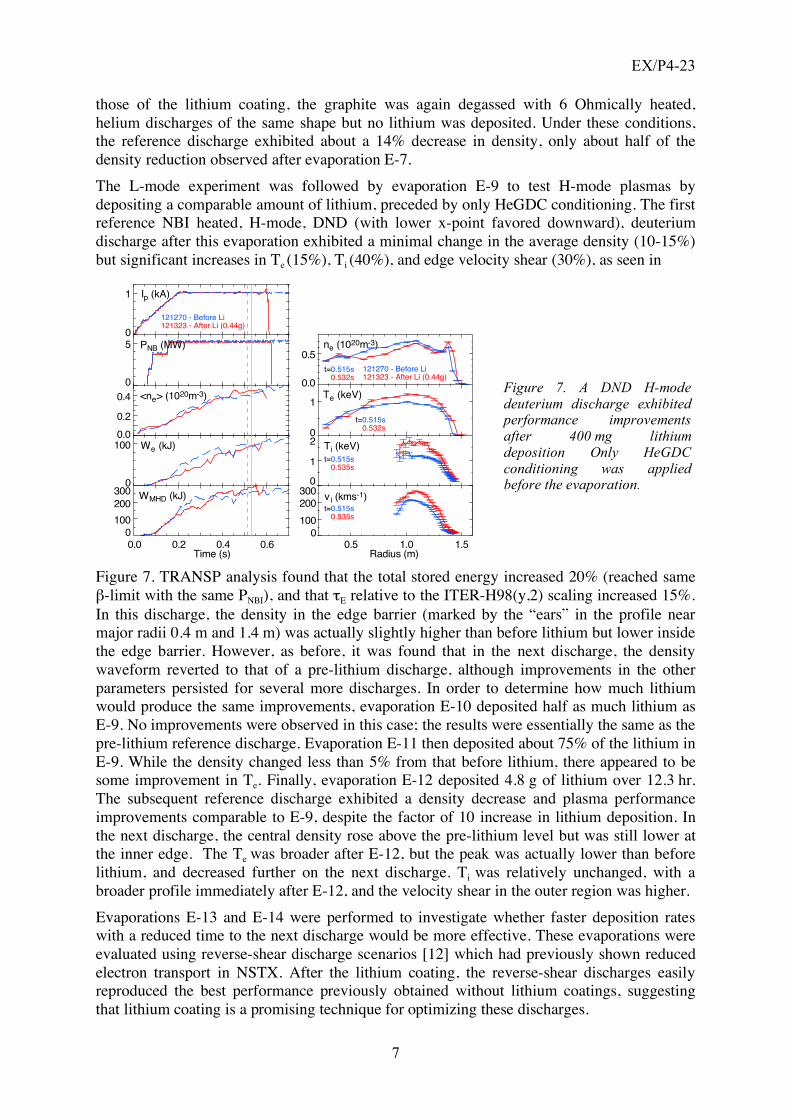
but significant increases in Te (15%), Ti (40%), and edge velocity shear (30%), as seen in
Figure 7. TRANSP analysis found that the total stored energy increased 20% (reached same
#-limit with the same PNBI), and that "E relative to the ITER-H98(y,2) scaling increased 15%.
In this discharge, the density in the edge barrier (marked by the “ears” in the profile near
major radii 0.4 m and 1.4 m) was actually slightly higher than before lithium but lower inside
the edge barrier. However, as before, it was found that in the next discharge, the density
waveform reverted to that of a pre-lithium discharge, although improvements in the other
parameters persisted for several more discharges. In order to determine how much lithium
would produce the same improvements, evaporation E-10 deposited half as much lithium as
E-9. No improvements were observed in this case; the results were essentially the same as the
pre-lithium reference discharge. Evaporation E-11 then deposited about 75% of the lithium in
E-9. While the density changed less than 5% from that before lithium, there appeared to be
some improvement in Te. Finally, evaporation E-12 deposited 4.8 g of lithium over 12.3 hr.
The subsequent reference discharge exhibited a density decrease and plasma performance
improvements comparable to E-9, despite the factor of 10 increase in lithium deposition. In
the next discharge, the central density rose above the pre-lithium level but was still lower at
the inner edge. The Te was broader after E-12, but the peak was actually lower than before
lithium, and decreased further on the next discharge. Ti was relatively unchanged, with a
broader profile immediately after E-12, and the velocity shear in the outer region was higher.
Evaporations E-13 and E-14 were performed to investigate whether faster deposition rates
with a reduced time to the next discharge would be more effective. These evaporations were
evaluated using reverse-shear discharge scenarios [12] which had previously shown reduced
electron transport in NSTX. After the lithium coating, the reverse-shear discharges easily
reproduced the best performance previously obtained without lithium coatings, suggesting
that lithium coating is a promising technique for optimizing these discharges.
121270 - Before Li121323 - After Li (0.44g)
0
1 Ip (kA)
0
5 PNB (MW)
0
100
200
300 WMHD (kJ)
0.0 0.2 0.4 0.6
0.0
0.2
0.4 <ne> (1020m-3)
0
100 We (kJ)
Time (s)0.5 1.0 1.5
0
Radius (m)
0.0
0.5ne (1020m-3)
0
1Te (keV)
1
2 Ti (keV)
t=0.515s0.532s
121270 - Before Li121323 - After Li (0.44g)
0
100
200
300vi (kms-1)
t=0.515s0.532s
t=0.515s0.535s
t=0.515s0.535s
Figure 7. A DND H-mode deuterium discharge exhibited performance improvements after 400 mg lithium deposition Only HeGDC conditioning was applied before the evaporation.
EX/P4-23
8
The results indicate that for the present evaporator configuration and capability, performance
improvements appear not dependent on quantity of lithium deposited beyond a threshold of
about 400 mg. In addition, there are indications of possible long-term improvements in wall
conditions as a result of the lithium coating. In particular, the relative oxygen impurity
content, as indicated by the ratio of reference emission lines of oxygen and carbon, showed a
significant drop, by a factor ~2 – 10, which persisted for many days of operation after the
lithium evaporation.
The apparent difference in the effectiveness for density control of the lithium deposited by
pellet injection (~30 mg) and by evaporation (up to ~5 g) remains puzzling. It suggests that it
is only the lithium coating in the immediate vicinity of plasma contact with PFCs that is
effective, and that more narrowly targeted deposition by evaporation would be more effective
in this regard. The disappearance of the density pump-out after only one discharge, despite
enough lithium to absorb several times the entire fueling of the discharge, suggests that only
very thin surface layers of lithium are involved. In the case of the H-mode discharges, in
particular, experiments are planned to determine whether, even when the recycling is reduced
by lithium walls, improvements in particle confinement are occurring. This could cause the
observed secular rise in density as a result of NBI fueling and residual recycling from
uncoated regions of the PFCs.
This work supported by USDoE contract No. DE-AC02-76CH03073.
References
[1] STRACHAN, J. D., “Studies of global energy confinement in TFTR”, Nucl. Fusion 34 (1994) 1017. [2] MIRNOV, S. V., et al., “Li – CPS limiter in tokamak T-11M”, Fus. Eng. Des. 65 (2003) 455. [3] MANSFIELD, D. K., et al., “Enhancement of Tokamak Fusion Test Reactor performance by lithium conditioning”, Nucl. Fusion 41 (2001) 1823. [4] BUDNY, R., et al., “Particle balance in a TFTR supershot”, J. Nucl. Mater., 196-198 (1992) 462. [5] WEST, W. P., et al., “Energy, paticle, and impurity transport in quiescent double barrier discharges in DIII-D”, Phys. Plasmas 9 (2002) 1970. [6] KRASHENINNIKOV, S. I., et al., “On lithium walls and the performance of magnetic fusion devices”, Phys. Plasmas 10 (2003) 1678. [7] ZAKHAROV, L. E., et al., “Ignited spherical tokamaks and plasma regimes with Li walls”, Fus. Eng. Des. 72, (2004) 149. [8] MAJESKI, R., et al., “Enhanced Energy Confinement and Performance in a Low Recycling Tokamak, Phys. Rev. Lett. 97 (2006) 075002. [9]KARDAUN, O.J.W.F., et al., “Next Step Tokamak Physics: Confinement-oriented Global Database Analysis”, in Proc. 18th IAEA Fusion Energy Conf., Sorrento, 2000 (IAEA,Vienna, 2001), CD-ROM file ITERP/04, unpublished. [10] MUNSAT, T., et al., “Transient transport experiments in the current drive experiment upgrade spherical torus”, Phys. Plasmas 9 (2002) 480. [11] KUGEL, H. W., et al., "Effect of Lithium PFC Coatings on NSTX Density Control", in
Proc. of the 17th International Conference on Plasma Surface Interactions in Controlled
Fusion Devices, Hefei, China, May 22 – 26, 2006. [12] STUTMAN, D., et al., "Studies of improved electron confinement in low density L-mode National Spherical Torus Experiment discharges" in print in Phys. Plasmas 2006.