Embed Size (px)
Citation preview
Return loss and impedance
Piers Dawe
Mellanox
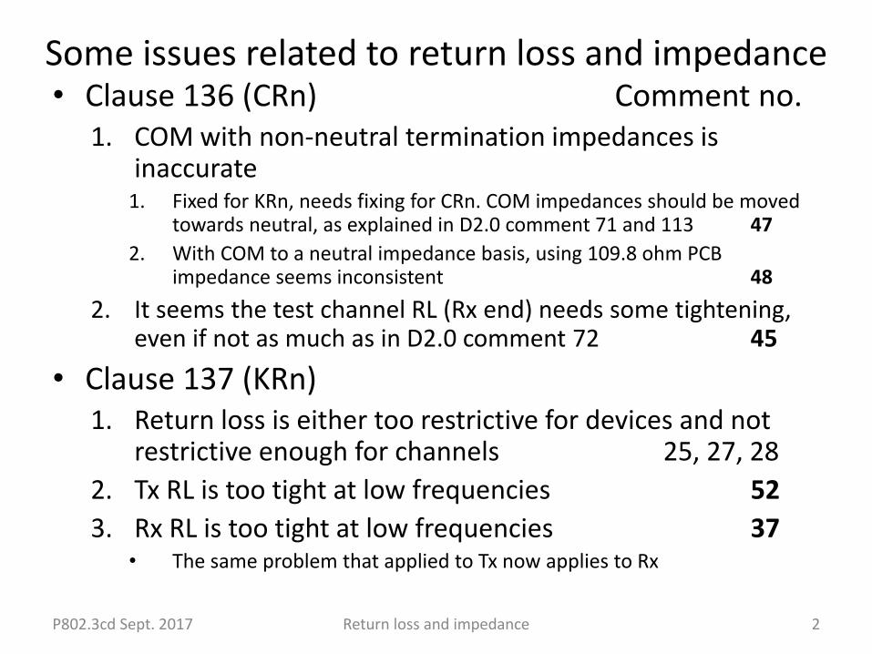
Some issues related to return loss and impedance • Clause 136 (CRn) Comment no.
1. COM with non-neutral termination impedances is inaccurate
1. Fixed for KRn, needs fixing for CRn. COM impedances should be moved towards neutral, as explained in D2.0 comment 71 and 113 47
2. With COM to a neutral impedance basis, using 109.8 ohm PCB impedance seems inconsistent 48
2. It seems the test channel RL (Rx end) needs some tightening, even if not as much as in D2.0 comment 72 45
• Clause 137 (KRn)1. Return loss is either too restrictive for devices and not
restrictive enough for channels 25, 27, 28
2. Tx RL is too tight at low frequencies 52
3. Rx RL is too tight at low frequencies 37• The same problem that applied to Tx now applies to Rx
P802.3cd Sept. 2017 Return loss and impedance 2
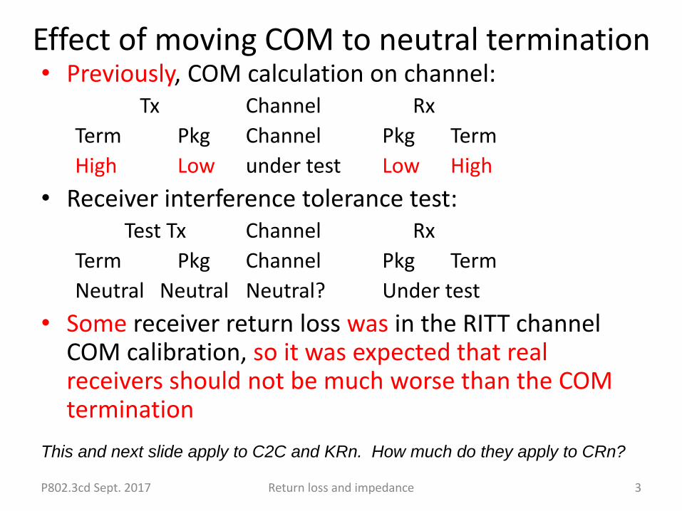
Effect of moving COM to neutral termination• Previously, COM calculation on channel:
Tx Channel Rx
Term Pkg Channel Pkg Term
High Low under test Low High
• Receiver interference tolerance test:Test Tx Channel Rx
Term Pkg Channel Pkg Term
Neutral Neutral Neutral? Under test
• Some receiver return loss was in the RITT channel COM calibration, so it was expected that real receivers should not be much worse than the COM termination
P802.3cd Sept. 2017 Return loss and impedance 3
This and next slide apply to C2C and KRn. How much do they apply to CRn?
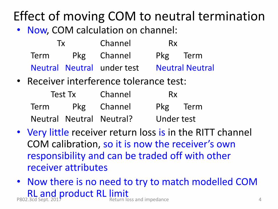
Effect of moving COM to neutral termination• Now, COM calculation on channel:
Tx Channel Rx
Term Pkg Channel Pkg Term
Neutral Neutral under test Neutral Neutral
• Receiver interference tolerance test:Test Tx Channel Rx
Term Pkg Channel Pkg Term
Neutral Neutral Neutral? Under test
• Very little receiver return loss is in the RITT channel COM calibration, so it is now the receiver’s own responsibility and can be traded off with other receiver attributes
• Now there is no need to try to match modelled COM RL and product RL limit
P802.3cd Sept. 2017 Return loss and impedance 4
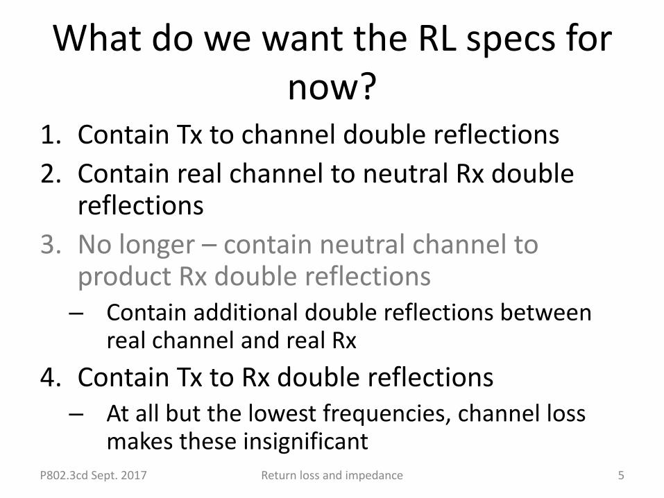
What do we want the RL specs for now?
1. Contain Tx to channel double reflections
2. Contain real channel to neutral Rx double reflections
3. No longer – contain neutral channel to product Rx double reflections– Contain additional double reflections between
real channel and real Rx
4. Contain Tx to Rx double reflections– At all but the lowest frequencies, channel loss
makes these insignificantP802.3cd Sept. 2017 Return loss and impedance 5
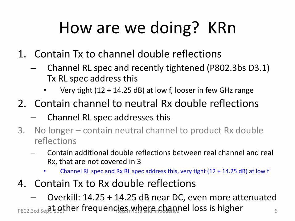
How are we doing? KRn
1. Contain Tx to channel double reflections– Channel RL spec and recently tightened (P802.3bs D3.1)
Tx RL spec address this• Very tight (12 + 14.25 dB) at low f, looser in few GHz range
2. Contain channel to neutral Rx double reflections– Channel RL spec addresses this
3. No longer – contain neutral channel to product Rx double reflections– Contain additional double reflections between real channel and real
Rx, that are not covered in 3• Channel RL spec and Rx RL spec address this, very tight (12 + 14.25 dB) at low f
4. Contain Tx to Rx double reflections– Overkill: 14.25 + 14.25 dB near DC, even more attenuated
at other frequencies where channel loss is higherP802.3cd Sept. 2017 Return loss and impedance 6
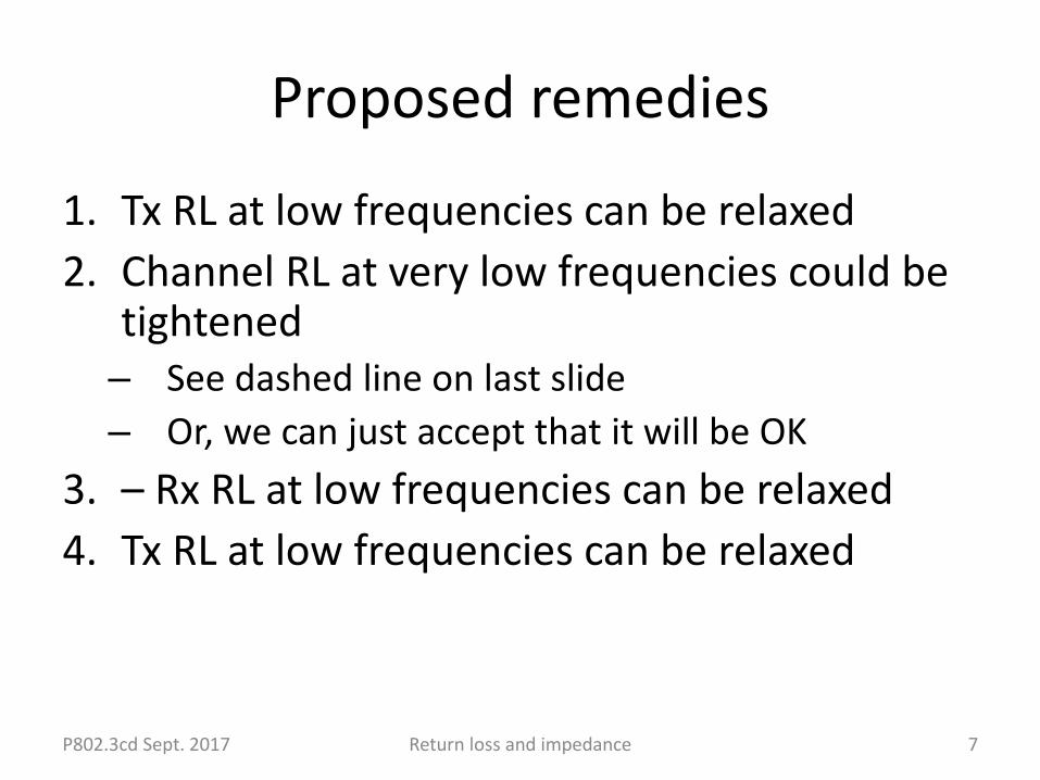
Proposed remedies
1. Tx RL at low frequencies can be relaxed
2. Channel RL at very low frequencies could be tightened– See dashed line on last slide
– Or, we can just accept that it will be OK
3. – Rx RL at low frequencies can be relaxed
4. Tx RL at low frequencies can be relaxed
P802.3cd Sept. 2017 Return loss and impedance 7
P802.3cd Sept. 2017 Return loss and impedance
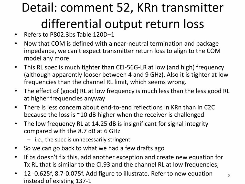
Detail: comment 52, KRn transmitter differential output return loss
• Refers to P802.3bs Table 120D–1
• Now that COM is defined with a near-neutral termination and package impedance, we can't expect transmitter return loss to align to the COM model any more
• This RL spec is much tighter than CEI-56G-LR at low (and high) frequency (although apparently looser between 4 and 9 GHz). Also it is tighter at low frequencies than the channel RL limit, which seems wrong.
• The effect of (good) RL at low frequency is much less than the less good RL at higher frequencies anyway
• There is less concern about end-to-end reflections in KRn than in C2C because the loss is ~10 dB higher when the receiver is challenged
• The low frequency RL at 14.25 dB is insignificant for signal integrity compared with the 8.7 dB at 6 GHz– i.e., the spec is unnecessarily stringent
• So we can go back to what we had a few drafts ago
• If bs doesn't fix this, add another exception and create new equation for Tx RL that is similar to the Cl.93 and the channel RL at low frequencies;
• 12 -0.625f, 8.7-0.075f. Add figure to illustrate. Refer to new equation instead of existing 137-1
8
For info: P802.3bs D3.3 comment 34 (C2C receiver differential input return loss)
• Changing the return loss spec for the receiver was a mistake, because the effects of receiver reflections to a nominal-impedance channel and transmitter are in the receiver interference tolerance test, and the extra reflections to a channel and transmitter with different impedances are controlled/accounted for by the channel COM, now based on nominal impedances, the new channel return loss spec and the transmitter return loss spec.
• From the simple formula for reflection at an impedance mismatch, one can see that these effects are close to additive, so controlling/accounting for them separately is OK. In other words, the receiver pays for its own reflections in the interference tolerance test, so we don't have to tell the receiver designer how to do his job in this regard.
• In Table 120D–5, revert 120D.3.1.1, Equation (120D-2) to 93.8.1.4, Equation (93-3).
P802.3cd Sept. 2017 Return loss and impedance 9
P802.3cd Sept. 2017 Return loss and impedance
Detail: comment 30, KRn receiver differential input return loss
• Now that COM is defined with a near-neutral termination and package impedance, receiver mismatch is the receiver designer's concern, not the standard's, unless it is very extreme, because the receiver interference tolerance test finds its effect combined with other receiver attributes
• We don't expect or need receiver RL to align to the COM model any more
• This RL is much tighter than CEI-56G-LR at low (and high) frequency (although apparently looser between 4 and 9 GHz)
• At low frequencies it is tighter than the channel RL limit, which seems wrong
• The effect of (good) RL at low frequency is much less than the less good RL at higher frequencies anyway
• There may be less concern about end-to-end reflections in KRn than in C2C because the loss is ~10 dB higher when the receiver is challenged
• So we can go back to what we had a few drafts ago
• Change "shall meet Equation (137-1)" to "shall meet Equation (93-3)" and delete Eq 137-1 and Fig 137-3. Or, change 14.25 - f to 12 -0.625f, revise the figure.
• If P802.3bs fixes this, we can refer to Table 120D–5 and remove 137.9.3.1 (comment 30)
10
0 5 10 15 20-15
-10
-5
0Return loss without TF RL
Frequency (GHz)
- R
etu
rn l
oss (
dB
)
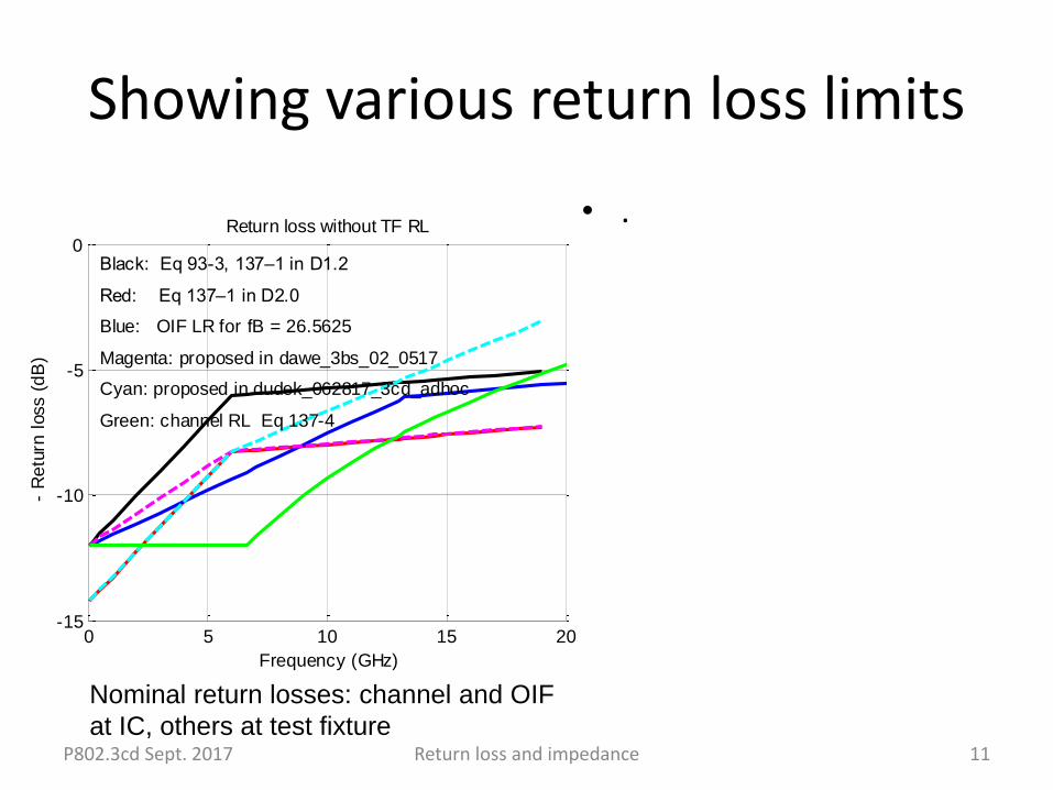
Black: Eq 93-3, 137–1 in D1.2
Red: Eq 137–1 in D2.0
Blue: OIF LR for fB = 26.5625
Magenta: proposed in dawe_3bs_02_0517
Cyan: proposed in dudek_062817_3cd_adhoc
Green: channel RL Eq 137-4
Showing various return loss limits
• .
P802.3cd Sept. 2017 Return loss and impedance 11
Nominal return losses: channel and OIF
at IC, others at test fixture
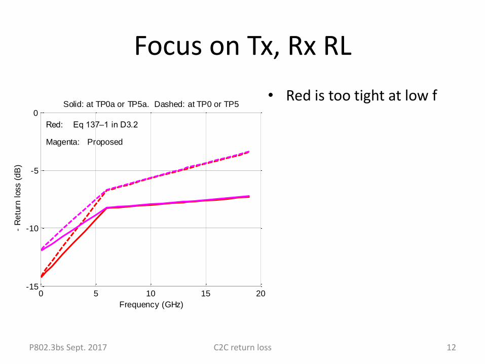
0 5 10 15 20-15
-10
-5
0
Frequency (GHz)
- R
etu
rn l
oss (
dB
)
Red: Eq 137–1 in D3.2
Magenta: Proposed
Solid: at TP0a or TP5a. Dashed: at TP0 or TP5
Focus on Tx, Rx RL
• Red is too tight at low f
P802.3bs Sept. 2017 C2C return loss 12
0 5 10 15 20-15
-10
-5
0Return loss
Frequency (GHz)
- R
etu
rn l
oss (
dB
)
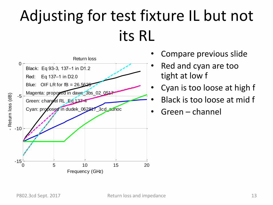
Black: Eq 93-3, 137–1 in D1.2
Red: Eq 137–1 in D2.0
Blue: OIF LR for fB = 26.5625
Magenta: proposed in dawe_3bs_02_0517
Cyan: proposed in dudek_062817_3cd_adhoc
Green: channel RL Eq 137-4
Adjusting for test fixture IL but not its RL
• Compare previous slide
• Red and cyan are too tight at low f
• Cyan is too loose at high f
• Black is too loose at mid f
• Green – channel
P802.3cd Sept. 2017 Return loss and impedance 13
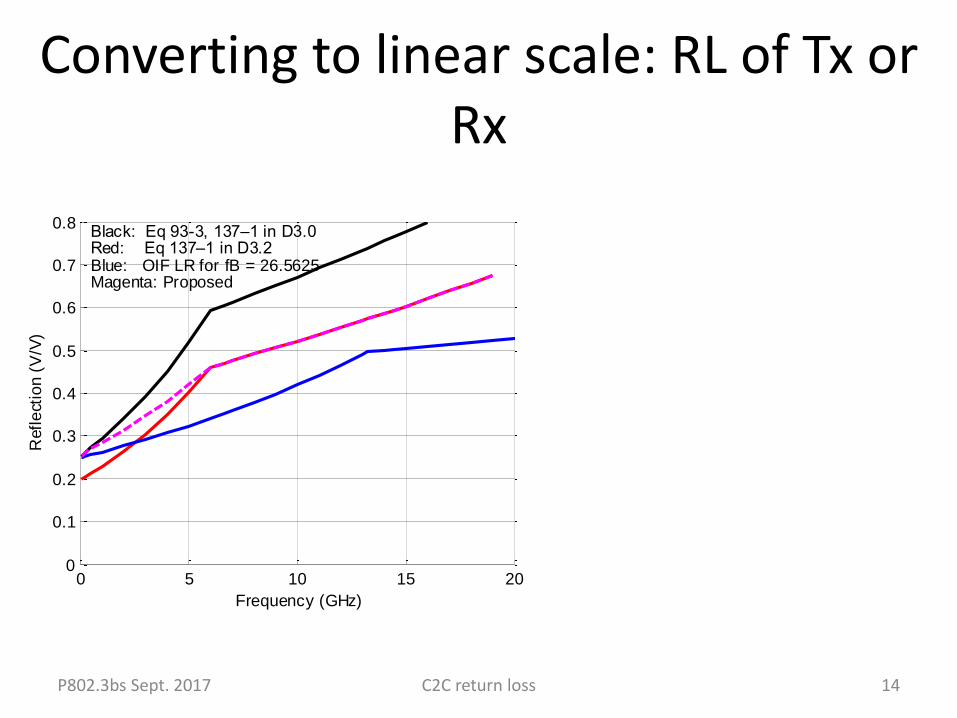
Converting to linear scale: RL of Tx or Rx
P802.3bs Sept. 2017 C2C return loss 14
0 5 10 15 200
0.1
0.2
0.3
0.4
0.5
0.6
0.7
0.8
Frequency (GHz)
Refl
ect
ion
(V
/V)
Black: Eq 93-3, 137–1 in D3.0Red: Eq 137–1 in D3.2Blue: OIF LR for fB = 26.5625Magenta: Proposed
0 5 10 15 200
0.05
0.1
0.15
0.2
0.25
0.3
0.35
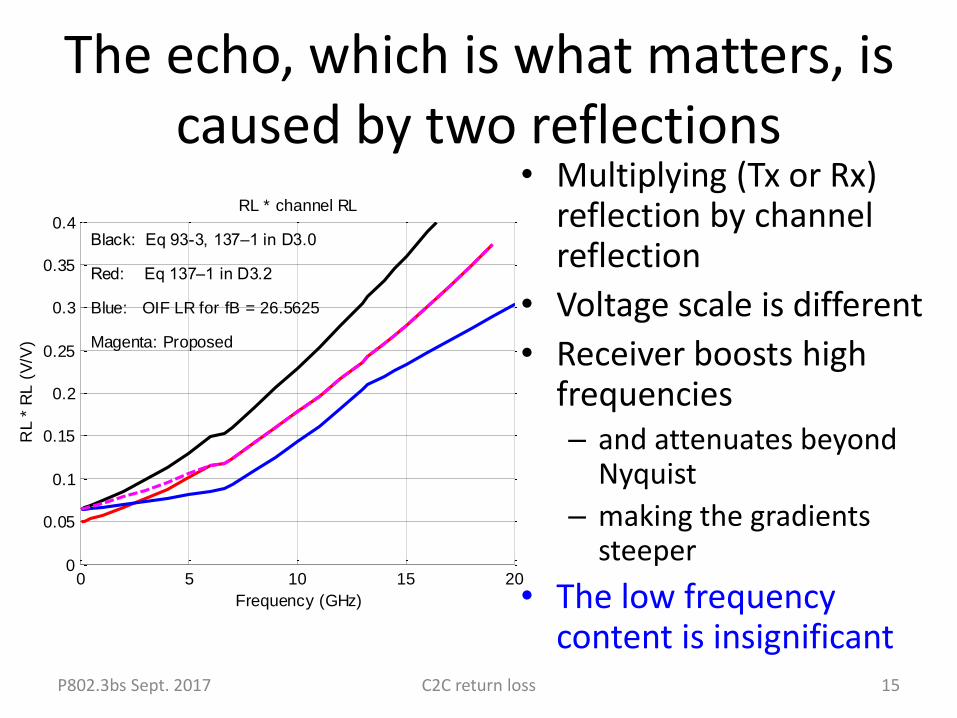
0.4RL * channel RL
Frequency (GHz)
RL *
RL
(V
/V)
Black: Eq 93-3, 137–1 in D3.0
Red: Eq 137–1 in D3.2
Blue: OIF LR for fB = 26.5625
Magenta: Proposed
The echo, which is what matters, is caused by two reflections
• Multiplying (Tx or Rx) reflection by channel reflection
• Voltage scale is different
• Receiver boosts high frequencies– and attenuates beyond
Nyquist
– making the gradients steeper
• The low frequency content is insignificant
P802.3bs Sept. 2017 C2C return loss 15
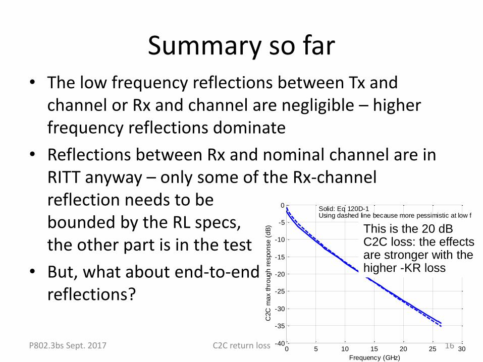
Summary so far• The low frequency reflections between Tx and
channel or Rx and channel are negligible – higher frequency reflections dominate
• Reflections between Rx and nominal channel are in RITT anyway – only some of the Rx-channel reflection needs to be bounded by the RL specs, the other part is in the test
• But, what about end-to-endreflections?
P802.3bs Sept. 2017 C2C return loss 160 5 10 15 20 25 30-40
-35
-30
-25
-20
-15
-10
-5
0
Frequency (GHz)
C2C
ma
x t
hro
ug
h r
espo
nse (
dB
)
Solid: Eq 120D-1Using dashed line because more pessimistic at low f
This is the 20 dB C2C loss: the effects are stronger with the higher -KR loss
0 5 10 15 200
0.05
0.1
0.15
0.2
0.25
0.3
0.35
0.4RL * channel IL
2 * RL
Frequency (GHz)
RL *
IL2
*R
L (
V/V
)
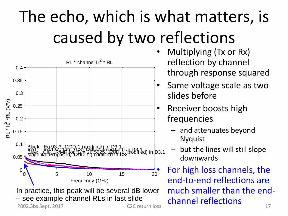
Black: Eq 93-3, 120D-1 (modified) in D3.1Red: Eq 137–1 in D1.3, 120D-1 (modified) in D3.1Blue: OIF LR/MR for fB = 26.5625, 120D-1 (modified) in D3.1Magenta: Proposed, 120D-1 (modified) in D3.1
The echo, which is what matters, is caused by two reflections
• Multiplying (Tx or Rx) reflection by channel through response squared
• Same voltage scale as two slides before
• Receiver boosts high frequencies– and attenuates beyond
Nyquist
– but the lines will still slope downwards
• For high loss channels, the end-to-end reflections are much smaller than the end-channel reflections
P802.3bs Sept. 2017 C2C return loss 17
In practice, this peak will be several dB lower – see example channel RLs in last slide
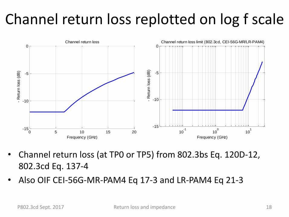
• Channel return loss (at TP0 or TP5) from 802.3bs Eq. 120D-12, 802.3cd Eq. 137-4
• Also OIF CEI-56G-MR-PAM4 Eq 17-3 and LR-PAM4 Eq 21-3
Channel return loss replotted on log f scale
18Return loss and impedanceP802.3cd Sept. 2017
0 5 10 15 20-15
-10
-5
0
Frequency (GHz)
- R
etu
rn l
oss (
dB
)
Channel return loss
10-1
100
101
-15
-10
-5
0
Frequency (GHz)
- R
etu
rn l
oss (
dB
)
Channel return loss limit (802.3cd, CEI-56G-MR/LR-PAM4)
From OIF2017.166.03
P802.3cd Sept. 2017 Return loss and impedance 19
10-1
100
101
102
-60
-50
-40
-30
-20
-10
0
Frequency (GHz)
- R
etur
n lo
ss (
dB)
Channel return loss limit (802.3cd and CEI-56G-LR)
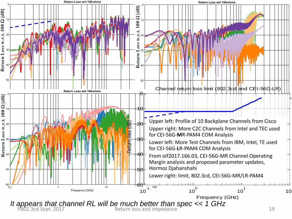
Upper left: Profile of 10 Backplane Channels from Cisco
Upper right: More C2C Channels from Intel and TEC used for CEI-56G-MR-PAM4 COM Analysis
Lower left: More Test Channels from IBM, Intel, TE used for CEI-56G-LR-PAM4 COM Analysis
From oif2017.166.03, CEI-56G-MR Channel Operating Margin analysis and proposed parameter updates, Hormoz Djahanshahi
Lower right: limit, 802.3cd, CEI-56G-MR/LR-PAM4
It appears that channel RL will be much better than spec << 1 GHz