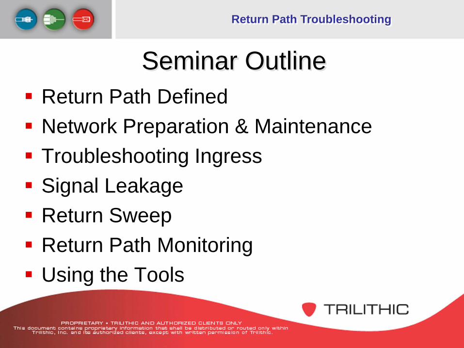
Seminar Outline Return Path Defined Network Preparation & Maintenance Troubleshooting Ingress Signal Leakage Return Sweep Return Path Monitoring Using the Tools
Return Path Troubleshooting
Return Path Defined
Return Path Troubleshooting
Return Path The focus of the cable industry is on making cable
networks quality, interactive, and two-way communications pipelines
Many services are being considered or deployed for the return spectrum including– High-speed data– Interactive TV applications– Telephony– Internet TV– Video Conferencing– And more…
Return Path Troubleshooting
Return Path The problems that operators are having
with the return path typically comes from noise and ingress Ingress is the most common problem that
operators of two-way services are struggling with
Return Path Troubleshooting
How Testing Helps Must be quick to identify, isolate, and solve
problems – know system health Provides long-term retention
– Recruiting customers is expensive and is critical to the ROI
– Loss of voice customer may also mean loss of the rest of the triple-play revenue
Physical Network Preparation & Maintenance
Return Path Troubleshooting
Enhanced Testing and Maintenance Before the service is rolled out
– Align and test each node to assure operating margin for optimal quality
Adequate digital video and HSD performance does not guarantee adequate VoIP performance– these services are relatively robust– able to withstand interference that causes
packet loss and jitter
Presenter
Presentation Notes
The addition of VoIP service to the menu of cable offerings means that an enhanced level of testing and maintenance is required. Before the service is rolled out, each node should be aligned and tested to assure an operating margin that will permit optimal quality. A cable network may be carrying digital video and high-speed data without a significantly high number of service calls, because these services are relatively robust, and are able to withstand interference that causes packet loss and jitter.
Return Path Troubleshooting
Alignment & Maintenance Required In order to provide the highest quality service and
mitigate service calls The return path should be swept and balanced Verify carrier-to-noise ratio operating margin Ingress and impulse noise must be monitored for
at least a 24-hour period – occurs at various times of the day– has a wide variety of causes
Presenter
Presentation Notes
In order to provide the highest quality service and mitigate service calls, the return band must be properly aligned and maintained. There are a number of practices used to ensure proper alignment, which should be performed upon the activation of any new installation on the network. The return path should be swept and balanced to ensure that it is operating according to design. It is also essential to test to verify that there is sufficient operating margin with regard to carrier-to-noise ratio. Because ingress and impulse noise can occur at different times of the day, and by a wide variety of causes, it must be monitored for at least a 24-hour period. The monitoring system used for this can be used to prepare the node for certification, then to actually certify the node, and then to maintain the node as an aid to locate problems before they impact the subscriber. A goal is to achieve a “carrier-to-crud” ratio of >40dB.
Return Path Troubleshooting
Return Path Impact of Noise & Ingress on System Services
Required System Maintenance– Return Sweeping – Ingress Troubleshooting – Alternative Maintenance Techniques
Required Monitoring – Monitoring of the Spectrum– Correlating Monitoring information with system performance
Presenter
Presentation Notes
Setting up of: • Fiber Link • RF Distribution • Test Equipment Maintenance Includes: • Amplifier alignment • Installation Testing • Ingress Monitoring Troubleshooting Includes: • Pin Pointing Ingress
Return Path Troubleshooting
Primary sources of return path noise Thermal Noise
– generated in each active component Fiber Optic-Noise
– From the Return Path Laser – Fiber Optic Receiver
Ingress– Discrete– Broadband– System Induced
Return Path Troubleshooting
System Operating Levels C/N Margins may be improved by raising
Carrier Levels - But Only to a Point Carrier Levels are limited by the Return
Laser
Return Path Troubleshooting
Troubleshooting Ingress
Return Path Troubleshooting
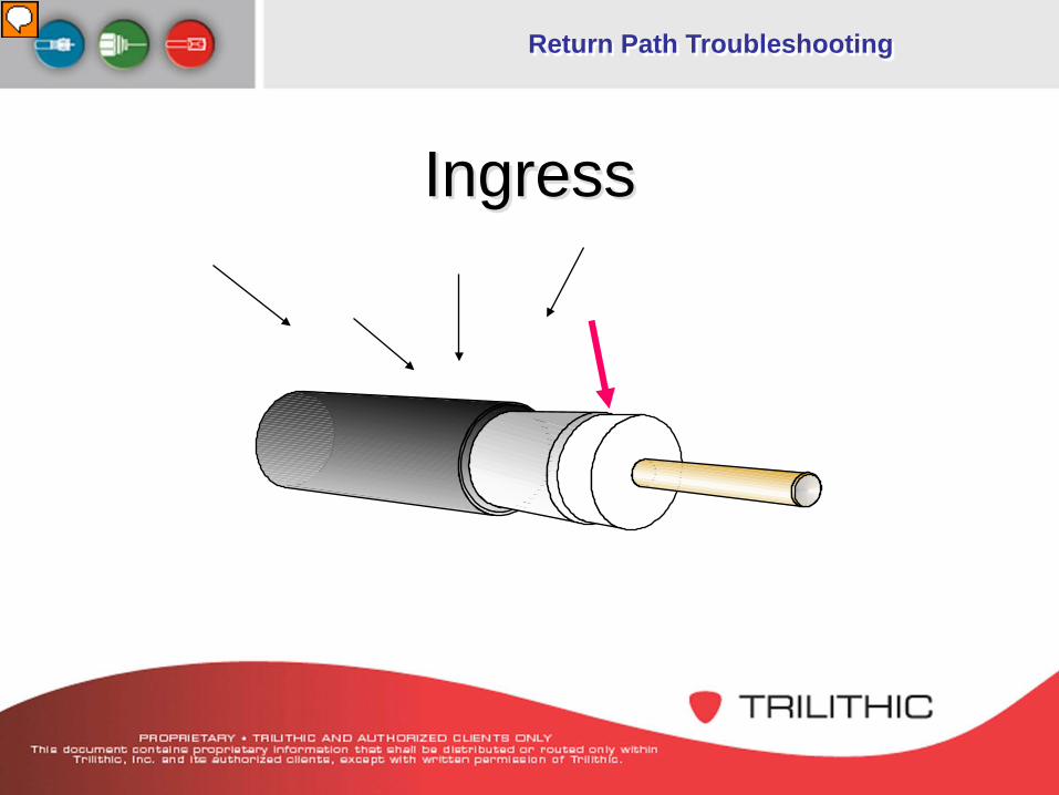
Ingress
Presenter
Presentation Notes
There is a direct relationship between Leakage and Ingress If signals can leak out of your system, off-air signals can leak into your system. The degree of ingress is determined by Signal leakage amplitude vs Off-air signal amplitude.
Return Path Troubleshooting
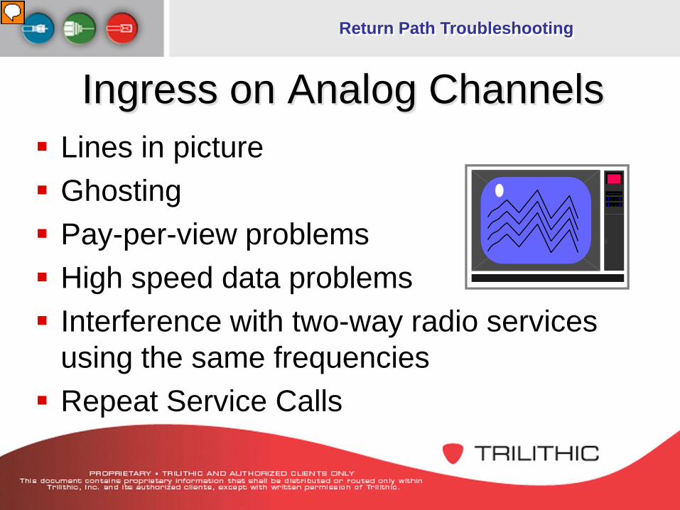
Ingress on Analog Channels Lines in picture Ghosting Pay-per-view problems High speed data problems Interference with two-way radio services
using the same frequencies Repeat Service Calls
Presenter
Presentation Notes
Interference to a customer’s analog pictures can be identified as: Ghosting or black vertical bars in the TV picture. This occurs when the same program on the same channel is ingressing into the cable or TV set. “S” shaped or diagonal lines in the TV picture. This occurs when a different program on the same channel is ingressing into the cable or TV set. Intermittent lines in the picture and possibly audio buzz. Possible causes are: - CB radio effecting channel 5 - Local pager services effecting channels 19 & 20 - Ham radio effecting 5-40 MHz return band and 550-750 MHz band
Return Path Troubleshooting
Ingress on Digital Channels Macro Blocking (Tiling) Freeze Frame Picture and Sound go to black Robotic Voice Data Packet Loss or slower speeds Repeat Service Calls
Presenter
Presentation Notes
Interference to a customer’s digital pictures can be identified as: Mosaic - This happens when ingress has created marginal Bit Error causing the loss of a packet(s) of video compression data Freeze frame - This happens when ingress has created significant Bit Error causing the loss of an entire refresh frame Loss of picture and sound to black - This happens when ingress is severe enough to completely destroy a data stream into unusable garbage.
Return Path Troubleshooting
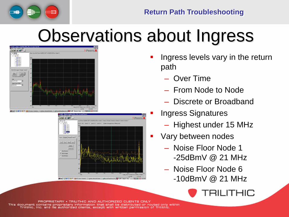
Observations about Ingress Ingress levels vary in the return
path– Over Time– From Node to Node– Discrete or Broadband
Ingress Signatures– Highest under 15 MHz
Vary between nodes– Noise Floor Node 1
-25dBmV @ 21 MHz– Noise Floor Node 6
-10dBmV @ 21 MHz
Return Path Troubleshooting
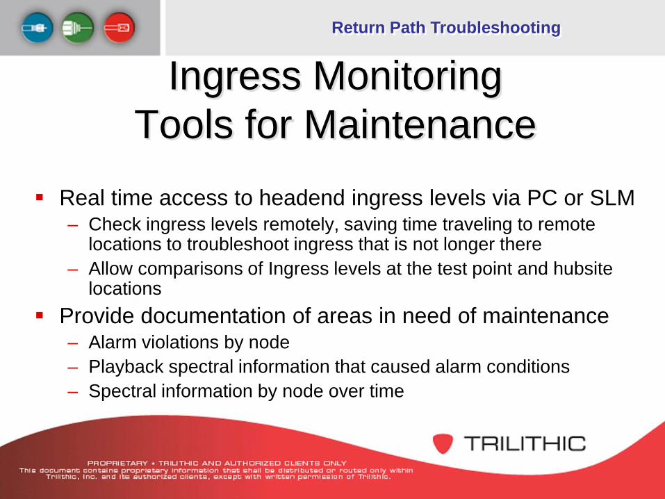
Ingress MonitoringTools for Maintenance
Real time access to headend ingress levels via PC or SLM– Check ingress levels remotely, saving time traveling to remote
locations to troubleshoot ingress that is not longer there – Allow comparisons of Ingress levels at the test point and hubsite
locations Provide documentation of areas in need of maintenance
– Alarm violations by node– Playback spectral information that caused alarm conditions– Spectral information by node over time
Return Path Troubleshooting
Common Sources of Ingress Off Air
– Short Wave Radio (4.75 to 10 MHz)– Ham Operators (7, 10, 14, 18, 21, 24 & 28 MHz)– CB Radios (27 MHz)– Broadband noise (things with electric motors, PCs, etc)– Impulse Noise (shorts bursts of Broadband noise)
Plant Induced– Common Path Distortion (6MHz beats across entire spectrum)– Transient Hum Modulation – Excessive Gain
Subscriber Induced– Direct Pickup– Malfunctioning Subscriber Devices– Broadband noise from appliances– Self Installs
Return Path Troubleshooting
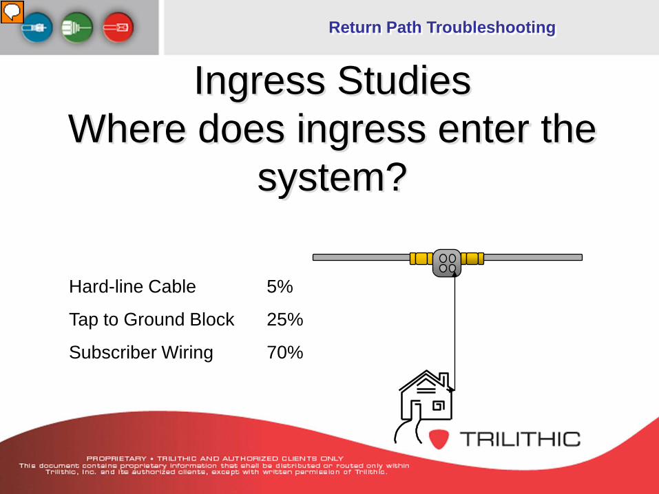
Ingress Studies Where does ingress enter the
system?
Hard-line Cable 5%
Tap to Ground Block 25%
Subscriber Wiring 70%
Presenter
Presentation Notes
Ingress • From Cable Labs Study - Most Ingress enters from the subscriber premise • Improperly installed connectors • Unterminated splitters • Direct Pickup from Television set
Return Path Troubleshooting
The Daily Routine Make a cross reference of service groups (router
card/blades) and system nodes Compare trouble tickets from HSD, IPPV and Telephony
to determine problem nodes Use alarm information from status monitoring system to
verify if service degradation is due to ingress Use remote access through a PC or connect a spectrum
analyzer to system test points and verify the problem still exists
Return Path Troubleshooting
The Daily Routine Utilize good installation practices Install devices need to be of a good quality Conduct pre and post reverse testing on installations Monitor and repair signal leakage Check the performance of the return path Issue the reverse trouble tickets to the techs
Potentially one bad drop cable or one poor connection can wipe out an entire node for reverse services.
Return Path Troubleshooting
Signal Leakage
Return Path Troubleshooting
What is Signal Leakage? Definition:
– Undesired emission of signals out of an HFC network
Presenter
Presentation Notes
What is signal leakage? The undesired emission of signal out of an HFC network. We monitor a specific frequency for signal leakage However: 1.) If you leak one you are leaking all frequencies 2.)All frequencies do not leak at the same amplitude. 3.)Leaks become worse over time. 4.)Leakage is evasive, measurements taken at the same location at different times do not always produce the same readings. We will discuss how leakage can be: Dangerous - to aero-navigational users Disruptive - to off-air broadcasters Destructive - to the physical condition of the plant if left unrepaired
Return Path Troubleshooting
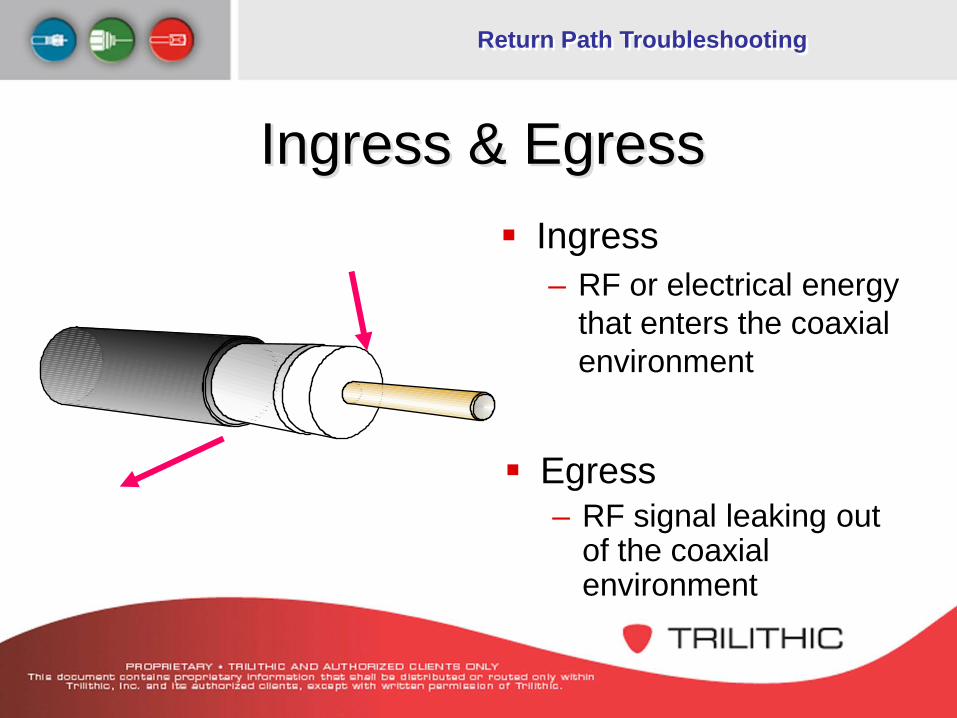
Ingress & Egress Ingress
– RF or electrical energy that enters the coaxial environment
Egress – RF signal leaking out
of the coaxial environment
Return Path Troubleshooting
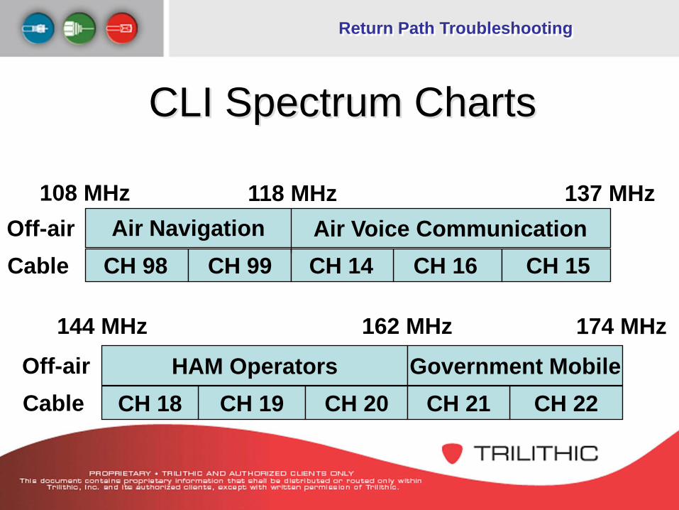
CLI Spectrum Charts
108 MHzOff-airCable
Air NavigationCH 98 CH 99 CH 14 CH 15CH 16
Air Voice Communication118 MHz 137 MHz
HAM OperatorsCH 19CH 18 CH 22CH 20 CH 21
Government Mobile
174 MHz144 MHz 162 MHz
Off-airCable
Return Path Troubleshooting
Common Causes 70% of all leakage is caused by problems
between the tap and entry to the house – Aging and environmental stress– Physical trauma to cables or connectors– Loose drop connectors– Inferior quality coaxial cable, passives, or
connectors– Loose hard line connectors
Presenter
Presentation Notes
Common causes: - cracks in cable - corroded or loose connectors - loose device enclosures
Return Path Troubleshooting
Other Causes of Leakage Improperly installed connectors Cracks in the trunk and feeder cable Animal chews Poorly-shielded drop cable Bad connectors at the tap Bad/loose port terminator Corroded connectors
Presenter
Presentation Notes
Unusual causes: - squirrel chewing on hardline coax - dog chewing RG coax - puncture in coax at midspan locations clamps without the use of spacers tree branch rubbing or falling on cable projectiles - gunshots, arrows, pellets, etc. vandalism - customer caused leakage use of antenna on A/B switch illegal outlets using inferior materials tampering with settop box
Return Path Troubleshooting
Other Causes Continued Customer installed equipment Damaged amplifier housing or loose
amplifier housing lids Broken tap ports Poor installation of splices and connectors Poorly-shielded customer
premise equipment
Return Path Troubleshooting
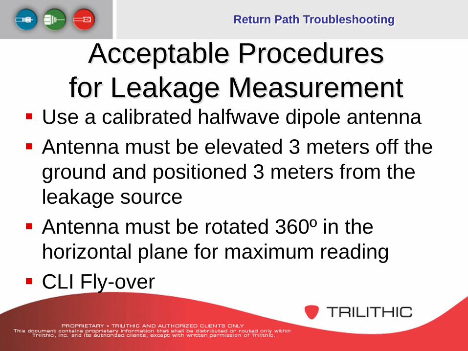
Acceptable Procedures for Leakage Measurement
Use a calibrated halfwave dipole antenna Antenna must be elevated 3 meters off the
ground and positioned 3 meters from the leakage source Antenna must be rotated 360º in the
horizontal plane for maximum reading CLI Fly-over
Return Path Troubleshooting
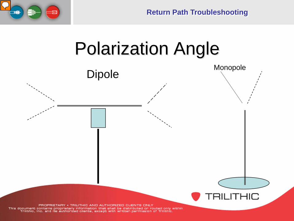
Polarization AngleDipole
Monopole
Presenter
Presentation Notes
Leakage signals are normally at their highest amplitude in the horizontal plane. This is probably due to the fact that most of the cable plant is in a horizontal position. The FCC requires the use of a horizontal dipole antenna to make CLI compliance measurements. This would be to optimize the leakage signal reading by matching the polarization plane. However, it is required to rotate the dipole antenna to match the polarization angle for peak amplitude readings. For “Find and Fix” maintenance purposes, a vertical whip antenna is preferred because of its omni-directional properties vs. the directional properties of a dipole. Peaking a dipole antenna on a moving vehicle would be impractical. With a handheld leakage detector, you would be rotating the “rubber duck” antenna from a vertical to horizontal plane, looking to maximize the peak amplitude reading and determine the direction and ultimately the location of a leak.
Return Path Troubleshooting
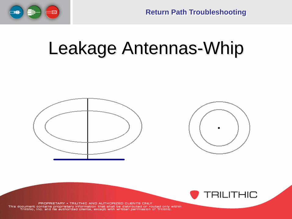
Leakage Antennas-Whip
Return Path Troubleshooting
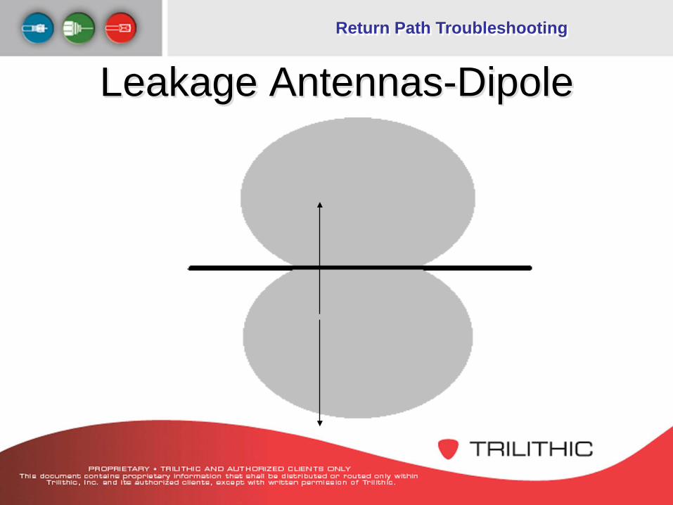
Leakage Antennas-Dipole
Return Path Troubleshooting
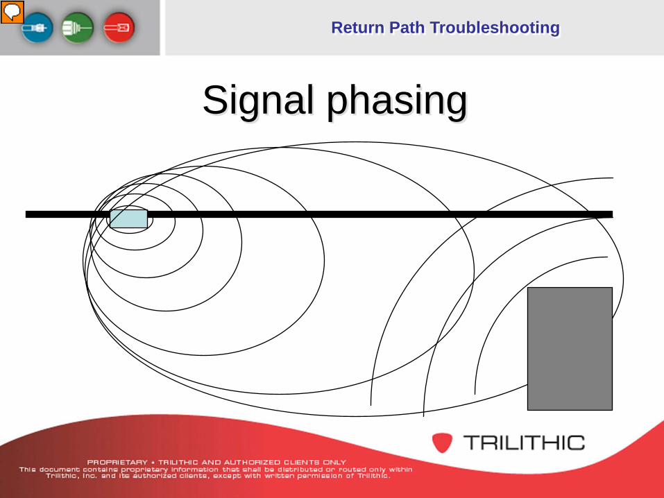
Signal phasing
Presenter
Presentation Notes
Radiated signals can: 1.) Reflect off surfaces `2.) Travel on conductive surfaces 3.) Occur from more than one nearby location These “Multipath” signals arrive at the leakage receiver at different times but at the same frequency. These multipath signals can combine inside the leakage receiver and cause a time relationship problem which may add to or cancel from the signal amplitude reading, depending on the phase relationship. Being aware of potential multipath conditions is the only thing a technician can do. Awareness of such condition would encourage the technician make extra effort in properly peaking the antenna.
Return Path Troubleshooting
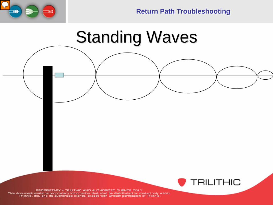
Standing Waves
Presenter
Presentation Notes
As stated before, leakage signals can travel down a conductive path to ground. In most cases this conductive path will be the strand wire or the coaxial sheath. The technician should continue monitoring a leak until a peak reading is made.
Return Path Troubleshooting
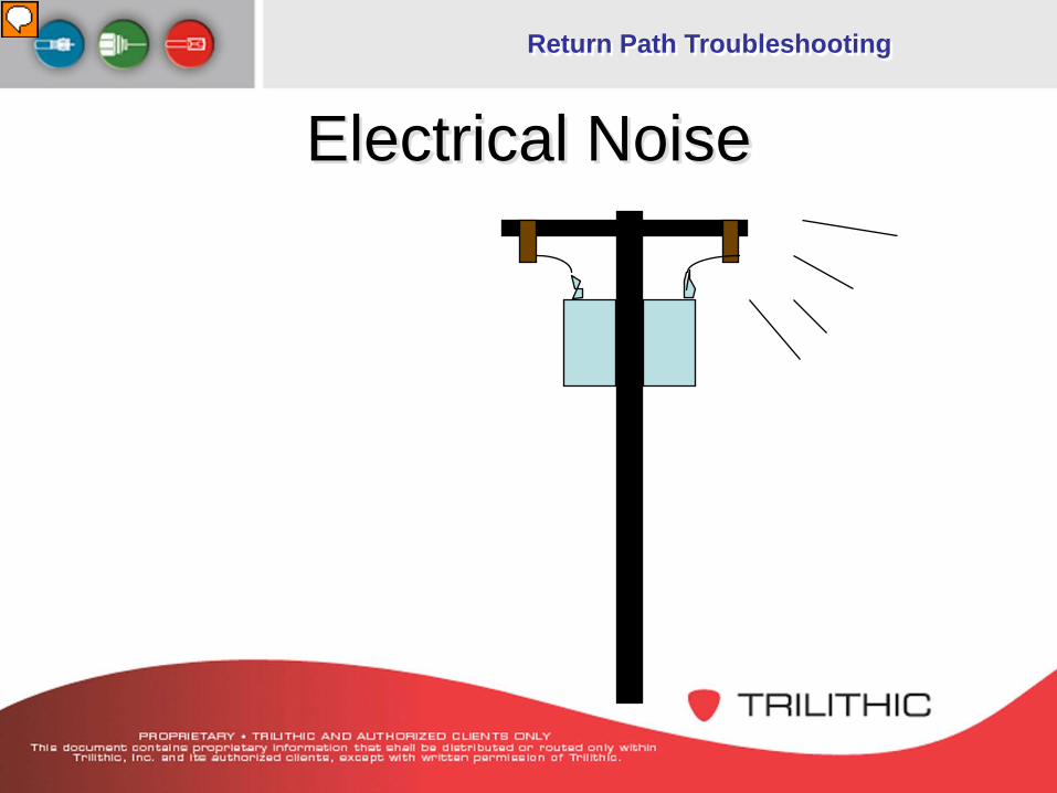
Electrical Noise
Presenter
Presentation Notes
Electrical noise is an interesting annoyance to the leakage technician. In most cases, electrical noise is caused by “spark gap energy” at power line insulators. This energy can manifest itself as RF! This spark gap energy (RF) may reach the leakage frequency range and cause a buzzing noise on the audio circuit of a leakage detector. Channel tagging usually eliminates this problem.
Return Path Troubleshooting
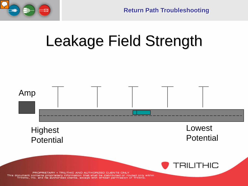
Leakage Field Strength
HighestPotential
LowestPotential
Amp
Presenter
Presentation Notes
Consider an amplifier the transmitter.... Consider leakage points along the cable as antennas.... Result:The antennas closest to the transmitter have the highest potential for power. Leakage amplitude is determined by: - the available signal level in the coax at the point of leakage. - the severity of the physical condition causing the leak.
Return Path Troubleshooting
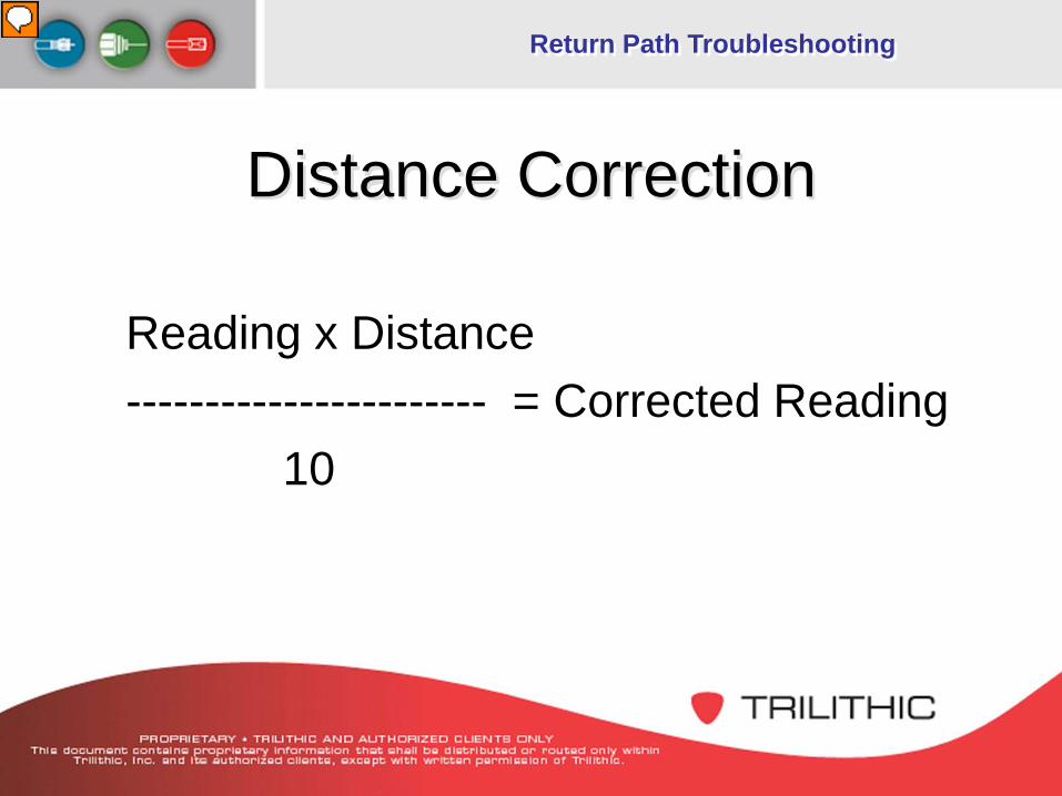
Distance Correction
Reading x Distance----------------------- = Corrected Reading
10
Presenter
Presentation Notes
Why would you want to know the leakage level from a 10 foot distance? The FCC states: Leaks greater than 20uV/m at 10 feet shall be logged and then repaired within a reasonable period of time. Note the measurement reference is at a 10 foot distance from the plant. This distance correction formula will aid in determining the repair priority of a leak. At this point it would be well to note that many operating companies commonly have more stringent requirements than the FCC.
Return Path Troubleshooting
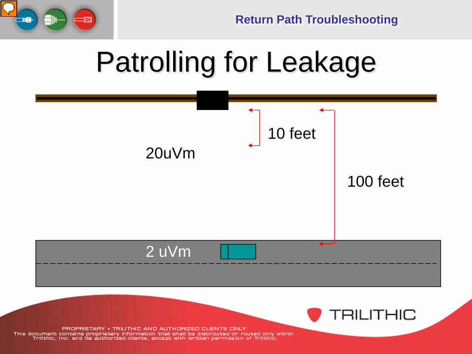
100 feet
10 feet20uVm
2 uVm
Patrolling for Leakage
Presenter
Presentation Notes
Pinpointing sources of leakage can at times seem to be more of an art than a science. Patrolling the system: The first indication of leakage will be very short tone pulses from the leakage receiver. These will be followed by longer pulses eventually changing to a continuous tone if the leakage is strong enough. Relying solely on the audio indication, drive the vehicle until the tone starts to decay. Mentally mark the peak tone indication and return to that area for further investigation. Note: best result at at patrolling speeds of under 25 MPH. Apply distance correction formula: This will help determine the priority of the leakage repair.
Return Path Troubleshooting
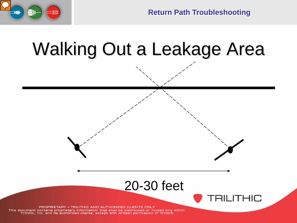
Walking Out a Leakage Area
20-30 feet
Presenter
Presentation Notes
Walking the area: Use the rubber duck antenna or near-field probe to find the exact source of the leakage. The near-field probe is especially useful in congested mechanical areas, such as multi-connector housings and MDU locations. If the leakage amplitude is greater than the threshold setting on the leakage detector, an audible tone will sound from the detector. Listen for the audible pitch of the leakage detector to rise from the increasing signal amplitude as you get closer to the leakage source. Optional: In areas where it is difficult to determine the direction of a leak, the technician can use a dipole antenna to triangulate the leakage source. If necessary, use the near-field probe to literally touch suspected points of leakage. When many connectors are within close proximity of each other, using the near-field probe will help determine which connector(s) is the cause of leakage.
Return Path Troubleshooting
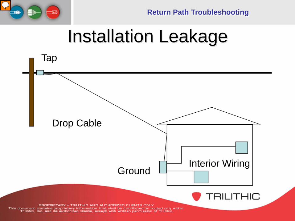
Installation Leakage
Drop Cable
Tap
GroundInterior Wiring
Presenter
Presentation Notes
Use the following procedure to determine the source of signal leakage at the subscriber location. 1.)Disconnect the drop from the tap and terminate the port to determine if the leakage source is caused by the customer installation. 2.)If the audio tone stops, reconnect the drop to the tap and disconnect the drop and the ground block. Terminate the ground block. 3.)If the audio tone is present, examine the ground block and the condition of the drop cable. 4.)If the audio tone stops, reconnect the drop and examine the home wiring and settop connections.
Return Path Troubleshooting
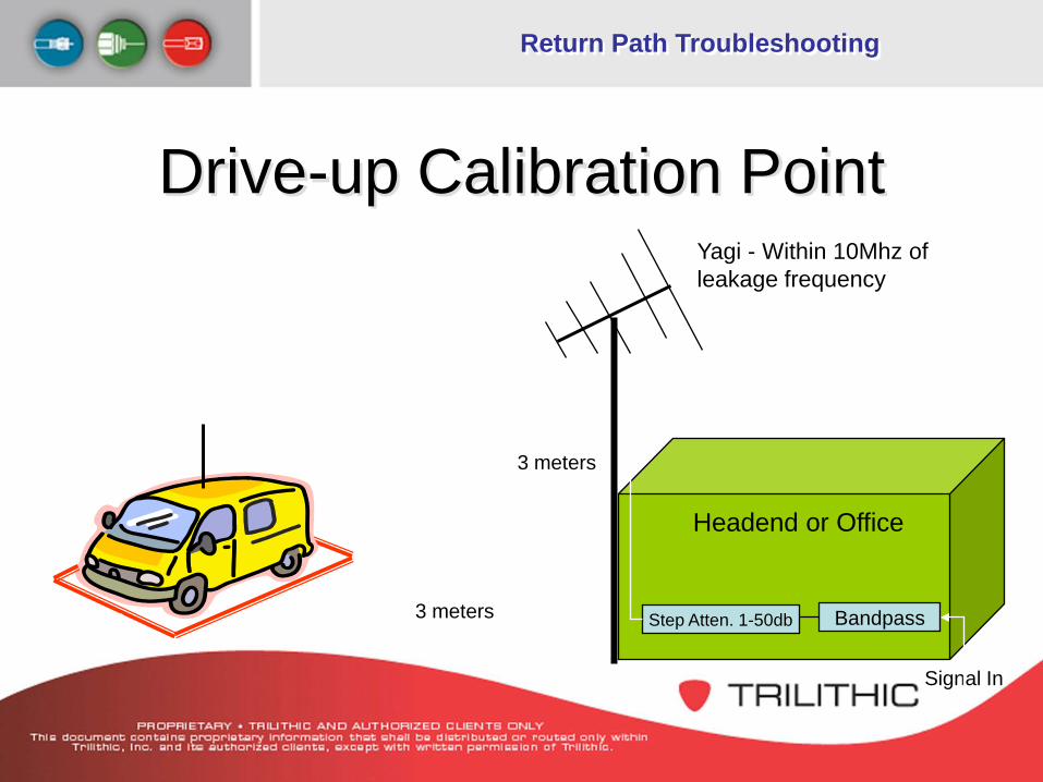
BandpassStep Atten. 1-50db
Headend or Office
Drive-up Calibration PointYagi - Within 10Mhz of leakage frequency
3 meters
3 metersMarked Area
Signal In
Return Path Troubleshooting
Why and How to Check forLeakage ?
Return Path Troubleshooting
Public Safety–Potential interference with aircraft
communication/navigation–The cable system could interfere with off-air
signals Quality of Service
–Ingress impairs picture quality–Ingress/Egress (leakage) usually is a sign
of a pending equipment failure
Return Path Troubleshooting
Increased implementation of services requiring return path activation–If a system has egress it will most likely
have ingress–Ingress brings the viability of two-way
services into question–VoIP demands higher network reliability
Return Path Troubleshooting
Common Leakage Sources Splices and fittings- Water and weather can result
in pulled out, loose or corroding fittings Splices at taps, line extenders, splitters, amps and
passive devices, house amplifiers, poor or no connectors, and improperly terminated splitters
15% jumpers from drops to taps or ground blocks 75% of leaks come from subscribers home
Return Path Troubleshooting
Return Sweep
Return Path Troubleshooting
Return Sweep Proper alignment of the system is critical to
service quality and reliability Problems uncovered while sweeping can
also cause ingress– Bad, or loose connections– Cable damage– Misalignment (can cause
laser clipping)
Presenter
Presentation Notes
This feature adds value to the monitoring equipment in the NOC by helping the tech perform preventive maintenance.
Return Path Troubleshooting
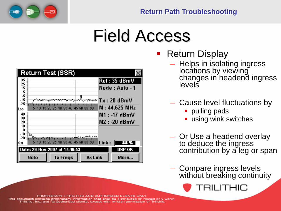
Field Access Return Display
– Helps in isolating ingress locations by viewing changes in headend ingress levels
– Cause level fluctuations by pulling pads using wink switches
– Or Use a headend overlay to deduce the ingress contribution by a leg or span
– Compare ingress levels without breaking continuity
Return Path Troubleshooting
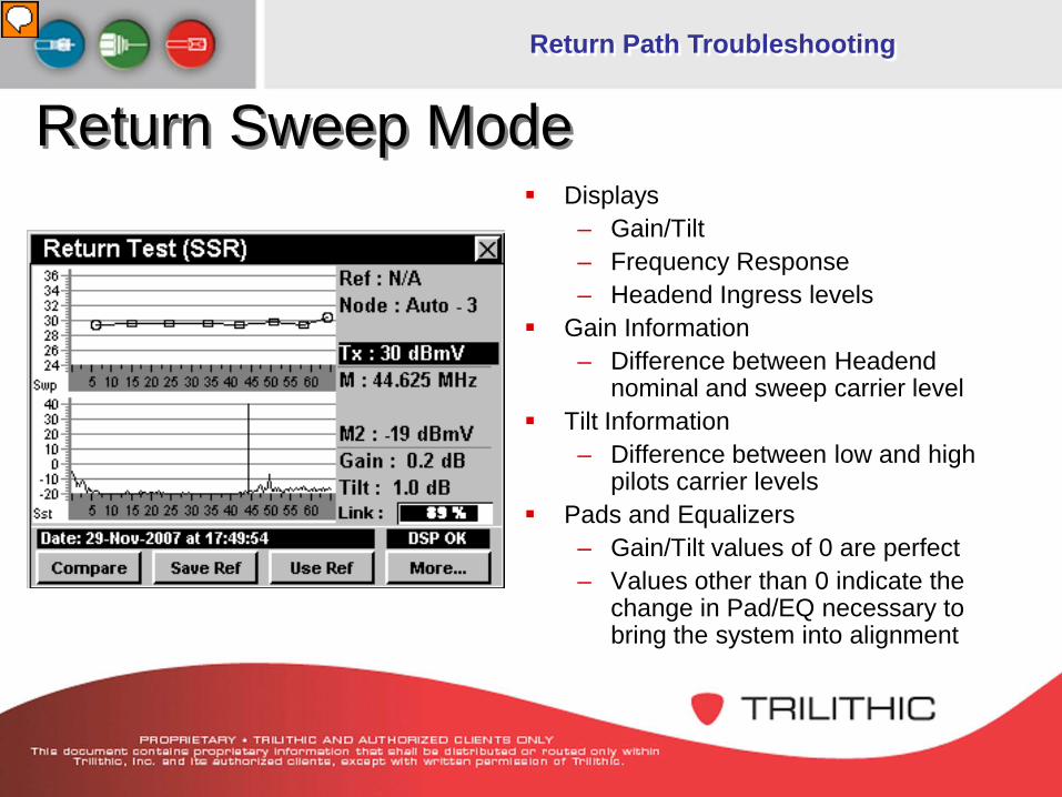
Return Sweep Mode Displays
– Gain/Tilt – Frequency Response – Headend Ingress levels
Gain Information – Difference between Headend
nominal and sweep carrier level Tilt Information
– Difference between low and high pilots carrier levels
Pads and Equalizers – Gain/Tilt values of 0 are perfect– Values other than 0 indicate the
change in Pad/EQ necessary to bring the system into alignment
Presenter
Presentation Notes
Balancing of System Amps • Sweep Signals transmitted by field unit are recovered and analyzed at headend -Gain, Tilt and Frequency Response of sweep carriers are returned to the field unit via a downstream telemetry carrier • Start at node - verify unit gain at headend by injecting directly into laser - align RF portion of node by injecting into upstream test point • Store Reference trace (if applicable) • Proceed to next station Headend Unit Setup • Set input level to sweep receiver • Set Sweep Frequencies (if applicable) • Avoid Occupied Bands • Set downstream telemetry Frequency and Level • Usually 10 dB down from video • Multiple Nodes may be combined into the sweep receiver providing the combined noise is about 20 dB from the RX level High Noise Levels • Usually caused by excessive gain • Poor system integrity Remedies: - Combine few nodes into the sweep receivers input - Split the nodes over more inputs (if applicable) - balance the system in smaller sections - remove feeder - balance trunk first
Return Path Troubleshooting
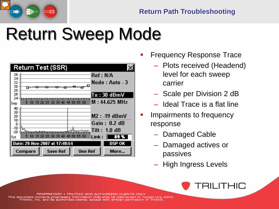
Return Sweep Mode Frequency Response Trace
– Plots received (Headend) level for each sweep carrier
– Scale per Division 2 dB– Ideal Trace is a flat line
Impairments to frequency response– Damaged Cable – Damaged actives or
passives– High Ingress Levels
Presenter
Presentation Notes
Balancing of System Amps • Sweep Signals transmitted by field unit are recovered and analyzed at headend -Gain, Tilt and Frequency Response of sweep carriers are returned to the field unit via a downstream telemetry carrier • Start at node - verify unit gain at headend by injecting directly into laser - align RF portion of node by injecting into upstream test point • Store Reference trace (if applicable) • Proceed to next station Headend Unit Setup • Set input level to sweep receiver • Set Sweep Frequencies (if applicable) • Avoid Occupied Bands • Set downstream telemetry Frequency and Level • Usually 10 dB down from video • Multiple Nodes may be combined into the sweep receiver providing the combined noise is about 20 dB from the RX level High Noise Levels • Usually caused by excessive gain • Poor system integrity Remedies: - Combine few nodes into the sweep receivers input - Split the nodes over more inputs (if applicable) - balance the system in smaller sections - remove feeder - balance trunk first
Return Path Troubleshooting
Return Path Monitoring
Return Path Troubleshooting
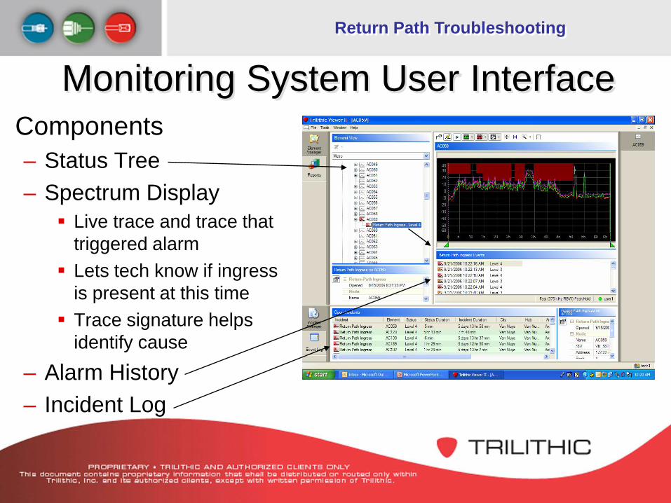
Monitoring System User InterfaceComponents– Status Tree– Spectrum Display
Live trace and trace that triggered alarm
Lets tech know if ingress is present at this time
Trace signature helps identify cause
– Alarm History– Incident Log
Return Path Troubleshooting
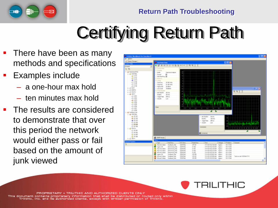
There have been as many methods and specifications
Examples include– a one-hour max hold– ten minutes max hold
The results are considered to demonstrate that over this period the network would either pass or fail based on the amount of junk viewed
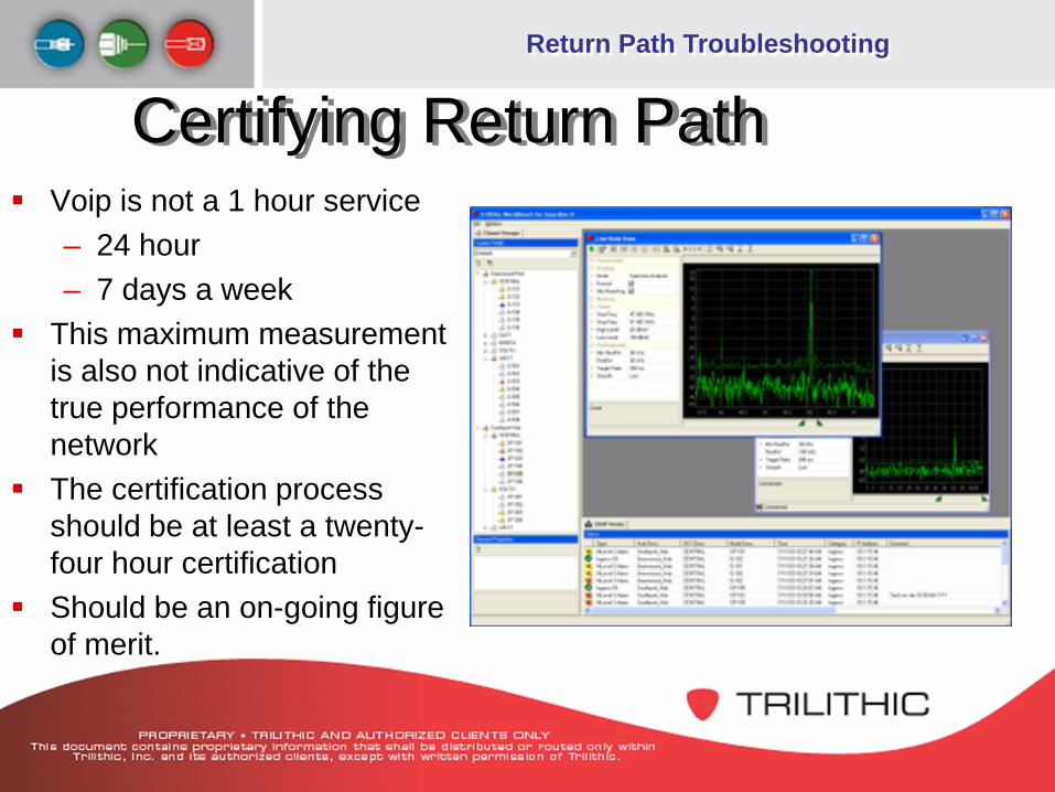
Certifying Return Path
Return Path Troubleshooting
Voip is not a 1 hour service– 24 hour– 7 days a week
This maximum measurement is also not indicative of the true performance of the network
The certification process should be at least a twenty-four hour certification