Embed Size (px)
Citation preview

Review: Active Control of Shock-associated
Unsteady Flow Phenomena in Aeroengines
- Suppression Techniques for Transonic Cascade Flutter and
Supersonic Jet Noise -
Toshinori Watanabe
Department of Aeronautics and Astronautics
The University of Tokyo
Tokyo, Japan
Abstract
Active control techniques for cascade flutter suppression and supersonic jet
noise reduction were studied in the University of Tokyo. For flutter suppression,
piezoelectric devices were installed on the blade surfaces. The active oscillation
of the trailing edge of a blade was found to suppress the flutter instability in the
numerical analysis. The effect was qualitatively confirmed in a trial experiment.
For jet noise reduction, the technique of microjet injection was experimentally
studied. The microjet could provide quite effective reduction of shock associated
noise through the suppression of jet oscillation. The present paper briefly intro-
duces these studies.
1. Introduction
Active control of unsteady flow is thought to be one of the key issues for fu-
ture environmentally-friendly aeroengines with ultra-high reliability and efficien-
cy. Recently, the active suppression techniques of transonic cascade flutter and
supersonic jet noise were proposed and studied in the University of Tokyo.
For suppression of cascade flutter, a control method with active oscillation on
the blade trailing edge was proposed, and feasibility study was performed with a
developed numerical method with flow-structure coupling under transonic flow
condition (1)
. The active oscillation of the trailing edge was realized by use of
piezoelectric device (2)
. From the numerical results, the control method was
confirmed effective if the phase difference between the original blade vibration
and the active trailing edge oscillation was adequately selected. A trial experiment
was also performed in a subsonic flow to verify that the active trailing edge
oscillation with piezoelectric device could generate effective unsteady
aerodynamic force for changing blade vibration stability (3)
. Since the stable
vibration range in the inter blade phase angle was found to be slightly but
substantially widened, the control technique seemed promising for future
application for flutter suppression.
For suppression of supersonic jet noise, the technique of microjet injection
was experimentally examined (4), (5)
. A high aspect-ratio rectangular nozzle was
adopted as the jet nozzle based on the expectation that the combination of non-
circular nozzle and microjet injection could be effective for reduction of

supersonic jet noise. The nozzle was equipped with forty-four evenly spaced
micro-nozzles at the long sides of the nozzle exit. Far-field acoustic
measurements were conducted for widely ranged microjet conditions to
understand the influence of the microjet on characteristics of supersonic jet noise
as well as the flow field. For understanding the unsteady behavior of jet and shear
layer, flow visualization was performed with schlieren technique using a high-
speed camera. A remarkable noise reduction was found in the acoustic data, and
the dramatic change in the unsteady flow behavior was observed in the flow
visualization.
In the present paper, the results of these two studies are reviewed to show the
possibility of active control for future aeroengines.
2. Suppression of Cascade Flutter with Piezoelectric Device
2.1 Numerical Analysis
A developed code of flow-structure coupling method was used for the
numerical analysis. The unsteady aerodynamic force acted on all blades was
calculated in the flow computation based on the 2D Euler equations. The obtained
unsteady aerodynamic force was introduced into the structural computation. The
structural model of the blade was a simple one of a translational mode. In the
structural computation, the equation of motion of the blade was solved with
Runge-Kutta-Gill scheme to obtain the blade displacement. The lift force on the
blade calculated in the flow computation was introduced into the equation of
motion of the blade, and the computed blade displacement was used for
generation of new grid coordinates in the following time step of flow
computation. The structural damping was neglected for focusing on the
aerodynamic damping effect.
The two-dimensional non-linear Euler equations were solved with a second
order upwind TVD scheme. The incorporated Euler iteration introduced second
order accuracy in time. The inviscid computation was performed based on the
knowledge that the dominant factor of the vibration instability was the unsteady
aerodynamic force induced by the oscillation of passage shock wave for the
adopted cascade model.
The computational domain, numerical grid (H-O-H configuration) and
boundary conditions are shown in Fig. 1. At the inlet boundary, the total pressure,
the total temperature, and the tangential velocity were fixed. The static pressure
was specified at the outlet boundary, and the blade surfaces were treated as slip
walls.
The tip section of Quiet Fan B in NASA Quiet Engine Program (6)
was adopt-
ed as a model cascade. The inlet Mach number was 1.25, and the pressure ratio pr
was 1.7. The passage shock movement was known to be dominant for blade vi-
bration stability in the adopted case (7)
. Figure 2 shows the computed steady Mach
contour diagram. A passage shock is generated at the trailing edge of each blade,
and its oscillation due to blade vibration induces unsteady aerodynamic force on
the pressure surface of the neighboring blade.
Figure 3 describes the proposed active control method. Since the vibration

Fig.1 Computational Domain, Grid and Boundary Conditions
Fig.2 Mach Contour Diagram Fig.3 Trailing Edge Oscillation
(Inlet Mach 1.25, Interval 0.05)
stability is supposed to be changed by the active control of passage shock move-
ment, the trailing edge of the blade is actively oscillated like a flap. The trailing
edge oscillation can be realized by use of piezoelectric devices. The blade vibra-
tion due to the shock oscillation and the active trailing edge oscillation by piezoe-
lectric device are separately considered.
Four flow channels were used in the computation to simulate the inter blade
phase angle, , of 90 degrees, which corresponded to an unstable condition of the
cascade flutter. The reduced frequency, k, was 0.086 based on the chord length of
blade and inlet velocity. All blades were set stationary in the initial situation, and
Flow

a sinusoidal disturbance was given to the axial velocity at the inlet boundary dur-
ing the time ts, a period of blade natural oscillation.
The activation timing of the control was determined based on the total energy,
E, of a blade. The total energy is composed of kinetic energy and elastic energy of
a blade. In the time period when E is larger than a specified threshold value, E0,
the trailing edges of blade 1 and blade 3 are actively oscillated. The amplitude of
trailing edge oscillation angle was fixed to be 0.5 degrees.
From the results, the control method was found to be effective if the phase
difference between trailing edge oscillation and blade vibration, , was adequately
set. is positive when the phase angle of trailing edge oscillation advances that of
the blade vibration. The most effective suppression was obtained when was +45
degrees. Figure 4 shows time traces of the blade displacement and unsteady
aerodynamic force acted on the blade when is +45 degrees. Solid lines indicate
the results in the case with control and the dotted lines show those in the case
without control. The shaded areas in the figures correspond to the periods when
the trailing edge oscillation is active. E0 is determined to be a value of the total
energy when the amplitude of blade oscillation is about 0.2% of the chord length.
From the comparison between the results of solid and dotted lines, the increase in
the blade displacement is seen to be effectively suppressed for both No.1
(controlled) and No.2 (non-controlled) blades by the active control of trailing
edge oscillation.
Fig.4 Time History of Blade Displacement and Unsteady Aerodynamic Force
ts

2.2 Experimental Study
The blow-down type linear cascade wind tunnel used in the experiment is
schematically shown in Fig. 5. The test section has 50 mm×100 mm rectangular
cross section. The test section and the cascade configuration are illustrated in
Fig.6. The cascade is composed of 7 Double Circular Arc (DCA) airfoil blades.
The inlet Mach number is 1.2 and the incidence angle is 0 degree. The cascade
configuration is not the same one as in the numerical study due to the limitation
of test facility. The objective of the present experiment is, accordingly, to examine
the possibility of active control on unsteady aerodynamic force in a qualitative
sense.
An example of steady flow field, visualized by shadow graph method, is
shown in Fig. 7. A leading edge oblique shock is clearly seen on each blade, and a
passage shock can be seen in blade-to-blade flow channel.
The Influence Coefficient Method was used for analyzing unsteady
aerodynamic characteristics of the oscillating blade. The central blade (No.0) was
oscillated in a translational mode by a crank mechanism, while the other blades
were stationary. The unsteady aerodynamic force induced by the oscillation of
No.0 blade was measured with strain gauge system shown in Fig. 8 on No.0
blade, and No. 1 blades. The unsteady aerodynamic work coefficient of the
blade No. n, Cf,n(), is calculated by the following equation,
nCC annf sin, (1)
where, n is the blade number, Cn is the amplitude of unsteady aerodynamic work
on each blade, and a is the phase difference between the blade displacement and
the unsteady aerodynamic force. These values are calculated through Fourier
decomposition. The unsteady aerodynamic work coefficient of each blade is
linearly superposed as Eq. (2) to obtain the unsteady aerodynamic work when all
blades are oscillating with an arbitrary inter blade phase angle.
Fig.5 Transonic Linear Cascade Wind Tunnel

Fig.6 Test Section and Cascade Configuration
Fig.7 Flow Field around Cascade
Fig.8 Measuring System for Aerodynamic Force

m
mn
nfCW , (2)
Figure 9 shows the control blade equipped with piezoelectric devices. The two
devices were glued on the suction and pressure sides of the blade. The electric
signals drove the piezo-oscillation with arbitrary frequency, and the frequency
range from 10 to 50 Hz was used in the experiment. Figure 10 shows the ampli-
tude contour of piezo-blade when AC voltage was provided on the device. Ampli-
tude at the tip section is seen to larger than that at the hub section, and the ampli-
tude at trailing edge (T.E.) is larger than that at leading edge (L.E.) over the whole
span. Though the oscillation mode was not necessarily correspondent to the nu-
merical model, the blade was used as it was in the present experiment for feasibil-
ity study of the control method.
Fig.9 Blade with Piezoelectric Device
Fig. 10 Amplitude Contour of Piezo-Blade

The piezo-blade was oscillated with the same frequency as that of the transla-
tional oscillation of blade No.0 by crank mechanism. From the measured results
of unsteady aerodynamic force, the unsteady aerodynamic work at each is cal-
culated. The influences of blade vibration and the active oscillation by piezoelec-
tric device are separately considered in the experiment because of the difficulty in
simultaneous execution of both oscillations. The unsteady aerodynamic forces
were measured separately for the case with blade vibration and for the case with
active oscillation by piezoelectric device. The measured data are superposed each
other.
The superposed unsteady aerodynamic work is plotted against the inter blade
phase angle in Fig. 11 for the case of k=0.018. The result of original case without
control is also plotted for comparison. When is 120 degrees, the superposed
aerodynamic work shows substantial reduction in unstable aerodynamic work in
the range of where the original blade vibration is unstable. The range of positive
work indicating flutter instability is shown to be slightly reduced as well. These
results indicate the stabilization effect of the active oscillation of the piezoelectric
device. On the contrary, when is -60 degrees, the blade vibration is destabilized
by the active oscillation.
2.3 Concluding Remarks
From the numerical and experimental results, the active trailing edge oscilla-
tion was found to have substantial suppression effect on flutter instability in tran-
sonic flow if the phase difference between the blade vibration and the trailing
edge oscillation was properly selected. However, the instability could be en-
hanced due to inappropriate selection of the phase difference. The optimum phase
difference should be sensitive to the aerodynamic and structural characteristics of
the blades.
Fig.11 Resultant Unsteady Aerodynamic Work

3. Suppression of Supersonic Jet Noise with Microjet Injection
For environmentally-friendly civil transport, jet noise is a crucial problem.
Since jet noise becomes very intense in the case of supersonic aircraft, noise re-
duction is one of the most important technical issues for the realization of next-
generation supersonic transport.
Various kinds of methods for reducing jet noise have been proposed so far,
and many researches have been made to clarify their effectiveness and to under-
stand their flow mechanisms. Some examples of passive techniques include modi-
fication of the nozzle exit, use of non-axisymmetric nozzle shapes, and the use of
tabs or chevrons. Though these techniques have shown several promises, there are
demands for alternative techniques to reduce noise more efficiently. In particular,
the methods which do not interfere with the primary nozzle flow and which can
actively control the jet noise are required.
One of the active methods is the microjet injection at the nozzle exit. We can
find several contributions so far in this technique which show positive effects of
microjet.
In the present study, a high aspect-ratio rectangular nozzle was adopted as the
jet nozzle. It was expected that the combination of non-circular nozzle and
microjet injection could be very effective for supersonic jet noise reduction based
on the literature knowledge of low noise characteristics of non-circular nozzles. It
is also expected that the flow field would be 2D-like and flow mechanism of
noise reduction might be easily detected. The nozzle was equipped with forty-four
evenly spaced micro-nozzles at the long sides of the nozzle exit. The acoustic
measurements were conducted in the far field around the jet, and the flow field
visualization with schlieren technique was also conducted in order to obtain an
understanding of the noise reduction mechanism by microjet injection.
3.1 Experimental Method
An anechoic chamber was used for the experiment. It is driven by a high-
pressure air compressor which supplies air at a maximum storage pressure of
0.83MPa. The storage tank has a total capacity of 60m3. After leaving from the
storage tank, the air is divided into two ducts for the main jet and the microjet.
The total pressure of the main jet and the microjet can be controlled independently.
Figure 12 presents the configuration of the jet nozzle with microjet injection
holes. A convergent-divergent nozzle with throat height of 6mm was used. The
nozzle exit has a rectangular shape with a width of 72mm and a height of 7.4mm.
In the case without microjet injection, almost two-dimensional phenomena are
expected so that the microjet effects on the flow field can be clearly grasped. The
microjets divided at the manifolds are introduced through convergent micro-
nozzles which had diameter of 0.8mm at the nozzle exit as shown in Fig.13. The
number of the microjet nozzles is 44, which are evenly spaced at both the upper
and the lower nozzle lips. By changing the nozzle lip part, hatched in Fig.12 a),
the injection angles and positions of injection holes can be changed.
Several types of injection methods were investigated. In the present paper,
three of them are introduced, namely, 60deg injection, 90deg injection from 1mm

upstream position, and 90deg injection from 23mm upstream position as shown in
Fig.13 a). Here, ‘1mm’ means the distance from the nozzle exit to the injection
hole. The 23mm upstream injection hole is located at the upstream end of the
nozzle lip parts. The number of the microjet holes was widely changed. In Fig.13
b), active microjet injection holes (indicated with white circles) are shown in the
cases of ‘all-hole’ injection, ‘every-three-hole’ injection and ‘every-six-hole’
injection. The corresponding number of microjets was 44 in all-hole injection, 14
in every-three-hole injection, and 6 in every-six-hole injection, respectively.
With a Brüel & Kjær microphone system, the sound pressure and spectrum of
jet noise were measured in the far field. As shown in Fig.14, the microphones
were positioned on the 1/6 spherical surface of a radius of 0.75m. The angle
represents the elevation angle, while the angle represents the azimuthal angle.
The measurement ranges of angles and were from 0 to 120 degrees and 0 to
90 degrees, respectively. The measurements were not conducted where
microphones were located in the main flow, that is, when both and were
smaller than 30 degrees.
Fig.12 Schematic of nozzle with microjet injection holes
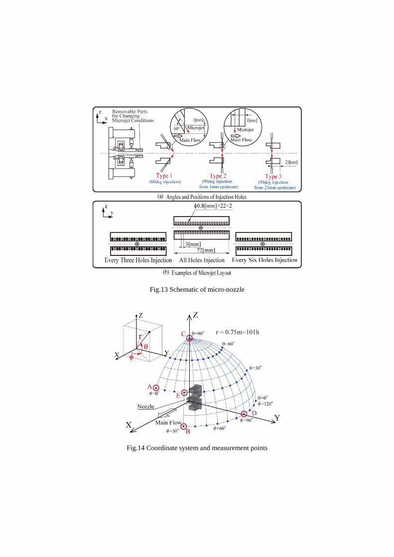
Fig.13 Schematic of micro-nozzle
Fig.14 Coordinate system and measurement points

3.2 Results and Discussions
Figure 15 presents the power spectra of the sound pressure in the case of type
2 every-three-hole injection. In the figure, spectra of the cases with microjet
pressure of Pm=0.51MPa and Pm=0.20MPa, and the case without microjet are
compared. The microphone is located at (, )=(30deg, 0deg), which is right
above the main jet.
In the case without microjet, the spectrum peak of the screech tone noise can
be seen at the frequency of 7.8 kHz. The peak noise at the frequency from 3 kHz
to 5 kHz is composed of the noise from large-scale turbulence and the broadband
shock-associated noise, judging from the literature knowledge (8)
and configura-
tion of the spectrum. In Fig.15, the broadband noise from 1 to 5 kHz is considera-
bly reduced in the case of Pm=0.51MPa. The screech tone noise is also found to
disappear perfectly. In the case of Pm=0.20MPa, however, the reduction of broad-
band noise is less than the case of Pm=0.51MPa and the screech tone noise is not
so much reduced. The mass flux ratio of the microjet to the main jet, , was
1.05% in the case of Pm=0.51MPa, and 0.24% in the case of Pm=0.20MPa.
In the acoustic measurement, the reduction of the OASPL up to approximately
10dB was observed. In this case, the mass flux ratio of the microjet to main jet
was about 1%.
Figure 16 shows the schlieren pictures in the case of M=1.47. The main jet
contains shock wave structure. It is clearly seen that large fluctuations of jet shear
layers in the case without microjet are suppressed by microjet injection. The
large-scale coherent turbulence structures, observed in Fig.16 (a), are also sup-
pressed by microjet. Tam (8)
stated that broadband shock-associated noise and
screech tone noise are generated only when a quasi-periodic shock cell structure
is present in the jet plume. The flow field of the case with microjet loses the peri-
odic shock cell structure. Moreover, the large-scale turbulence structures obvious-
ly disappear, as stated above. Therefore, it can be concluded that the interaction
between the shock cell and the large-scale turbulence structure could be weakened
by microjet and the generation of the shock-associated noise and the screech tone
noise could be reduced.
3.3 Concluding Remarks
The effect of microjet injection on supersonic jet noise was found to be re-
markable. The broadband peak noise and screech tone noise were greatly reduced
using microjet injection. The high frequency turbulent mixing noise was, however,
increased due to microjet injection in the sideline and backward direction of the
main jet. The unsteady flow field visualization showed that microjet suppressed
large fluctuation of jet shear layers, the development of large-scale turbulence
structures and the generation of the screech tone noise.

Fig. 15 Example of Power spectra at =30deg, =0deg
(M=1.47, type 2 every three holes injection)
(a) w/o microjet
(b) type 2 every three holes injection
Fig. 16 Instantaneous schlieren pictures (M=1.47)

4. Conclusions
Two examples of active control on unsteady flow phenomena were reviewed.
Active suppression of cascade flutter with piezoelectric device was examined
by numerical and experimental studies. For transonic compressor cascade in
which the shock behavior governed the vibration instability, the control method of
active oscillation on blade trailing edge was found to effectively suppress the
cascade flutter in the numerical analysis. The potential of the control method was
qualitatively revealed in the trial experiment in a transonic cascade tunnel.
For reduction of supersonic jet noise, the microjet injection technique was ex-
perimentally investigated in an anechoic chamber. The noise level was effectively
reduced up to 10 dB in a point-wise SPL. The flow visualization showed that the
unstable motion of supersonic jet with shock structure was dramatically sup-
pressed. The suppression effect probably alleviated the generation of screech tone
noise and shock-associated noise.
Though there would be many steps to install these active control methods into
aeroengines, the results would provide useful tools for environmentally friendly,
ultra-highly efficient engines in the near future.
References
(1) Kazawa, J. and Watanabe, T., “Active Suppression of Cascade Flutter with
Piezoelectric Device”, ASME GT2006-90645, Proceedings of ASME Turbo Expo
2006, Barcelona, 2006.
(2) e.g. Vijaya, M. S., “Piezoelectric Materials and Devices”, CRC Press, 2012.
(3) Watanabe, T., Kazawa, J., Uzawa, S., and Keim, B., “Numerical and Experi-
mental Study of Active Flutter Suppression with Piezoelectric Device for Tran-
sonic Cascade”, ASME GT2008-51467, Proceedings of ASME Turbo Expo 2008,
Berlin, 2008.
(4) Okada, R., Watanabe, T., Uzawa, S., Himeno, T., and Oishi, T., “Investigation
of Microjet Injection for Reduction of Supersonic Jet Noise”, ASME GT 2010-
23036, Proceedings of ASME Turbo Expo 2010, Glasgow, 2010.
(5) Okada, R., Watanabe, T., Uzawa, S., Himeno, T., and Oishi, T., “ Influence of
Microjet Condition on Characteristics of Supersonic Jet Noise and Flow Field,
ASME GT 2012-68821, Proceedings of ASME Turbo Expo 2012, Copenhagen,
2012.
(6) NASA “Experimental Quiet Engine Program,” contract No.NAS3-12430,
March 1970.
(7) Shibata, T., and Kaji, S., “Role of Shock Structures in Transonic Fan Rotor
Flutter,” Unsteady Aerodynamics and Aeroelasticity of Turbomachines, Fransson,
T. H. ed., Kluwer Academic Publishers, 1998, pp.733-747.
(8) Tam, C. K. W. “Supersonic Jet Noise”, Journal of Fluid Mechanics, vol.27,
1995, pp17-43.