Embed Size (px)
Citation preview
Review of Basic Electrical and Magnetic Circuit Concepts
EE 442-642
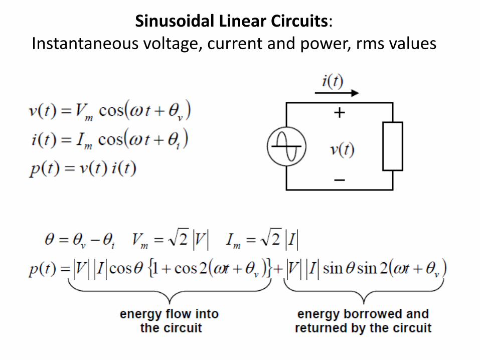
Sinusoidal Linear Circuits: Instantaneous voltage, current and power, rms values
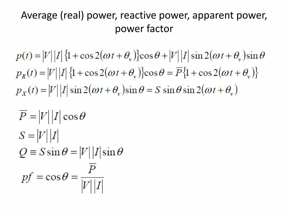
Average (real) power, reactive power, apparent power, power factor
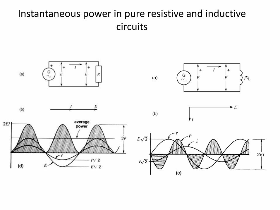
Instantaneous power in pure resistive and inductive circuits
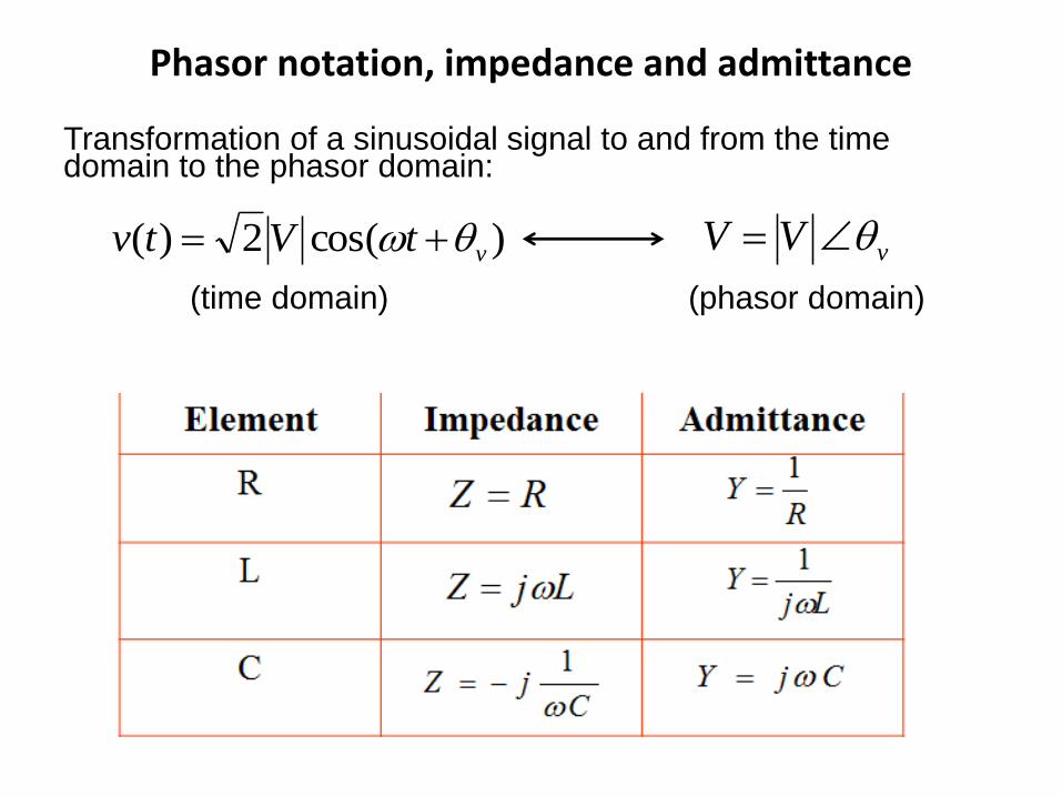
Phasor notation, impedance and admittance
Transformation of a sinusoidal signal to and from the time domain to the phasor domain:
(time domain) (phasor domain)
)cos(2)( vtVtv vVV
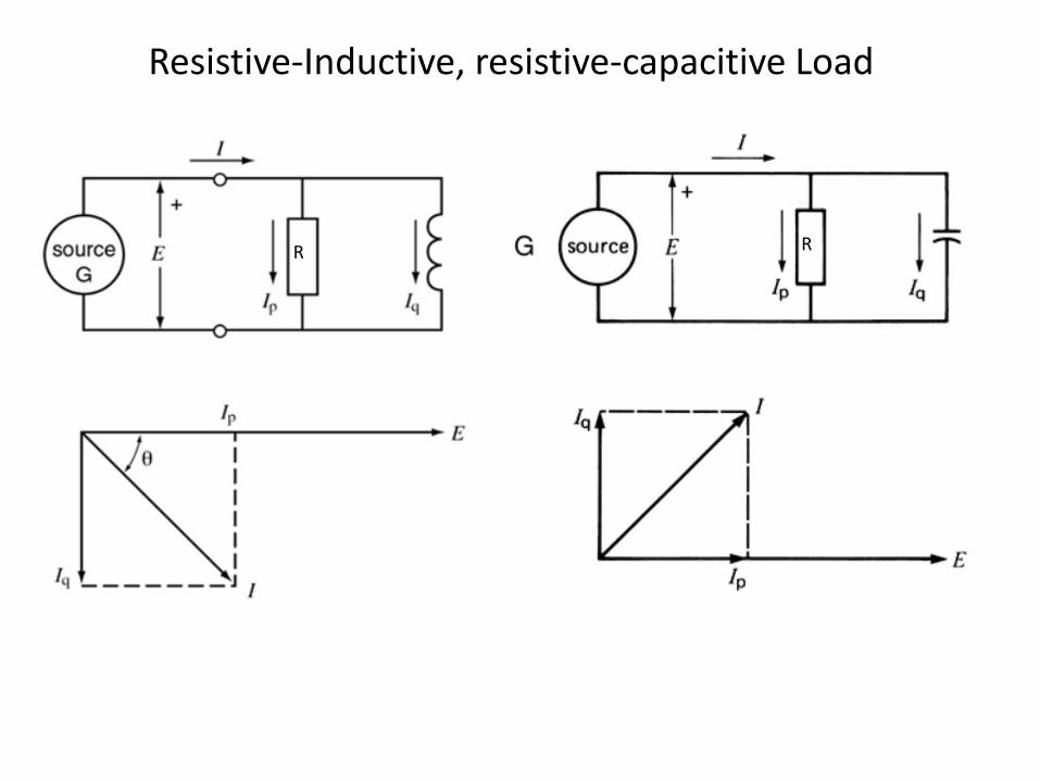
Resistive-Inductive, resistive-capacitive Load
R R
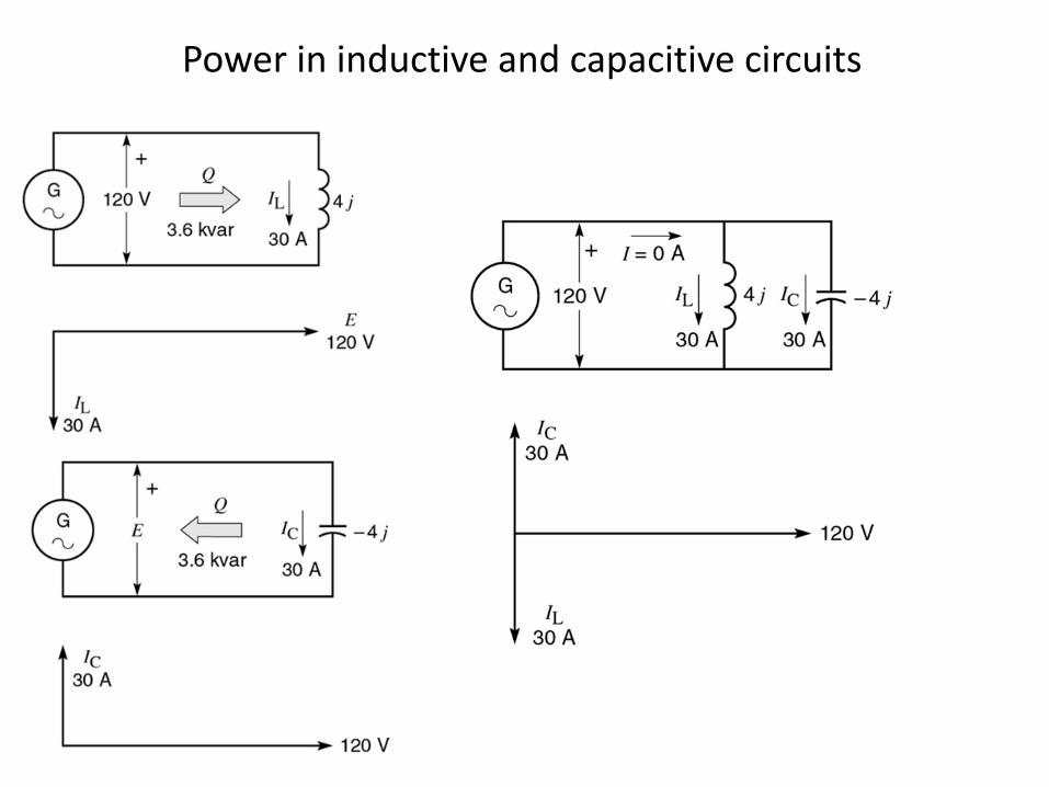
Power in inductive and capacitive circuits
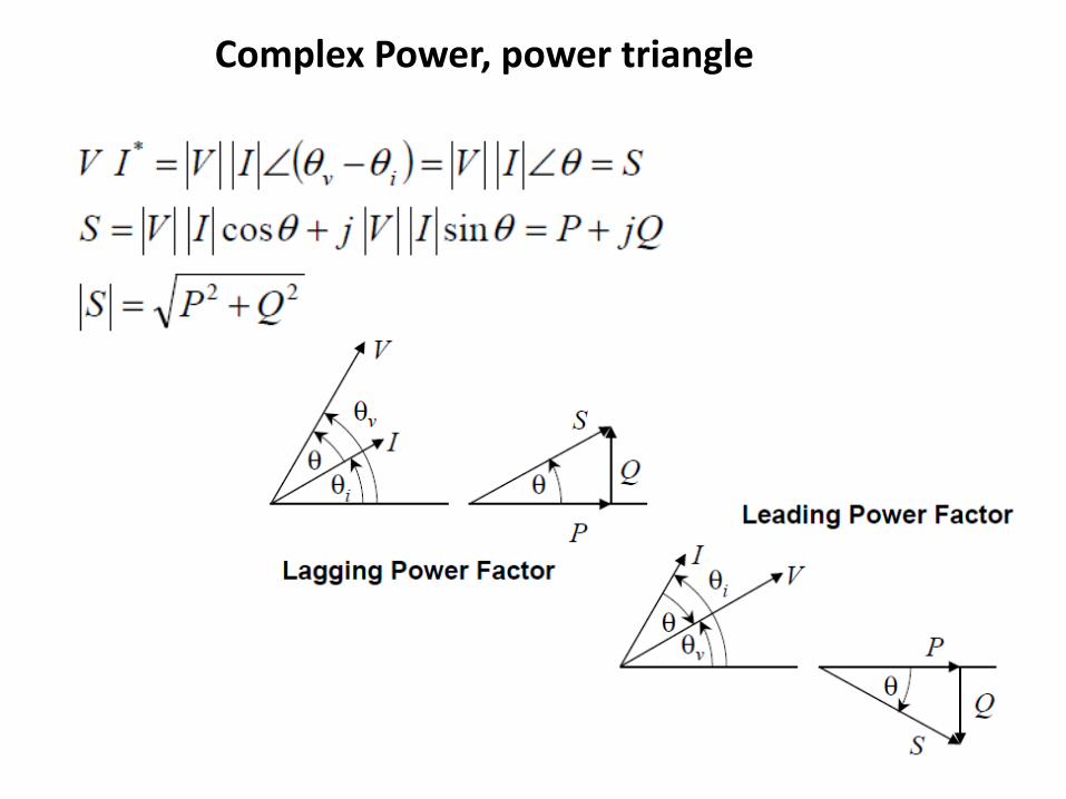
Complex Power, power triangle
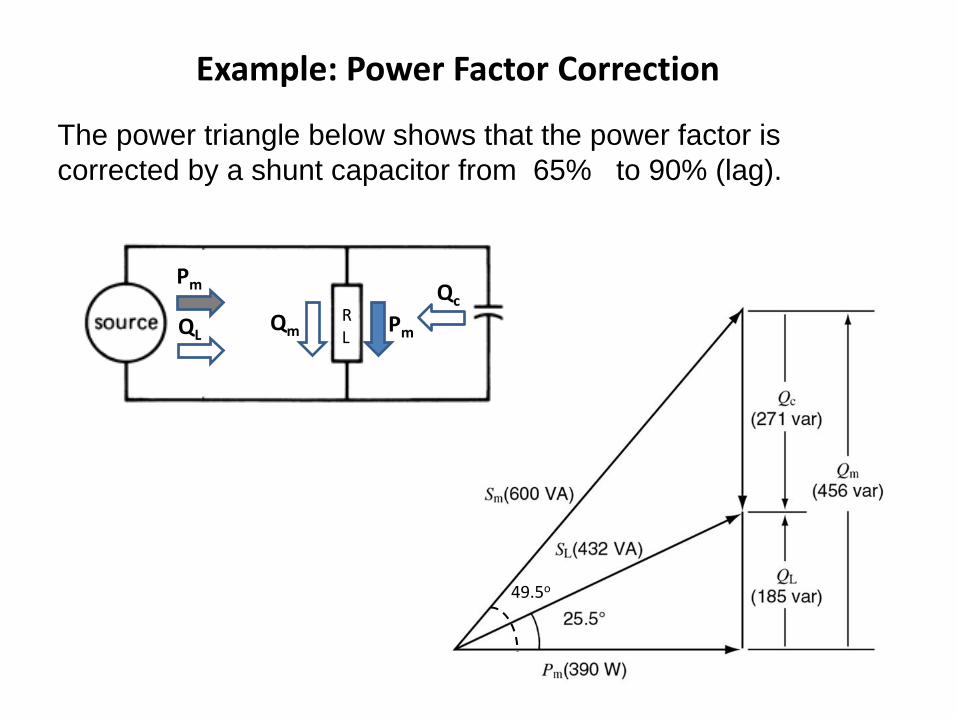
Example: Power Factor Correction
The power triangle below shows that the power factor is
corrected by a shunt capacitor from 65% to 90% (lag).
49.5o
R L
Ic
IL
Qc
Qm QL Pm
Pm
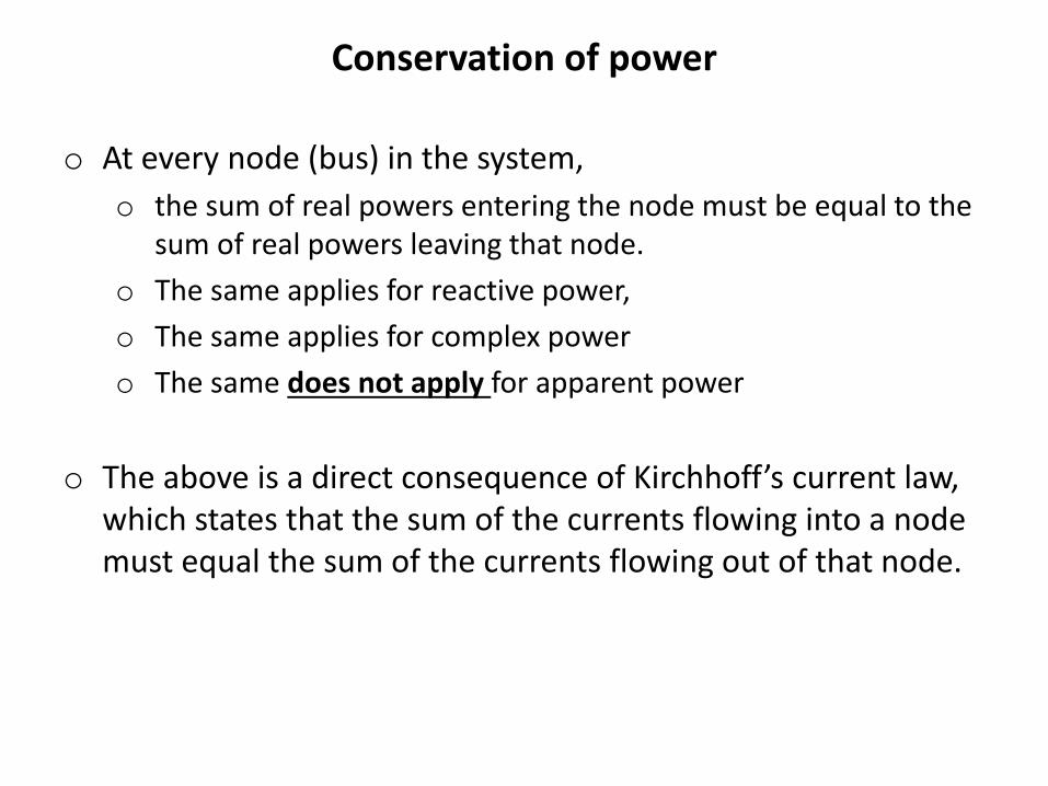
Conservation of power
o At every node (bus) in the system,
o the sum of real powers entering the node must be equal to the sum of real powers leaving that node.
o The same applies for reactive power,
o The same applies for complex power
o The same does not apply for apparent power
o The above is a direct consequence of Kirchhoff’s current law, which states that the sum of the currents flowing into a node must equal the sum of the currents flowing out of that node.
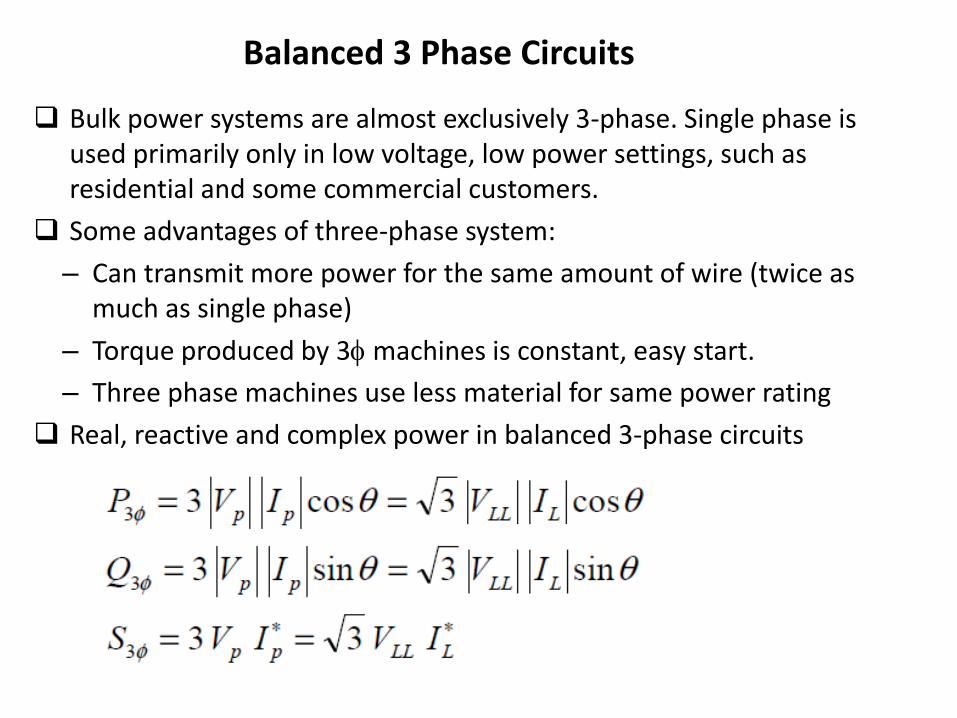
Balanced 3 Phase Circuits
Bulk power systems are almost exclusively 3-phase. Single phase is used primarily only in low voltage, low power settings, such as residential and some commercial customers.
Some advantages of three-phase system:
– Can transmit more power for the same amount of wire (twice as much as single phase)
– Torque produced by 3 machines is constant, easy start.
– Three phase machines use less material for same power rating
Real, reactive and complex power in balanced 3-phase circuits
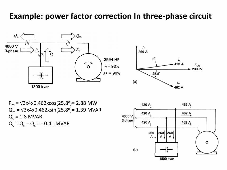
Example: power factor correction In three-phase circuit
PF
Pm = √3x4x0.462xcos(25.8o)= 2.88 MW Qm = √3x4x0.462xsin(25.8o)= 1.39 MVAR Qc = 1.8 MVAR QL = Qm - Qc = - 0.41 MVAR
m m
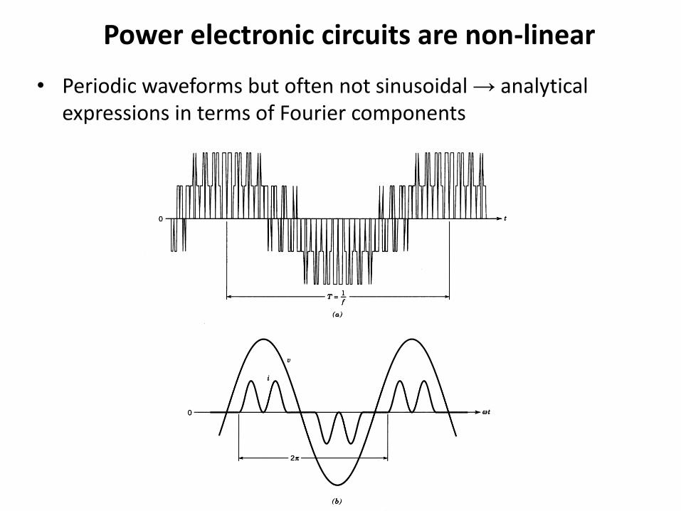
Power electronic circuits are non-linear
• Periodic waveforms but often not sinusoidal → analytical expressions in terms of Fourier components
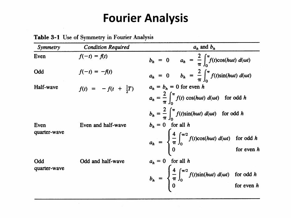
Fourier Analysis

Example of simple non-sinusoidal periodic signals
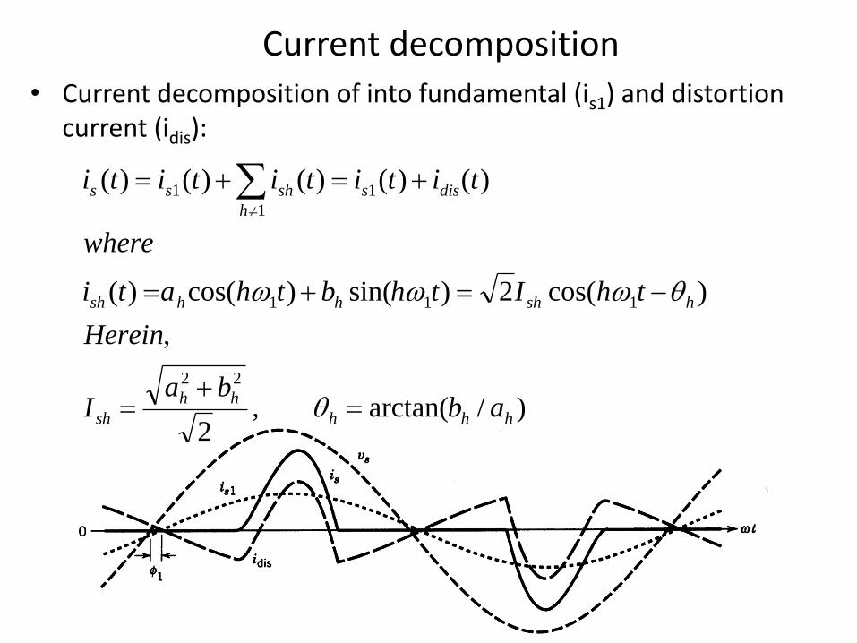
Current decomposition • Current decomposition of into fundamental (is1) and distortion
current (idis):
)/arctan(,2
,
)cos(2)sin()cos()(
)()()()()(
22
111
1
1
1
hhh
hh
sh
hshhhsh
diss
h
shss
abba
I
Herein
thIthbthati
where
tititititi
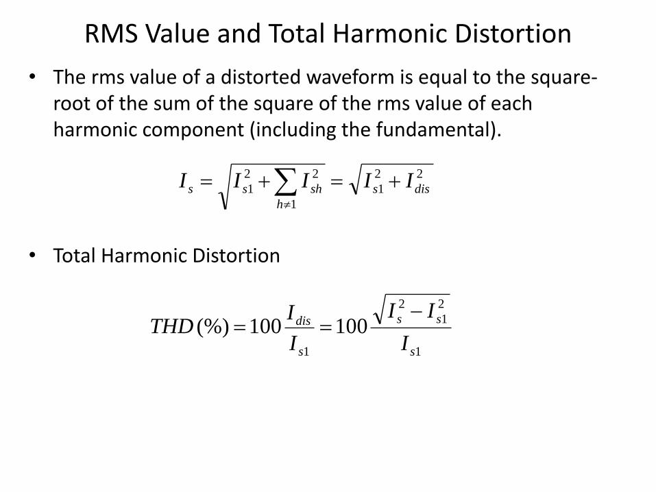
RMS Value and Total Harmonic Distortion
• The rms value of a distorted waveform is equal to the square-root of the sum of the square of the rms value of each harmonic component (including the fundamental).
• Total Harmonic Distortion
22
1
1
22
1 diss
h
shss IIIII
1
2
1
2
1
100100(%)s
ss
s
dis
I
II
I
ITHD
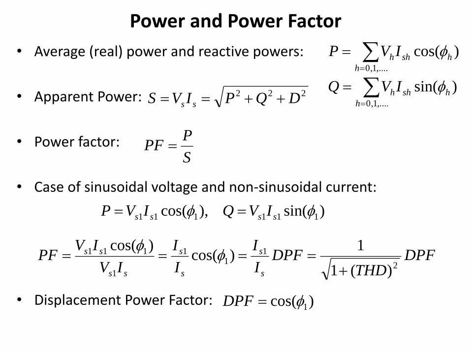
Power and Power Factor
• Average (real) power and reactive powers:
• Apparent Power:
• Power factor:
• Case of sinusoidal voltage and non-sinusoidal current:
• Displacement Power Factor:
)cos(,....1,0
hsh
h
hIVP
)sin(),cos( 111111 ssss IVQIVP
222 DQPIVS ss
S
PPF
DPFTHD
DPFI
I
I
I
IV
IVPF
s
s
s
s
ss
ss
2
11
1
1
111
)(1
1)cos(
)cos(
)cos( 1DPF
)sin(,....1,0
hsh
h
hIVQ
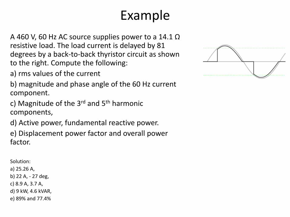
Example
A 460 V, 60 Hz AC source supplies power to a 14.1 Ω resistive load. The load current is delayed by 81 degrees by a back-to-back thyristor circuit as shown to the right. Compute the following:
a) rms values of the current
b) magnitude and phase angle of the 60 Hz current component.
c) Magnitude of the 3rd and 5th harmonic components,
d) Active power, fundamental reactive power.
e) Displacement power factor and overall power factor.
Solution:
a) 25.26 A,
b) 22 A, - 27 deg,
c) 8.9 A, 3.7 A,
d) 9 kW, 4.6 kVAR,
e) 89% and 77.4%
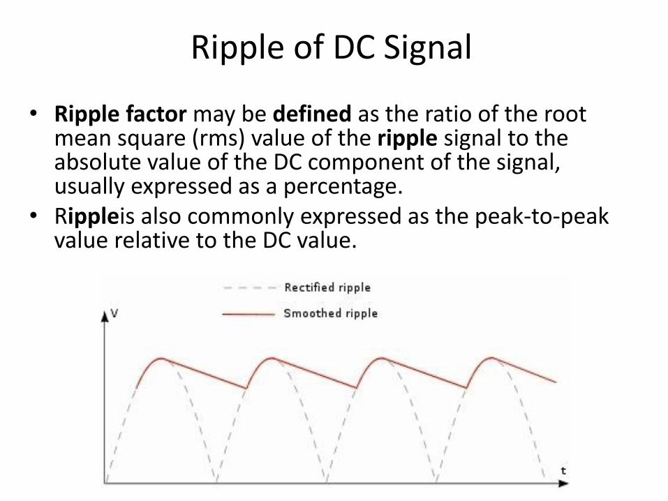
Ripple of DC Signal
• Ripple factor may be defined as the ratio of the root mean square (rms) value of the ripple signal to the absolute value of the DC component of the signal, usually expressed as a percentage.
• Rippleis also commonly expressed as the peak-to-peak value relative to the DC value.
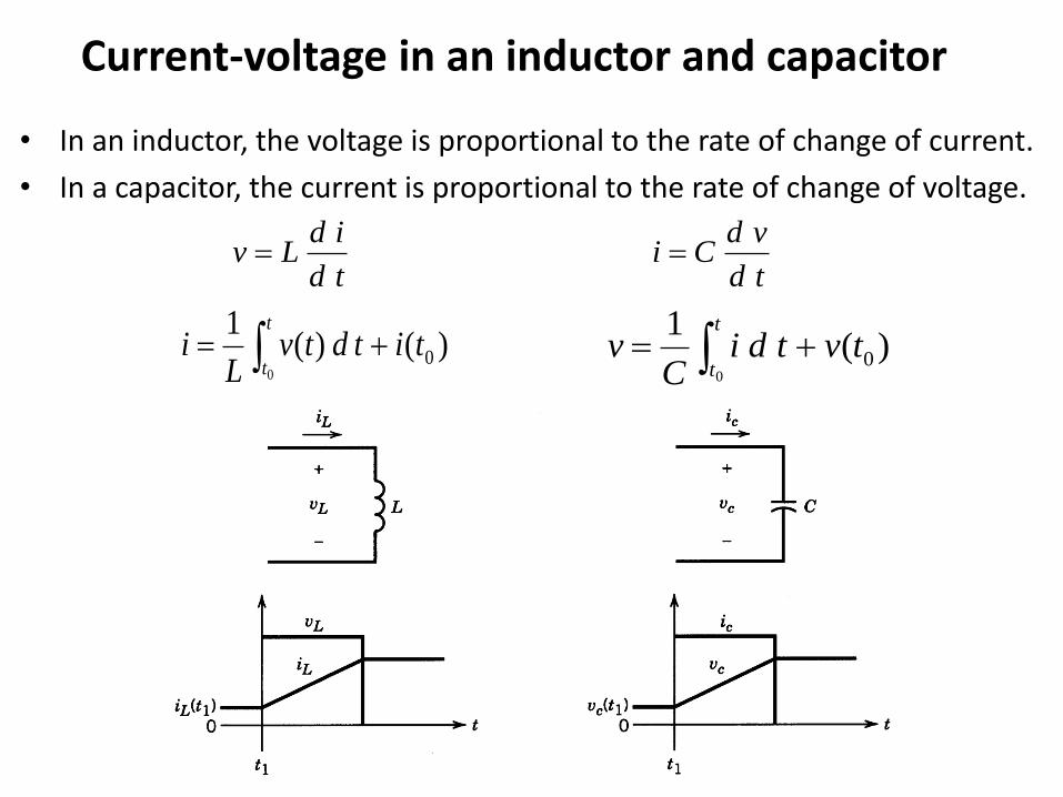
Current-voltage in an inductor and capacitor
• In an inductor, the voltage is proportional to the rate of change of current.
• In a capacitor, the current is proportional to the rate of change of voltage.
td
vdCi
td
idLv
)()(1
00
titdtvL
it
t )(
10
0
tvtdiC
vt
t
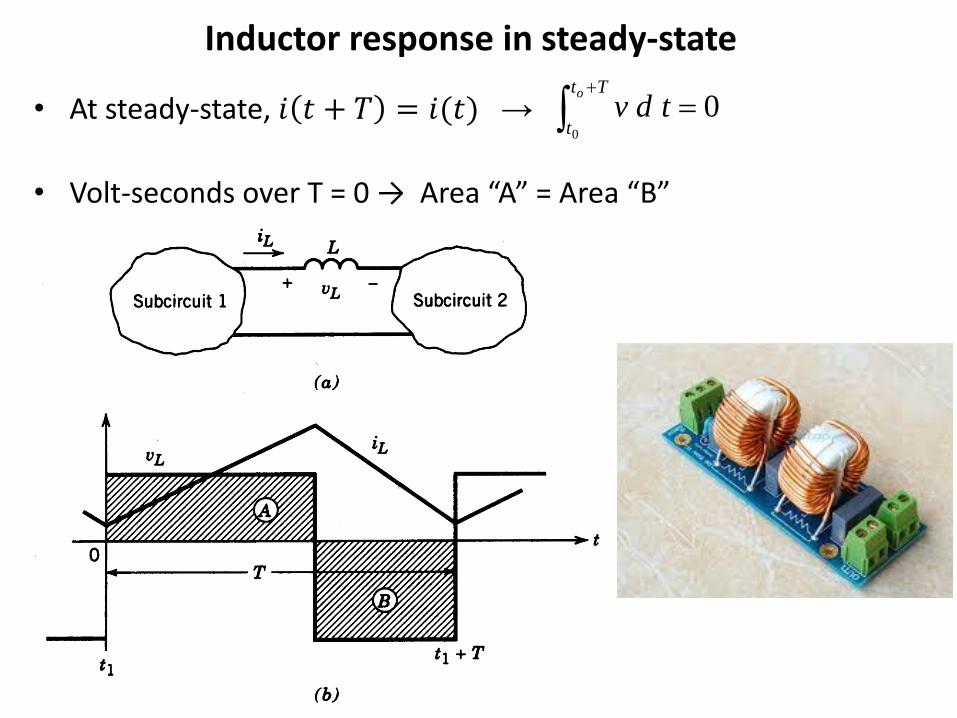
Inductor response in steady-state
• At steady-state, 𝑖 𝑡 + 𝑇 = 𝑖(𝑡) →
• Volt-seconds over T = 0 → Area “A” = Area “B”
00
Tt
t
o
tdv
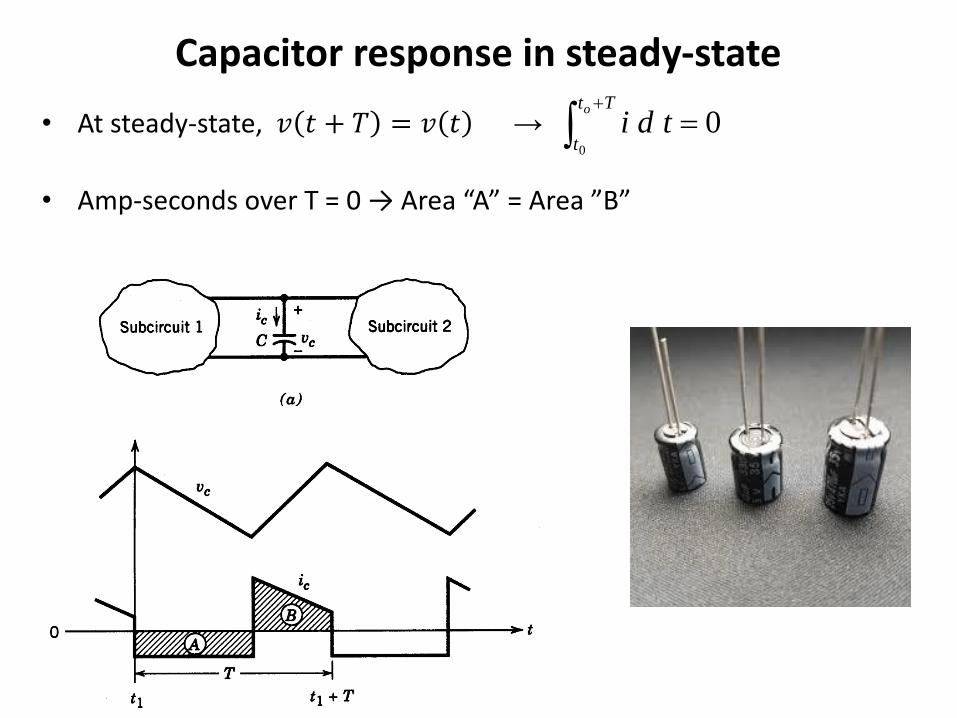
Capacitor response in steady-state
• At steady-state, 𝑣 𝑡 + 𝑇 = 𝑣 𝑡 →
• Amp-seconds over T = 0 → Area “A” = Area ”B”
00
Tt
t
o
tdi
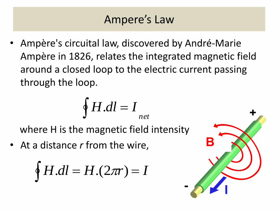
Ampere’s Law
• Ampère's circuital law, discovered by André-Marie Ampère in 1826, relates the integrated magnetic field around a closed loop to the electric current passing through the loop.
where H is the magnetic field intensity
• At a distance r from the wire,
netIdlH .
IrHdlH )2.(.
Magnetic Flux Density
• Relation between magnetic field intensity H and magnetic field density B:
where
– μr is the relative permeability of the medium (unit-less),
– μo is the permeability of free space (= 4πx10-7 H/m)
HHB r )( 0
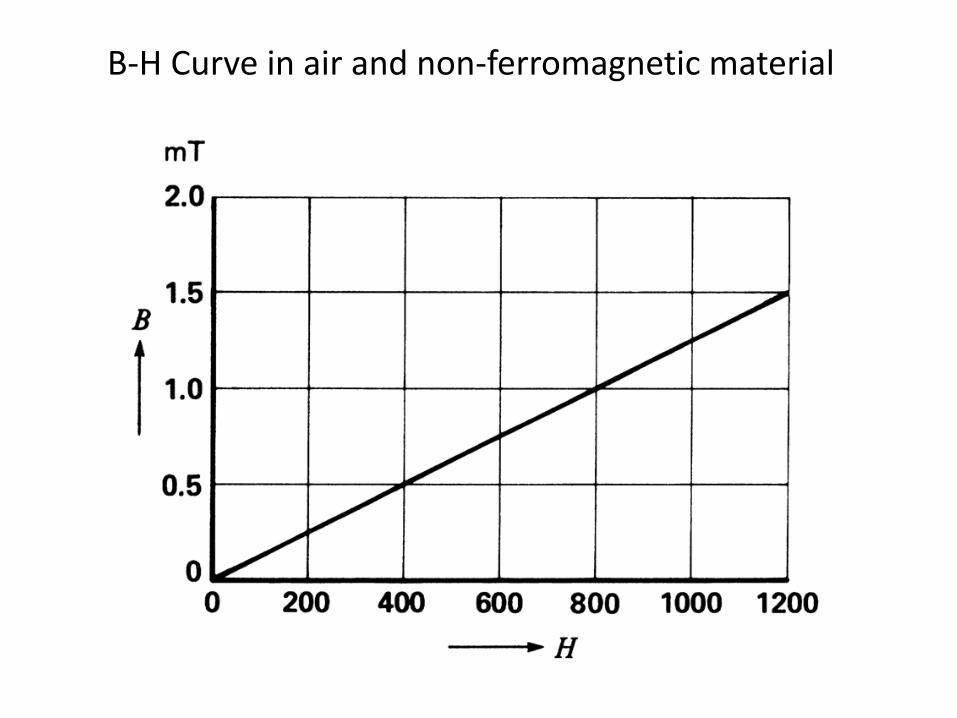
B-H Curve in air and non-ferromagnetic material
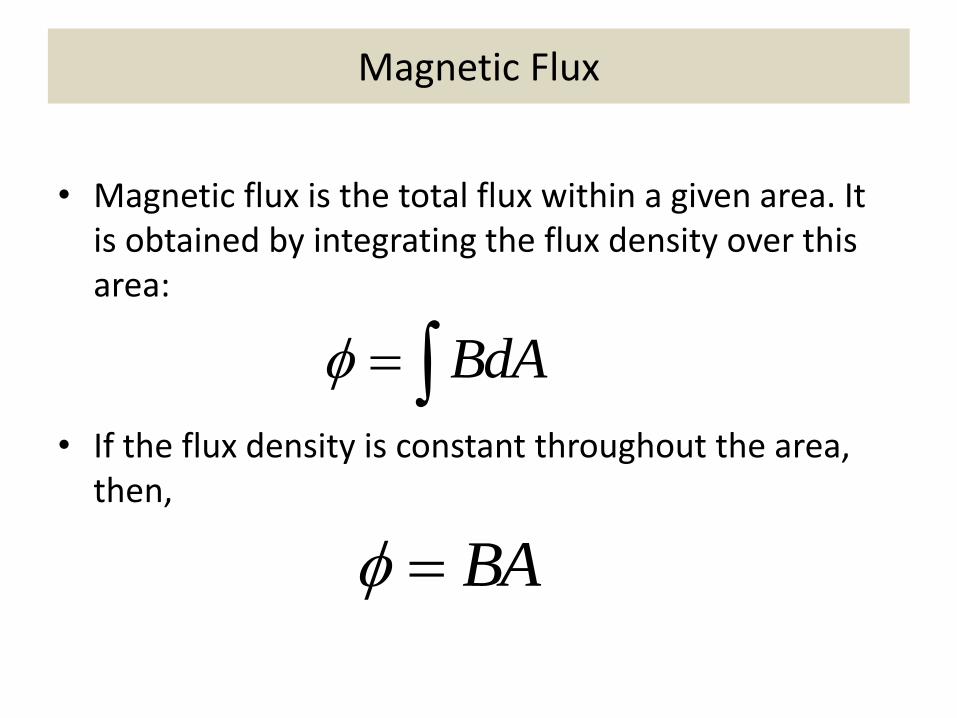
Magnetic Flux
• Magnetic flux is the total flux within a given area. It is obtained by integrating the flux density over this area:
• If the flux density is constant throughout the area, then,
BdA
BA
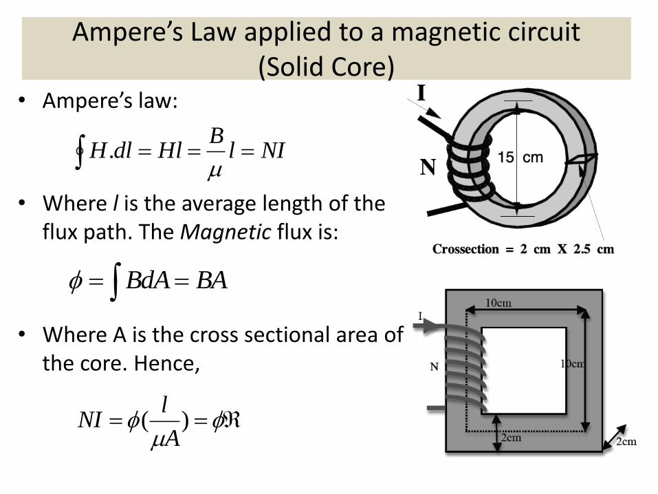
Ampere’s Law applied to a magnetic circuit (Solid Core)
• Ampere’s law:
• Where l is the average length of the flux path. The Magnetic flux is:
• Where A is the cross sectional area of the core. Hence,
NIlB
HldlH
.
BAdAB
)(A
lNI
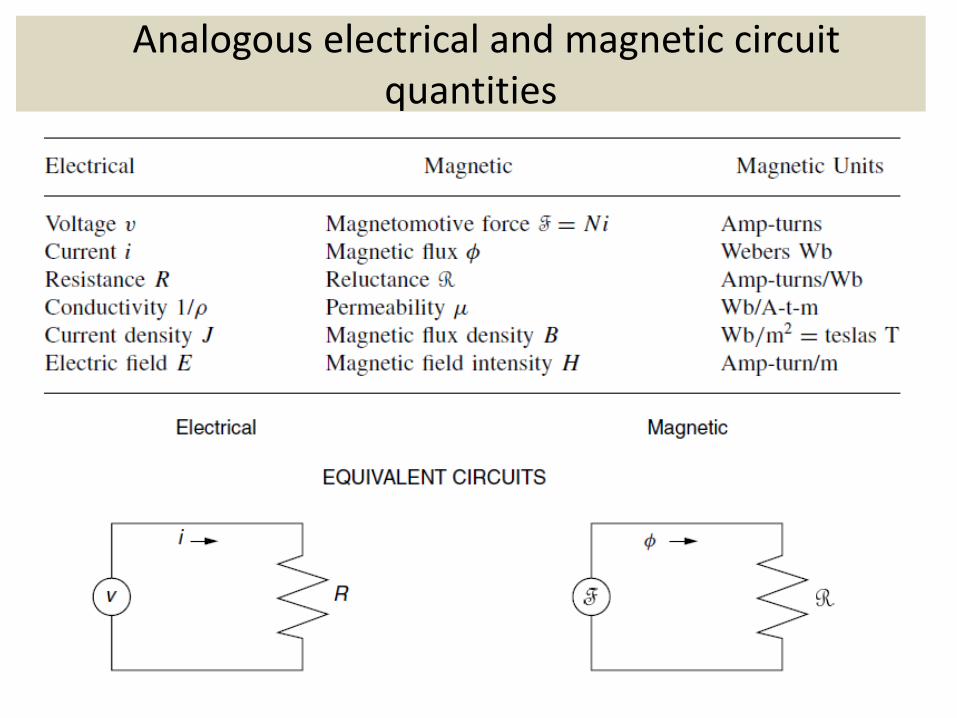
Analogous electrical and magnetic circuit quantities
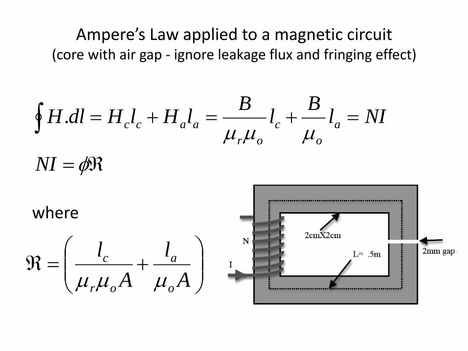
Ampere’s Law applied to a magnetic circuit (core with air gap - ignore leakage flux and fringing effect)
NI
NIlB
lB
lHlHdlH a
o
c
or
aacc.
A
l
A
l
o
a
or
c
where

B-H Curve of Ferromagnetic materials
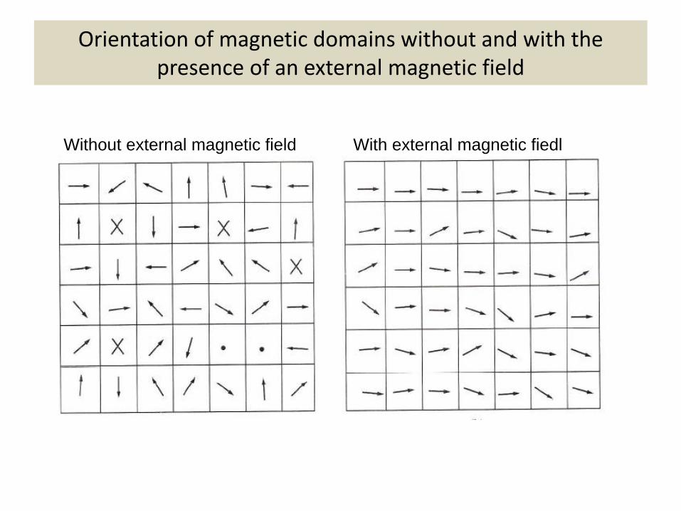
Orientation of magnetic domains without and with the presence of an external magnetic field
Without external magnetic field With external magnetic fiedl
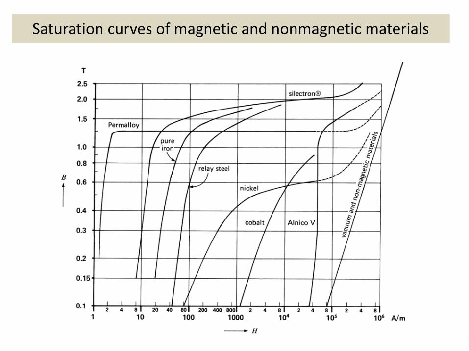
Saturation curves of magnetic and nonmagnetic materials
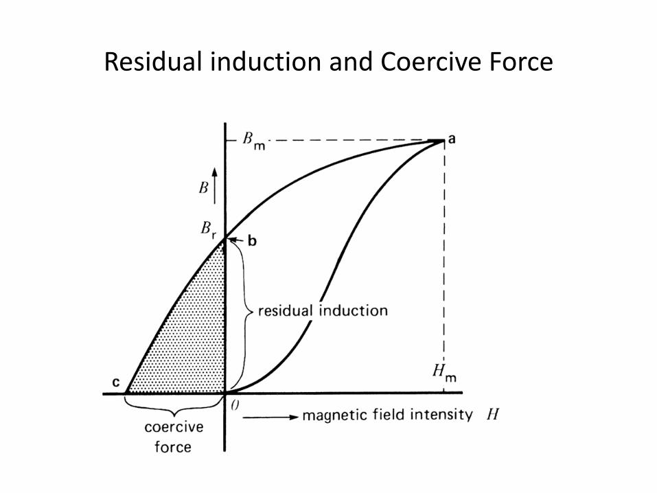
Residual induction and Coercive Force

Hysteresis Loop traced by the flux in a core under AC current
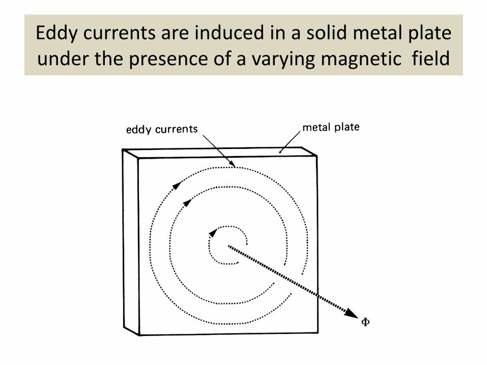
Eddy currents are induced in a solid metal plate under the presence of a varying magnetic field
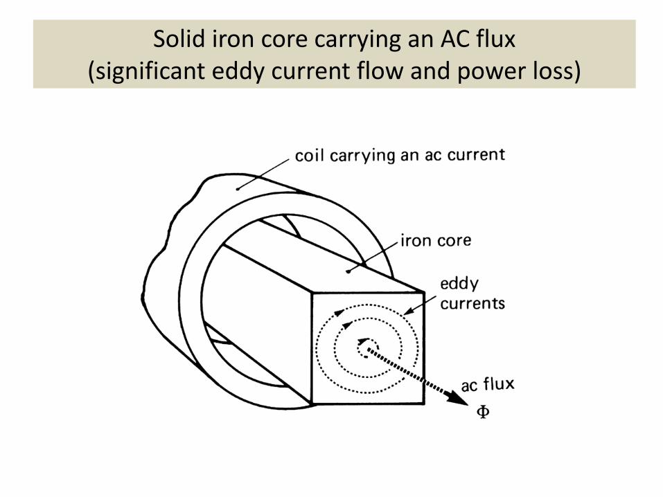
Solid iron core carrying an AC flux (significant eddy current flow and power loss)
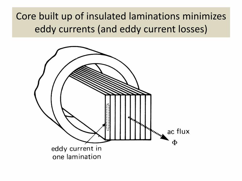
Core built up of insulated laminations minimizes eddy currents (and eddy current losses)
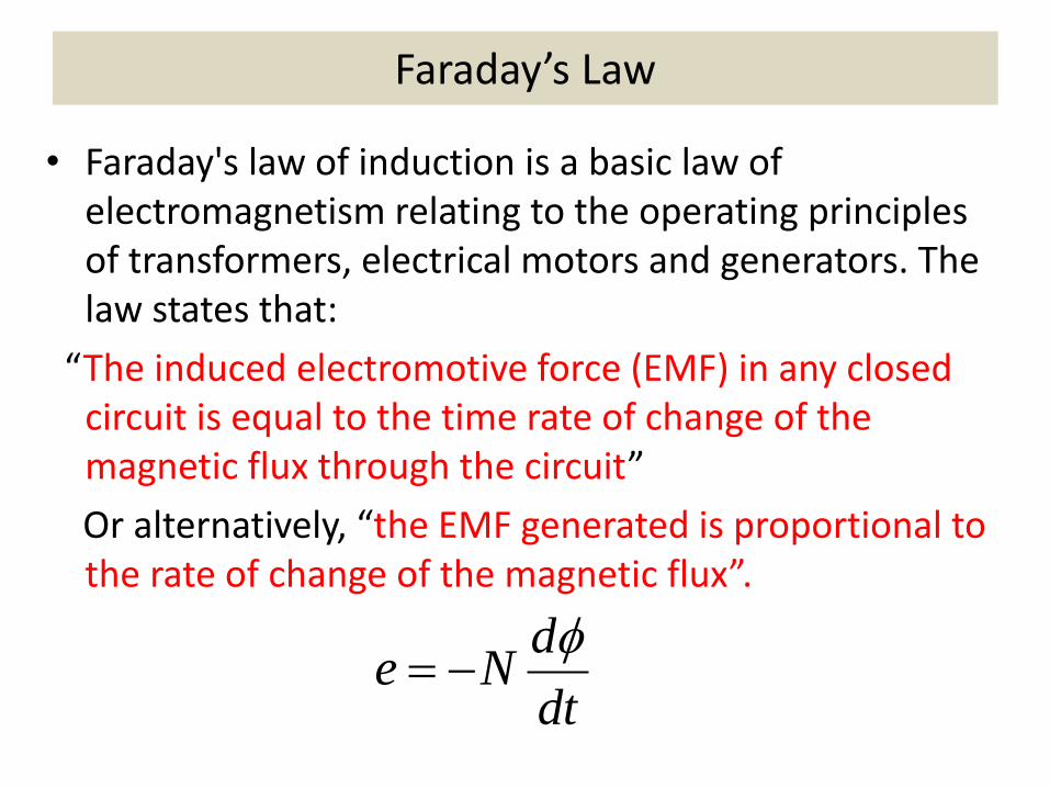
Faraday’s Law
• Faraday's law of induction is a basic law of electromagnetism relating to the operating principles of transformers, electrical motors and generators. The law states that:
“The induced electromotive force (EMF) in any closed circuit is equal to the time rate of change of the magnetic flux through the circuit”
Or alternatively, “the EMF generated is proportional to the rate of change of the magnetic flux”.
dt
dNe
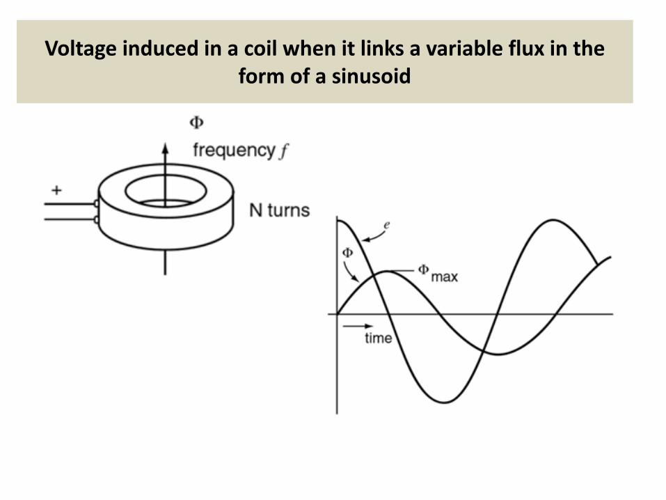
Voltage induced in a coil when it links a variable flux in the form of a sinusoid
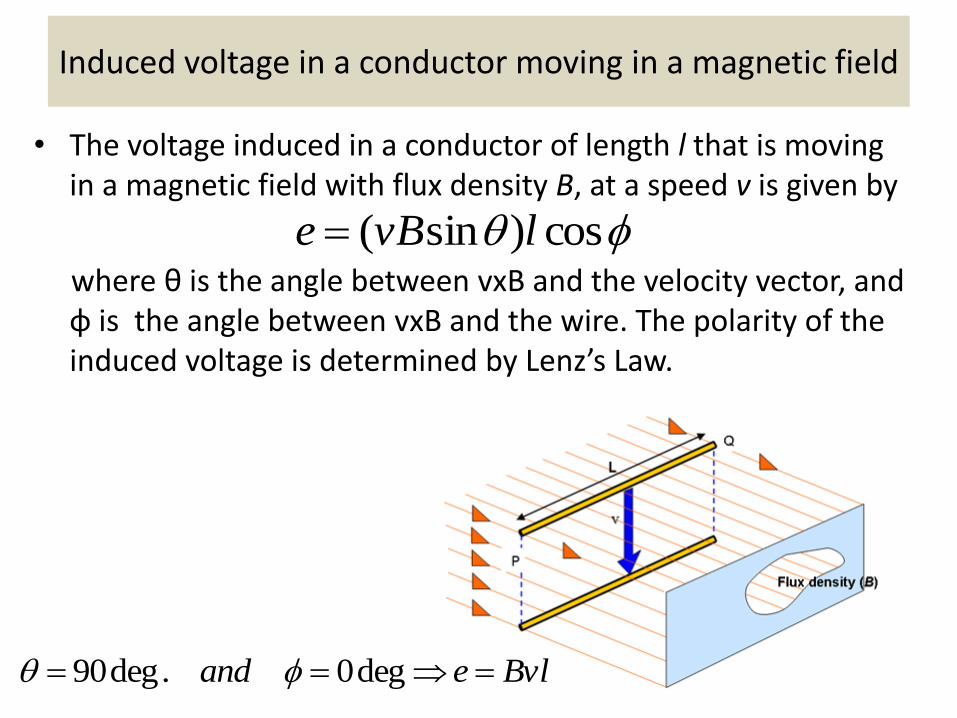
Induced voltage in a conductor moving in a magnetic field
• The voltage induced in a conductor of length l that is moving in a magnetic field with flux density B, at a speed v is given by
where θ is the angle between vxB and the velocity vector, and φ is the angle between vxB and the wire. The polarity of the induced voltage is determined by Lenz’s Law.
cos)sin( lvBe
Bvleand deg0.deg90
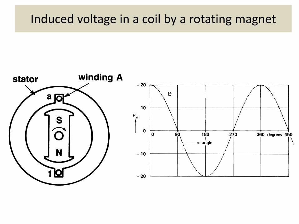
Induced voltage in a coil by a rotating magnet
e
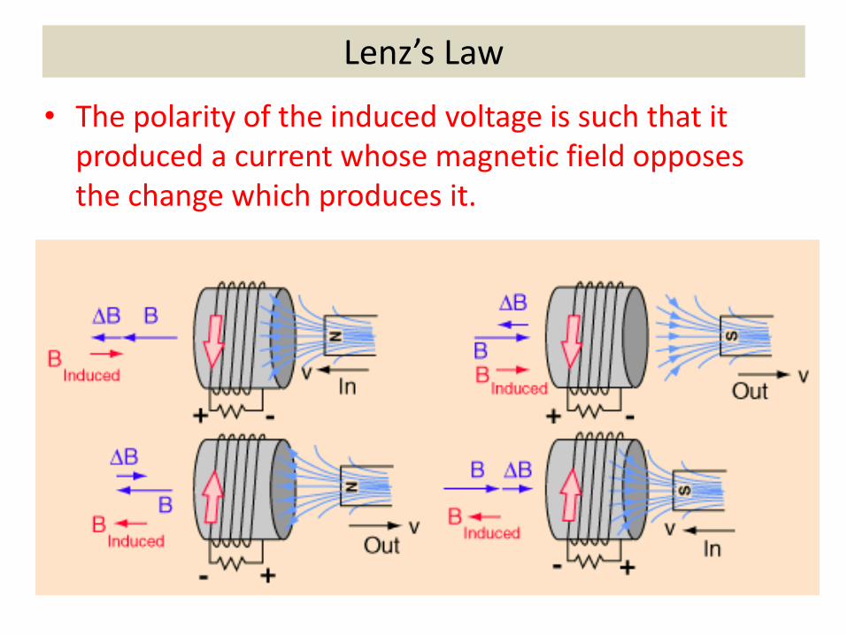
Lenz’s Law
• The polarity of the induced voltage is such that it produced a current whose magnetic field opposes the change which produces it.
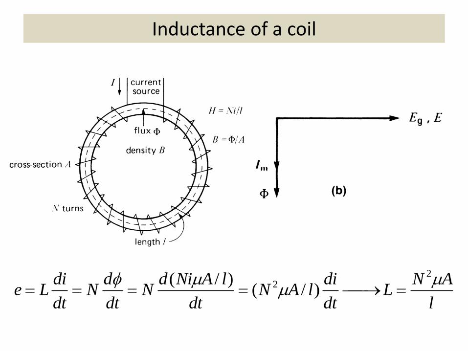
Inductance of a coil
l
ANL
dt
dilAN
dt
lANidN
dt
dN
dt
diLe
22 )/(
)/(
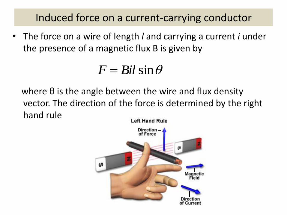
Induced force on a current-carrying conductor
• The force on a wire of length l and carrying a current i under the presence of a magnetic flux B is given by
where θ is the angle between the wire and flux density vector. The direction of the force is determined by the right hand rule
sinBilF
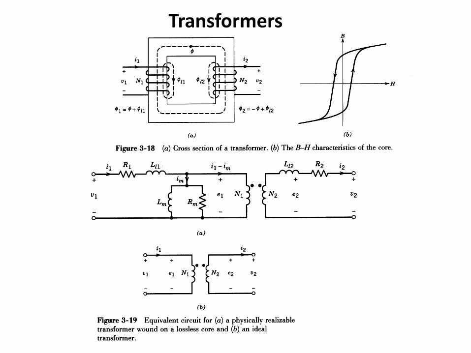
Transformers
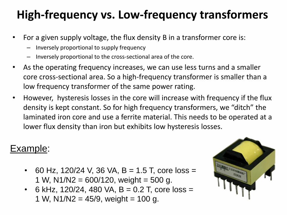
High-frequency vs. Low-frequency transformers
• For a given supply voltage, the flux density B in a transformer core is: – Inversely proportional to supply frequency
– Inversely proportional to the cross-sectional area of the core.
• As the operating frequency increases, we can use less turns and a smaller core cross-sectional area. So a high-frequency transformer is smaller than a low frequency transformer of the same power rating.
• However, hysteresis losses in the core will increase with frequency if the flux density is kept constant. So for high frequency transformers, we “ditch” the laminated iron core and use a ferrite material. This needs to be operated at a lower flux density than iron but exhibits low hysteresis losses.
Example:
• 60 Hz, 120/24 V, 36 VA, B = 1.5 T, core loss =
1 W, N1/N2 = 600/120, weight = 500 g.
• 6 kHz, 120/24, 480 VA, B = 0.2 T, core loss =
1 W, N1/N2 = 45/9, weight = 100 g.

![Performance and Stability Limitations of Admittance-Based ......electromechanical haptic interface dynamics, a coupled human impedance model [17], and the rendered virtual admittance](https://img.pdfslide.net/doc/110x75/60e2c1820229ae2f2a082f23/performance-and-stability-limitations-of-admittance-based-electromechanical.jpg)