Embed Size (px)
Citation preview
Review of High Power Ultrasound – Industrial Applications and Measurement Methods
G. Harvey1, A. Gachagan2, T. Mutasa2
1 Weidlinger Associates Ltd, Glasgow , Scotland, G1 1XP.
2 Centre for Ultrasonic Engineering, Dept of EEE, 204 George St, Glasgow, Scotland, G1 1XW.
Abstract
Applications involving high power ultrasound are expanding rapidly as ultrasonic intensification
opportunities are identified in new fields. This is facilitated through new technological
developments and an evolution of current systems to tackle challenging problems. It is therefore
important to continually update both the scientific and commercial communities on the current
system performance and limitations. In order to achieve this aim, this paper addresses two key
aspects of high power ultrasonic systems. In the first part, the review of high power application
focusses on industrial applications and documents the developing technology from its early
cleaning applications through to the advanced sonochemistry, cutting and water treatment
applications used today. The second part provides a comprehensive overview of measurement
techniques used in conjunction with high power ultrasonic systems. This is an important and
evolving field which enables design and process engineers to optimise the behaviour and/or
operation of key metrics of system performance, such as field distribution or cavitation intensity.
1. Introduction
Since the pioneering work published by Lord Rayleigh on the theory of sound in 1896 [1],
ultrasound has been utilised in a wide variety of applications. The prolificacy of ultrasound in fields
such as SONAR [2], Non-Destructive Testing (NDT) [3] and biomedical imaging [4] has produced
an abundance of literature since the beginning of the First World War, where its potential as a viable
means to detect submerged objects became apparent. The innovative work conducted during
wartime by scientists such as Langevin, continued unabated in post war years with attention turning
away from large scale inspection of the oceans to small scale probing of specific regions of interest.
The concept of ultrasonic metal flaw detection was first suggested by Sokolov in 1928 although the
absence of suitable equipment to generate and receive short pulses until the early 1940’s resulted in
very poor resolution. By 1948 researchers in the United States and Japan were independently
investigating the potential of ultrasound as a medical diagnostic tool. Previously, the use of
ultrasound in medicine had initially begun with rudimentary applications in therapy, e.g. tissue
breakdown, rather than imaging. This destructive ability of high intensity ultrasound was observed
by Langevin when he noted the death of schools of fish in the sea and pain induced in the hand
when placed in a water tank insonated with high intensity ultrasound. It was around this time that
development work into the use of high intensity ultrasound for industrial processes began.
In this paper, the definition of ‘high power’ or ‘high intensity’ is considered as the establishment of
an ultrasonic field that directly influences a process, i.e. to induce a physical change in a target
object or region through exposure to vibrational energy. Quite often, this involves the utilisation of
cavitation, discussed in Section 2, to produce some desired effect. In addition, the ultrasonic
frequency of operation has a direct impact on the characteristics and acoustic performance of a high
intensity field. In this review, we consider high power applications operate using low frequencies
(10 kHz to 500 kHz), as this is more conducive to efficient generation of cavitation. There are, of
course, exceptions to this categorisation, such as SONAR, where intense power levels are involved
in conveying information, proximity sensing using low frequency ‘air-coupled’ transducers and
High Intensity Focussed Ultrasound (HIFU) applications, where high frequency fields are used to
destroy tissue.
Measurement methods for these high power fields are important for safety and process efficiency
reasons yet, currently, there are very few well-documented and reliable measurement methods
available. Initially, due to the harmful tissue damaging effects experienced in the early use of
ultrasound in medicine, the development of standard measurement techniques required to quantify
medical equipment output levels was quick and comprehensive [5, 6]. Moreover, measurement of
the output levels from medical devices is made easier by the fact that many systems operate in
pulsed or tone burst modes, providing the valid assumption that free-field conditions exist. This is
generally not the case for high power systems, with the exception of lithotripsy, which normally
operate in continuous wave (CW) mode and within environments that are extremely reverberant.
This paper will review some of the more common applications of power ultrasonics; provide an
introduction to other high intensity applications such as sonochemistry; and discuss the merits of
current field measurement techniques for application in this interesting field.
2. Applications
A. Overview of Cavitation
For those unfamiliar with cavitation, its generation and mechanisms, a quick review is provided.
For a more extensive analysis of cavitation; the causes, effects and applications, the reader is
referred to Leighton’s impressive text [7]. A very useful tutorial on cavitation by Apfel is also
recommended [8].
Acoustic cavitation is basically acoustically induced bubble activity. The activity of the bubble itself
is not the source of many of the advantageous effects (or disadvantageous effects, depending on the
application) of cavitation; bubble activity can be merely the oscillation in radius size caused by an
incident sound wave. It is the subsequent collapse of these bubbles into a volume considerably less
than their original size that generates the dramatic effects associated with acoustic cavitation.
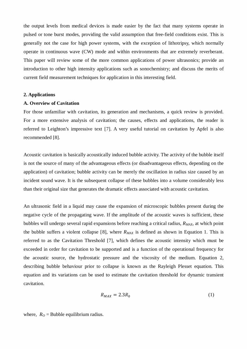
An ultrasonic field in a liquid may cause the expansion of microscopic bubbles present during the
negative cycle of the propagating wave. If the amplitude of the acoustic waves is sufficient, these
bubbles will undergo several rapid expansions before reaching a critical radius, RMAX, at which point
the bubble suffers a violent collapse [8], where RMAX is defined as shown in Equation 1. This is
referred to as the Cavitation Threshold [7], which defines the acoustic intensity which must be
exceeded in order for cavitation to be supported and is a function of the operational frequency for
the acoustic source, the hydrostatic pressure and the viscosity of the medium. Equation 2,
describing bubble behaviour prior to collapse is known as the Rayleigh Plesset equation. This
equation and its variations can be used to estimate the cavitation threshold for dynamic transient
cavitation.
𝑅𝑀𝑀𝑀 = 2.3𝑅0 (1)
where, RO = Bubble equilibrium radius.
𝑅�̈� +
3�̇�2
2 =1𝜌��𝑝0 + +
2𝜎𝑅0
− 𝑝𝑣� �𝑅0𝑅 �
3𝜅
+ 𝑝𝑣 −2𝜎𝑅 −
4𝜂�̇�𝑅 − 𝑝0 − 𝑃(𝑡)�
(2)
Where, R = instantaneous bubble radius, P(t) = dynamic pressure, σ = surface tension, ρ = medium
density, pv = vapour pressure, p0 = hydrostatic pressure, κ = polytropic index and η = sheer
viscosity
Within the region of collapse, several spectacular effects are likely to occur, including an internal
bubble temperature of 3000oK and pressure shockwave emission reaching 6 GPa [9]. Bubble
motion of this nature is called transient cavitation or, more recently, inertial cavitation and the entire
cycle can occur to the seed bubble several times before it fragments. When the amplitude of the
acoustic wave is below the threshold to induce inertial cavitation, the alternative motion of the
bubble is referred to as stable or non-inertial cavitation. Compared to transient or inertial cavitation,
non-inertial cavitation is stable, non-destructive and long lived. Despite exhibiting none of the
impressive effects of inertial cavitation, non-inertial cavitation can provide valuable information on
the properties of the liquid in which it exists, in addition to revealing some of the subtleties
associated with bubble motion if suitably studied. Figure 1 shows the possible outcomes for a
bubble excited by an ultrasonic field.
B. Power Ultrasound
A broad range of industrial applications of high power ultrasound, often referred to as power
ultrasound, have been in use for over 50 years. The commercial development of ultrasonic
technology in this manner has created a multi-million pound market in a variety of industries
ranging from automotives to the textiles. Some of the more common applications are outlined in
this section with emphasis placed on measurement. Other notable applications of high power
ultrasound that will not be expanded upon include: sterilisation of medical instruments and
ultrasonic machining of brittle materials [10].
Cleaning
Ultrasonic cleaning is perhaps the oldest industrial application of power ultrasound. It continues to
be used in numerous industries ranging from semiconductors to engine parts due to its low cost and
efficient results [11]. The main advantage of ultrasonic cleaning over traditional methods is the
absence of brushes in the process, with the effects of cavitation in the load medium being the main
mechanism of the cleaning procedure. This ‘brushless scrubbing’ allows ultrasonic cleaners to reach
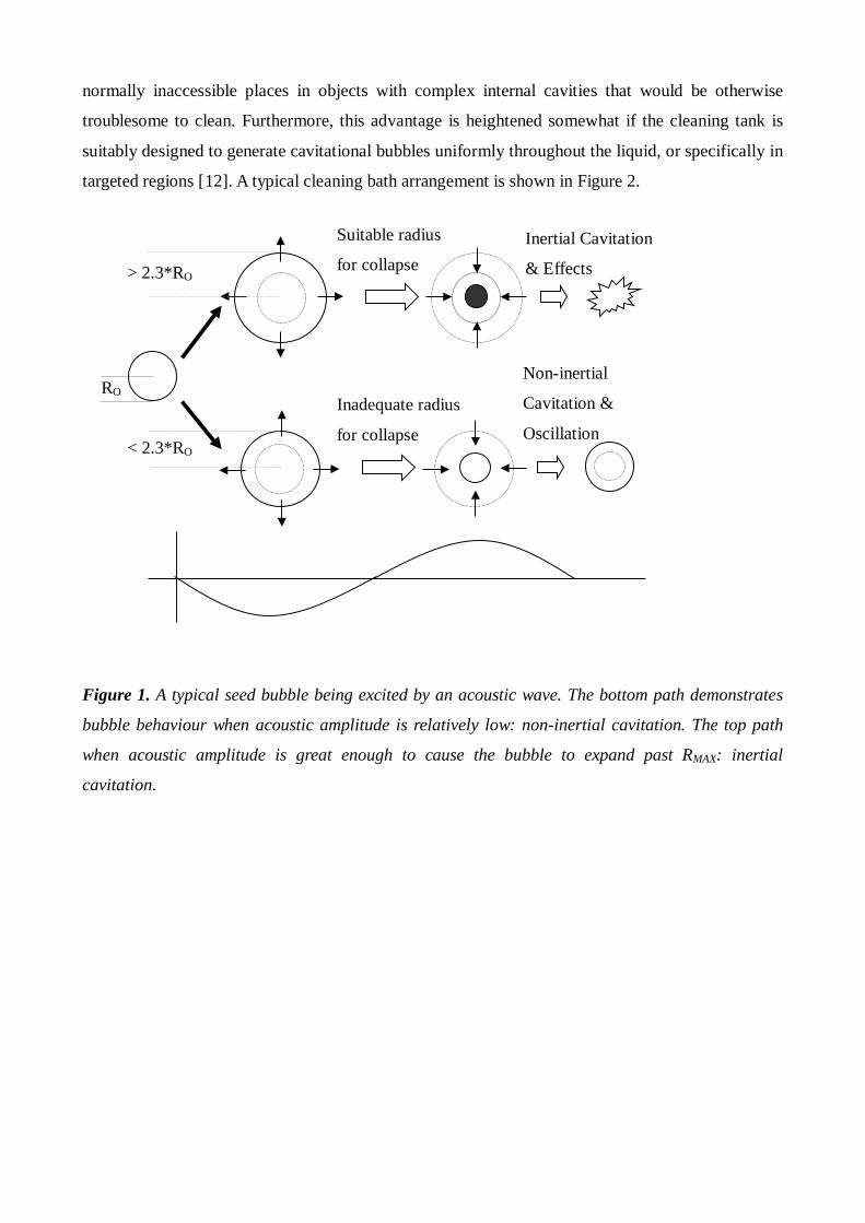
normally inaccessible places in objects with complex internal cavities that would be otherwise
troublesome to clean. Furthermore, this advantage is heightened somewhat if the cleaning tank is
suitably designed to generate cavitational bubbles uniformly throughout the liquid, or specifically in
targeted regions [12]. A typical cleaning bath arrangement is shown in Figure 2.
Figure 1. A typical seed bubble being excited by an acoustic wave. The bottom path demonstrates
bubble behaviour when acoustic amplitude is relatively low: non-inertial cavitation. The top path
when acoustic amplitude is great enough to cause the bubble to expand past RMAX: inertial
cavitation.
RO
> 2.3*RO
< 2.3*RO
Suitable radius
for collapse
Inadequate radius
for collapse
Inertial Cavitation
& Effects
Non-inertial
Cavitation &
Oscillation

Figure 2. Typical ultrasonic cleaning bath arrangement featuring 3 transducers fixed to the bottom
of a container.
Ultrasonic cleaning is more effective on hard materials such as metals, glass, ceramics and plastics,
which have a much higher acoustic impedance compared to water so that ultrasound is reflected in a
manner that reinforces the pressure at the surface. Typical power densities utilised in most cleaning
applications are relatively low compared to other high intensity operations e.g. welding. Counter-
intuitively, attempts to transmit more energy into the load medium can hinder many of the
beneficial aspects of the cavitational effects. Increased cavitation will be produced at the active
faces causing disruption to the acoustic energy flow into the system and dramatically reducing the
uniformity of the bubble density in the load, not to mention the increased damage to the transducers
due to locality of collapsing bubbles. This presents an obvious need for well designed vessels to
ensure the solution to inefficient cleaning operations is not to simply increase the drive power [13].
The majority of high intensity applications function at relatively low frequencies and ultrasonic
cleaning is no exception. Operational frequencies generally range from 20 to 50 kHz depending on
the task. For example, a 25 kHz cleaner will have more cleaning prowess than a 50 kHz cleaner
since the likelihood of cavitational effects is higher at lower frequencies. However, lower
frequencies can prove damaging to delicate parts hence 50 kHz and above may be preferable for
some applications, i.e. the semiconductor industry. In terms of health and safety, higher frequency
cleaners are also quieter due to the lack of energy in the audible range [14].
Ultrasonic cleaning has also been applied to non-conventional materials with porous structure. In
particular, it was reported that ultrasonic cleaning might have significant advantages for textile
Transducers
Vessel containing material to be cleaned
Water
Ultrasonic Bath

processing as it is a wet process, with significant benefits apparent when measured with reflectance
values for merit [15]. The method deployed uses a plate transducer very near or in contact with the
wetted textile to ensure cavitation within the textile structure [16]. Moreover, it has been shown that
by making certain preparations to the process, ultrasonic cleaning of textile materials in a domestic
setting provided significant performance advantage to conventional washing [16, 17].
Ultrasound has recently been shown to be beneficial in cleaning boats that normally require the
expensive annual procedure of dry docking. This is an essential operation to be completed regularly,
as the layer of contaminant becomes adhered to the surface of the boat and would have to undergo a
further cleaning operation involving sanding of the boat surface. Therefore, ultrasound may be
considered an effective method of maintaining a boat, relatively cheaply [18]. It was demonstrated
that the transducer had to be very close to the surface of the boat for the cleaning to be effective,
and thus the system required good position/orientation control of the active device.
Ultrasonic cleaning has also found application in the treating of oak barrels for wine production
which make up the largest cost expenditure after grapes. Cleaning with ultrasound was shown to be
superior to an industry standard method of high pressure, hot water, mechanical cleaning; achieving
full removal of tartae deposits and an above 95% kill of spoilage yeast compared to the
corresponding 30% and 20% results for the conventional method. Moreover, it was observed that
the high power ultrasound had no effect on the internal structure of the oak wood therefore
maintaining oak integrity. The uniform cleaning afforded by this method thereby extends the barrel
life considerably, which resulted in the greatest amount of oak flavour compounds being available
[19].
Importantly, high power ultrasound continues to find new applications as an effective cleaning tool
in diverse industrial processes [20,21].
Welding
One other major, long-established application of power ultrasonics that has successfully permeated
industry is the welding of thermoplastic joins with high intensity ultrasonic devices. The process
itself progressed very quickly from the development stage in the 1960’s to widespread use in the
assembly of toys, appliances, and industrial thermoplastic parts by the early 1970’s [11]. It is an
ideal technique for modern manufacturing; the process is fast and clean, does not need a skilled
operator, requires no consumables and lends itself readily to automation for mass-produced parts
where plastics have replaced metals and glass as the main resource.
Plastic welding is primarily a thermal operation; the local temperature around the target join is
increased to sufficient levels to allow welding due to the mechanical stresses generated by the high
power ultrasonic equipment. However, unlike conventional thermal techniques there is no
indiscriminate heating of the surrounding material and hence no unwanted component distortion.
This advantage is partly due to the fact that most thermoplastics exhibit favourable characteristics
for ultrasonic welding i.e. the ability to transmit and absorb acoustic energy, as well as low thermal
conductivity. In addition, since the heat is generated within the materials and transferred via the
ultrasonic tool, it is entirely possible to accomplish welds in places that would otherwise be
inaccessible to conventional welding methods.
Ultrasonic welding uses comparable frequencies to other power applications described in this
Section (~20 kHz), but differs in several ways; the functionality is not reliant of the effects of
cavitation, much higher power densities are required, e.g. over ten times that which is used for
cleaning, and the application of acoustic energy is delivered through an ultrasonic horn.
Optimisation in the development of this technology is primarily achieved through improvement and
innovation in horn design as opposed to acoustic field mapping techniques [22].
A similar application has also been found with sheet metal welding, a solid state process in which
the materials are held together while applying high power shear ultrasonic waves. This
differentiates it from polymer welding in which the direction of ultrasonic oscillation is in the
direction perpendicular to the weld surfaces [23]. It results in a true metallurgical bond occurring
below the melting points of the work pieces in a process similar to cold welding. It has been shown
to be particularly advantageous where the materials to be welded have different chemical and
physical characteristics such that conventional methods are not appropriate [24, 25]. It has also
shown great potential for application in composite material manufacture [23, 26].
The ultrasonic welding process has been progressed further to introduce new processes within
manufacturing: Ultrasonic Compounding or Ultrasonic Additive Manufacturing [27, 28, 29]. In
this new process, foil sheets of metal are progressively layered together with associated cut-outs or
embedded materials included and ultrasonically welded sequentially until a composite 3-
dimensional object has been created. This new method presents certain advantages on conventional
manufacturing methods such as increased safety due to absence of sparks, capacity for automation
although research is still being undertaken on optimising the technique. The method achieves a
bond without inducing melting resulting in a reduction in the error associated with material change.

It has recently been commercialised, albeit with some practical limitations mainly due to tool
failure.
Cutting
The cutting of various materials, from bone to confectionery, using ultrasonic methods has
advantages over conventional cutting mechanisms [30]. For example, applying standard non-
ultrasonic cutting methods to soft products can result in a great deal of waste produce and imprecise
performance. Performing such tasks with an ultrasonically excited blade allows highly precise cuts,
very little waste and improved process times. Furthermore, in the medical industry a great deal of
interest surrounds the cutting of bone with ultrasonic saws. Conventional cutting causes problems
for patients and doctors alike; rough cuts, unwanted heat and bone particles embedding themselves
in neighbouring soft tissue are some of the main issues, although in other applications this
generated heat can prove useful [31, 32].
Typically ultrasonic blades are designed to resonate in the longitudinal mode of vibration in the
range of 20-40kHz. However, problems with blade durability and inefficient coupling of energy in
the system are present in many operations of this technology. Nonlinear modal coupling with other
less desirable modes of operation and high stress conditions at specific regions of the structure
compared to others are some of the main causes for blade failures [33]. Indeed, these efficiency
problems are similar to those encountered in other high power ultrasound applications.
For this reason, recent research has focussed on optimising the design of these components through
extensive FE modelling and accurate vibrational and stress measurement tools [34, 35]. These are
used to create virtual prototypes of blade designs which are then modified to reduce spurious mode
excitation and limit regions of adversely high stress. Novel multiple blade designs have been
constructed that demonstrate this premise [36], and this work has been further extended into the
medical field to help develop a new generation of bone saw that will reduce large vibrations and
minimise temperature increases [37, 38]. Ultrasonic cutting has been suggested for application in
the drilling of hard surfaces where conventional rotary drills might have disadvantages due to
operational temperature, preload requirement or power consumption as found in space exploration
missions [39].
C. Sonochemistry
Sonochemistry is a burgeoning discipline within the ultrasonics community, although it would be
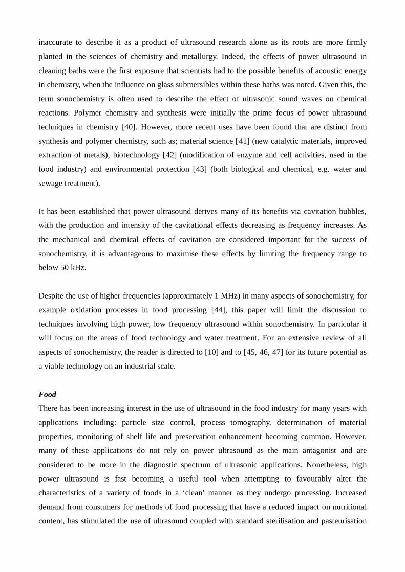
inaccurate to describe it as a product of ultrasound research alone as its roots are more firmly
planted in the sciences of chemistry and metallurgy. Indeed, the effects of power ultrasound in
cleaning baths were the first exposure that scientists had to the possible benefits of acoustic energy
in chemistry, when the influence on glass submersibles within these baths was noted. Given this, the
term sonochemistry is often used to describe the effect of ultrasonic sound waves on chemical
reactions. Polymer chemistry and synthesis were initially the prime focus of power ultrasound
techniques in chemistry [40]. However, more recent uses have been found that are distinct from
synthesis and polymer chemistry, such as; material science [41] (new catalytic materials, improved
extraction of metals), biotechnology [42] (modification of enzyme and cell activities, used in the
food industry) and environmental protection [43] (both biological and chemical, e.g. water and
sewage treatment).
It has been established that power ultrasound derives many of its benefits via cavitation bubbles,
with the production and intensity of the cavitational effects decreasing as frequency increases. As
the mechanical and chemical effects of cavitation are considered important for the success of
sonochemistry, it is advantageous to maximise these effects by limiting the frequency range to
below 50 kHz.
Despite the use of higher frequencies (approximately 1 MHz) in many aspects of sonochemistry, for
example oxidation processes in food processing [44], this paper will limit the discussion to
techniques involving high power, low frequency ultrasound within sonochemistry. In particular it
will focus on the areas of food technology and water treatment. For an extensive review of all
aspects of sonochemistry, the reader is directed to [10] and to [45, 46, 47] for its future potential as
a viable technology on an industrial scale.
Food
There has been increasing interest in the use of ultrasound in the food industry for many years with
applications including: particle size control, process tomography, determination of material
properties, monitoring of shelf life and preservation enhancement becoming common. However,
many of these applications do not rely on power ultrasound as the main antagonist and are
considered to be more in the diagnostic spectrum of ultrasonic applications. Nonetheless, high
power ultrasound is fast becoming a useful tool when attempting to favourably alter the
characteristics of a variety of foods in a ‘clean’ manner as they undergo processing. Increased
demand from consumers for methods of food processing that have a reduced impact on nutritional
content, has stimulated the use of ultrasound coupled with standard sterilisation and pasteurisation

methods for microbe inactivation. Power ultrasound in conjunction with thermal and chemical
techniques has been shown to reduce the numbers of many bacteria such as Salmonella and E. coli
[48]. Other beneficial uses of power ultrasound in the food industry include; sterilisation, extraction
of tea solids from leaves, tenderising of meat products, assisted crystallisation (freezing), degassing
through numerous bubble collapses induced by cavitation. Excellent reviews of all aspects of
ultrasound in food processing are provided in [49,50].
Since the observation of the advantages ultrasound assisted crystallisation offers in terms of grain
consistency and reduced size interest has been shown in using this property towards food
processing. Freezing is an effective means of preserving food as, in many cases water, is a key
constituent material. Subsequently, ultrasound assisted freezing techniques have been investigated
and can introduce significant cost savings. Conventionally, freezing consistently results in some
form of loss of quality of the food product, particularly muscular tissue. This is minimised
depending on what type of crystals are formed in the water with smaller crystals resulting in
minimal loss of quality [51]. This has been linked to increasing ultrasonic power to produce smaller
crystals in the freezing process [52, 53].
Recent research has looked at altering the properties of food. Viscosity of starchy foods has been
decreased significantly after gelatinisation by the application of ultrasound through
depolymerisation of starch polysaccharides [54]. Since starches are widely used, this application
has significant commercial potential. High power ultrasound has also been found to be an effective
processing tool for dairy products compared to conventional methods in terms of quality of the end
product. Yoghurt made by sonically heating milk was found to have superior properties to that made
by conventional heating [55].
Water Processing
Perhaps one of the most beneficial applications of ultrasonic processing for society is the potential
for its use in the water and sewage treatment. The destruction or transformation of organic
pollutants and the removal of biological contaminants are the fundamental objectives of
investigations involving ultrasound. Until recently, it was thought power ultrasound would be too
expensive as a viable technology to use for water treatment on an industrial scale. This was based
on the direct scale up of power consumption in small-scale laboratory experiments. However, recent
research has suggested that the decontamination of water through ultrasonic techniques in
conjunction with other treatments may be feasible when applied to flowing systems [56, 57].
Regarding water treatment, two examples of removing biological contamination from the water
have been implemented on a large scale basis; inactivation of plankton clogging filters in water
distribution systems; and the destruction of algal blooms [58]. The former demonstrated satisfactory
results in plankton inactivation using economic power levels and a flow through system, while the
latter demonstrated that ultrasonic treatment offers the potential to not only kill the micro-organism
but also severely restrict its reproductive ability. In sewage sludge treatment, ultrasound is often
applied as pre-treatment to enhance the time-consuming and inefficient conventional processes,
without the requirement for relatively large amounts of power to be transmitted [47, 59]. The
benefits of ultrasonic pre-treatment with application to contaminant removal has also been
considered for other areas, such as distillery wastewater [60], although a conventional ultrasonic
bath was used in the experimental analysis. Furthermore, in cases were a filtration membrane forms
an intergral component of the treatment process, ultrasound can be used to control membrane
fouling [61, 62].
3. Measurement Methods
High power ultrasonic fields can be extremely difficult to characterise, often due to the cavitational
activities themselves. Not only can cavitational effects cause damage to any measurement
instrumentation being used, but regions of dense bubble populations can also scatter the source
acoustical signal under investigation. This often facilitates measurements being obtained under non-
cavitational conditions. Nevertheless, conducting measurements in non-cavitating fields may not
yield true pressure distribution experienced during a high power application, but it can identify
locations where cavitational sites are likely to occur when sufficient power levels are reached.
Traditionally, hydrophones are the principal device for field characterisation in many applications
with use in medical ultrasound for exposure quantification widely reported. There are a number of
important factors to consider in hydrophone design whether it is piezoelectric ceramic based or,
more recently, piezoelectric polyvinylidene fluoride (PVDF) membrane. The device itself should be
non-perturbing to the acoustic field in order to minimise any detrimental effect on the field profile,
although the physical nature of the probe makes complete non-invasive measurement impossible in
reverberant environments. Furthermore, many hydrophones suffer from a lack of uniform response
over a wide range of frequencies while still maintaining sensitivity, particularly below 200 kHz
where the majority of high power applications operate. In addition, any measurement probe must be
robust enough to withstand the hostile fields associated with high power ultrasound measurement,
where PVDF membrane devices in particular are very susceptible to damage. Notwithstanding,
hydrophone devices by their very nature generally can be quite delicate and fragile as designs strive
to attain increased levels of sensitivity, spatial resolution and non-invasiveness, making damage to
the active element is the main concern. This may explain the lack of literature available on the use
of hydrophones for the measurement of acoustic fields generated by high power applications, with
the exception of lithotripsy in the medical field where apprehensions over safety has facilitated the
development of robust probes, at the expense of sensitivity [63]. This has led to the development of
the more durable optical fibre hydrophone that demonstrates marked improvements in both spatial
resolution and sensitivity over conventional counterparts [64]. Nonetheless, these devices still
require insertion into the load medium causing a direct impact on the pressure fields present and on
subsequent measurements. Manipulation of probe position within a sealed container is also very
problematic and is not conducive to obtaining accurate field profiles. This difficulty in taking
precise measurements leads to subsequent problems in validating any simulation data that may be
available for comparison.
Distinct from measuring the ultrasonic/acoustic field distribution, is the ability to measure
cavitation intensity. Cavitating bubbles behave as acoustic sources when collapsing emitting
harmonics and sub-harmonics of the acoustic drive frequency, in addition to high frequency
acoustic emission signals. Hydrophones positioned inside, or fixed on the outside, of the container
are able to pick up the acoustic signatures of the bubble dynamics [65, 66]. The amplitude, phase
and frequency information of these signals can provide data on the scale and nature of bubble
activity. However, in many applications it is important to be able to obtain spatial knowledge of the
cavitation field and a cavitation monitoring sensor has been developed for this purpose [67, 68].
It should be noted that other, less popular techniques will not be covered in this article. Some of the
more common ones are listed for the readers’ interest: radiation pressure balances [4], holography
[69], chemical detection [7], and thermal measurements [14]. Of these, thermal methods have been
used with some success in high power field measurements to provide a simple means of evaluating
the power in an ultrasonic cleaning bath.
A. Piezoelectric Ceramic Hydrophones
Piezoelectric hydrophones are detectors based on transducers which respond directly to pressure
variations in a load according to the direct piezoelectric effect [70]. The Curies discovered that a
mechanical deformation applied to a quartz crystal resulted in an electric charge being produced on
the surface, where, in terms of acoustic measurement, the mechanical deformation is the acoustic
disturbance. Later, the inverse piezoelectric effect was discovered [71], in which if a piece of quartz
is subjected to an electric field across it then a mechanical deformation will occur. Since the 1950’s,
modern piezoelectric materials exhibiting more advantageous characteristics for the transmission
and reception of acoustic signals have superseded quartz as the active material.
A conventional piezoelectric ceramic hydrophone schematic is shown in Figure 3. It is comprised of
an active piezoelectric element, a backing block for damping and a matching layer. The matching
layer and the backing block serve to optimise the characteristics of the probe by both widening
bandwidth and increasing sensitivity [72], although there exists a permanent trade-off between the
two. There are a number of important factors to consider in hydrophone design, particularly the
piezoelectric ceramic variant. Firstly, the device should be relatively non-perturbing; this becomes
more of an issue at higher frequencies due to the corresponding decrease in acoustic wavelength.
Nevertheless, for some lower frequency applications it would not be desirable to disrupt the
standing wave patterns integral to the process through the introduction of a measurement probe.
Secondly, the device should also have a uniform frequency response over the bandwidth under
scrutiny, while maintaining reasonable sensitivity. Again, this can prove more of a problem in
characterising high frequency (> 3 MHz) medical diagnostic equipment, or in the measurement of
very short transient signals associated with the pulsed operation of such devices. This will not be
the case in the realm of power ultrasonics. However, sensitivity at frequencies in the region of
20kHz is often well outside the normal 3dB range of many typical hydrophone probes [73] and
custom designed probes must be considered in these instances.
Piezoelectric ceramic composites (commonly known as piezocomposites) address many of the
disadvantages associated with monolithic piezoelectric ceramics i.e. high acoustic impedance,
limited bandwidth, spurious modes dependent on physical geometry, while retaining the advantages
of high electromechanical coupling and high permittivity. These benefits are achieved via dicing the
ceramic in two orthogonal directions and filling with a passive polymer phase to give a
configuration known as a 1-3 connectivity configuration [74]. This is a common choice for low
frequency measurement probes, in particular for SONAR applications [75].
Nevertheless, it should be noted that piezocomposite hydrophones will be subject to the same
shortcomings as monolithic probes when used for the characterisation of high power fields, i.e.
perturbation of the field and potential damage due to cavitation. The advent of piezoelectric
polymers offered an alternative, and potentially superior, technology for quantifying acoustic

pressures.
Figure 3. Arrangement for a typical piezoelectric probe.
B. PVDF Devices
While ceramic and piezocomposite hydrophones are adequate for characterising CW or narrow
band tone burst fields used in therapeutic applications, the dimensions of the active piezoelectric
element and probe housing make them intrinsically multi-modal and unsuitable for measuring
broadband diagnostic pulses. Nevertheless, the discovery of piezoelectricity in the polymer PVDF
by the Japanese in 1969 provided the potential for pressure sensors without the problems associated
with the ceramic devices. The main advantages of using PVDF as a sensor over ceramic are; an
improved acoustic impedance match to water and tissue, its availability in thin flexible sheets and a
linearly broadband, flat frequency off-resonance response. Admittedly, PVDF devices are primarily
geared for use in the medical field and this has indeed been the cause of their emergence over the
years with PVDF now the established ‘gold-standard’ sensing material for hydrophone based
measurements in the biomedical industry. There is potential to use such devices in a high power
environment under suitable circumstances i.e. avoiding contact with regions of cavitation. PVDF
hydrophones are typically categorised as membrane devices, however, PVDF can also feature as the
active element in needle-type devices, in addition to piezoelectric ceramic with the former now
Electrical Connection
Backing Block
Matching Layer
Piezoelectric element
Housing
+ ve - ve
being more common. An excellent review of PVDF’s influence on medical ultrasound field
techniques and standards can be found in Harris’ comprehensive article [76].
Membrane Devices
As PVDF film is available in large, thin (typically 5 to 110µm thick), flexible sheets of similar
acoustic impedance to water, it is a natural choice for designing hydrophones for acoustic field
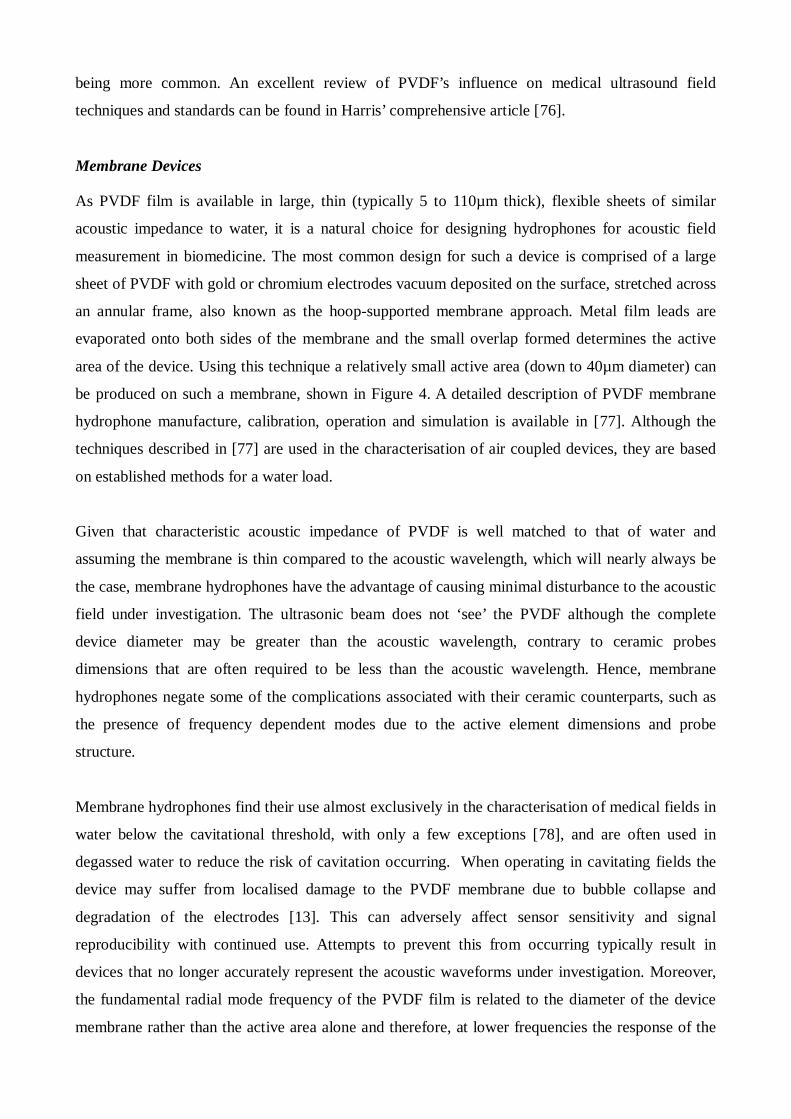
measurement in biomedicine. The most common design for such a device is comprised of a large
sheet of PVDF with gold or chromium electrodes vacuum deposited on the surface, stretched across
an annular frame, also known as the hoop-supported membrane approach. Metal film leads are
evaporated onto both sides of the membrane and the small overlap formed determines the active
area of the device. Using this technique a relatively small active area (down to 40µm diameter) can
be produced on such a membrane, shown in Figure 4. A detailed description of PVDF membrane
hydrophone manufacture, calibration, operation and simulation is available in [77]. Although the
techniques described in [77] are used in the characterisation of air coupled devices, they are based
on established methods for a water load.
Given that characteristic acoustic impedance of PVDF is well matched to that of water and
assuming the membrane is thin compared to the acoustic wavelength, which will nearly always be
the case, membrane hydrophones have the advantage of causing minimal disturbance to the acoustic
field under investigation. The ultrasonic beam does not ‘see’ the PVDF although the complete
device diameter may be greater than the acoustic wavelength, contrary to ceramic probes
dimensions that are often required to be less than the acoustic wavelength. Hence, membrane
hydrophones negate some of the complications associated with their ceramic counterparts, such as
the presence of frequency dependent modes due to the active element dimensions and probe
structure.
Membrane hydrophones find their use almost exclusively in the characterisation of medical fields in
water below the cavitational threshold, with only a few exceptions [78], and are often used in
degassed water to reduce the risk of cavitation occurring. When operating in cavitating fields the
device may suffer from localised damage to the PVDF membrane due to bubble collapse and
degradation of the electrodes [13]. This can adversely affect sensor sensitivity and signal
reproducibility with continued use. Attempts to prevent this from occurring typically result in
devices that no longer accurately represent the acoustic waveforms under investigation. Moreover,
the fundamental radial mode frequency of the PVDF film is related to the diameter of the device
membrane rather than the active area alone and therefore, at lower frequencies the response of the
device is no longer flat [79]. This may cause difficulties when attempting to characterise the low
frequency fields generated in the majority of high power applications, even under the assumption
that cavitation within the load has been minimised.
Figure 4. Membrane hydrophone arrangement
Needle Devices
Needle-type hydrophones generally consist of an active element approximately 0.5 mm in diameter,
more commonly PVDF film but occasionally piezoelectric ceramic based, mounted onto the end of
a hollow cylindrical tube with an outside diameter close to that of the active element. The cylinder
is filled with an acoustically absorbing material (backing) with an acoustic impedance much greater
than that of the membrane. The outer surface of the cylinder is connected electrically to the film
surface and the inner surface is attached to an insulated wire placed inside the tubing. Figure 5
depicts the arrangement of a typical needle hydrophone.
Supporting Ring
Active Region
PVDF Membrane
Electrical Connection
Coating on underside
Wire
Coating on top

Figure 5. Arrangement for a typical needle hydrophone where the active element can be PVDF or
ceramic based.
The design of needle-type hydrophones incorporating PVDF as the active element is very similar to
the ceramic based designs, but with exceptionally contrasting frequency responses. Indeed, ceramic
needle hydrophones can experience unpredictable structure in both their directional and frequency
responses due to radial resonance modes, reflections and mode conversions in the active element
and backing material. The geometry of the needle-type probe has afforded it some unique
advantages over its membrane and ceramic counterparts; it is easily adaptable for measurements in
confined spaces such as in-vivo; in situations involving measurements near the source or under CW
excitation, where membrane probes may generate unwanted reverberations, the needle hydrophone
provides a cleaner signal with less perturbation of the field, and for certain transducer geometries
within an enclosed environment, the needle hydrophone has better access than other types of
devices. The difference between a membrane and needle hydrophone placed in a CW field is
investigated in [80] with the needle probe demonstrating less disturbance to the harmonic field.
Another notable advantage of the needle hydrophone is that a well designed probe can exhibit a
directivity pattern that is close to an ideal piston. These devices are also fairly robust, making them
viable suitors for the transition from medical applications to the characterisation of high power
fields in a lower frequency regime. However, the presence of radial modes at lower frequencies due
to membrane/ceramic geometry; deterioration of the contact between the wire and active element
over time and a roll-off in the low frequency response caused by diffraction at the tip are concerns
for low frequency measurements.
Thin Wire
Acoustically absorbing backing material
Housing
Active element: PVDF or Piezoelectric
C. Fibre Optic Devices
The proposition of using light to detect and quantify an acoustic field is not a new one. Extensive
literature exists dating back to the 1930’s with the initial observations of Debye and Sears, and
Lucas and Biquard on the diffraction of light by an ultrasonic field [81] lead to the start of a field
known as acousto-optics. It could even be said that the first interaction between sound and light pre-
dates the previously mentioned publication as flames were used in the 19th century as a qualitative
measurement of an acoustic wave [82]. This paper is focussed on the use of probes incorporating
optics for the characterisation of ultrasonic fields for a range of applications, while emphasising
their potential for high power measurement.
Field measurements by fibre-optic devices have the potential to overcome some of the problems
associated with conventional piezoelectric or PVDF hydrophones. Optical methods can offer the
following: minimal intrusion of the field, reduced element size of several microns limited only by
the diameter of the optical fibre, near omni-directional response, linear broadband frequency
response, relative manufacturing ease and a degree of ruggedness not often associated with the
conventional probes. Furthermore, an optical sensor known as a laseroptic hydrophone [83] has
been shown to provide information on cavitation occurring near the active element. This device
merely consists of light from a laser diode coupled into a glass optical fibre, of 50µm diameter, with
the end placed into the load medium. A photodiode is utilised to detect the light reflected back along
the core from the glass/water boundary. Assuming an acoustic wave is incident upon the end of the
fibre, the density and hence refractive index of the water at the fibre will be modified in proportion
to the compression phase of the wave, therefore modulating the amount of light reflected at the
boundary. The sharp discontinuity in refractive index caused by the presence of an air bubble
created by cavitation is easily detected by the sensor. A similar device for use in the measurement of
shockwaves displays a similar resistance to bubble collapse near the active element [84].
There are two types of optical sensor that are generally used for ultrasonic field characterisation;
probe based systems that rely on a physical change to detect pressure, i.e. deformation of a surface;
and non-invasive systems that are based on the diffraction of light by an acoustic field. The former
variety is known as a fibreoptic hydrophone and demonstrates potential in both conventional and
high power field characterisation [64, 85]. Of this variety there are there are two designs of merit;
the laseroptic probe discussed previously, and a more subtle design featuring a polymer film at the
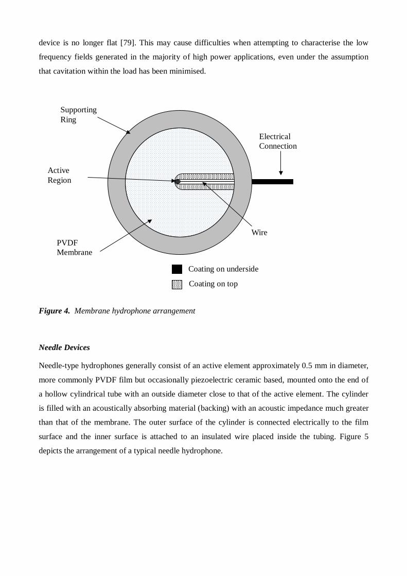
end of an optical fibre, shown in Figure 6. The device itself consists of 25µm thick polymer film
deposited onto the end of a single mode optical fibre, diameter 6µm. Two aluminium mirrors are
evaporated onto the fibre end and the polymer with reflective coefficients of 8% and 70%,
respectively. The active area of the probe is approximately equal to the optical fibre diameter and all
other important dimensions can be found in Figure 6. The detection mechanism is based upon the
acoustically induced changes in the optical thickness of the polymer film acting as an
interferometer. Significantly, this device demonstrates sensitivity levels comparable to a much
larger PVDF membrane device (0.2mm2 active area), while offering lower directional sensitivity
than that of a PVDF needle device (0.075mm2 active area). Due to the ease of manufacture for such
a probe, disposable sensor heads could be developed to make characterising high power fields
economically viable in terms of potential damage to the sensors inserted into these hostile
environments.
Figure 6. Arrangement for a fibre optic polymer film hydrophone.
The other variety of fibre optic sensor is based on the diffraction of light by ultrasound. These
probes are essentially non-invasive as they do not interact with the acoustic beam, unless used in a
reverberant environment. Functionality of these sensors is based on Raman-Nath light diffraction
[86], which states that when a beam of light passes through an acoustic field, diffraction of the light
beam takes place and by measuring the amplitude and frequency of the detected beam, information
about the acoustic field can be extracted. In essence, the acoustic field acts as a diffraction grating.
In contrast to other ultrasonic hydrophones that require to be placed in the acoustic field, this
technique requires no physical interaction with the acoustic beam, and hence, does not perturb the
field [87]. The transmitting optical fibre is placed in a water tank perpendicular to the acoustic beam
axis and on the same plane as the focal region of the transducer. The receiving fibre is placed
directly opposite with a gap of approximately 15 mm separating the two. The detected diffraction
patterns are coupled into an avalanche photodiode and the electrical signal displayed on an
oscilloscope, as shown in a simple schematic in Figure 7. Sensitivity for this technique is reported
250
um
300
um
125
um
Silica Cladding ~ 25 um thick membrane
70% Reflective coating
8% Reflective coating
6 um thick
Housing Buffer
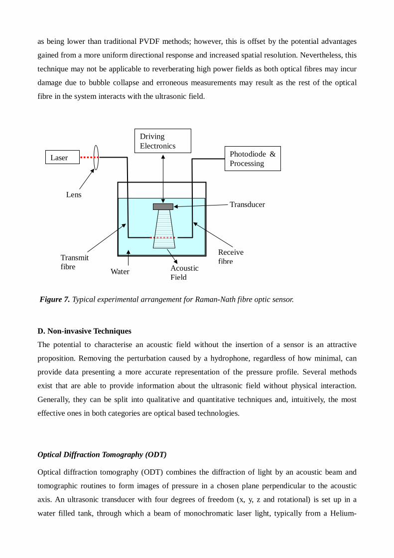
as being lower than traditional PVDF methods; however, this is offset by the potential advantages
gained from a more uniform directional response and increased spatial resolution. Nevertheless, this
technique may not be applicable to reverberating high power fields as both optical fibres may incur
damage due to bubble collapse and erroneous measurements may result as the rest of the optical
fibre in the system interacts with the ultrasonic field.
Figure 7. Typical experimental arrangement for Raman-Nath fibre optic sensor.
D. Non-invasive Techniques
The potential to characterise an acoustic field without the insertion of a sensor is an attractive
proposition. Removing the perturbation caused by a hydrophone, regardless of how minimal, can
provide data presenting a more accurate representation of the pressure profile. Several methods
exist that are able to provide information about the ultrasonic field without physical interaction.
Generally, they can be split into qualitative and quantitative techniques and, intuitively, the most
effective ones in both categories are optical based technologies.
Optical Diffraction Tomography (ODT)
Optical diffraction tomography (ODT) combines the diffraction of light by an acoustic beam and
tomographic routines to form images of pressure in a chosen plane perpendicular to the acoustic
axis. An ultrasonic transducer with four degrees of freedom (x, y, z and rotational) is set up in a
water filled tank, through which a beam of monochromatic laser light, typically from a Helium-
Laser
Driving Electronics
Photodiode & Processing
Lens Transducer
Transmit fibre
Receive fibre
Water Acoustic Field
Neon source, is transmitted. The diffracted light signal exiting the tank is received by a
photodetector, where the demodulated intensity is proportional to the average pressure through the
width of the field. By taking a series of parallel measurements as described and then rotating the
transducer in monotonic angles through 180 degrees, simple tomographic reconstruction algorithms
can then be implemented to create an image of pressure at an arbitrary distance from the source
[88, 89, 90, 91, 92]. This technique is completely non-invasive and has the potential for obtaining
greater spatial resolution than hydrophone methods. Moreover, the absence of a detector in the field
enables accurate measurement of the acoustic nearfield without the presence of unwanted
reflections.
Interferometry
Laser interferometry has been employed in two distinct ways for ultrasonic field characterisation.
The first manner is similar to ODT as tomographic scanning routines are used to generate images of
pressure, but different in that the phase modulation due to the light traversing the acoustic
disturbance twice is used to evaluate pressure. This method can also be extended for non-invasive
measurement of ultrasonic fields in sealed cylindrical vessels through an augmentation of the
tomographic scanning routines. The main difficulty in employing tomography in this manner is the
breakdown of the parallel shots required for the reconstruction algorithm due to refraction of laser
light at the vessel wall boundaries (assuming a non-opaque material such as glass or perspex is
used). However, it is possible to correct for such refraction if the incident angle of the laser light is
altered to ensure the path through the field results the re-establishment of the necessary parallel
shots. Given this, conventional tomographic reconstruction algorithms can then be utilised to form
3D pressure maps of the internal field. Such a technique is described in more detail in [93]. The
other method is based on quantifying the displacement of a membrane caused by an acoustic field,
and will also be described here.
It would be inaccurate to describe this second arrangement as a pure non-invasive field
characterisation technique as a thin plastic reflective membrane (known as a pellicle) is placed in
the path of the acoustic beam. One surface of the pellicle reflects the optical beam of a laser
interferometer, which is used to determine the absolute displacement of the membrane and hence of
the acoustic field. From this displacement measurement, the absolute acoustic pressure can be
calculated. As the influence of the pellicle (of similar dimensions to a PVDF hydrophone) on the
field is minimal and, as such, this method is categorised with other non-invasive techniques for the
purposes of this review. Primarily utilised as a reliable means of calibrating hydrophones [94], this
technique was later adapted for pulsed field characterisation [95], and then expanded upon by
incorporating a 3D mechanical scanning system for transducer movement to facilitate complete
field mapping, if desired [96]. With regard to high power field measurement, damaging the fragile
membrane would pose the most significant problem.
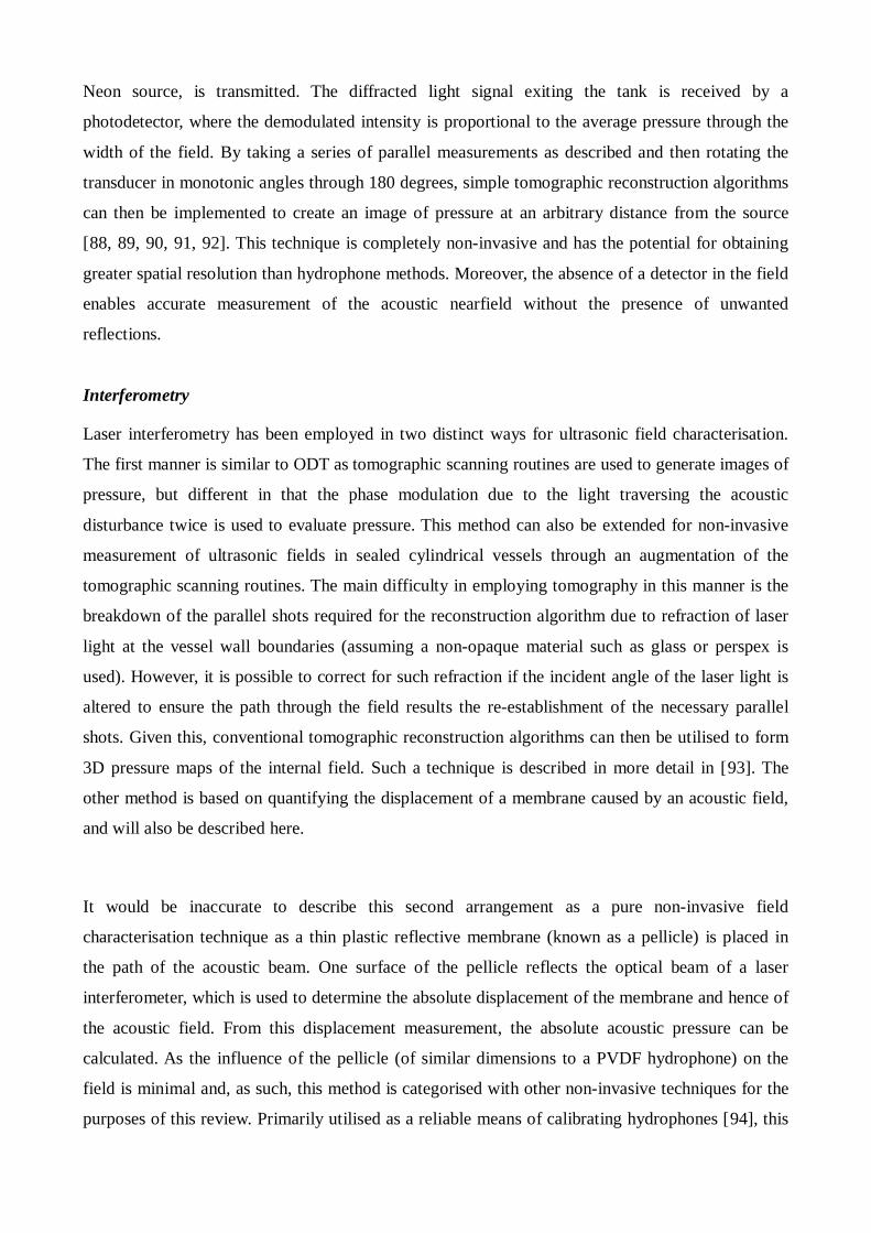
Schlieren
Schlieren imaging of ultrasonic waves is traditionally a qualitative technique that has proven useful
for the visualisation of acoustic beams incident upon and reflected from various surfaces. The basic
theory behind a Schlieren system is from Raman and Nath’s treatment on the diffraction of light by
sound [86], in that a propagating sound wave induces a change in the refractive index of the
transmission medium, causing the sound wave to behave like a diffraction grating. The intensity of
the subsequent diffraction pattern is proportional to the integral of pressure along the light path.
Therefore, the intense pressures in the beam are represented as greater intensities in the optical
signal received as the light passes through the field. A simple Schlieren system is shown in Figure 8.
This can be utilised to produce striking images of acoustic fields under free field conditions and
reflecting from a surface.
Since Schlieren visualisation requires a transparent medium for operation the obvious limitation is it
must be used in conjunction with a non-opaque load fluid. Furthermore, it does not accurately
represent the pressure field as it forms a 2D measurement from a 3D sample.
Figure 8. Experimental arrangement for a conventional Schlieren system.
CCD camera
Laser
Water filled tank
Acoustic Source
Laser Vibrometry
This method is a novel utilisation of laser scanning vibrometry, based on interferometric principles,
that has been applied with great success in the measurement of the vibrational displacement in a
variety of transducers [97,79]. By placing the transducer in a tank with the acoustic axis
perpendicular to the laser light and securing retro-reflective material to the other side of the tank, it
is possible to measure the average change in refractive index through the width of the beam. In this
manner, a complete scan of the average intensity of the acoustic beam can be generated [98].
Providing gated excitation is used and reverberations minimised, this technique can provide a
reasonably accurate spatial representation of the acoustic intensity distribution from an ultrasonic
device. However, the refraction of the incident laser light by the tank walls may introduce some
measurement errors if not accounted for. This methodology also suffers from the same difficulties
as conventional Schlieren imaging as a 2D image is formed from a 3D data set, though tomographic
techniques could be employed to remedy this.
E. Cavitation Monitoring techniques
Until recently, the measurement of cavitation has been a particularly troublesome problem. Some of
the difficulties in measuring cavitation have been highlighted throughout this paper, difficulties
such as; damage to sensing equipment, large transient signals, hostile environmental conditions,
unpredictability, and difficulty distinguishing between the two types of cavitation. Common
measurement methods include [67,68]; broadband acoustic emission, aluminium foil erosion,
chemical effect monitoring (chemiluminescence) and sonoluminescence. Despite the attractiveness
of these two luminescence techniques and their potential for high spatial resolution, the requirement
for blackout conditions in optically transparent media renders them complex to implement in
practice. Conversely, passive acoustic methods incur none of the complications associated with the
optical techniques and, consequently, are more widely applicable.
Potassium iodide dosimetry has been another method used to measure the intensity through the
oxidation of iodide ions to iodine where they then form a chemical complex with excess iodine to
form tri-iodide [99]. While chemical experiments have their limitations, they have been shown to
give results which correlate closely with those obtained from acoustic emission measurements
[100].
Cavitating bubbles behave as acoustic sources when stimulated by an external acoustic field via
modes generated by the bubble’s non-linear motion, emitting harmonics and sub-harmonics of the
acoustic drive frequency. Hydrophones positioned inside, or fixed on the outside, of the container
are able to pick up the acoustic signatures of the bubble dynamics. The amplitude, phase and
frequency information of these signals can provide data on the scale and nature of bubble activity.
However, obtaining spatial knowledge of the cavitating bubbles for a particular volume of liquid is
difficult with conventional acoustic monitoring. This prompted Zeqiri et al [101, 102] to identify
the attributes desired for a novel cavitation monitoring sensor and develop the device accordingly.
The sensor consists of a thin layer of piezoelectric polymer film attached to the inner surface of a
hollow, open-ended cylinder, providing measurement bandwidth from 0 to 10 MHz. The outer
surface of the cylinder is coated with a specially developed cavitation shield material that is highly
attenuating to acoustic signals at megahertz frequencies. This provides the sensor with a degree of
spatial resolution as any acoustic signals characteristic of acoustic cavitation arise from events
occurring within the cylinder volume. Moreover, the coating material has an acoustic impedance
similar to water therefore ensuring the sensor is minimally perturbing to the field under
investigation. Furthermore, it is possible to increase spatial resolution by reducing the internal
diameter of the sensor, although the current design is limited to measuring cavitation from
ultrasonic transducers operating below 50kHz. A reference cell was developed for which various
cavitation measurement methods could be tested [103] and compared with the results showing
correspondence with the cavitation monitoring sensor.
The effectiveness and utility of the acoustic emission method was demonstrated when it was shown
that acoustic emission levels were related to cytotoxicity levels observed in tissue and as a result a
system that directly controls cavitation through its measurement and a feedback mechanism was
developed with the regulated system showing much improved repeatability as compared to the
unregulated system [104, 66, 105].
4. Discussion
This review paper draws upon a significant body of scientific and engineering research spanning
one hundred years. It complements other high power review publications [7, 13, 40, 45, 50, 106] by
coupling measurement techniques alongside a review of high power applications. As high power
applications develop further, it is clear that calibration and characterisation of the sonification field
will become increasingly important to understand with sufficient accuracy. Moreover, non-invasive
techniques will be sought to ensure no contamination of the load medium and minimal influence on
the generated field by the measurement probe/sensor.
It is clear that there are a diverse range of applications in which high power ultrasound plays a
pivotal role. Interestingly, there are a number of common features between these systems. The
majority of high power ultrasonic systems, for industrial applications, can be categorized as
operating below 100kHz in order to enhance the potential of the system to induce a cavitating field.
Moreover, these systems offer versatility in the deployment of the high power field and hence can
accommodate operation on systems/components with complex geometry. One particular issue is the
scale up from laboratory systems to large volume industrial systems [46, 102], where there can be
degradation in performance especially for systems developed using resonance based design
techniques. Alternative geometries are continually being explored [107] to enhance the industrial
uptake of this ‘green’ technology, which offers an energy efficient process in which the requirement
for additive chemicals can be minimised.
As high power ultrasound finds new applications, the requirement to reliably measure the system
response will increase. Albeit it is important to understand what system parameter requires to be
measured. Field distribution can be determined through a wide range of techniques and is important
in terms of identifying ‘hot-spots’ in the load which offer maximum potential for maintaining a
cavitating field. This is typically measured under low-intensity conditions. Whereas, measuring the
intensity of the cavitating field will relate directly to the influence the ultrasonic system will exert
on a reaction. This is obviously critical from the industrial perspective. Combining these two
measurement quantities provides the design engineer further system optimisation opportunities
[104], although this is not achievable in real-time during the reaction process with current
technology.
To conclude, it is important to mention the health and safety risks associated with high power
ultrasonic systems. It is considered that for each application from small scale, laboratory based
reactors through to large industrial scale systems, due care will be given to the individual set of
hazards associated with each high power system implementation. Primarily, accidental contact with
a cavitating field in a liquid medium or a high power ultrasonic tool head will be considered as the
main risk. Interestingly, there is a substantial body of work which has considered the effects of high
sound pressure levels in the ultrasonic domain. A consultancy document, authored through the
University of Southampton, provides an excellent summary of the exposure limits associated with
the high power ultrasonic systems described in this paper [108], where the maximum permissible
level (>20kHz operating frequency) is between 105-110dB, for exposure durations exceeding 4
hours. Importantly, this report states that the dose-response relation is still not fully defined.
Therefore, the authors consider that this topic will become more pertinent as high power ultrasound
developments produce larger, industrial scale systems in the near future.
1. Lord Rayleigh Theory of Sound vol. 2 Chap XI MacMillan & Co. Ltd London 1896.
2. D. Stansfield Underwater Electroacoustic Transducers, Bath University Press, Bath, UK,
1991.
3. J. Krautkramer & H. Krautkramer Ultrasonic Testing of Materials 4th Edition, Springer-
Verlag, 1990.
4. P. Wells Biomedical Ultrasonics Academic Press, 1977.
5. G. Harris ‘Hydrophone Measurements in Diagnostic Ultrasound fields’ IEEE Transactions
on Ultrasonics Ferroelectrics and Frequency Control, vol. 35, pp. 87-101, 1988.
6. C. A. Patton, G. R. Harris & R. A. Phillips ‘Output Levels and Bioeffects Indices from
Diagnostic Ultrasound Exposure Data Reported to the FDA’ IEEE Transactions on
Ultrasonics Ferroelectrics and Frequency Control, vol. 41, pp. 353-359, 1994.
7. T. G. Leighton The Acoustic Bubble Academic Press, 1994.
8. R. E. Apfel ‘Acoustic Cavitation Prediction’ JASA, vol 69, pp. 1624-1633, 1981.
9. R. Pecha and B. Gompf ‘Microimplosions: Cavitation Collapse and Shock Wave Emissions
on a Nanosecond Time Scale’ Physical Review Letters, vol 84, pp. 1328-1330, 2000.
10. T. J. Mason and J. P. Lorimer Sonochemistry: theory, applications and uses of ultrasound in
chemistry Chap 1, John Wiley & Sons, 1988.
11. A. Shoh ‘Industrial Applications of Ultrasound – A Review I. High Power Ultrasound’ IEEE
Transactions on Ultrasonics Ferroelectrics and Frequency Control, vol 22, pp. 60-71, 1975.
12. K. V. Jenderka and C. Koch, "Investigation of spatial distribution of sound field parameters
in ultrasound cleaning baths under the influence of cavitation," Ultrasonics, vol. 44, pp.
e401-e406, 2006.
13. G. Harvey and A. Gachagan, "Simulation and Measurement of Nonlinear Behavior in a
High-Power Test Cell," IEEE Transactions on Ultrasonics Ferroelectrics and Frequency
Control, vol. 58, pp. 808-819, Apr 2011.
14. T. J. Mason Sonochemistry Oxford Science Publications, 1999.
15. J. A. Gallego-Juarez, E. Riera, V. Acosta, G. Rodríguez, and A. Blanco, "Ultrasonic system
for continuous washing of textiles in liquid layers," Ultrasonics Sonochemistry, vol. 17, pp.
234-238, 2010.
16. A. G. Juarez, G. R. Corral, G. N. V. de Parga, F. V. Martinez, and P. van der Vlist, "Process
and device for continuous ultrasonic washing of textile," ed: Google Patents, 2001.
17. K. Gotoh and K. Harayama, "Application of ultrasound to textiles washing in aqueous
solutions," Ultrasonics Sonochemistry, vol. 20, pp. 747-753, 2013.
18. G. Mazue, R. Viennet, J. Hihn, L. Carpentier, P. Devidal, and I. Albaïna, "Large-scale
ultrasonic cleaning system: Design of a multi-transducer device for boat cleaning (20kHz),"
Ultrasonics Sonochemistry, vol. 18, pp. 895-900, 2011.
19. A. Yap and W. Bagnall, "High Power ultrasonics: a new and powerful tool for removing
tartrate deposits and killing viable Brettanomyces cells in barrels.," Wine Industry Journal,
vol. 25, pp. 29-39, 2009.
20. B. Ambedkar, R. Nagarajan, and S. Jayanti, "Ultrasonic coal-wash for de-sulfurization,"
Ultrasonics Sonochemistry, vol. 18, pp. 718-726, 2011.
21. W. Kim, K. Park, J. Oh, J. Choi, and H. Y. Kim, "Visualization and minimization of
disruptive bubble behavior in ultrasonic field," Ultrasonics, vol. 50, pp. 798-802, 2010.
22. P. Harkness, M. Lucas, and A. Cardoni, "A Comparison of Coupling and Degenerating
Modes in Longitudinal-Torsional Step Horns," Ultrasonics, 2012.
23. S. Krüger, G. Wagner, and D. Eifler, "Ultrasonic welding of metal/composite joints,"
Advanced engineering materials, vol. 6, pp. 157-159, 2004.
24. Z. Zhu, K. Y. Lee, and X. Wang, "Ultrasonic welding of dissimilar metals, AA6061 and
Ti6Al4V," The International Journal of Advanced Manufacturing Technology, pp. 1-6, 2011.
25. T. Watanabe, H. Sakuyama, and A. Yanagisawa, "Ultrasonic welding between mild steel
sheet and Al–Mg alloy sheet," Journal of Materials Processing Technology, vol. 209, pp.
5475-5480, 2009.
26. F. Balle and D. Eifler, "Statistical test planning for ultrasonic welding of dissimilar materials
using the example of aluminum‐carbon fiber reinforced polymers (CFRP) joints,"
Materialwissenschaft und Werkstofftechnik, vol. 43, pp. 286-292, 2012.
27. G. J. Ram, C. Robinson, Y. Yang, and B. Stucker, "Use of ultrasonic consolidation for
fabrication of multi-material structures," Rapid Prototyping Journal, vol. 13, pp. 226-235,
2007.
28. R. Friel and R. Harris, "Ultrasonic Additive Manufacturing–A Hybrid Production Process
for Novel Functional Products," Procedia CIRP, vol. 6, pp. 35-40, 2013.
29. J. M. Gibert, G. Fadel, and M. F. Daqaq, "On the stick-slip dynamics in ultrasonic additive
manufacturing," Journal of Sound and Vibration, 2013.
30. A. Cardoni & M. Lucas ‘Enhanced Vibration Performance of Ultrasonic Block Horns’
Ultrasonics, vol 40, pp. 365-369, 2002.
31. G. Preti, G. Martinasso, B. Peirone, R. Navone, C. Manzella, G. Muzio, C. Russo, R. A.
Canuto, and G. Schierano, "Cytokines and growth factors involved in the osseointegration of
oral titanium implants positioned using piezoelectric bone surgery versus a drill technique: a
pilot study in minipigs," Journal of periodontology, vol. 78, pp. 716-722, 2007.
32. G. Preti, C. Peirolo, C. Russo, C. Manzanella, and G. Schierano, "Biomolecular comparative
analysis involved in oral implants: piezosurgery versus a drill technique," in Proceedings of
the 25th Congresso Internazionale AIOP, Bologna, 2006.
33. F.C.N Lim, M.P. Cartmell, A. Cardoni & M. Lucas ‘A preliminary Investigation into
Optimising the Response of Vibrating Systems used for Ultrasonic Cutting’ Journal of
Sound and Vibration, vol 272, pp. 1047-1069, 2004.
34. M. Lucas, A. MacBeath, E. McCulloch & A. Cardoni ‘A Finite Element Model for
Ultrasonic Cutting’ Ultrasonics, vol 44, pp. 503-509, 2006.
35. G. Graham, J.N. Petzing & M. Lucas ‘Modal Analysis of Ultrasonic Block Horns by ESPI’
Ultrasonics, vol 37, pp. 149-157, 1999.
36. A. Cardoni, M. Lucas, M. Cartnell & F. Lim ‘A Novel Multiple Blade Ultrasonic Cutting
Device’ Ultrasonics, vol 42, pp. 69-74, 2004.
37. S. Stübinger, C. Landes, O. Seitz, H. F. Zeilhofer, and R. Sader, "Ultrasonic bone cutting in
oral surgery: a review of 60 cases," Ultraschall in der Medizin (Stuttgart, Germany : 1980),
vol. 29, pp. 66-71, 2008.
38. S. Harder, S. Wolfart, C. Mehl, and M. Kern, "Performance of ultrasonic devices for bone
surgery and associated intraosseous temperature development," The International journal of
oral & maxillofacial implants, vol. 24, pp. 484-490, 2009.
39. P. Harkness and M. Lucas, "A brief overview of space applications for ultrasonics,"
Ultrasonics, vol. 52, pp. 975-979, 2012.
40. T. J Mason ‘Ultrasound in Synthetic Organic Chemistry’ Chemical Society Reviews, vol 26,
pp. 443-451, 1997.
41. A. Gedanken, "Using sonochemistry for the fabrication of nanomaterials," Ultrasonics
Sonochemistry, vol. 11, pp. 47-55, 2004.
42. S. K. Khanal, M. Montalbo, J. H. van Leeuwen, G. Srinivasan, and D. Grewell, "Ultrasound
enhanced glucose release from corn in ethanol plants," Biotechnology and bioengineering,
vol. 98, pp. 978-985, 2007.
43. T. J. Mason, "Sonochemistry and the environment–Providing a “green” link between
chemistry, physics and engineering," Ultrasonics Sonochemistry, vol. 14, pp. 476-483, 2007.
44. R. T. Roberts ‘High Intensity Ultrasonics in Food Processing’ Chemistry and Industry, vol
4, pp. 119-121, 1993.
45. T.J. Mason ‘Industrial Sonochemistry: Potential and Practicality’ Ultrasonics, vol 30, pp.
192-196, 1992.
46. T. J. Mason ‘Large scale sonochemical processing: aspiration and actuality’ Ultrasonics
Sonochemistry, vol 7, pp. 145-149, 2000.
47. T. J. Mason ‘Sonochemistry and Sonoprocessing: the link, the trends and (probably) the
future’ Ultrasonics Sonochemistry, vol 10, pp. 175-179, 2003.
48. P. Piyasena, E. Mohareb & R. C. McKellar ‘Inactivation of microbes using ultrasound: a
review’ International Journal of Food Microbiology, vol 87, pp. 207-216, 2003.
49. M. J. W. Povey and T. J. Mason ‘Ultrasound in Food Processing’ Blackie Academic &
Professional, 1998.
50. J. Chandrapala, C. Oliver, S. Kentish, and M. Ashokkumar, "Ultrasonics in food processing,"
Ultrasonics Sonochemistry, 2012.
51. S. Yu, Y. Ma, X. Zheng, X. Liu, and D. W. Sun, "Impacts of low and ultra-low temperature
freezing on retrogradation properties of rice amylopectin during storage," Food and
Bioprocess Technology, vol. 5, pp. 391-400, 2012.
52. M. Saclier, R. Peczalski, and J. Andrieu, "Effect of ultrasonically induced nucleation on ice
crystals’ size and shape during freezing in vials," Chemical Engineering Science, vol. 65, pp.
3064-3071, 2010.
53. H. Kiani and D. W. Sun, "Water crystallization and its importance to freezing of foods: A
review," Trends in Food Science & Technology, 2011.
54. Y. Iida, T. Tuziuti, K. Yasui, A. Towata, and T. Kozuka, "Control of viscosity in starch and
polysaccharide solutions with ultrasound after gelatinization," Innovative Food Science &
Emerging Technologies, vol. 9, pp. 140-146, 2008.
55. J. Riener, F. Noci, D. A. Cronin, D. J. Morgan, and J. G. Lyng, "A comparison of selected
quality characteristics of yoghurts prepared from thermosonicated and conventionally heated
milks," Food Chemistry, vol. 119, pp. 1108-1113, 2010.
56. H. Kyllonen, P. Pirknon, M. Nystrom, J. Nuortila-Jokinen & A. Gronroos ‘Experimental
aspects of ultrasonically enhanced cross-flow membrane filtration of industrial wastewater’
Ultrasonics Sonochemistry, vol 13, pp. 295-302, 2006.
57. N. N. Mahamuni and Y. G. Adewuyi, "Advanced oxidation processes (AOPs) involving

ultrasound for waste water treatment: A review with emphasis on cost estimation,"
Ultrasonics Sonochemistry, vol. 17, pp. 990-1003, 2010.
58. T. J. Mason, E. Joyce, S. S. Phull & J. P. Lorimer ‘Potential uses of ultrasound in the
biological decontamination of water’ Ultrasonics Sonochemistry, vol 10, pp. 319-323, 2003.
59. X. Yin, P. Han, X. Lu & Y. Wang ‘A review on the dewaterability of bio-sludge and
ultrasound pretreatment’ Ultrasonics Sonochemistry, vol 11, pp. 337-348, 2004
60. P. C. Sangave and A. B. Pandit ‘Ultrasound pre-treatment for enhanced biodegradability of
the distillery wastewater’ Ultrasonics Sonochemistry, vol 11, pp. 197-203, 2004.
61. A. Ahmad, N. F. C. Lah, S. Ismail, and B. Ooi, "Membrane Antifouling Methods and
Alternatives: Ultrasound Approach," Separation & Purification Reviews, vol. 41, pp. 318-
346, 2012.
62. M. Cai, S. Zhao, and H. Liang, "Mechanisms for the enhancement of ultrafiltration and
membrane cleaning by different ultrasonic frequencies," Desalination, vol. 263, pp. 133-
138, 2010.
63. P. A. Lewin, M. E. Schafer, and J. M. Gilmore ‘Ultrasonic probes for shock wave
measurements’ IEEE Ultrasonics Symposium, pp. 955-958, 1988.
64. P. C Beard, A. M. Hurrell and T. N. Mills ‘Characterisation of a Polymer Film Optical Fibre
Hydrophone for Use in the Range 1 to 20 MHz: A Comparison with PVDF Needle and
Membrane Hydrophones’ IEEE Transactions on Ultrasonics Ferroelectrics and Frequency
Control, vol 47, pp. 256-264, 2000.
65. A. Gachagan, D. Speirs, and A. McNab, "The design of a high power ultrasonic test cell
using finite element modelling techniques," Ultrasonics, vol. 41, pp. 283-288, 2003.
66. A. Sabraoui, C. Inserra, B. Gilles, J. C. Béra, and J. L. Mestas, "Feedback loop process to
control acoustic cavitation," Ultrasonics Sonochemistry, vol. 18, pp. 589-594, 2011
67. B. Zeqiri, M. Hodnett and T. G. Leighton ‘A Strategy for the Development and
Standardisation of Measurement Methods for High Power/Cavitating Ultrasonic Fields:
Final Project Report’ Southampton, Uk: Institute of Sound and Vibration Research,
University of Southampton, 1997.
68. D. Carnelli, A. Karimi, and J. P. Franc, "Application of spherical nanoindentation to
determine the pressure of cavitation impacts from pitting tests," Journal of Materials
Research, vol. 27, p. 91, 2012.
69. M. Espelnad, O. J. Lokberg and R. Rustad ‘Full Field Tomographic Reconstruction of
Sound Fields Using TV Holography’ JASA, 98, pp.280-287, 1995.
70. J. Curie and P. Curie ‘Development par compression de l’electricite polaire dans les cristaux
hemiedres a faces inclinees’ Bull. Soc. Min. France, pp. 90-93, 1880.
71. J. Curie and P. Curie in Comptes rendus hebdomadaires des séances de l’academie des
sciences, vol. 93, Paris: Gauthier-Villars, pp. 1137, 1881.
72. R. O’Leary ‘An Investigation into the Passive Materials Utilised Within the Construction of
Piezoelectric Composite Transducers’ Ph.D. Thesis, CUE, University of Strathclyde,
Glasgow, Scotland, U.K., 2003.
73. G. R. Harris & P. M. Gammell ‘Sensitivity measurements of piezoelectric polymer
hydrophones from 0.2 – 2 MHz using a broadband-pulse technique’ JASA, vol 105 (2), pp.
725-731, 1999.
74. W. A. Smith and B. A. Auld, "Modeling 1-3 composite piezoelectrics: thickness-mode
oscillations," Ultrasonics, Ferroelectrics and Frequency Control, IEEE Transactions on,
vol. 38, pp. 40-47, 1991.
75. J. Bennett and G. Hayward, "Design of 1-3 piezocomposite hydrophones using finite
element analysis," Ultrasonics, Ferroelectrics and Frequency Control, IEEE Transactions
on, vol. 44, pp. 565-574, 1997.
76. G. R. Harris, R. C. Preston & A. S. DeReggi ‘The Impact of Piezoelectric PVDF on
Medical Ultrasound Exposure Measurements, Standards, and Regulations’ IEEE
Transactions on Ultrasonics Ferroelectrics and Frequency Control, vol 47, pp. 1321-1335
77. W. Galbraith ‘PVDF Membranes in air’ M.Phil. Thesis, University of Strathclyde, Glasgow,
Scotland, U.K., 1998.
78. W. Galbraith and G. Hayward ‘Development of a PVDF Membrane Hydrophone for Use in
Air-Coupled Ultrasonic Transducers’ IEEE Transactions on Ultrasonics Ferroelectrics and
Frequency Control, vol. 45, pp. 1549-1558, 1998.
79. G. Hayward, G. Benny, R. Banks, W. Galbraith ‘The Radiation Field Characteristics of
Piezoelectric Polymer Membrane Transducers when Operating into Air’ IEEE Transactions
on Ultrasonics Ferroelectrics and Frequency Control, vol 47, pp. 1438-1447, 2000.
80. T. Huttunen, J. P. Kaipio & K. Hynynen ‘Modelling of Anomalies Due to Hydrophones in
Continuous-Wave Ultrasound Fields’ IEEE Transactions on Ultrasonics Ferroelectrics and
Frequency Control, vol 50, pp. 1486-1500, 2003.
81. Debye, P. & Sears, W. “On the Scattering of Light by Supersonic Waves” Proceedings of
the National Academy of Sciences vol 18 (6), pp. 409-414, 1932.
82. P. Cracknell Ultrasonics, Chap. 1, Wykeham Publications (London) Ltd., 1980.
83. P. Huber, J. Debus, A. Lorenz, E.W Hahn, P. Peschke, W. J. Lorenz ‘A Laseroptic
Hydrophone for High Energy Ultrasound’ IEEE Ultrasonics Symposium, pp. 1147-1150,
1993.
84. C. Wurster, J. Staudenraus and W. Eisenmenger ‘The Fibre Optic Probe Hydrophone’ IEEE
Ultrasonics Symposium, pp. 941-944, 1994.
85. A. J. Coleman, E. Draguioti, R. Tiptaf, N. Shotri, J. E. Saunders ‘Acoustic Performance and
Clinincal use of a Fibre Optic Hydrophone’ Ultrasound in Medicine and Biology, vol. 24,
pp. 143-151, 1998.
86. Raman, C. V. & Nath, N. S. “The diffraction of light by high frequency sound waves: “
Parts I-V, Proceedings Indian Academy of Science 2, 406-412, 413-420, 3, 75-84, 119-125,
459-465, (1935/36).
87. Y. Wu, P. M. Shankar, P. A. Lewin and D. P. Koller ‘Fibre Optic Ultrasonic Sensor Using
Raman-Nath Light Diffraction’ IEEE Transactions on Ultrasonics Ferroelectrics and
Frequency Control, vol 41, pp. 166-171, 1994.
88. Reibold, R. & Molkenstruck, W. “Light diffraction tomography Applied to the investigation
of ultrasonic fields, Pt I: Continuous waves” Acustica, vol 56, 180-192, 1984.
89. Reibold, R. “Light diffraction tomography Applied to the investigation of ultrasonic fields,
Pt II: Standing waves” Acustica, vol 63, 283-289, 1987.
90. Holm, A. & Persson, H. W. “Measurements of airborne Ultrasound with optical diffraction
Tomography” Ultrasonics Symposium, 961-964, 1991.
91. Holm, A. & Persson, H. W. “Optical diffraction tomography applied to airborne ultrasound”
Ultrasonics, vol 31, 259-265, 1993.
92. Eriksson, R., Holm, A., Landeberg, M., Persson, H. W., & Lindstrom, K. “The 10MHz
ultrasonic near field: calculations, hydrophone and optical diffraction tomography
measurements” Ultrasonics 31, 439-446, 1993.
93. G. Harvey & A. Gachagan 'Non-Invasive Field Measurement of Low Frequency Ultrasonic
Transducer Operating in Sealed Vessels' IEEE Transactions on Ultrasonics Ferroelectrics
and Frequency Control, vol 53, pp. 1749-1758, 2006.
94. D. R. Bacon ‘Primary Calibration of Ultrasonic Hydrophones Using Optical Interferometry’
IEEE Transactions on Ultrasonics Ferroelectrics and Frequency Control, vol 35, pp. 152-
161, 1988.
95. D. Royer, N. Dubois and M. Fink ‘Optical Probing of Pulsed, Focussed Ultrasonic Fields
Using a Heterodyne Interferometer’ Applied Physics Letters, vol 61, pp. 153-155, 1992.
96. D. Royer and O. Casula ‘Quantitative Imaging of Transient Acoustic Fields by Optical
Heterodyne Interferometry’ IEEE Ultrasonics Symposium, pp. 1153-1162, 1994.
97. G. Benny and G. Hayward ‘Beam Profile Measurements and Simulations for Ultrasonic
Transducers Operating in Air’ JASA, vol 107, pp. 2089-2100, 2000.
98. A. R. Harland, J. N. Petzing and J. R. Tyrer ‘Nonperturbing Measurements of Spatially
Distributed Underwater Acoustic Fields Using a Scanning Laser Vibrometer’ JASA, 115, pp.
187-195, 2004.
99. K. Morison and C. Hutchinson, "Limitations of the Weissler reaction as a model reaction for
measuring the efficiency of hydrodynamic cavitation," Ultrasonics Sonochemistry, vol. 16,
pp. 176-183, 2009.
100. H. Hasanzadeh, M. Mokhtari-Dizaji, S. Z. Bathaie, and Z. M. Hassan, "Evaluation of
correlation between chemical dosimetry and subharmonic spectrum analysis to examine the
acoustic cavitation," Ultrasonics Sonochemistry, vol. 17, pp. 863-869, 2010.
101. B. Zeqiri, P. N. Gelat, M. Hodnett and N. D. Lee ‘A Novel Sensor for Monitoring Acoustic
Cavitation. Part I: Concept, Theory, and Prototype Development’ IEEE Transactions on
Ultrasonics Ferroelectrics and Frequency Control, vol. 50, pp. 1342-1350, 2003.
102. B. Zeqiri, P. N. Gelat, M. Hodnett and N. D. Lee ‘A Novel Sensor for Monitoring Acoustic
Cavitation. Part II: Prototype Performance Evaluation’ IEEE Transactions on Ultrasonics
Ferroelectrics and Frequency Control, vol 50, pp. 1351-1362, 2003.
103. M. Hodnett and B. Zeqiri, "Toward a reference ultrasonic cavitation vessel: Part 2 -
Investigating the spatial variation and acoustic pressure threshold of inertial cavitation in a
25 kHz ultrasound field," IEEE Transactions on Ultrasonics Ferroelectrics and Frequency
Control, vol. 55, pp. 1809-1822, Aug 2008.
104. J. E. Maalouf, J. C. Béra, L. Alberti, D. Cathignol, and J. L. Mestas, "In vitro sonodynamic
cytotoxicity in regulated cavitation conditions," Ultrasonics, vol. 49, pp. 238-243, 2009.
105. D. M. Hallow, A. D. Mahajan, T. E. McCutchen, and M. R. Prausnitz, "Measurement and
correlation of acoustic cavitation with cellular bioeffects," Ultrasound in medicine &
biology, vol. 32, pp. 1111-1122, 2006.
106. M. Lucas, A. Gachagan, and A. Cardoni, "Research applications and opportunities in power
ultrasonics," Proceedings of the Institution of Mechanical Engineers, Part C: Journal of
Mechanical Engineering Science, vol. 223, pp. 2949-2965, 2009.
107. T. Mutasa, A. Gachagan, A. Nordon, and R. O'Leary, "Ultrasonic wave propagation in
cylindrical vessels and implications for ultrasonic reactor design," in Ultrasonics Symposium
(IUS), 2010 IEEE, 2010, pp. 1470-1473.

108. B.W. Lawton, “Exposure limits for airborne sound of very high frequency and ultrasonic
frequency”, ISVR Technical Report No: 334, University of Southampton, April 2013,
www.isvr.co.uk/reprints/Lawton-ISVR-TR334.pdf