Embed Size (px)
Citation preview
Review of Rock Dusting Practices in Underground Coal Mines
IC 9530INFORMATION CIRCULAR/2016
Department of Health and Human ServicesCenters for Disease Control and PreventionNational Institute for Occupational Safety and Health

Information Circular 9530
Review of Rock Dusting Practices in Underground Coal Mines Samuel P. Harteis, Danrick W. Alexander, Marcia L. Harris, Michael J. Sapko, and Eric S. Weiss
DEPARTMENT OF HEALTH AND HUMAN SERVICES Centers for Disease Control and Prevention
National Institute for Occupational Safety and Health Pittsburgh, PA • Spokane, WA
November 2016
This document is in the public domain and may be freely copied or reprinted.
Disclaimer
Mention of any company or product does not constitute endorsement by NIOSH. In addition, citations to websites external to NIOSH do not constitute NIOSH endorsement of the sponsoring organizations or their programs or products. Furthermore, NIOSH is not responsible for the content of these websites. All web addresses referenced in this document were accessible as of the publication date.
Ordering Information
To receive NIOSH documents or more information about occupational safety and health topics, please contact NIOSH:
Telephone: 1–800–CDC–INFO (1–800–232–4636) TTY: 1–888–232–6348 CDC INFO: www.cdc.gov/info
or visit the NIOSH website at www.cdc.gov/niosh.
For a monthly update on news at NIOSH, subscribe to NIOSH eNews by visiting www.cdc.gov/niosh/eNews.
Suggested Citation
NIOSH [2016]. Review of rock dusting practices in underground coal mines. By Harteis SP, Alexander DW, Harris ML, Sapko MJ, and Weiss ES. PA: U.S. Department of Health and Human Services, Centers for Disease Control and Prevention, National Institute for Occupational Safety and Health. DHHS, (NIOSH) Publication No. 2017-101, IC 9530.
DHHS (NIOSH) Publication No. 2017–101
November 2016
Cover photo by NIOSH.
Contents
Abstract...................................................................................................................................... 1 Introduction ................................................................................................................................ 2 Background ................................................................................................................................ 3 Mine Dust Sampling and Results ............................................................................................... 8
Rock Dusting Practices at the Participating Mines .............................................................. 9 Sampling Locations ...........................................................................................................11 Sampling Results from Continuous Miner Sections ...........................................................13 Sampling Results from Longwall Tailgate Entries ..............................................................14 Information Collected from Operators and Enforcement Personnel ...................................16
Rock Dusting Practices and Considerations ..............................................................................20 Meeting Compliance and Dispensing Rock Dust ...............................................................21 Advancing Continuous Miner Sections ..............................................................................22 Longwall Section ...............................................................................................................24 Conveyor Belt Entries ........................................................................................................26 Rock Dusting Practices Related to Elevated Surfaces of a Mine .......................................30 Wet Rock Dusting..............................................................................................................34
Development of a Comprehensive Rock Dusting Program ........................................................37 Summary ..................................................................................................................................38 Acknowledgments .....................................................................................................................42 References ...............................................................................................................................43 Appendix A: Mine Dust Samples and Results from Continuous Miner Sections ........................49 Appendix B: Mine Dust Sampling and Results from Longwall Tailgate Entries ..........................51 Appendix C: Survey Results from Operators and Enforcement Personnel ................................53 Appendix D: Available Types of Rock Dusters ..........................................................................67 Appendix E: Rock Dust Receiving, Storage, and Distribution ....................................................69 Appendix F: Wide Side versus Tight Side Rock Dusting ...........................................................71 Appendix G: Wet Rock Dusting .................................................................................................73
Figures
Figure 1. Beginning stage of a propagating coal dust explosion ................................................. 3 Figure 2. The flame front appears behind the shock wave ......................................................... 3 Figure 3. The cycle continues with the shock wave lifting coal dust and the lagging flame front igniting and propagating the explosion ..................................................................... 4 Figure 4. An explosive layer of float coal dust covers a tray filled with rock dust; both materials were subjected to moisture and then dried. A pulse of air applied across the top of the tray removed only the layer of still dispersible float coal dust but not the caked rock dust ................. 5 Figure 5. Super bag of rock dust located on a coal mine section ...............................................23 Figure 6. Utility rock duster located on a coal mine section .......................................................26 Figure 7. Photograph of skirt boards installed at the belt transfer point .....................................29 Figure 8. Conveyor belt traveling through a box check with a stationary section of conveyor belt to sandwich run of mine coal between the mine conveyor belt and the stationary section of belt, reducing coal spillage at that location ................................................................29 Figure 9. Photograph of a belt-powered Master II Trickle Duster ...............................................30 Figure 10. Indirectly applied rock dust is visible on the elevated surface of the mesh ...............31 Figure 11. Mesh-carrying capacity of rock dust and coal dust ...................................................33 Figure 12. Locations of the evaluation areas within the Safety Research Coal Mine (SRCM) and Bruceton Experimental Mine (BEM) ...................................................................................37 Figure 13. Ounces of dry rock dust per square foot with respect to the wet rock dust slurry mix. .................................................................................................................................75 Figure 14. Wet rock dust test area and data in the West Virginia mine ......................................79 Figure 15. Water content relationship to wet rock dust density for Rock Dust C ........................80 Figure 16. The cumulative particle size distribution of the rock dusts used during the wet rock dusting applications. ...................................................................................................81 Figure 17. The differential volumes of the three rock dusts used during the wet rock dusting applications. .................................................................................................................82 Figure 18. Rib coverage sampling—before washing and after washing ....................................83 Figure 19. Roof coverage sampling—before, during washing, and after washing ......................83 Figure 20. Temperature, dew point, and relative humidity data for the West Virginia mine test area ...........................................................................................................................84 Figure 21. In situ method using canned air for comparing the relative dispersibility of wet rock dust deposits (wet and dry) to that of dry rock dusts. ..............................................86
Tables
Table 1. CFR 75.400 and 75.403 Violations for 2008 through 2014 ........................................... 8 Table 2. Dust sample collection rates due to moisture content of selected mines .....................11 Table 3. Number of samples collected and number of samples containing ≥ 80% IC in continuous miner sections .........................................................................................................14 Table 4. Number of samples collected and number of samples containing ≥ 80% IC from longwall tailgate entries .............................................................................................................15 Table 5. Percentage of dust samples containing more than 80% IC ..........................................27 Table 6. Mesh dimensions (aperture dimensions, cm) used in the mine and laboratory tests of rock and coal dust retention ..........................................................................................32 Table 7. Continuous miner mine dust samples and percentage of samples ≥ 80% ...................49 Table 8. Longwall tailgate mine dust samples and percentage of samples ≥ 80% .....................51 Table 9. Participating MSHA districts and participants ..............................................................53 Table 10. Who are the rock dust suppliers for the operations you inspect? ...............................54 Table 11. Are there any problems meeting the rock dust size / incombustible requirements? ...54 Table 12. How do the mining operations verify that the rock dust they purchase meets the particle size requirements? .......................................................................................................55 Table 13. Does MSHA verify that the rock dust supplied meets the particle size requirements? ...........................................................................................................................56 Table 14. How is rock dust received at the operations? ............................................................57 Table 15. Are mines purchasing rock dust from more than one supplier? .................................58 Table 16. Have you noticed or identified any problems in using the above-ground storage tanks? ..........................................................................................................................59 Table 17. What, if any, mines use underground rock dust storage tanks? .................................60 Table 18. Have you noticed or identified any problems using the underground storage tanks? ..........................................................................................................................60 Table 19. Have you noticed color variations in the rock dust being applied at underground operations? ...............................................................................................................................61 Table 20. Are continuous miners equipped with scrubbers?......................................................62 Table 21. Are the mines you inspect permitted to use scrubbers? ............................................62 Table 22. From your observations, what are the roadblocks that prevent mine operators from maintaining the 80% incombustible rock dust requirement? ..............................................63 Table 23. Do you have any suggestions for enhancing the rock dust application process? .......65 Table 24. Wide side rib samples versus tight side rib samples ..................................................71 Table 25. Wide side floor samples versus tight side floor samples ............................................72 Table 26. Wet rock dust test data ..............................................................................................76

Table 27. Rock dust required per unit area, with locations where the coverage rate on the damp coal rib is greater than 3 oz/ft2 in bold text and those less than 3 oz/ft2 in italics ........78 Table 28. Sample bucket weights and densities for each wet rock dust batch using Rock Dust C ....................................................................................................................80 Table 29. Wet rock dust coverage in ounces per square foot of roof and rib area from testing at the West Virginia mine (Rib height = 7.5 ft) ................................................................83 Table 30. Wet rock dust moisture change over 24 hr ................................................................85 Table 31. Wet bulk densities for the wet rock dust applications at the West Virginia mine .........86

ACRONYMS AND ABBREVIATIONS
BEM Bruceton Experimental Mine
CDC Centers for Disease Control and Prevention
CDEM Coal Dust Explosibility Meter
CFR Code of Federal Regulations
IC incombustible content
LLEM Lake Lynn Experimental Mine
LTA low temperature ashing
MSDS Material Safety Data Sheet
MMU mechanized mining unit
MSHA Mine Safety and Health Administration
NIOSH National Institute for Occupational Safety and Health
PPC Pittsburgh pulverized coal
SRCM Safety Research Coal Mine
Std dev Standard deviation
TIC total incombustible content

UNIT OF MEASURE ABBREVIATIONS
cm centimeter
cfm cubic feet per minute
fpm feet per minute
ft foot
gal gallon
g/m2 grams per square meter
hp horsepower
hr hour
in inch
kg kilogram
kw kilowatt
L liter
mg/L milligrams per liter
mm millimeters
oz/ft2 ounces per square feet
% percent
% IC percentage of incombustible content
% TIC percentage of total incombustible content
lb pound
µm micrometer
Review of Rock Dusting Practices in Underground Coal Mines
Samuel P. Harteis,1 P.E., Danrick W. Alexander,2 P.E., Marcia L. Harris,3 Michael J. Sapko,4 and Eric S. Weiss5
1Lead Mining Engineer, National Institute for Occupational Safety and Health (NIOSH), Pittsburgh, PA. 2Former Research Physical Scientist, NIOSH, Pittsburgh, PA. 3Research Chemical Engineer, NIOSH, Pittsburgh, PA. 4Former Senior Research Physical Scientist, NIOSH, Pittsburgh, PA. Currently Senior Principal Advisor, URS Corporation, Pittsburgh, PA. 5Former Senior Research Mining Engineer, NIOSH, Pittsburgh, PA.
Abstract
Proper rock dusting practices have proven to be an effective means of preventing coal dust explosions. Rock dust (generally pulverized limestone dust) serves as a heat sink material that prevents or suppresses a propagating coal dust explosion through the absorption of thermal energy from the heated gases and absorption of radiant energy, which reduces the preheating of unburned coal particles ahead of the flame front. Therefore to effectively suppress a coal dust explosion, sufficient quantities of dispersible rock dust must be entrained into the mine entry by the expanding explosion pressure wave to inert the coal dust, also entrained in the entry. The in-mine application of rock dust dates back to the early 1900s. Since that time, significant technological improvements to rock dust application methods have been implemented along with increasingly stringent regulatory requirements and inspections to ensure adequate quantities of rock dust are applied to the roof, ribs, and floor throughout the mine. Even with enhancements to the rock dusting application methods and equipment, coal mining operations still experience compliance issues associated with meeting the current total incombustible content (TIC) requirement of at least 80% for all mine dust samples.
The National Institute for Occupational Safety and Health (NIOSH) conducted general surveys of rock dusting practices at nine underground coal mining operations and met with Mine Safety and Health Administration (MSHA) mine inspectors and District personnel to gain a better understanding of the rock dusting practices and associated compliance issues during this survey period. These surveys included obtaining the following from each of the nine mines:
• Mine dust samples to assess the incombustible content (IC) for determining any rock dust deficient areas common to all nine mines,
• Information and issues related to rock dusting, and
• Rock dusting sampling practices.
2
This report discusses research that was conducted in the NIOSH laboratories, experimental mine, and in operating mines to evaluate the potential explosion hazard associated with excessive coal dust accumulating on elevated surfaces, the efficacy of wet rock dusting, and the need for mines to develop comprehensive rock dusting programs. Taken as a whole, this report provides proactive approaches to current rock dusting practices that will improve the application of rock dust in all underground areas of a coal mine.
Introduction
Coal dust is generated during the mining process at the face area, along belt conveyors and at transfer points, and during the movement of mining machinery. Coal dust accumulations within underground coal mines, especially float coal dust [USBM 1965], represent an extreme explosion hazard. This hazard has been demonstrated repeatedly through large-scale testing within experimental mines [USBM 1922, 1927b, 1930, 1956b, 1965; Maguire and Casswell 1970; Cybulski 1975; MSHA 1981; Sapko et al. 1987; NIOSH 2006a] and tragically through coal dust explosion disasters [National Coal Board 1967; USBM 1960b, 1983a, 1996; MSHA 2002, 2011]. Extensive worldwide research and post-explosion investigations have shown conclusively that the float coal dust explosion propagation can be arrested and the development of widespread explosions prevented by properly applied and maintained, generalized rock dusting [USBM 1911, 1927b, 1975; Mine Safety Board 1937; National Coal Board 1967; Cybulski 1969; Michelis et al. 1987; Reed and Michelis 1989; Weiss et al. 1989; Lebecki 1991]. Effective rock dusting occurs when dispersible rock dust, generally pulverized limestone, is applied continuously as float coal dust is generated so that an explosive float coal dust layer does not accumulate within the mine entries. The rate of rock dust application to coal dust must be sufficient to raise the total incombustible content (TIC) of the explosion-entrained mine dust mixture to a minimum of 80% [Cybulski 1975; NIOSH 2010a].
This report provides a review of past research on the explosion hazard of coal dust, the use of rock dust to mitigate that hazard, and the results of recent mine dust sampling surveys conducted by the National Institute for Occupational Safety and Health (NIOSH) at nine operating mines to assess the current state of rock dusting in U.S. underground coal mines. In addition, the report focuses on the common issues and concerns related to rock dusting based on the data collected from these mine visits and the findings associated with the survey of mine operators and MSHA enforcement personnel. This report also presents pertinent information related to proper rock dusting of roof and ribs and other elevated areas including meshed entries, the effectiveness of wet rock dusting, and mine dust sampling and enforcement issues. Finally, the report discusses the merits of developing a comprehensive rock dusting program. The implementation of improved rock dusting practices can greatly reduce or eliminate the risk of a propagating underground coal dust explosion.
3
Background
In order for a coal dust explosion to propagate, five elements are required. In addition to the fire triangle in which three elements are necessary to sustain a fire—fuel (coal dust), heat (ignition source), and an oxidizer (oxygen in air)—a combustible dust explosion requires dispersion of a dust cloud (pressure wave) and confinement of a dust cloud (underground mine entry). These five elements make up the explosion pentagon.
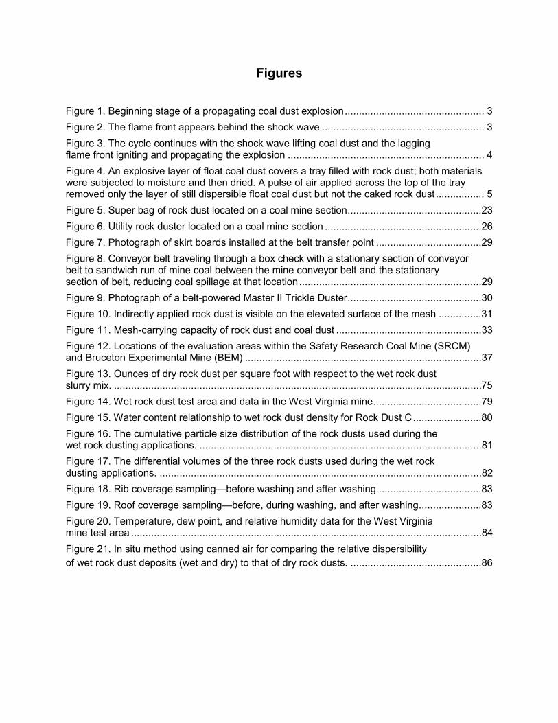
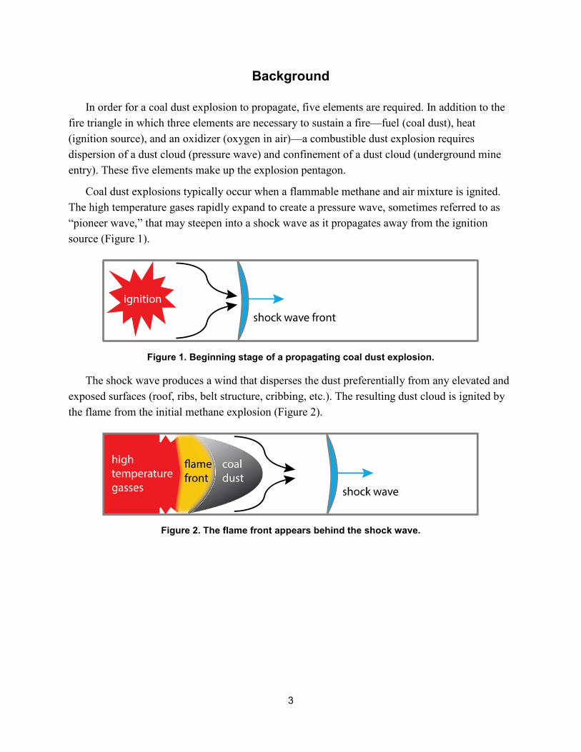
Coal dust explosions typically occur when a flammable methane and air mixture is ignited. The high temperature gases rapidly expand to create a pressure wave, sometimes referred to as “pioneer wave,” that may steepen into a shock wave as it propagates away from the ignition source (Figure 1).
Figure 1. Beginning stage of a propagating coal dust explosion.
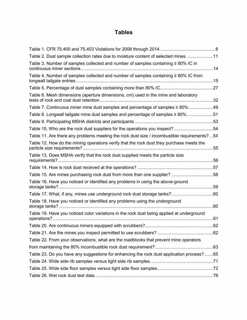
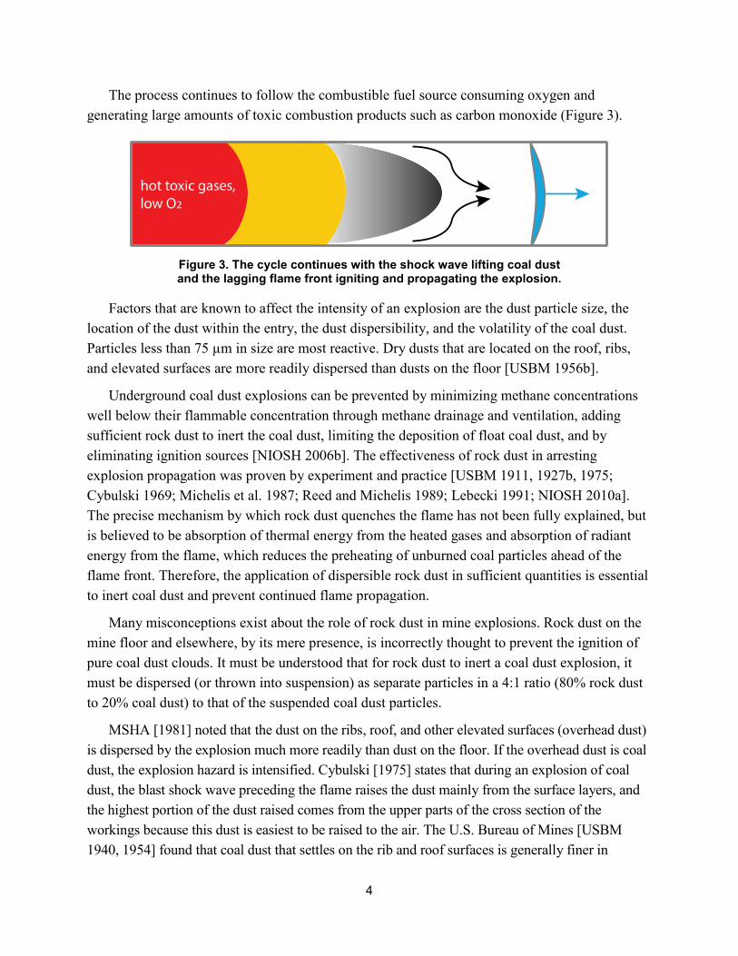
The shock wave produces a wind that disperses the dust preferentially from any elevated and exposed surfaces (roof, ribs, belt structure, cribbing, etc.). The resulting dust cloud is ignited by the flame from the initial methane explosion (Figure 2).
Figure 2. The flame front appears behind the shock wave.
4
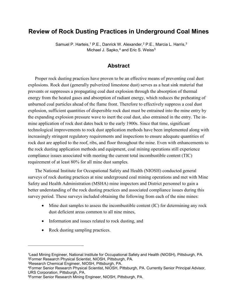
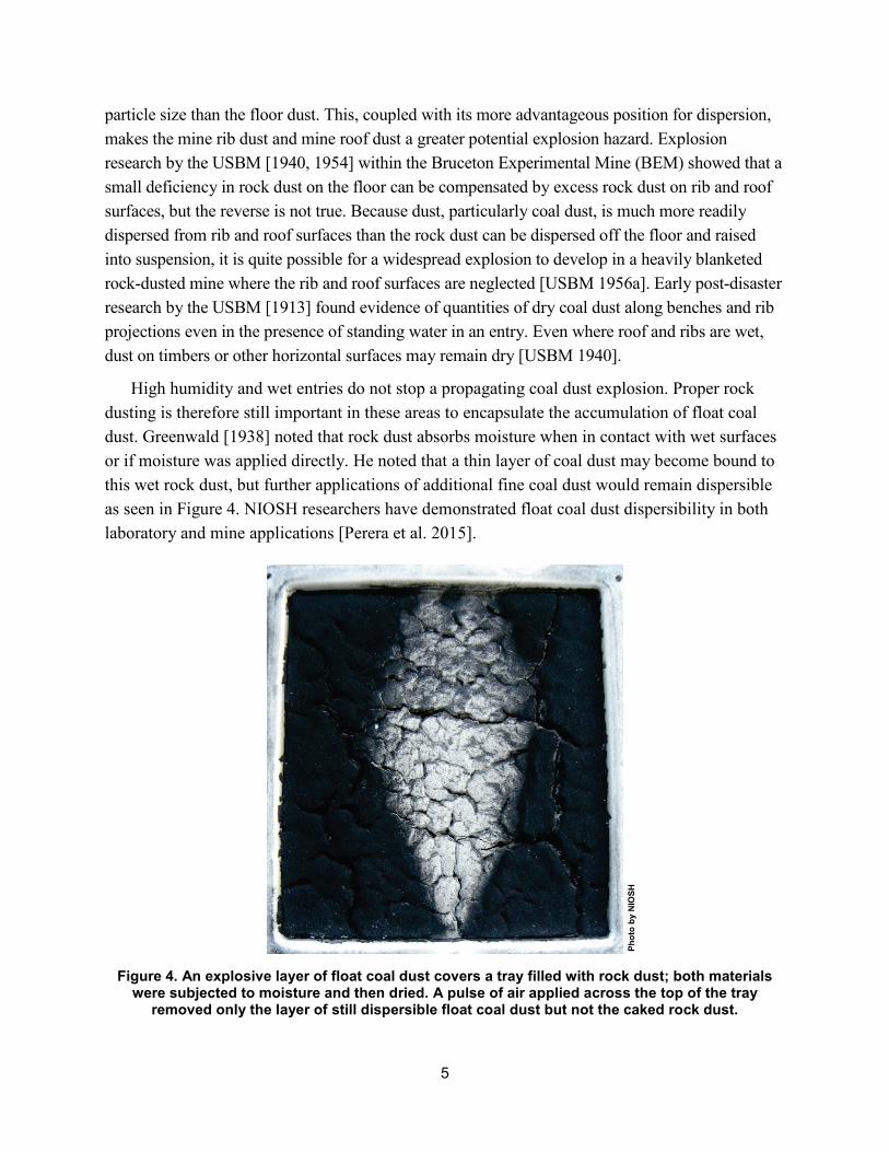
The process continues to follow the combustible fuel source consuming oxygen and generating large amounts of toxic combustion products such as carbon monoxide (Figure 3).
Figure 3. The cycle continues with the shock wave lifting coal dust and the lagging flame front igniting and propagating the explosion.
Factors that are known to affect the intensity of an explosion are the dust particle size, the location of the dust within the entry, the dust dispersibility, and the volatility of the coal dust. Particles less than 75 µm in size are most reactive. Dry dusts that are located on the roof, ribs, and elevated surfaces are more readily dispersed than dusts on the floor [USBM 1956b].
Underground coal dust explosions can be prevented by minimizing methane concentrations well below their flammable concentration through methane drainage and ventilation, adding sufficient rock dust to inert the coal dust, limiting the deposition of float coal dust, and by eliminating ignition sources [NIOSH 2006b]. The effectiveness of rock dust in arresting explosion propagation was proven by experiment and practice [USBM 1911, 1927b, 1975; Cybulski 1969; Michelis et al. 1987; Reed and Michelis 1989; Lebecki 1991; NIOSH 2010a]. The precise mechanism by which rock dust quenches the flame has not been fully explained, but is believed to be absorption of thermal energy from the heated gases and absorption of radiant energy from the flame, which reduces the preheating of unburned coal particles ahead of the flame front. Therefore, the application of dispersible rock dust in sufficient quantities is essential to inert coal dust and prevent continued flame propagation.
Many misconceptions exist about the role of rock dust in mine explosions. Rock dust on the mine floor and elsewhere, by its mere presence, is incorrectly thought to prevent the ignition of pure coal dust clouds. It must be understood that for rock dust to inert a coal dust explosion, it must be dispersed (or thrown into suspension) as separate particles in a 4:1 ratio (80% rock dust to 20% coal dust) to that of the suspended coal dust particles.
MSHA [1981] noted that the dust on the ribs, roof, and other elevated surfaces (overhead dust) is dispersed by the explosion much more readily than dust on the floor. If the overhead dust is coal dust, the explosion hazard is intensified. Cybulski [1975] states that during an explosion of coal dust, the blast shock wave preceding the flame raises the dust mainly from the surface layers, and the highest portion of the dust raised comes from the upper parts of the cross section of the workings because this dust is easiest to be raised to the air. The U.S. Bureau of Mines [USBM 1940, 1954] found that coal dust that settles on the rib and roof surfaces is generally finer in
5
particle size than the floor dust. This, coupled with its more advantageous position for dispersion, makes the mine rib dust and mine roof dust a greater potential explosion hazard. Explosion research by the USBM [1940, 1954] within the Bruceton Experimental Mine (BEM) showed that a small deficiency in rock dust on the floor can be compensated by excess rock dust on rib and roof surfaces, but the reverse is not true. Because dust, particularly coal dust, is much more readily dispersed from rib and roof surfaces than the rock dust can be dispersed off the floor and raised into suspension, it is quite possible for a widespread explosion to develop in a heavily blanketed rock-dusted mine where the rib and roof surfaces are neglected [USBM 1956a]. Early post-disaster research by the USBM [1913] found evidence of quantities of dry coal dust along benches and rib projections even in the presence of standing water in an entry. Even where roof and ribs are wet, dust on timbers or other horizontal surfaces may remain dry [USBM 1940].
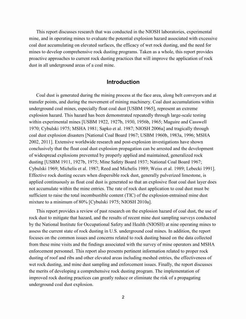
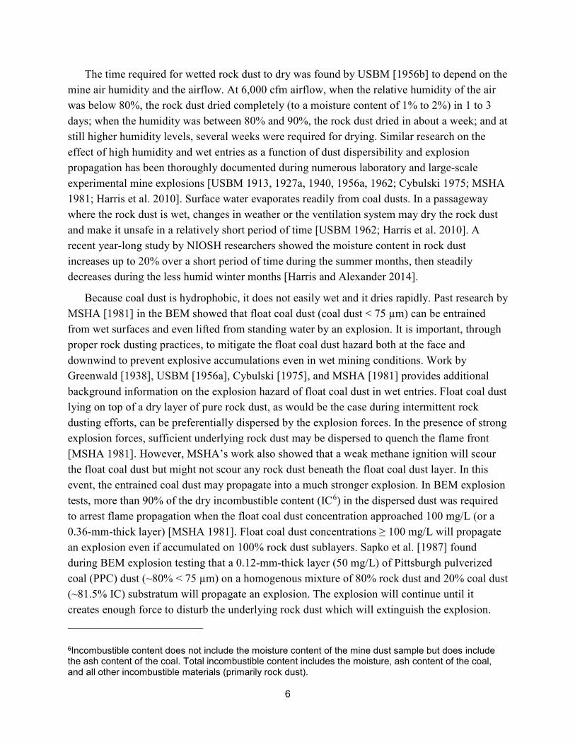
High humidity and wet entries do not stop a propagating coal dust explosion. Proper rock dusting is therefore still important in these areas to encapsulate the accumulation of float coal dust. Greenwald [1938] noted that rock dust absorbs moisture when in contact with wet surfaces or if moisture was applied directly. He noted that a thin layer of coal dust may become bound to this wet rock dust, but further applications of additional fine coal dust would remain dispersible as seen in Figure 4. NIOSH researchers have demonstrated float coal dust dispersibility in both laboratory and mine applications [Perera et al. 2015].
Figure 4. An explosive layer of float coal dust covers a tray filled with rock dust; both materials were subjected to moisture and then dried. A pulse of air applied across the top of the tray
removed only the layer of still dispersible float coal dust but not the caked rock dust.
Phot
o by
NIO
SH
6
The time required for wetted rock dust to dry was found by USBM [1956b] to depend on the mine air humidity and the airflow. At 6,000 cfm airflow, when the relative humidity of the air was below 80%, the rock dust dried completely (to a moisture content of 1% to 2%) in 1 to 3 days; when the humidity was between 80% and 90%, the rock dust dried in about a week; and at still higher humidity levels, several weeks were required for drying. Similar research on the effect of high humidity and wet entries as a function of dust dispersibility and explosion propagation has been thoroughly documented during numerous laboratory and large-scale experimental mine explosions [USBM 1913, 1927a, 1940, 1956a, 1962; Cybulski 1975; MSHA 1981; Harris et al. 2010]. Surface water evaporates readily from coal dusts. In a passageway where the rock dust is wet, changes in weather or the ventilation system may dry the rock dust and make it unsafe in a relatively short period of time [USBM 1962; Harris et al. 2010]. A recent year-long study by NIOSH researchers showed the moisture content in rock dust increases up to 20% over a short period of time during the summer months, then steadily decreases during the less humid winter months [Harris and Alexander 2014].
Because coal dust is hydrophobic, it does not easily wet and it dries rapidly. Past research by MSHA [1981] in the BEM showed that float coal dust (coal dust < 75 µm) can be entrained from wet surfaces and even lifted from standing water by an explosion. It is important, through proper rock dusting practices, to mitigate the float coal dust hazard both at the face and downwind to prevent explosive accumulations even in wet mining conditions. Work by Greenwald [1938], USBM [1956a], Cybulski [1975], and MSHA [1981] provides additional background information on the explosion hazard of float coal dust in wet entries. Float coal dust lying on top of a dry layer of pure rock dust, as would be the case during intermittent rock dusting efforts, can be preferentially dispersed by the explosion forces. In the presence of strong explosion forces, sufficient underlying rock dust may be dispersed to quench the flame front [MSHA 1981]. However, MSHA’s work also showed that a weak methane ignition will scour the float coal dust but might not scour any rock dust beneath the float coal dust layer. In this event, the entrained coal dust may propagate into a much stronger explosion. In BEM explosion tests, more than 90% of the dry incombustible content (IC6)
6Incombustible content does not include the moisture content of the mine dust sample but does include the ash content of the coal. Total incombustible content includes the moisture, ash content of the coal, and all other incombustible materials (primarily rock dust).
in the dispersed dust was required to arrest flame propagation when the float coal dust concentration approached 100 mg/L (or a 0.36-mm-thick layer) [MSHA 1981]. Float coal dust concentrations ≥ 100 mg/L will propagate an explosion even if accumulated on 100% rock dust sublayers. Sapko et al. [1987] found during BEM explosion testing that a 0.12-mm-thick layer (50 mg/L) of Pittsburgh pulverized coal (PPC) dust (~80% < 75 µm) on a homogenous mixture of 80% rock dust and 20% coal dust (~81.5% IC) substratum will propagate an explosion. The explosion will continue until it creates enough force to disturb the underlying rock dust which will extinguish the explosion.
7
Their research also found that concentrations of roof dust (coal dust on elevated surfaces) greater than 10% of the nominal float coal dust loading throughout the entry presents an elevated explosion hazard.
Research and post-explosion investigations have shown that rock dust that meets the specifications of 30 CFR Part 75, Mandatory Safety Standards, Underground Coal Mines, is generally effective at inerting coal dust if applied in sufficient quantity on all surfaces within the mine entry. It must also be able to be dispersed into separate particles during the mine explosion so as to result in a dust mixture with a minimum total incombustible content (TIC) of 80%. To achieve this level of coal dust explosion protection, mine operators should be proactive in their rock dusting operations, including performing frequent assessments of their mine dust to ensure dispersibility and that proper incombustible levels are maintained at all times.
Table 1 lists the total 30 CFR 75.400 and 75.403 violations for all underground coal mines for the years 2008 through 2014. In particular, it provides the number of violations per year and associated rankings for the accumulations of combustible materials (30 CFR 75.400) and the maintenance of incombustible content of rock dust (30 CFR 75.403). The number of violations listed per year in this table reflects two years prior to and three years after the regulatory revision to 30 CFR 75.403 (≥ 80% TIC requirement for all underground areas) made in 2010 [MSHA 2010]. Since the regulatory change to 30 CFR 75.403, the number of violations increased in ranking from 12th in 2010 to 3rd in 2014. Part of this increase can also be attributed to a better assessment of the explosibility hazard. The mine dust sampling protocol was modified in 2013. Changes include gathering the top 1/8 in of dust from the floor rather than 1-in deep, the ability to maintain the dust collected from the roof and rib separate from the floor rather than a collective combined band sample, and collecting the samples at random locations rather than at every 500 ft of new development [MSHA 2013b, c, d]. However, 30 CFR 75.400 violations remained consistent throughout the seven-year period and were ranked first for all years.
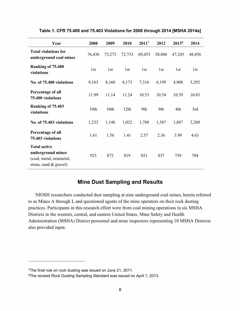
8
Table 1. CFR 75.400 and 75.403 Violations for 2008 through 2014 [MSHA 2014a]
Year 2008 2009 2010 20117 2012 20138 2014
Total violations for underground coal mines
76,430 73,273 72,733 69,453 58,806 47,245 48,856
Ranking of 75.400 violations
1st 1st 1st 1st 1st 1st 1st
No. of 75.400 violations 9,163 8,160 8,173 7,316 6,199 4,908 5,292
Percentage of all 75.400 violations
11.99 11.14 11.24 10.53 10.54 10.39 10.83
Ranking of 75.403 violations
10th 10th 12th 9th 9th 4th 3rd
No. of 75.403 violations 1,232 1,146 1,022 1,788 1,387 1,887 2,260
Percentage of all 75.403 violations
1.61 1.56 1.41 2.57 2.36 3.99 4.63
Total active underground mines (coal, metal, nonmetal, stone, sand & gravel)
925 872 819 851 837 759 704
7The final rule on rock dusting was issued on June 21, 2011. 8The revised Rock Dusting Sampling Standard was issued on April 1, 2013.
Mine Dust Sampling and Results
NIOSH researchers conducted dust sampling at nine underground coal mines, herein referred to as Mines A through I, and questioned agents of the mine operators on their rock dusting practices. Participants in this research effort were from coal mining operations in six MSHA Districts in the western, central, and eastern United States. Mine Safety and Health Administration (MSHA) District personnel and mine inspectors representing 10 MSHA Districts also provided input.
9
Rock Dusting Practices at the Participating Mines
Before the sampling study was conducted at each of the nine mines, NIOSH researchers met separately with representatives of each mine to discuss the rock dusting practices at their operations. Items discussed included methods and procedures for applying rock dust, rock dusting schedules, handling rock dust, how the determination is made that an area needs to be rock dusted, and the use of the Coal Dust Explosibility Meter (CDEM) [NIOSH 2012] to monitor the efficiency of rock dusting applications. The following is the information that was provided to NIOSH researchers by mine personnel at the time of NIOSH’s visits.
• Mine A. This mine follows a routine schedule for rock dusting in outby areas and belt entries. The mine did not specify how often it rock dusts the outby areas but stated that the mainline haulage was rock dusted every day. Visual inspections determine when rock dusting is required.
• Mine B. This mine applies wet rock dust on shift, followed up with dry dust using a bantam or sling duster. The mine relies on company mine examiners to note areas that are in need of rock dusting. The mine manager makes the decision for back entries to be rock dusted based on the information from the mine examiners. Visual inspections determine when rock dusting is required.
• Mine C. This mine does not have a formal rock dusting plan. Bulk dusting outby is routinely performed (no schedule provided) and every section move is followed up with bulk dusting ~500 to 800 ft (152 to 244 m) from the face. In the face area, dusting is performed with trickle and sling dusters. The longwall tailgate is dusted with a rock duster located at the headgate with a hose to the tailgate entry. Rock dusting is performed while coal is being produced, and compliance is monitored through visual inspection by mine examiners.
• Mine D. This mine did not provide NIOSH researchers with rock dusting practices information.
• Mine E. This mine applies 15 to 25 reinforced bags of rock dust in all three entries and crosscuts of the longwall development panels each time the developing section advances. These reinforced bags (i.e. super sacks) have a weight capacity of 1,000 to 3,000 lb (454 to 1,361 kg). The mine floor is covered with calcium chloride and then wetted down to harden and conglomerate the mine dust on the mine floor. The dust on the mine floor is not sampled as long as it stays damp; but if it dries out, the floor dust can be out of compliance. Each shift is given a section of underground belt to maintain. When required, the conveyor belts are rock dusted on weekends or spot dusted on shift. Visual observations determine when additional rock dusting is required.
10
• Mine F. This mine applies rock dust by hand on the ribs in the face area and follows up with additional rock dust from the scoop flinger duster at the end of each shift. Fifty-lb (~23-kg) bags of rock dust are exclusively used because super sacks are too large to handle in the low seam height. Conveyor belts are dusted by a narrow duster pulled by a two-person cart. A belt-driven, blower-powered rock duster applies rock dust when the conveyor belt is running. Travel ways are rock dusted occasionally during off shifts to allow the dust to migrate with the ventilation air and not interfere with production personnel. Visual observations are used to determine when rock dusting is required.
• Mine G. This mine applies rock dust on second or afternoon shifts because there is less traffic in the mine. Conveyor belts are rock dusted on a rotating basis, but the frequency was not stated. Sections are hand-dusted at the end of every shift. Flinger dusters distribute rock dust, and trickle dusters on the sections and at belt heads are used to control dust. The ribs and floor are hand-dusted during production within 40 ft (12 m) of the face, and blanket dusting is done on the midnight shift. Mine G is not permitted to have dust in the air where miners are working. Outby areas are dusted during the afternoon shift. The average amount of rock dust applied to each continuous miner super section is 25 short tons (23 metric tons) per week. The mine uses, on average, 80 short tons (73 metric tons) of rock dust per week. A CDEM is used to determine areas that need rock dusting.
• Mine H. This mine follows a routine schedule for applying rock dust in outby areas. The off shift (idle period) group does the intake rock dusting. Belt lines and returns are rock dusted on an ongoing basis. The rock dust teams complete reports that provide information to the next team as to where to continue rock dusting. Visual observations are used to determine when rock dusting is required. The longwall operates a rock duster at longwall shield no. 146, and there are a total of 150 shields on the face. A second rock duster is maintained near the belt tailpiece. Wet rock dust is applied in the face areas of the continuous miner sections to outby the section power center. Visual examinations are used to determine areas that need rock dusting.
• Mine I. This mine conducts hand dusting in the face areas during production shifts and routinely does outby rock dusting on Sundays. Depending on the mine conditions, additional employees may be scheduled to assist with rock dusting. Sections are rock dusted on the midnight shift using a slinger duster, and return entries are dusted more often than other entries. Visual observations are used to determine areas that need rock dusting.
Although certain aspects of a routine schedule for rock dusting were in place at these operations, none of the participating mines produced a written plan or document detailing rock dusting procedures. Visual observations were used to determine areas that need rock dusting in eight out of nine mines.
11
Sampling Locations
The nine mines participating in the study varied in size, depth, and seam. There were 266 planned dust sampling locations identified. Only 131 locations were dry enough to sample using a bristle brush and passing the collected mine dust through a 10 mesh sieve. The samples were collected during the following time periods:
• March – Mine D
• May – Mines C and G
• July – Mine B
• August – Mine H
• September – Mines A and I
• March – Mines E and F
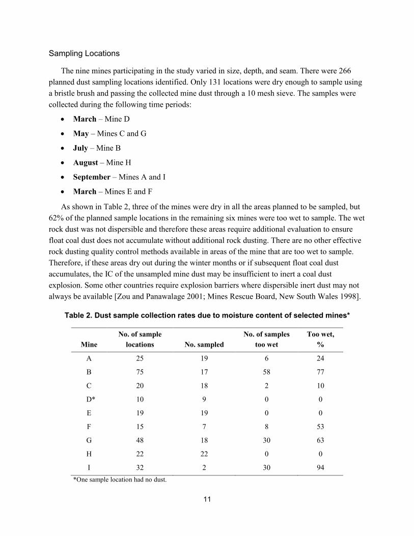
As shown in Table 2, three of the mines were dry in all the areas planned to be sampled, but 62% of the planned sample locations in the remaining six mines were too wet to sample. The wet rock dust was not dispersible and therefore these areas require additional evaluation to ensure float coal dust does not accumulate without additional rock dusting. There are no other effective rock dusting quality control methods available in areas of the mine that are too wet to sample. Therefore, if these areas dry out during the winter months or if subsequent float coal dust accumulates, the IC of the unsampled mine dust may be insufficient to inert a coal dust explosion. Some other countries require explosion barriers where dispersible inert dust may not always be available [Zou and Panawalage 2001; Mines Rescue Board, New South Wales 1998].
Table 2. Dust sample collection rates due to moisture content of selected mines*
*One sample location had no dust.
Mine No. of sample
locations No. sampled No. of samples
too wet Too wet,
%
A 25 19 6 24
B 75 17 58 77
C 20 18 2 10
D* 10 9 0 0
E 19 19 0 0
F 15 7 8 53
G 48 18 30 63
H 22 22 0 0
I 32 2 30 94
12
As a means of determining the effectiveness of the rock dusting practices for Mines A–I, dust samples were collected from the mine floor, ribs, roof, conveyor belt structure, cribs, pipes on the mine floor, and sampling pans placed on the mine floor (for sampling protocol used in this research, see Harris et al. 2014). The number of samples obtained from each operation with an IC of 80% or greater was compared to the total number of samples taken. The mine was then assessed based on the percentage of mine dust samples ≥ 80% IC. For example, if 20 mine dust samples were gathered and 15 of those mine dust samples indicated 80% IC or greater, the mine would receive a 75% compliance rating.
Information gathered for each operation included:
• IC distribution and corresponding number of samples
• Areas of the mine sampled
• Number of samples obtained
• Number of samples ≥ 80% IC
• Percentage of samples ≥ 80% IC
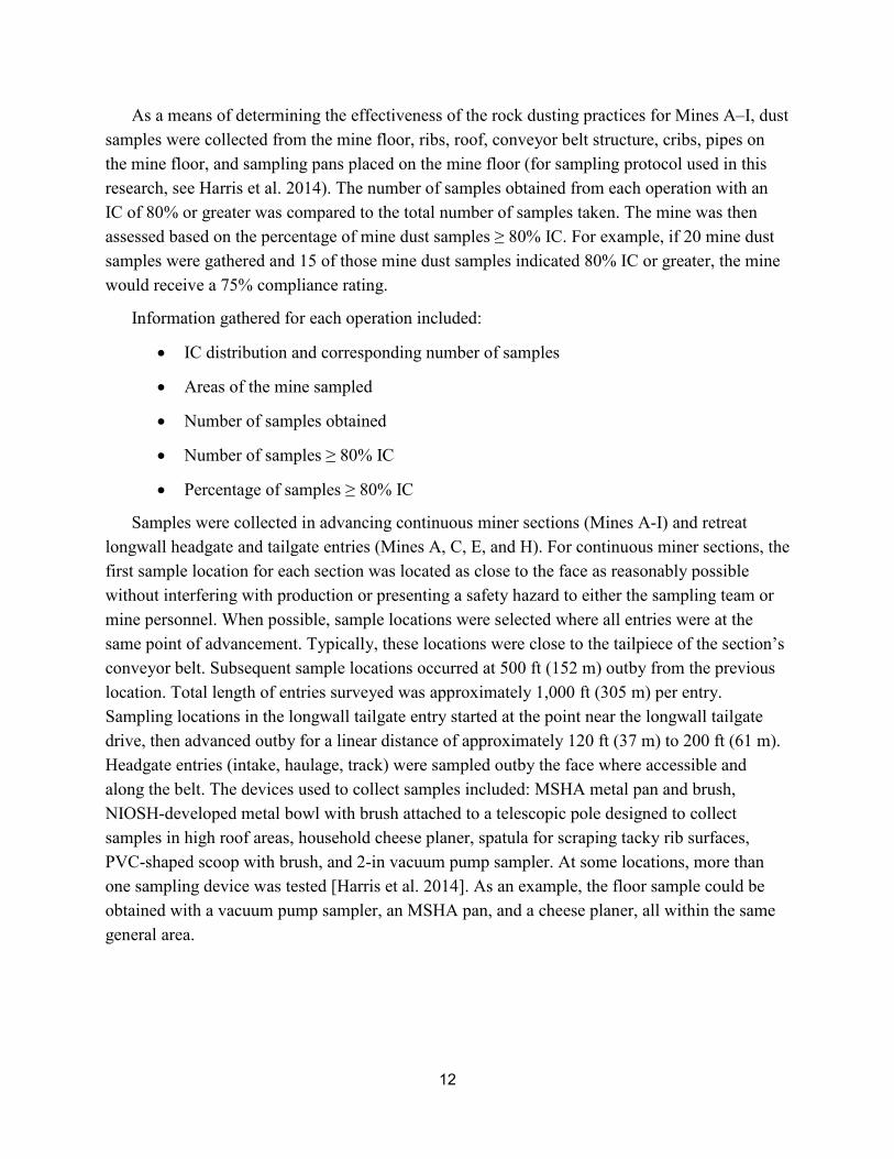
Samples were collected in advancing continuous miner sections (Mines A-I) and retreat longwall headgate and tailgate entries (Mines A, C, E, and H). For continuous miner sections, the first sample location for each section was located as close to the face as reasonably possible without interfering with production or presenting a safety hazard to either the sampling team or mine personnel. When possible, sample locations were selected where all entries were at the same point of advancement. Typically, these locations were close to the tailpiece of the section’s conveyor belt. Subsequent sample locations occurred at 500 ft (152 m) outby from the previous location. Total length of entries surveyed was approximately 1,000 ft (305 m) per entry. Sampling locations in the longwall tailgate entry started at the point near the longwall tailgate drive, then advanced outby for a linear distance of approximately 120 ft (37 m) to 200 ft (61 m). Headgate entries (intake, haulage, track) were sampled outby the face where accessible and along the belt. The devices used to collect samples included: MSHA metal pan and brush, NIOSH-developed metal bowl with brush attached to a telescopic pole designed to collect samples in high roof areas, household cheese planer, spatula for scraping tacky rib surfaces, PVC-shaped scoop with brush, and 2-in vacuum pump sampler. At some locations, more than one sampling device was tested [Harris et al. 2014]. As an example, the floor sample could be obtained with a vacuum pump sampler, an MSHA pan, and a cheese planer, all within the same general area.
13
Sampling Results from Continuous Miner Sections
For the mining operations participating in this research, the data clearly shows a wide range of percentage (%) IC results for samples collected in the continuous miner sections. Mine I had the lowest percentage (%) of samples ≥ 80% IC at 29%, with only 4 of 14 mine dust samples ≥ 80% IC. Mine G had the highest percentage (%) of samples ≥ 80% IC at 96%, with 55 of 57 mine dust samples ≥ 80% IC. The data also indicates mines apply rock dust better in some areas as compared to other areas of their mines. For example, Mine H had 100% of the mine roof dust samples ≥ 80% IC, but only 58% of the mine floor dust samples were ≥ 80% IC. Although it is known that overhead dust is more important than floor dust in whether an explosion propagates, the precise relationship between overhead and floor dust is not quantified and therefore dust samples from all areas of the mine are required to have at least 80% TIC. It is worth noting that the mine dust samples were representative of the conditions observed in the mine at that time and the samples were not combined into a single representative compliance sample. Also, floor sample pans permitted the collection of new coal dust generated during the ~48 hour sampling study and subsequent rock dust applications at two of the mines. Twenty-one floor pan samples were placed in Mine A, which does not use scrubbers on continuous miners. Sixteen or 76% of the samples were ≥ 80% IC. Mine B used scrubbers on the continuous miner sections and insufficient dust was deposited on the floor pans to collect a sample. These results are possible because: (1) wet rock dusting was used on the face which reduces the amount of airborne rock dust, (2) 77% of the areas were too wet to sample (see Table 1), which reduces the need to dry dust outby the feeder, and (3) scrubbers remove a large percentage of the float coal dust. In Mine H, the continuous miners were fitted with scrubbers. Fourteen floor pans were placed in Mine H, and the analysis indicated all 14 or 100% of the floor pan samples were ≥ 80% IC.9
9NIOSH sampling results refer to incombustible content (IC) which does not include the moisture content. MSHA mine dust surveys include the moisture content as well as the incombustible content and is considered as the total incombustible content (TIC). The NIOSH results would therefore be more conservative.
Although wet rock dusting was used, the mine was dry and additional dry dust was added outby in such quantities that rock dust was carried to the returns. Table 3 lists the number of samples collected and the number of samples containing ≥ 80% IC.
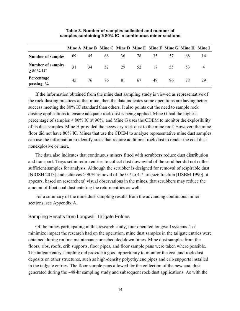
14
Table 3. Number of samples collected and number of samples containing ≥ 80% IC in continuous miner sections
Mine A Mine B Mine C Mine D Mine E Mine F Mine G Mine H Mine I
Number of samples 69 45 68 36 78 35 57 68 14
Number of samples ≥ 80% IC
31 34 52 29 52 17 55 53 4
Percentage passing, %
45 76 76 81 67 49 96 78 29
If the information obtained from the mine dust sampling study is viewed as representative of the rock dusting practices at that mine, then the data indicates some operations are having better success meeting the 80% IC standard than others. It also points out the need to sample rock dusting applications to ensure adequate rock dust is being applied. Mine G had the highest percentage of samples ≥ 80% IC at 96%, and Mine G uses the CDEM to monitor the explosibility of its dust samples. Mine H provided the necessary rock dust to the mine roof. However, the mine floor did not have 80% IC. Mines that use the CDEM to analyze representative mine dust samples can use the information to identify areas that require additional rock dust to render the coal dust nonexplosive or inert.
The data also indicates that continuous miners fitted with scrubbers reduce dust distribution and transport. Trays set in return entries to collect dust downwind of the scrubber did not collect sufficient samples for analysis. Although the scrubber is designed for removal of respirable dust [NIOSH 2013] and achieves > 90% removal of the 0.7 to 4.7 µm size fraction [USBM 1990], it appears, based on researchers’ visual observations in the mines, that scrubbers may reduce the amount of float coal dust entering the return entries as well.
For a summary of the mine dust sampling results from the advancing continuous miner sections, see Appendix A.
Sampling Results from Longwall Tailgate Entries
Of the mines participating in this research study, four operated longwall systems. To minimize impact the research had on the operation, mine dust samples in the tailgate entries were obtained during routine maintenance or scheduled down times. Mine dust samples from the floors, ribs, roofs, crib supports, floor pipes, and floor sample pans were taken where possible. The tailgate entry sampling did provide a good opportunity to monitor the coal and rock dust deposits on other structures, such as high-density polyethylene pipes and crib supports installed in the tailgate entries. The floor sample pans allowed for the collection of the new coal dust generated during the ~48-hr sampling study and subsequent rock dust applications. As with the
15
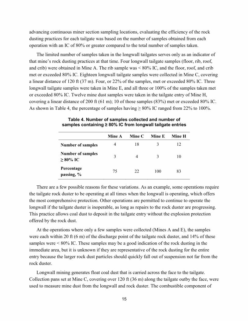
advancing continuous miner section sampling locations, evaluating the efficiency of the rock dusting practices for each tailgate was based on the number of samples obtained from each operation with an IC of 80% or greater compared to the total number of samples taken.
The limited number of samples taken in the longwall tailgates serves only as an indicator of that mine’s rock dusting practices at that time. Four longwall tailgate samples (floor, rib, roof, and crib) were obtained in Mine A. The rib sample was < 80% IC, and the floor, roof, and crib met or exceeded 80% IC. Eighteen longwall tailgate samples were collected in Mine C, covering a linear distance of 120 ft (37 m). Four, or 22% of the samples, met or exceeded 80% IC. Three longwall tailgate samples were taken in Mine E, and all three or 100% of the samples taken met or exceeded 80% IC. Twelve mine dust samples were taken in the tailgate entry of Mine H, covering a linear distance of 200 ft (61 m); 10 of those samples (83%) met or exceeded 80% IC. As shown in Table 4, the percentage of samples having ≥ 80% IC ranged from 22% to 100%.
Table 4. Number of samples collected and number of samples containing ≥ 80% IC from longwall tailgate entries
Mine A Mine C Mine E Mine H
Number of samples 4 18 3 12
Number of samples ≥ 80% IC
3 4 3 10
Percentage passing, %
75 22 100 83
There are a few possible reasons for these variations. As an example, some operations require the tailgate rock duster to be operating at all times when the longwall is operating, which offers the most comprehensive protection. Other operations are permitted to continue to operate the longwall if the tailgate duster is inoperable, as long as repairs to the rock duster are progressing. This practice allows coal dust to deposit in the tailgate entry without the explosion protection offered by the rock dust.
At the operations where only a few samples were collected (Mines A and E), the samples were each within 20 ft (6 m) of the discharge point of the tailgate rock duster, and 14% of these samples were < 80% IC. These samples may be a good indication of the rock dusting in the immediate area, but it is unknown if they are representative of the rock dusting for the entire entry because the larger rock dust particles should quickly fall out of suspension not far from the rock duster.
Longwall mining generates float coal dust that is carried across the face to the tailgate. Collection pans set at Mine C, covering over 120 ft (36 m) along the tailgate outby the face, were used to measure mine dust from the longwall and rock duster. The combustible component of
16
this mine dust was estimated to be between 0.02 to 0.05 lb (9.07 to 22.68 g) per raw ton mined over 5.5 shifts, which falls within the range of 0.01 to 0.18 lb (4.54 to 81.65 g) established by USBM [1965] for rock dust delivered outby the last open crosscut.
For a summary of the mine dust sampling results from the retreating longwall tailgate entries, see Appendix B.
Information Collected from Operators and Enforcement Personnel
All mines are required to develop a cleanup plan as 30 CFR 75.400-2 states: “A program for regular cleanup and removal of accumulations of coal and float coal dusts, loose coal, and other combustibles shall be established and maintained. Such program shall be available to the Secretary or authorized representative.”
These plans are not required to be submitted to or approved by MSHA but are used by MSHA inspectors to evaluate the effectiveness of the mine’s program. As the “Coal GIP Handbook Changes” states in the “Cleanup Program” section: “Inspectors shall evaluate the adequacy and effectiveness of the operator’s cleanup program continually by reviewing the enforcement history for regular cleanup and removal of accumulations of coal and float coal dust, loose coal, and other combustibles” [MSHA 2013d]. The mine’s written program must include details regarding how the operator will regularly control the accumulation of float coal dust, loose coal, and other combustibles. These details could involve the quantity, quality, schedule, and method for rock dust application in various locations.
MSHA indicates that mine operators should consider including the following elements in their written cleanup programs [MSHA 2013a]:
1. The regular cleanup methods for the removal of accumulations of coal and float coal dusts, loose coal, and other combustibles in all active workings or on diesel-powered and electrical equipment in these areas.
2. The equipment and methods used for applying rock dust to maintain 80% TIC as required by 75.403 and the methods to continuously apply rock dust to areas where coal dust is generated and float coal dust accumulates.
3. The means to evaluate the effectiveness of their cleanup program, such as a review of pre-shift examination records, rock dust usage, rock dust sampling results, and compliance history. Mine operators should place emphasis on critical areas such as longwall tailgates, belt transfer points, section returns, and bleeder entries.
In addition to collecting dust samples and noting the mine’s rock dusting methods, discussions were held with the mine operators and MSHA enforcement personnel to gather data related to rock dusting practices and associated documentation.
17
The data from nine mine operators provided some commonalities between operations, such as the use of similar rock dusting equipment, reliance on visual observations to determine the adequacy of rock dust applications, use of above-ground rock dust storage tanks, and increased use of flinger dusters in the face areas. Some operators received citations from MSHA inspectors due to violations for miners working downwind of the rock duster. Miners working downwind of the rock duster are being placed in an environment of reduced visibility which can lead to disorientation, accidents, injuries, and the increased exposure to mine dust.
The MSHA District Office personnel provided NIOSH with their insight into rock dusting practices. Discussions focused on the planned improvements to their Coal Mine Safety and Health, General Inspections Procedures Handbook, Chapter 5, Sampling Procedures [MSHA 2013b] and their efforts with the enforcement of regulations related to rock dusting practices to better address the shortcomings of some mining operations in maintaining at least an 80% TIC for their mine dust samples [30 CFR 75.403] while mitigating accumulations of combustible materials [30 CFR 75.400]. MSHA is focusing on the operator’s program through its recently revised sample collection methods and emphasis on the elimination of float coal dust [MSHA 2013c]. In order to accomplish this goal, MSHA announced that it is conducting more thorough quarterly reviews of cleanup programs and targeting areas with the highest coal dust explosion risks.
In 2013, MSHA’s coal dust sampling protocol was changed so that sample locations are based on areas of higher coal dust explosion risk or where the entry appearance indicates areas of lesser rock dust content than others. The past practice of sampling an advancing section every 500 ft (152 m) from the last sampled location has been revised to include both retreating and advancing working sections as well as from areas where coal dust is generated and more likely to accumulate, such as at transfer points along the belt lines. The sample locations are not limited to advancing sections as they have been in the past. Therefore, tailgate entries on a longwall section may be sampled upon longwall retreat. In areas that are too wet to collect a dust sample, adjacent areas are sampled or for large wet floor areas, the roof, ribs, and suspended items are sampled [MSHA 2013b, c].
In an effort to better detect explosible conditions, MSHA has modified the mine dust sampling method to allow mine inspectors to collect and keep mine dust from the roof and rib separate from the floor dust if there is a visual discrepancy between the two areas. Instead of brushing up to 1 in (25 mm) depth on the floor into the collection pan, only the upper layer ~1/8 in (3 mm) layer is collected. Dust from suspended items and structure is now to be included in the sample, whereas it was not before. Previously, if the roof was too high to reach, a sample was not collected. Now, the sample tool has an extended handle to reach previously inaccessible roof and ribs for mine dust collection [MSHA 2013b, c; Harris et al. 2014].
18
In the past, a citation was not issued unless 10% or more of the samples collected within a survey were noncompliant (samples were not in compliance with federal regulations). Currently, if only one sample is noncompliant, the whole survey is noncompliant and a citation is issued [MSHA 2013b, c].
MSHA is also focusing on cleanup programs and placing emphasis on critical areas such as longwall tailgates, belt transfer points, belt regulators, section returns, and bleeder entries. The agency is encouraging inspectors to review operators’ cleanup programs quarterly. In addition, MSHA is requiring the mine to address in writing the following items [MSHA 2013c]:
• Regular cleanup methods for the removal of accumulations of coal and float coal dusts, loose coal, and other combustibles in active workings, and on diesel-powered and electrical equipment.
• The methods used for applying rock dust to maintain 80% TIC as required by 30 CFR 75.403.
• The methods to continuously apply rock dust to areas where coal dust is generated and float coal dust accumulates.
• How mine operators will evaluate the effectiveness of their cleanup programs—such as the review of examination records, rock dust usage, rock dust sampling results, and compliance history.
The information that NIOSH researchers gathered from MSHA mine inspectors provided additional insight into rock dusting practices from the enforcement perspective. The discussions focused on obtaining additional information on rock dusting practices that MSHA inspectors witness every day in the field. A total of 35 inspectors representing 10 Districts participated in this survey. Each inspector was asked to complete a written survey comprised of 14 questions. Afterwards, open discussions were conducted by NIOSH with the group of MSHA inspectors. Following are the pertinent data results from the survey responses and subsequent discussions:
• Twenty-two of the 35 inspectors indicated that mine operators had no problems in meeting the rock dust size requirements specified in 30 CFR 75.2 or in meeting or exceeding the 80% TIC requirement for mine dust as specified in 30 CFR 75.403. This was a surprising outcome as mines are still experiencing problems in maintaining adequate mine dust incombustible levels as based on the information obtained from the MSHA sampling database and the recent limited NIOSH mine dust sampling results.
19
However, MSHA data indicates that from 2008 to 2014, the number of 30 CFR 75.403 (total incombustible) violations increased from 1,256 to 2,383. This increase in the number of violations did not appear to be influenced by the change of the revised sampling policy that was implemented in April 2013. This revised sampling policy states:
“However, where there are multiple violations of the same standard which are observed in the course of an inspection and which are all related to the same piece of equipment or to the same area of the mine, such multiple violations should be treated as one violation, and one citation should be issued” [MSHA 1996].
Prior to April 2013, a violation would be issued if more than 10% of the samples taken were noncompliant. Although the number of 30 CFR 75.400 violations (accumulation of combustible materials) decreased from 9,388 in 2008 to 5,495 in 2014, this continues to be the highest ranked violation. Over the same time period, 30 CFR 75.403 violations have moved from a ranking of 10th in 2008 to 3rd in 2014.
When asked if the mines they inspect have continuous miners with scrubbers, 94% of the MSHA journeymen inspectors responded “yes.” Operators who do not diligently maintain scrubber systems as designed and approved can face losing their deep cut mining plans [Carpenter 2012]. Also, the MSHA Handbook Series, Handbook Number PH89-V-1(27) states: “elimination of deep cut systems may be required to help ensure miners are protected against respirable dust exposure” [MSHA 2016].
MSHA inspectors also provided their insights on the roadblocks that prevent operators from maintaining the 80% TIC requirement and their ideas for enhancing the rock dusting application process. The following is a partial list of the inspectors’ observations, separated into roadblocks and enhancements:
Roadblocks • Failing to adequately clean uneven mine floor (i.e., bottom) prior to applying rock dust.
• Applying rock dust in the intake airway while outby equipment is traveling through previously rock dusted areas.
• Not applying adequate rock dust as the section advances.
• Waiting for rock-dusted areas to turn dark before applying rock dust.
• Not following good rock dusting practices.
• Allowing poor cleanup prior to dusting.
20
Enhancements • Implementing continuous rock dusting during the mining process.
• Following good scooping procedures.
• Maintaining a specific rock dusting cycle.
• Making rock dusting a priority.
• Using machine-mounted rock dusters on roof bolting machines for rock dusting face areas.
• Increasing use of continuous dusters.
• Stressing better cleanup on sections when advancing.
• Powering down trickle dusters where miners work and travel while workers are inby.
A complete listing of the questions and responses can be found in Appendix C.
Rock Dusting Practices and Considerations
The current practice of outby rock dusting at many U.S. underground coal mines is to deploy rock dust pneumatically from bulk tanks throughout most of the mine entries and supplement this application with the use of rock dusters in the return airways. This is similar to the standard practice established by the USBM [1960a]. Bulk tanks may be track-mounted, rubber-tired, or stationary. Rock dusting efforts are primarily focused on haulage ways, conveyor belts, and return entries because fine coal dust particles are deposited in these entries. In some mines, dusters are used to continuously release rock dust into the return air of active development and production sections or upwind of belt transfer and air locks. Production rock dusting within 40 ft (12 m) of the face is completed using several methods, including hand spreading from bags, bolter dusting as the roof bolting machine is withdrawn from the working face, dusting within 40 ft of the working faces with dusters mounted on the loading machine, end-of-shift flinger dusting from scoop buckets, or wet dusting during the shift. In other mines, the rock dusting is conducted primarily during nonproduction periods. For a list of commonly used equipment to apply rock dust, see Appendix D. For information on rock dust shipping, storage, and distribution, see Appendix E.
Of the nine participating mines in this NIOSH study, seven of them discharge rock dust from a surface bin through a borehole into the underground mine. Two mines have the ability to store bulk rock dust in a dry location underground. One of them uses a series of pressure tanks powered by large-capacity compressors to transfer rock dust pneumatically from one pressure tank to another. These pressurized tanks are spaced 3,000 ft (914 m) apart and can support branch lines from the main pipelines at convenient locations for rock dusting areas in between
21
pressure tanks [Dezeeuw 2011]. The other mine installed a 15-short ton (14-metric ton) rock dust surge bin underground. This enables the operator to store and discharge bulk rock dust into receiving vessels underground as needed. When the surge bin is empty, it is refilled from the surface rock dust tank. The benefit of having a rock dust surge bin underground is that it can provide quick access to dry rock dust. A miner responsible for rock dusting can position the rock duster adjacent to the surge bin, load the desired amount of rock dust from the surge bin, proceed to the area requiring rock dust, unload the rock dust as required, and return to the surge bin for the next load of rock dust. However, it is not advisable to store bulk rock dust underground for long periods of time because it absorbs moisture and becomes less dispersible and more difficult to handle.
Meeting Compliance and Dispensing Rock Dust
In addition to receiving certifications from the rock dust manufacturer or supplier verifying that the rock dust is in compliance, mine operators should also conduct frequent validation checks on the quality of their rock dusts to ensure that the rock dusts meet or exceed the specifications of 30 CFR 75.2.
The mine operator must rock dust as per 30 CFR 75.403:
“Where rock dust is required to be applied, it shall be distributed upon the top, floor, and sides of all underground areas of a coal mine and maintained in such quantities that the incombustible content of the combined coal dust, rock dust, and other dust shall be not less than 80 percent. Where methane is present in any ventilating current, the percent of incombustible content of such combined dust shall be increased 0.4 percent for each 0.1 percent of methane.”
At locations where mine dust is generated, intermittent rock dusting is not desirable because a potentially explosive layer of fine coal dust may accumulate between rock dusting applications.
The location and orientation of the rock dust discharge points should be considered when evaluating rock dusting practices. The discharge point should be oriented horizontally, close to the mine roof, and located near the center of the entry to maximize the rock dust coverage length. If the rock dust discharge is pointed upward, the rock dust will impact the mine roof and fall to the mine floor in a very short distance instead of transporting much longer distances down the mine entry. If the discharge is pointed in a downward angle, the rock dust will again deposit on the mine floor over a short path and provide little coverage to the rest of the entry.
The amount of airborne coal dust that is formed during a mining operation and the deposition behaviors of the coal and rock dust particles along an airway are not well known. Therefore, the frequency with which new rock dust should be dispersed or at least raked (mixing new coal dust accumulations into old rock dust deposits on the floor) is also not well understood. Some mine
22
operators may rock dust excessively in many areas of their mine and, thereby, incur unnecessary expense in material and labor, while others may rock dust too little and thereby increase the potential for a dust explosion and more frequent violations.
Mine operators should consider monitoring the percentage (%) IC of their dust throughout the mine on a frequent basis and not rely only on the visual observations or sampling results of the mine evaluators or MSHA inspectors. This can be accomplished by taking representative samples within the mine entries, then analyzing those samples. The traditional method of dust sample analyses involves a low temperature ashing (LTA) method where the sample is heated to drive off the moisture and combustible materials leaving only the IC [Montgomery 2005; NIOSH 2010a]. This method requires laboratory work with results taking days or weeks to receive. Another method that can be easily used by the mine operator involves the measurement of the explosibility of the representative mine dust sample using the CDEM [NIOSH 2012]. A properly calibrated CDEM provides an accurate and rapid measurement of the explosibility of the mine dust sample, allowing mine operators to immediately address any rock dust deficient areas of the mine.
The underground area surrounding the rock dust borehole should be kept in a neat and orderly condition. Excessive accumulations of rock dust can hinder or prevent the machine operator from accessing the borehole. At one operation, NIOSH researchers witnessed a machine maneuvering through 15 in (38 cm) of deep, loose rock dust to access the borehole. Loose rock dust also creates a potential tripping or stumbling hazard for mine workers.
The following sections discuss considerations that mine operators should be aware of when applying dry rock dust in advancing continuous miner sections, longwall sections, conveyor belt entries, and elevated surfaces. Wet rock dusting practices will then be discussed.
Advancing Continuous Miner Sections
Hand dusting or “chicken dusting,” as it is often referred, describes when a mine worker grabs handfuls of rock dust and flings it onto the roof, ribs, and floor. This method used to be the primary means for all mines in applying rock dust in the face areas and is still used by a few operations. Unless performed in a very conscientious manner, hand dusting generally does not result in adequate rock dust coverage and certainly does not produce a uniform distribution. One operator stated that the company was having difficulty getting rock dust to stick to the mine roof and ribs until the company procedure was changed to washing down the roof and ribs prior to rock dust application. As a result of this change, the percentage of rock dust samples not meeting the 80% minimum standard dropped considerably.
A more typical approach to the application of rock dust is the use of a machine-mounted rock duster. These machine dusters are becoming more common in the face area because of their ability to quickly provide heavier and more even rock dust coverage than can be accomplished by hand dusting. The latest trend is to apply rock dust on advancing sections with rock dusters
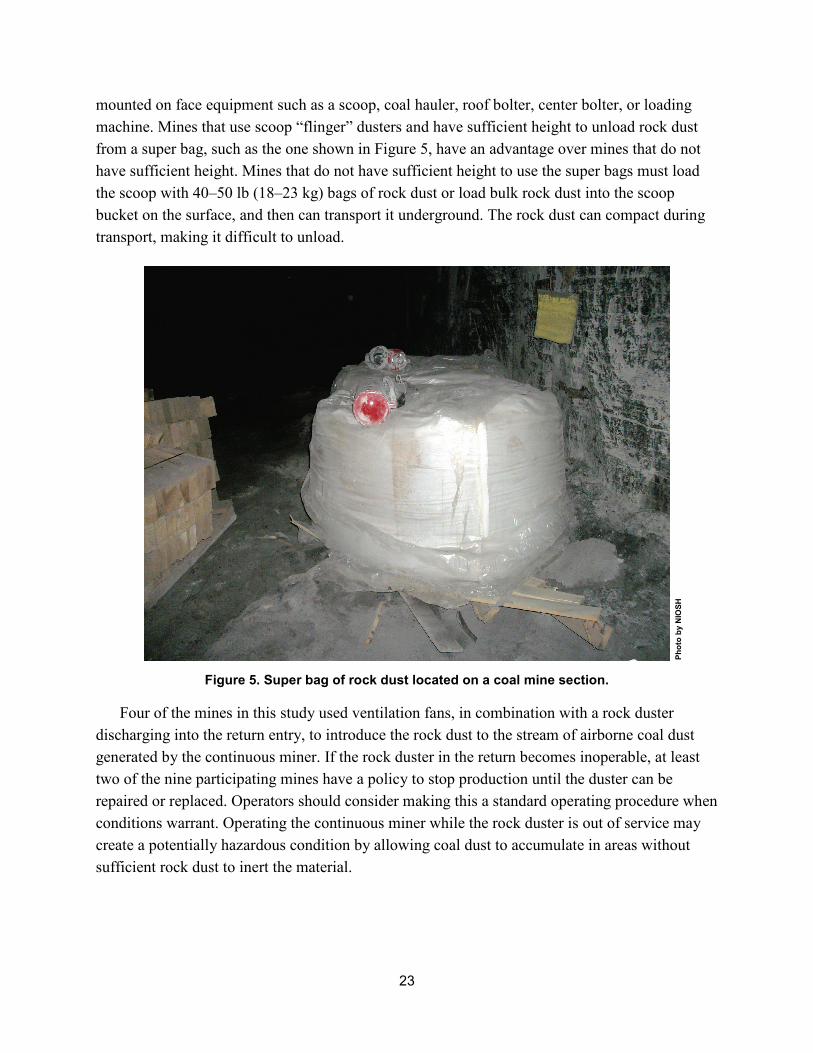
23
mounted on face equipment such as a scoop, coal hauler, roof bolter, center bolter, or loading machine. Mines that use scoop “flinger” dusters and have sufficient height to unload rock dust from a super bag, such as the one shown in Figure 5, have an advantage over mines that do not have sufficient height. Mines that do not have sufficient height to use the super bags must load the scoop with 40–50 lb (18–23 kg) bags of rock dust or load bulk rock dust into the scoop bucket on the surface, and then can transport it underground. The rock dust can compact during transport, making it difficult to unload.
Figure 5. Super bag of rock dust located on a coal mine section.
Four of the mines in this study used ventilation fans, in combination with a rock duster discharging into the return entry, to introduce the rock dust to the stream of airborne coal dust generated by the continuous miner. If the rock duster in the return becomes inoperable, at least two of the nine participating mines have a policy to stop production until the duster can be repaired or replaced. Operators should consider making this a standard operating procedure when conditions warrant. Operating the continuous miner while the rock duster is out of service may create a potentially hazardous condition by allowing coal dust to accumulate in areas without sufficient rock dust to inert the material.
Phot
o by
NIO
SH
24
The use of scrubbers on continuous miners to reduce the amount of mine dust generated should be considered where conditions permit. Flooded bed scrubbers capture dust-laden air from the cutting face, carry this air through ductwork on the continuous miner, and pass the air through a filter panel that is wetted with water sprays. As mine dust particles impact and travel through the filter panel, the particles mix with water droplets and are removed from the airstream by a mist eliminator. The cleaned air is discharged from the scrubber back into the mine environment [NIOSH 2010b]. In addition, where continuous miners are equipped with scrubbers, the scrubbers should be running while the continuous mining machine’s cutterhead is operating.
Sampling efforts over two-day periods to collect airborne dust that settled onto the floor collection trays resulted in little to no coal dust on the trays in the returns of sections using scrubbers. Referring to the discussion in the “Rock Dusting Practices at the Participating Mines” section of this report, collection pans on sections using scrubbers contained > 80% IC because of the high dust removal attained by the scrubbers and the corresponding low amount of float coal dust carried to the return. This illustrates the beneficial nature of scrubbers to remove most of the explosible coal dust from the return air.
At one surveyed mine, a shuttle car was observed using drag bars installed under the car. The intent was to use the drag bars to smooth out the shuttle car roadways. The drag bars also serve as a rake to minimize the effect of float coal dust accumulations by mixing mine dust with the underlying rock dust substratum. However, care must be taken to regularly sample the surface of these raked areas to ensure that the mine dust continues to be at least 80% TIC. In another operation, atomizing water sprays are used outby the feeder to reduce airborne dust on the section from rock dusting the belt on shift. Although this has not been evaluated by NIOSH, the use of water sprays has the potential to limit respirable airborne dust from entering the working areas [Reichardt 2014].
Longwall Section
On a typical longwall development section, the outside headgate entry farthest away from the belt entry becomes the tailgate entry for the next longwall panel. This entry is rock dusted to meet the 80% TIC requirement during its development, and additional rock dust is applied during the mining of the longwall panel. One mine operator, taking a proactive approach to rock dusting, placed an electrical powered rock duster in the future tailgate entry. As the longwall face retreats, the rock duster applies an additional layer of rock dust in the tailgate haul road. Some mines position bulk bag rock dust in an appropriate area for future use. Access to the headgate entry, at least for this operation, is much easier at this point in the mining cycle. When the longwall is moved to the next panel and begins operation, gaining access to the tailgate entry can be limited to entrance from the longwall face or near the longwall recovery or pullout area. However, only representative sampling can verify the actual % TIC.
25
A growing practice is the use of rock dusters positioned in the longwall headgate area that pneumatically transport rock dust through a 900–1,500 ft (275–450 m) long pipe across the longwall face to a discharge hose or manifold system in the tailgate. This is a desired approach to rock dusting the tailgate entry because the rock dust can be continuously applied during the longwall coal cutting operation. If rock dust is discharged in sufficient quantities, the rock dust will transport downwind mixing with the fugitive coal dust, thereby avoiding dangerous accumulations of float coal dust.
At one mine, typically fifteen 50-lb (~23-kg) bags of rock dust per shift were pneumatically transported across the face from a 20-hp (14.9-kw) rock duster at the headgate, which equates to 750 lb (340 kg) of rock dust or approximately 1.7 lb (0.8 kg) of rock dust per available operating minute (at 7.5 hours out of an 8-hr shift) or 0.06 lb (0.027 kg) of rock dust per raw ton mined. However, this amount of rock dust must be compared to the resulting percentage (%) IC in the tailgate entry. In this case, dust collected in the tailgate was 76.9% IC. An additional 150 lb (68 kg) of rock dust per shift (total 900 lb (408 kg)) is needed to reach 80% IC in the areas investigated, which equates to 2.0 lb (0.9 kg) rock dust per available operating minute or 0.07 lb (0.031 kg) of rock dust per raw ton mined.
The downside to this arrangement is that damp rock dust can clog the pipeline that extends from the rock duster to the tailgate. When clogs occur, the pipe must be cleaned out. Anticaking dispersible rock dust was found to flow at a faster rate through a trickle duster and may also improve fluidity for transport across the longwall face [IMERYS 2014]. The other option is to install the rock duster close to the tailgate entry and manually fill the duster with bagged rock dust. The discharge hose length is shorter and less likely to clog, but there is a risk that the rock duster hopper will empty while the longwall is operating, leading to float coal dust accumulations. Also, there is an increased risk of injuries to miners manually transporting bagged rock dust across the longwall face. Either one of these approaches to rock dusting the tailgate entry is acceptable if completed whenever the longwall is generating float coal dust.
Some operations prohibit operating the shearer if rock dust cannot be simultaneously discharged to the tailgate entry. Operators should consider making this an operating standard. If the shearer is permitted to continue operation while the rock duster is out of service, the float coal dust will continue to accumulate in the tailgate entry. In time this could allow a potential explosion hazard to be created.
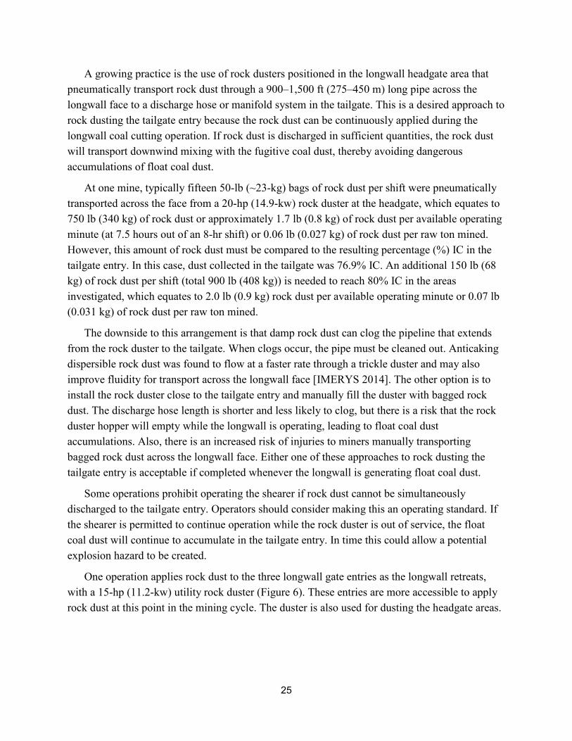
One operation applies rock dust to the three longwall gate entries as the longwall retreats, with a 15-hp (11.2-kw) utility rock duster (Figure 6). These entries are more accessible to apply rock dust at this point in the mining cycle. The duster is also used for dusting the headgate areas.
26
Phot
o by
NIO
SH
Figure 6. Utility rock duster located on a coal mine section.
Conveyor Belt Entries
Maintaining at least 80% TIC levels for the mine dust within belt conveyor entries presents many unique challenges for mine operators due to the large amounts of coal dust that are on the belt. This coal dust can become airborne due to belt movement and at transfer points. Accumulations of float coal dust on the belt structure, roof, ribs, and floor in the inherently limited space within these entries must be addressed.
The typical sampling protocol for nonbelt entries followed by the NIOSH researchers in this study included combining the samples from the left and right rib into one rib sample. However, in the belt conveyor entries, the rib sample from the tight side (also referred to as the “narrow” side) was kept separate from the rib sample on the wide or walkway side for analysis. Keeping the samples separate was necessary to determine if the samples from the wide side, which is easier to access, received enhanced rock dust coverage compared to the tight side of the belt entry. A total of 299 rib samples were obtained from the nine mines; 182 samples were taken from the rib on the wide side of the entry and 117 samples taken from the rib on the tight side of the entry. Twenty-three of the 182 wide side samples, or 13%, were less than 80% IC. Thirty-seven of the 117 tight side samples, or 32%, were less than 80% IC. Seventy-six mine floor samples were also obtained from the wide and tight side of the mine entry, 44 from the wide side and 32 from the tight side. Of the 44 wide side samples, 4 of the samples, or 9%, were less than 80% IC. Of the 32 tight side samples, 15 of the samples, or 47%, were less than 80% IC. Based on the data analyses of these samples, the trend indicates that less rock dust is being applied to
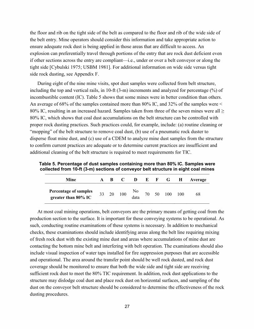
27
the floor and rib on the tight side of the belt as compared to the floor and rib of the wide side of the belt entry. Mine operators should consider this information and take appropriate action to ensure adequate rock dust is being applied in those areas that are difficult to access. An explosion can preferentially travel through portions of the entry that are rock dust deficient even if other sections across the entry are compliant—i.e., under or over a belt conveyor or along the tight side [Cybulski 1975; USBM 1981]. For additional information on wide side versus tight side rock dusting, see Appendix F.
During eight of the nine mine visits, spot dust samples were collected from belt structure, including the top and vertical rails, in 10-ft (3-m) increments and analyzed for percentage (%) of incombustible content (IC). Table 5 shows that some mines were in better condition than others. An average of 68% of the samples contained more than 80% IC, and 32% of the samples were < 80% IC, resulting in an increased hazard. Samples taken from three of the seven mines were all ≥ 80% IC, which shows that coal dust accumulations on the belt structure can be controlled with proper rock dusting practices. Such practices could, for example, include: (a) routine cleaning or “mopping” of the belt structure to remove coal dust, (b) use of a pneumatic rock duster to disperse float mine dust, and (c) use of a CDEM to analyze mine dust samples from the structure to confirm current practices are adequate or to determine current practices are insufficient and additional cleaning of the belt structure is required to meet requirements for TIC.
Table 5. Percentage of dust samples containing more than 80% IC. Samples were collected from 10-ft (3-m) sections of conveyor belt structure in eight coal mines
Mine A B C D E F G H Average
Percentage of samples greater than 80% IC
33 20 100 No data
70 50 100 100 68
At most coal mining operations, belt conveyors are the primary means of getting coal from the production section to the surface. It is important for these conveying systems to be operational. As such, conducting routine examinations of these systems is necessary. In addition to mechanical checks, these examinations should include identifying areas along the belt line requiring mixing of fresh rock dust with the existing mine dust and areas where accumulations of mine dust are contacting the bottom mine belt and interfering with belt operation. The examinations should also include visual inspection of water taps installed for fire suppression purposes that are accessible and operational. The area around the transfer point should be well rock dusted, and rock dust coverage should be monitored to ensure that both the wide side and tight side are receiving sufficient rock dust to meet the 80% TIC requirement. In addition, rock dust applications to the structure may dislodge coal dust and place rock dust on horizontal surfaces, and sampling of the dust on the conveyor belt structure should be considered to determine the effectiveness of the rock dusting procedures.
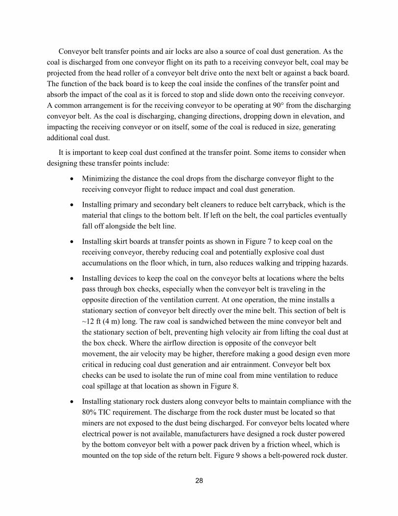
28
Conveyor belt transfer points and air locks are also a source of coal dust generation. As the coal is discharged from one conveyor flight on its path to a receiving conveyor belt, coal may be projected from the head roller of a conveyor belt drive onto the next belt or against a back board. The function of the back board is to keep the coal inside the confines of the transfer point and absorb the impact of the coal as it is forced to stop and slide down onto the receiving conveyor. A common arrangement is for the receiving conveyor to be operating at 90° from the discharging conveyor belt. As the coal is discharging, changing directions, dropping down in elevation, and impacting the receiving conveyor or on itself, some of the coal is reduced in size, generating additional coal dust.
It is important to keep coal dust confined at the transfer point. Some items to consider when designing these transfer points include:
• Minimizing the distance the coal drops from the discharge conveyor flight to the receiving conveyor flight to reduce impact and coal dust generation.
• Installing primary and secondary belt cleaners to reduce belt carryback, which is the material that clings to the bottom belt. If left on the belt, the coal particles eventually fall off alongside the belt line.
• Installing skirt boards at transfer points as shown in Figure 7 to keep coal on the receiving conveyor, thereby reducing coal and potentially explosive coal dust accumulations on the floor which, in turn, also reduces walking and tripping hazards.
• Installing devices to keep the coal on the conveyor belts at locations where the belts pass through box checks, especially when the conveyor belt is traveling in the opposite direction of the ventilation current. At one operation, the mine installs a stationary section of conveyor belt directly over the mine belt. This section of belt is ~12 ft (4 m) long. The raw coal is sandwiched between the mine conveyor belt and the stationary section of belt, preventing high velocity air from lifting the coal dust at the box check. Where the airflow direction is opposite of the conveyor belt movement, the air velocity may be higher, therefore making a good design even more critical in reducing coal dust generation and air entrainment. Conveyor belt box checks can be used to isolate the run of mine coal from mine ventilation to reduce coal spillage at that location as shown in Figure 8.
• Installing stationary rock dusters along conveyor belts to maintain compliance with the 80% TIC requirement. The discharge from the rock duster must be located so that miners are not exposed to the dust being discharged. For conveyor belts located where electrical power is not available, manufacturers have designed a rock duster powered by the bottom conveyor belt with a power pack driven by a friction wheel, which is mounted on the top side of the return belt. Figure 9 shows a belt-powered rock duster.
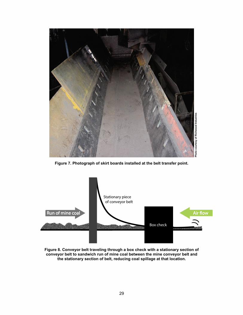
29
Phot
o co
urte
sy o
f Ric
hwoo
d In
dust
ries
Figure 7. Photograph of skirt boards installed at the belt transfer point.
Figure 8. Conveyor belt traveling through a box check with a stationary section of conveyor belt to sandwich run of mine coal between the mine conveyor belt and
the stationary section of belt, reducing coal spillage at that location.
Stationary piece of conveyor belt
Run of mine coal
Box check
30
Phot
o co
urte
sy o
f A. L
. Lee
Cor
pora
tion
Figure 9. Photograph of a belt-powered Master II Trickle Duster.
Rock Dusting Practices Related to Elevated Surfaces of a Mine
NIOSH researchers have conducted an assessment of the effect of elevated surfaces on rock dust distribution and the possibility of suspending float coal dust accumulations. The study focused primarily on ground control mesh, but the principles apply to any elevated surface. The safety benefits of installing mesh have been well recognized [Compton et al. 2007]; mesh is an excellent method of controlling roof and rib spalling. When proper rock dusting practices are followed, the mesh provides additional elevated, horizontal surfaces for rock dust to accumulate. Explosion research has shown that it is essential to apply sufficient quantities of rock dust to the rib, roof, and elevated surfaces [USBM 1954, 1981; Cybulski 1975]. Recent laboratory-scale testing demonstrated that some mesh products can hold more rock dust than others, providing more explosion protection. Likewise, and unless proper rock dusting practices are followed, some mesh products can hold sufficient quantities of float coal dust by themselves to propagate an explosion. The mesh surfaces have the capacity to hold more rock dust and coal dust as compared to bare roof and rib surfaces [Alexander and Chasko 2014].
The in-mine rock dust and coal dust application tests were conducted using three methods: (a) trickle dusting at a stationary location, (b) direct impingement onto the mesh as the rock duster moved down the entry, and (c) indirect impingement where the mesh was not directly hit with the rock dust discharge. The amount of dust that could deposit on the mesh was highly variable depending on the mesh flexibility, exit velocity, distance from the nozzle, and moisture conditions. Very little dust settled on the mesh when using the rock duster as a trickle duster; the dust was distributed down the entry primarily by the ventilation air as would be the case with
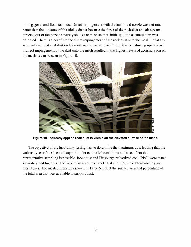
31
mining-generated float coal dust. Direct impingement with the hand-held nozzle was not much better than the outcome of the trickle duster because the force of the rock dust and air stream directed out of the nozzle severely shook the mesh so that, initially, little accumulation was observed. There is a benefit to the direct impingement of the rock dust onto the mesh in that any accumulated float coal dust on the mesh would be removed during the rock dusting operations. Indirect impingement of the dust onto the mesh resulted in the highest levels of accumulation on the mesh as can be seen in Figure 10.
Phot
o by
NIO
SH
Figure 10. Indirectly applied rock dust is visible on the elevated surface of the mesh.
The objective of the laboratory testing was to determine the maximum dust loading that the various types of mesh could support under controlled conditions and to confirm that representative sampling is possible. Rock dust and Pittsburgh pulverized coal (PPC) were tested separately and together. The maximum amount of rock dust and PPC was determined by six mesh types. The mesh dimensions shown in Table 6 reflect the surface area and percentage of the total area that was available to support dust.

32
Table 6. Mesh dimensions (aperture dimensions, cm) used in the mine and laboratory tests of rock and coal dust retention
Mesh type samples
Machine direction,
centers
Machine direction, opening
Cross direction,
centers
Cross direction, opening
Open, %
Mesh area,
% Comments
Wire 4 in by 4 in, 8-gauge 10.2 9.7 10.2 9.7 92 8 Round,
rusty
Wire 4 in by 4 in, 8-gauge 10.2 9.5 10.2 9.5 88 12 Round,
rusty
Hard fibrous plastic 6.2 5.7 6 5.5 84 16
Flat, smooth, sharp edges
Woven coated fabric 5.8 5.3 5.5 4.8 81 19
Rubbery coating, some gaps
Woven coated fabric 6.2 5 5.9 5.3 73 27
Rubbery coating, some gaps
Woven coated fabric 4.1 2.5 3.6 3 54 46
Rubbery coating, some gaps
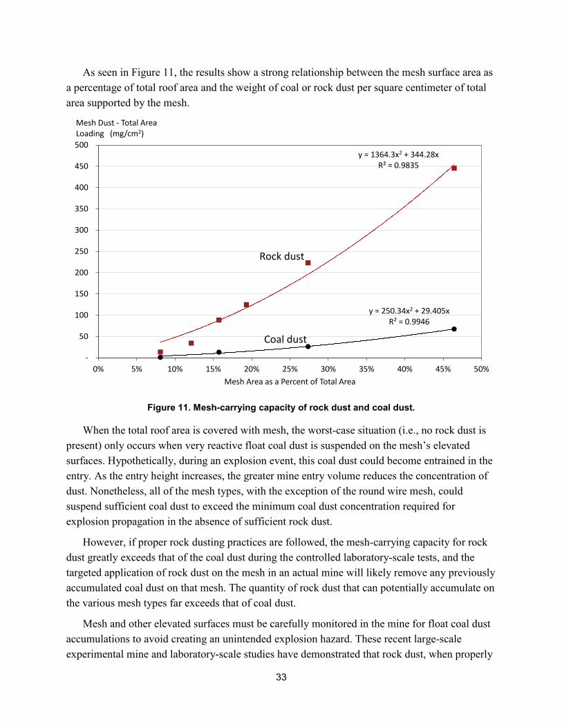
33
As seen in Figure 11, the results show a strong relationship between the mesh surface area as a percentage of total roof area and the weight of coal or rock dust per square centimeter of total area supported by the mesh.
Figure 11. Mesh-carrying capacity of rock dust and coal dust.
y = 1364.3x2 + 344.28xR² = 0.9835
y = 250.34x2 + 29.405xR² = 0.9946
-
50
100
150
200
250
300
350
400
450
500
0% 5% 10% 15% 20% 25% 30% 35% 40% 45% 50%
Mesh Dust - Total Area Loading (mg/cm2)
Mesh Area as a Percent of Total Area
Coal dust
Rock dust
When the total roof area is covered with mesh, the worst-case situation (i.e., no rock dust is present) only occurs when very reactive float coal dust is suspended on the mesh’s elevated surfaces. Hypothetically, during an explosion event, this coal dust could become entrained in the entry. As the entry height increases, the greater mine entry volume reduces the concentration of dust. Nonetheless, all of the mesh types, with the exception of the round wire mesh, could suspend sufficient coal dust to exceed the minimum coal dust concentration required for explosion propagation in the absence of sufficient rock dust.
However, if proper rock dusting practices are followed, the mesh-carrying capacity for rock dust greatly exceeds that of the coal dust during the controlled laboratory-scale tests, and the targeted application of rock dust on the mesh in an actual mine will likely remove any previously accumulated coal dust on that mesh. The quantity of rock dust that can potentially accumulate on the various mesh types far exceeds that of coal dust.
Mesh and other elevated surfaces must be carefully monitored in the mine for float coal dust accumulations to avoid creating an unintended explosion hazard. These recent large-scale experimental mine and laboratory-scale studies have demonstrated that rock dust, when properly
34
applied to the mesh, can significantly add to the overall availability of rock dust in the event of an explosion. However, float coal dust accumulations on some mesh products can be of sufficient quantity to propagate an explosion if proper rock dusting practices are not followed. Proper rock dusting practices, including focused attention to the mine roof and ribs, will help mitigate float coal dust accumulations on mesh or other elevated horizontal surfaces [Alexander and Chasko 2014].
Wet Rock Dusting
The term wet rock dusting is the process of applying rock dust in a wet manner (including foam rock dust) to the ribs and roof surfaces of a coal mine. Through current policy, MSHA allows wet rock dusting of the roof and ribs if the incombustible content is still maintained and if dry rock dust is applied after the wet rock dust dries [MSHA 2014b]. The MSHA policy requires the rock dust to meet 30 CFR 75.2 specifications and that it be applied at a coverage rate of 3 oz/ft2 surface area. Dry rock dust must still be maintained on the floor.
The application of wet rock dust coats the rib and roof surfaces, encapsulates accumulations of freshly generated float coal dust, and increases visibility at the face area when applied. The main benefit of wet rock dusting is that it can occur without stopping coal production, whereas mechanically applied dry rock dust requires the withdrawal of mine workers because of the increased dust suspension, which significantly reduces visibility and contributes to the miners’ total mine and respirable dust exposures.
Wet rock dusting application studies were conducted by NIOSH researchers in the Safety Research Coal Mine (SRCM) and in a West Virginia operating mine. These evaluations only focused on wet rock dusting using the batch slurry process. For the wet rock dusting application trials within the SRCM, two areas were prepared for application of two types of rock dust—a marble rock dust (Rock Dust A) and a limestone rock dust (Rock Dust B). The two areas within the SRCM represented are: (1) short-term wet conditions on coal and (2) long-term wet conditions on coal. Based on the applications and subsequent data analyses of the wet rock dusting applications within the SRCM (for details on the application trials and data, refer to Figure 12 and also Appendix G), the following observations are offered:
• The initial application of the wet rock dust (wet paste) did not disperse with a blast of air from a can of compressed air.10
10The can of compressed air when held at an ~20° angle so that the nozzle is 1.25 in from the dusted surface mimics localized wind forces (i.e., a “light blast of air” as part of the rock dust definition of 30 CFR 75.2), similar to those measured during full-scale coal dust explosions within the Lake Lynn Experimental Mine (LLEM). For dispersible dusts, a cloud of dust particles dislodges from the mine surface; for nondispersible dusts, little to no dust dislodges from the mine surface.
35
• The wet rock dust, when dried, formed a solid cake and did not disperse with a blastof air from a can of compressed air.
• The wet rock dust would not dry in the mine under the humid summer conditions(>90% relative humidity).
• The minimum required wet rock dust coverage rate of 3 oz/ft2 (916 g/m2) could notbe achieved using batch slurries containing 7 gal (26.5 L) of water per 100 lb (45 kg)of rock dust. Batch slurries consisting of a maximum of 4 gal (15 L) of water per 100lb (45 kg) of rock dust did meet the minimum coverage rate of 3 oz/ft2 (915 g/m2).
Based on the applications and subsequent data analyses of the wet rock dusting applications within the West Virginia mine, the following observations are offered:
• The humidity in the West Virginia mine ranged from 73% to 53% from the time theapplication was made until it was dry 24 hr later. Drying proceeded quickly underwinter conditions to less than 0.5% moisture the next day.
• The wet rock dust formed a crust or cake after drying and did not disperse under ablast of air from a can of compressed air.
• The minimum required wet rock dust coverage rate on the mine roof and ribs of 3oz/ft2 (916 g/m2) could not be achieved using batch slurries containing 5 gal and 6 gal(19–23 L) of water per 100 lb of rock dust. Very thick batch slurries consisting of amaximum of 4 gal (15 L) of water per 100 lb (45 kg) of rock dust did exceed theminimum coverage rate of 3 oz/ft2 (916 g/m2) on the mine roof and ribs.
The drying times of the wet rock dusts are dependent on the relative humidity conditions at the mine. A drying time that matches the production cycle in the coal mine may be needed to ensure that the application of dry rock dust can proceed as soon as possible after the section advances. Mine operators must also consider the proportions of water and rock dust used because the end application density and coverage rate is dependent on the particle size distribution of the rock dust (refer to discussion in Appendix G). After the wet rock dust dries, dry rock dust must be applied to all surfaces that were wet dusted to ensure that a dispersible dust is present. Careful attention to the drying time of the wet rock dust must be taken because the drying time can significantly differ depending on the humidity and dampness condition of the mine; i.e., drying times are much shorter in the low-humidity winter months as compared to the humid summer months. Of course, if the wet-applied rock dust does not dry, it does not provide any hazard protection other than the encapsulation of the float coal dust at the time of application. Only by removing and analyzing a representative sample from the wet rock dusting application area can an inspector or mine operator determine that the application met the minimum specified coverage rate of 3 oz/ft2 (916 g/m2).
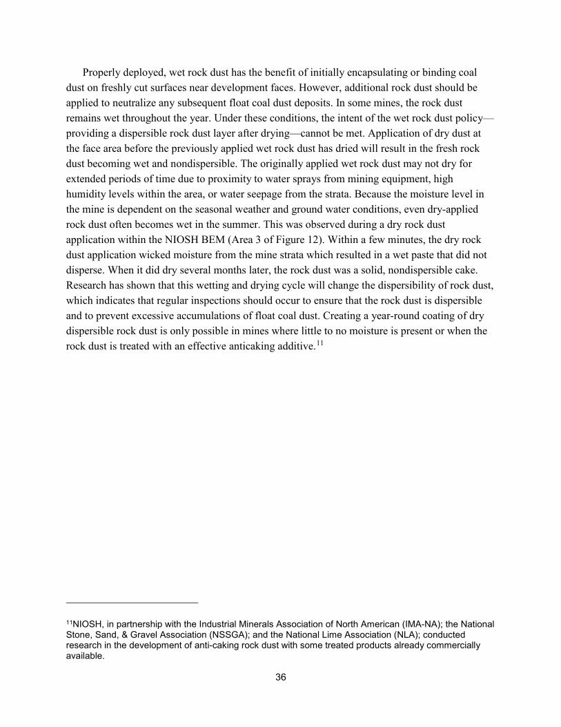
36
Properly deployed, wet rock dust has the benefit of initially encapsulating or binding coal dust on freshly cut surfaces near development faces. However, additional rock dust should be applied to neutralize any subsequent float coal dust deposits. In some mines, the rock dust remains wet throughout the year. Under these conditions, the intent of the wet rock dust policy—providing a dispersible rock dust layer after drying—cannot be met. Application of dry dust at the face area before the previously applied wet rock dust has dried will result in the fresh rock dust becoming wet and nondispersible. The originally applied wet rock dust may not dry for extended periods of time due to proximity to water sprays from mining equipment, high humidity levels within the area, or water seepage from the strata. Because the moisture level in the mine is dependent on the seasonal weather and ground water conditions, even dry-applied rock dust often becomes wet in the summer. This was observed during a dry rock dust application within the NIOSH BEM (Area 3 of Figure 12). Within a few minutes, the dry rock dust application wicked moisture from the mine strata which resulted in a wet paste that did not disperse. When it did dry several months later, the rock dust was a solid, nondispersible cake. Research has shown that this wetting and drying cycle will change the dispersibility of rock dust, which indicates that regular inspections should occur to ensure that the rock dust is dispersible and to prevent excessive accumulations of float coal dust. Creating a year-round coating of dry dispersible rock dust is only possible in mines where little to no moisture is present or when the rock dust is treated with an effective anticaking additive.11
11NIOSH, in partnership with the Industrial Minerals Association of North American (IMA-NA); the National Stone, Sand, & Gravel Association (NSSGA); and the National Lime Association (NLA); conducted research in the development of anti-caking rock dust with some treated products already commercially available.
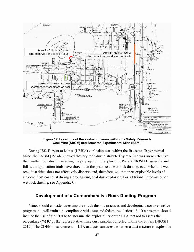
37
Figure 12. Locations of the evaluation areas within the Safety Research Coal Mine (SRCM) and Bruceton Experimental Mine (BEM).
During U.S. Bureau of Mines (USBM) explosion tests within the Bruceton Experimental Mine, the USBM [1956b] showed that dry rock dust distributed by machine was more effective than wetted rock dust in arresting the propagation of explosions. Recent NIOSH large-scale and full-scale application trials have shown that the practice of wet rock dusting, even when the wet rock dust dries, does not effectively disperse and, therefore, will not inert explosible levels of airborne float coal dust during a propagating coal dust explosion. For additional information on wet rock dusting, see Appendix G.
Development of a Comprehensive Rock Dusting Program
Mines should consider assessing their rock dusting practices and developing a comprehensive program that will maintain compliance with state and federal regulations. Such a program should include the use of the CDEM to measure the explosibility or the LTA method to assess the percentage (%) IC of the representative mine dust samples collected within the entries [NIOSH 2012]. The CDEM measurement or LTA analysis can assess whether a dust mixture is explosible
38
or less than 80% IC, respectively. However, the CDEM can give an immediate explosibility determination based on optical reflectance which accounts for particle size influences, whereas the LTA method of analysis requires carrying the dust sample out of the mine to laboratory facilities for weight measurements and burning of the moisture and combustible content. The LTA method does not account for the particle size of the coal dust or rock dust in the sample mixture. After re-rock dusting a deficient area, the CDEM can provide an immediate verification that sufficient rock dust has been applied to correct the deficient conditions, or the sample can be analyzed using the LTA method with results that are not available for days or weeks.
If a proper log book is maintained, rock dust deficient areas can be identified and subsequent schedules provided for applying additional rock dust in a timely manner. The log book can also demonstrate the efforts the mine has taken in its rock dusting operations and the efforts to correct the rock dust deficient conditions, including listing the dates and times of sampling and subsequent rock dusting efforts, the amount of rock dust applied to a given area, the names of personnel associated with the sampling and rock dusting, conditions that may have led to excessive float coal dust accumulations, and many other related items. A mine can also routinely assess the log book to identify any potential shortcomings in its rock dust practices. Trends in rock dust usage may identify areas that constantly require additional rock dusting and remediation efforts. Rock duster output can be monitored to ensure that the amount of rock dust distributed is sufficient to maintain 80% TIC or to determine if a higher capacity machine is needed to meet the requirement. Ideally, such a program would demonstrate the proactive intentions of the mine operator in the company’s rock dusting efforts and in locating areas deficient in rock dust along with subsequent efforts in mitigating deficient conditions. Documentation of this type can display due diligence in rock dusting and demonstrate that rock dust deficient conditions are being identified and corrected in a timely manner.
Summary
The goal of this NIOSH research study is to provide coal mine operators with relevant information that can result in improved rock dusting practices. Hazardous coal and float coal dust accumulations are mitigated when dust throughout their mine is maintained to at least 80% TIC. Achieving this level of success is only possible when the mine operators and their personnel are proactive in their rock dusting efforts, including developing and following a detailed, comprehensive rock dusting program.
As a means to achieve this research goal, NIOSH researchers gathered samples from continuous miner sections, longwall tailgates, conveyor belt entries, and outby transfer points at nine participating mines; conducted experiments within experimental mines and operating mines; and collected data from discussions with mine operators and enforcement personnel. The sampling results revealed that continuous miner sections having ≥ 80% IC ranged from a high of
39
96% of the samples to a low of 29% of the samples. The combined results for all mine dust samples collected in the continuous miner sections showed that 69% of the samples were ≥ 80% IC. Sampling results in the longwall tailgate entries produced similar results. The sampling results revealed that longwall tailgate entry sections having ≥ 80% IC ranged from a high of 100% of the samples to a low of 22% of the samples. The combined results for all mine dust samples collected in the longwall tailgate entry sections showed that 54% of the samples were ≥ 80% IC. Of the 507 mine dust samples taken in the continuous miner sections and the longwall tailgates, 160, or nearly 32%, of the samples were < 80% IC.
Mine operators who take a proactive approach to rock dusting had the most success in terms of much higher ratings—i.e., the percentage of overall NIOSH collected samples that were ≥ 80% IC. Some of the mine operators are taking their own mine dust samples to determine the % TIC. This information is key to the mine operators making informed decisions on the adequacy of their rock dusting procedures and where additional rock dust must be applied.
The following actions can be taken to improve rock dusting in continuous miner sections:
• Use machine-mounted rock dusters at the face area to provide even rock dust coverage; hand dusting should be avoided or kept to a minimum.
• Always operate the rock duster when the continuous miner is cutting and loading coal.
• When permitted, use a flooded-bed scrubber that removes dust particles from the airstream close to the source and discharges cleaned air back into the mine.
• Where continuous miners are equipped with scrubbers, the scrubbers should be running while the continuous mining machine’s cutterhead is operating.
• Rock dusters for return airways should be operating when the continuous miner is in operation. If the return rock duster is not operating, the operator should consider not operating the continuous miner until the rock duster is operational. If the continuous miner is permitted to continue operation while the rock duster is out of service, the float coal dust will continue to accumulate in the return entry. In time, this could allow a potential explosion hazard to be created.
• Rock dust discharge points should be oriented horizontally, close to the mine roof, oriented in the same direction as airflow, and located near the center of the entry to allow for optimal transport of the rock dust down the entry.
• Wetting roadways with water or calcium chloride is an effective method of reducing the dispersion of roadway dust.
• Drag bars used to smooth out roadways are an effective tool for minimizing float coal dust surface accumulations, but frequent sampling must be taken to ensure that the raked dust is ≥ 80% TIC.
40
The following actions can be taken to improve rock dusting in longwall sections:
• Where applicable, operators should consider applying a fresh layer of rock dust to thefuture tailgate entry as the present longwall panel retreats. This action will permit rockdusting when access to that future tailgate is much more readily accessible and willincrease the likelihood of achieving ≥ 80% TIC in the existing mine dust prior to thestartup of the new panel.
• Either install a rock duster in the headgate area and pneumatically transport the rockdust to the tailgate entry or install a rock duster near the tailgate entry. Ensure that theduster always has sufficient rock dust and is operating during shearer operation.
• Rock dust discharge points should be oriented horizontally, close to the mine roof,oriented in the same direction as airflow, and located near the center of the entry toallow for the optimal transport of the rock dust down the tailgate.
The following actions can be taken to improve rock dusting along conveyor beltlines and other outby areas of the mine:
• Ensure adequate amounts of rock dust are applied to the tight side of the belt as well asthe wide side.
• Ensure adequate amounts of rock dust are applied to the mine floor under the beltstructure.
• Conduct routine examinations of conveyor belt structures for accumulation of coaldust and conduct routine brushing of these belt structures to remove any excessiveaccumulations.
• Minimize the distance the coal drops from a discharge conveyor to the receivingconveyor to reduce coal dust generation.
• Install primary and secondary belt cleaners to reduce belt carryback.
• Install skirt boards at transfer points to keep coal on the receiving conveyor and installdevices to keep the coal on the conveyor belts where belts pass through box checks.Coal that drops onto the mine floor creates a tripping hazard and an area for coal dustto accumulate.
Mesh and other elevated surfaces can hold additional quantities of dust compared to unmeshed areas. Proper rock dusting practices will ensure that this dust is high in IC which, in turn, can provide added benefit in inerting propagating coal dust explosions. Recent NIOSH large-scale experimental mine and laboratory-scale studies have demonstrated that float coal dust accumulations on some mesh products can be of sufficient quantity to propagate an explosion if
41
proper rock dusting practices are not followed. It is important that the dust on mesh and other elevated horizontal surfaces be carefully monitored to prevent excessive float coal dust accumulations.
If properly deployed, wet rock dust can initially encapsulate or bind coal dust on freshly cut surfaces near development faces. However, additional rock dust should be applied to neutralize any subsequent float coal dust deposits. In some mines, the rock dust remains wet throughout the year. Under these conditions, the intent of the wet rock dust policy—providing a dispersible rock dust layer after drying—cannot be met. It should also be emphasized that application of dry dust at the face area before the previously applied wet rock dust has dried will result in the fresh rock dust absorbing moisture and becoming nondispersible. The originally applied wet rock dust may not dry for extended periods of time due to proximity to water sprays from mining equipment, high humidity levels within the area, or water seepage from the strata. Because the moisture level in the mine is dependent on the seasonal weather and ground water conditions, even dry-applied rock dust often becomes wet in the summer. Research has shown that this wetting and drying cycle will change the dispersibility of rock dust so regular inspections must occur to ensure that the rock dust is dispersible and to prevent excessive accumulations of float coal dust. Based on recent large- and full-scale trials conducted by NIOSH, the application of wet rock dust, even when the wet rock dust dries, does not effectively disperse and, therefore, will not inert explosible levels of airborne float coal dust during a propagating coal dust explosion. A propagating coal dust explosion can be inerted by rock dust, but only if sufficient quantities of quality rock dust (rock dust that will disperse into separate particles that meet the specifications of 30 CFR 75.2) is entrained into the entry with the coal dust at a 4:1 ratio (i.e. 80% rock dust to 20% coal dust).
All mine operators should consider assessing their rock dusting practices and develop a comprehensive rock dusting program that will maintain compliance with current regulations. Such a program should include the use of the CDEM to measure the explosibility or the LTA method to assess the % TIC of dust mixtures collected within the mine entries. Maintaining detailed documentation will serve to identify deficient areas that require more timely rock dusting. This documentation will also demonstrate the efforts that the mine has taken to correct the deficient rock dust conditions and to identify shortcomings in its rock dusting practices. Ideally, such a program with detailed documentation would demonstrate the proactive intentions of the mine operator in locating areas deficient in rock dust and subsequently mitigating these deficiencies by adding rock dust. Documentation of this type will display due diligence in the mine’s rock dusting practices and show that deficient rock dust conditions are being identified and corrected in a timely manner.
42
Acknowledgments
The authors would like to acknowledge the nine mine operators and their associated personnel for allowing our access to their mines for the sampling portion of this research effort and their willingness to discuss their rock dusting practices. In addition, we acknowledge the MSHA mine inspectors and District personnel who willingly shared their insights into rock dusting in terms of enforcement and common violations.
The authors also recognize the laboratory and mine assistance of all NIOSH personnel for their efforts in the sample collection and analyses with particular thanks to Linda L. Chasko and James D. Addis, Physical Science Technicians.

43
References
Alexander DW, Chasko LL [2014]. Effect of ground control mesh on dust sampling and explosion mitigation. SME Manuscript TP-14-036.
Anstine D [2013]. Telephone conversation in May 2013, between D. Anstine, limestone processing industry expert, and S. Harteis, National Institute for Occupational Safety and Health, Centers for Disease Control, U.S. Department of Health and Human Services.
Carpenter C [2012]. In-person conversation on March 26, 2012 between C. Carpenter, MSHA District 4, District Manager, and S. Harteis, Lead Mining Engineer, Office of Mine Safety and Health Research, National Institute for Occupational Safety and Health, Centers for Disease Control and Prevention, U.S. Department of Health and Human Services.
CFR. Code of Federal regulations. Washington, D.C.: U.S. Government Printing Office, Office of the Federal Register.
Compton C, Gallagher S, Molinda GM, Mark C, Wilson G [2007]. Roof screening for underground coal mines: recent developments, Proceedings of the 26th International Conference on Ground Control in Mining, July 31–Aug. 2, Morgantown, WV, pp. 270–276.
Cooper K [2013]. Telephone conversation, midyear 2013, between K. Cooper, expert in limestone processing, and S. Harteis, Lead Mining Engineer, Office of Mine Safety and Health Research, National Institute of Occupational Safety and Health, Centers for Disease Control and Prevention, U.S. Department of Health and Human Services.
Cybulski WG [1969]. General formulae embracing the protection of coal dust against the propagation of explosion. Arch. Gornictwa, v. 14, No. 3.
Cybulski WG [1975]. Coal dust explosions and their suppression. Translated from Polish. Warsaw, Poland: National Center for Scientific, Technical and Economic Information. NTIS No. TT 73-54001.
Dezeeuw M [2011]. In person conversation on August 8, 2011, between M. Dezeeuw, Safety Coordinator, Peabody Energy, and S. Harteis, Lead Mining Engineer, Office of Mine Safety and Health Research, National Institute for Occupational Safety and Health, Centers for Disease Control and Prevention, U.S. Department of Health and Human Services.
Greenwald HP [1938]. Recent trends in rock dusting to prevent dust explosions in coal mines. American Institute of Mining and Metallurgical Engineers, Inc., Chicago, IL meeting, October 1938, Technical Publications No. 975.
Harris ML, Weiss ES, Harteis SP, Goodman GVR, Sapko MJ [2010]. Rock dusting considerations in underground coal mines. In: Hardcastle S, McKinnon DL, eds: Proceedings of the 13th Mine Vent Symposium (Laurentian University, Sudbury, Ontario, Canada, June 13–16, 2010). WI: Omnipress, pp. 267–271.
44
Harris ML, Alexander DW [2014]. Moisture variance of mine dust samples and the inclusion of moisture as incombustible content. SME Annual Meeting and Exhibit Preprint 14-145, Salt Lake City, UT, February 24–26, 2014, Society for Mining, Metallurgy, and Exploration, Inc. p. 9.
Harris ML, Alexander DW, Harteis SP, Sapko MJ [2014]. Collecting representative dust samples: a comparison of various sampling methods in underground coal mines. 10th International Symposium on Hazards, Prevention, and Mitigation of Industrial Explosions, Bergen, Norway, June 10–14, 2014.
IMERYS [2014]. Development of an anti-caking rock dust. NIOSH Broad Agency Announcement (BAA): 2012-N-14257, Contract # - 200-2012-52496, April 2014.
Lebecki K [1991]. Gas dynamics of coal dust explosion—theory and experiment. In: Proceedings of the 24th International Conference of Safety in Mines Research Institutes, Donetsk, USSR, September 23–28, vol. 1, pp. 357–373.
Maguire BA, Casswell C [1970]. Fineness of coal dust deposited on the roof and sides of a mine roadway. SMRE Res. Rept. 268.
Michelis J, Margenburg B, Müller G, Kleine W [1987]. Investigations into the buildup and development conditions of coal dust explosions in a 700-m underground gallery. In: Cashdollar KL, Hertzberg M, eds. Industrial dust explosions. West Conshohocken, PA: American Society for Testing and Materials (ASTM), Special Technical Publication (STP) 958, pp. 124–137.
Mines Rescue Board, New South Wales [1998]. Emergency preparedness and mines rescue. By: McKensey BR, Chairman, Mines Rescue Board and Staff, NSW, October 20, 1998, pp. 457.
Mine Safety Board [1937]. Recommendations of United States Bureau of Mines on certain questions of safety as of October 1, 1936. Pittsburgh, PA: U.S. Department of the Interior, Bureau of Mines, IC-6946.
Montgomery T [2005]. In-personal conversation on incombustible analysis procedures on August 8, 2011, between T. Montgomery, Lab Director, MSHA Technical Support, Mine Safety and Health Administration, and S. Harteis, Lead Mining Engineer, Office of Mine Safety and Health Research, National Institute for Occupational Safety and Health, Centers for Disease Control and Prevention, U.S. Department of Health and Human Services.
MSHA [1981]. The explosion hazard in mining. By Nagy J. Pittsburgh, PA: U.S. Department of Labor, Mine Safety and Health Administration, IR 1119.
MSHA [1996]. Program policy manual, Volume I. Interpretation and guidelines on enforcement of the 1977 Act, May 16, 1996. Section 104(a), Citations and Orders. http://arlweb.msha.gov/REGS/COMPLIAN/PPM/PMVOL1C.htm.

45
MSHA [2002]. Report of investigation, fatal underground coal mine explosions, September 23, 2001. No. 5 Mine, Jim Walters Resources, Inc., Brookwood, Tuscaloosa County, Alabama, ID No. 01–01322. By McKinney R, Crocco W, Stricklin KG, Murray KA, Blankenship ST, Davidson RD, Urosek JE, Stephan CR, Beiter DA. Arlington, VA: U.S. Department of Labor, Mine Safety and Health Administration.
MSHA [2010]. Emergency temporary standard, maintenance of incombustible content of rock dust in underground coal mines, Federal Register /Vol. 75, No. 184/Thursday, September 23, 2010 /Rules and Regulations, https://webapps.dol.gov/federalregister/PdfDisplay.aspx?DocId=24264.
MSHA [2011]. Fatal underground mine explosion, April 5, 2010. Performance Coal Company Upper Big Branch Mine–South, Massey Energy Company, Mine ID: 46-08436. Arlington, VA: U.S. Department of Labor, Mine Safety and Health Administration, December 6, 2011.
MSHA [2013a]. Program for regular cleanup and removal of accumulations of coal and float coal dust, loose coal, and other combustibles. Program policy letter no. P13-V-11, December 18, 2013, http://www.msha.gov/regs/complian/ppls/2013/PPL13-V-11.asp, accessed 3/14/2014.
MSHA [2013b]. MSHA handbook series, Coal mine health inspection procedures, Handbook number: PH89-V-1 (25), U.S. Department of Labor, Mine Safety and Health Administration, Coal Mine Safety and Health, http://www.msha.gov/READROOM/HANDBOOK/Coal%20Health%20Chapter%201.pdf, Revised August 2014, accessed 08/20/2015.
MSHA [2013c]. MSHA—Revised policies and procedures for the prevention of coal dust explosions, http://www.msha.gov/focuson/handbookrockdust/RockDustRevisedPolicies.pdf. Date accessed: 4/8/2014.
MSHA [2013d]. Coal GIP handbook changes. Cleanup program. http://www.msha.gov/focuson/handbookrockdust/CoalGIPHandbookChanges.pdf. Date accessed: 04/08/2014.
MSHA [2014a]. Most frequently cited standards by mine type, http://www.msha.gov/STATS/Top20Viols/top20home.asp. Date accessed: 5/03/2016.
MSHA [2014b] MSHA—Program Policy Manual, Volume V—Coal Mines Subpart E, 75.403 Maintenance of Incombustible Content of Rock Dust, http://www.msha.gov/REGS/COMPLIAN/PPM/PMVOL5E.HTM. Date accessed: 12/08/2014.
MSHA [2016]. MSHA handbook series, Coal mine health inspection procedures, Handbook number: PH89-V-1 (27), Chapter 7, U.S. Department of Labor, Mine Safety and Health Administration, Coal Mine Safety and Health, June 2016. Section E, Sampling Inspection Procedures, #12. http://arlweb.msha.gov/READROOM/HANDBOOK/Coal%20Health%20Chapter%201.pdf. Date accessed: 10/17/2016.

46
National Coal Board [1967]. Final report of working party on coal dust explosions. London, July 1967.
NIOSH [2006a]. Technology news 515, Float coal dust explosion hazards. Pittsburgh, PA: U.S. Department of Health and Human Services, Public Health Service, Centers for Disease Control and Prevention, National Institute for Occupational Safety and Health, DHHS (NIOSH) Publication No. 2006-125.
NIOSH [2006b]. Handbook for methane control in mining. By Kissell F. U.S. Department of Health and Human Services, Centers for Disease Control and Prevention, National Institute for Occupational Safety and Health. IC-9486.
NIOSH [2010a]. Recommendations for a new rock dusting standard to prevent coal dust explosions in intake airways. By Cashdollar KL, Sapko MJ, Weiss ES, Harris ML, Man CK, Harteis SP, Green GM: U.S. Department of Health and Human Services, Centers for Disease Control and Prevention, National Institute for Occupational Safety and Health, DHHS (NIOSH) Publication No. 2010-151.
NIOSH [2010b]. Best practices for dust control in coal mining. By Colinet JF, Rider JP, Listak JM, Organiscak JA, Wolfe AL. Pittsburgh, PA: U.S. Department of Health and Human Services, Centers for Disease Control and Prevention, National Institute for Occupational Safety and Health, DHHS (NIOSH) Publication No. 2010-110, Information Circular 9517, 2010 Jan; pp. 1–76, p 48.
NIOSH [2012]. Coal dust explosibility meter evaluations and recommendations for application. By Harris ML, Sapko MJ, Varley FD, Weiss ES: U.S. Department of Health and Human Services, Centers for Disease Control and Prevention, National Institute for Occupational Safety and Health, DHHS (NIOSH) Publication No. 2012-172.
NIOSH [2013]. Impact on respirable dust levels when operating a flooded-bed scrubber in 20-foot cuts. By Colinet JF, Reed WR, Potts J. Pittsburgh, PA: U.S. Department of Health and Human Services, Public Health Service, Centers for Disease Control and Prevention, National Institute for Occupational Safety and Health, DHHS (NIOSH) Publication No. 2014-105, RI 9693, pp. 1–59.
Perera IE, Sapko MJ, Harris ML, Zlochower IA, Weiss EW [2015]. Design and development of a dust dispersion chamber to quantify the dispersibility of rock dust. Journal of Loss Prevention, June, 2015.
Reed D, Michelis J [1989]. Comparative investigation into explosibility of brown coal and bituminous coal dust in surface and underground test installations. In: Proceedings of the 23rd International Conference of Safety in Mines Research Institutes, Washington, D.C., September 11–15, 1989. Pittsburgh, PA: U.S. Department of the Interior, Bureau of Mines, pp. 941–964.
47
Reichardt J [2014]. Telephone conversation in mid-2014 between J. Reichardt, Geologist and Mining Engineer, Jesse Creek Mining, and Danrick Alexander, Research Physical Scientist. U.S. Department of Health and Human Services, Centers for Disease Control and Prevention, National Institute for Occupational Safety and Health, Office of Mine Safety and Health Research. Pittsburgh, PA.
Sapko MJ, Weiss ES, Watson RW [1987]. Explosibility of float coal dust distributed over a coal-rock dust substratum. In: Proceedings of the 22nd International Conference of Safety in Mines Research Institutes. Beijing, China, November 2–6, 1987. Beijing, China: China Coal Industry Publishing House, pp. 459–468.
Triebsch GF, Sapko MJ [1990]. Lake Lynn Laboratory: a state-of-the-art mining research laboratory. In: Proceedings of the International Symposium on Unique Underground Structures. Golden, CO: Colorado School of Mines, Vol. 2, pp. 75-1 to 75-21.
USBM [1911]. The explosibility of coal dust. By Rice GS. Washington, D.C.: Department of the Interior, Bureau of Mines, Bulletin 20.
USBM [1913]. Notes on the prevention of explosions in coal mines. By Rice GS. Pittsburgh, PA: U.S. Department of the Interior, Bureau of Mines, Technical Paper 56.
USBM [1922]. Coal-dust explosion tests in the experimental mine, 1913 to 1918, inclusive. By Rice GS, Jones LM, Egy WL, Greenwald HP. Washington, D.C.: Bureau of Mines, Bulletin 167.
USBM [1927a]. Effective rock-dusting of coal mines. By Rice GS. Pittsburgh, PA: U.S. Department of the Interior, Bureau of Mines, IC 6039.
USBM [1927b]. Coal-dust explosion tests in the experimental mine, 1919–24, inclusive. Rice GS, Paul JW, Greenwald HP. Washington, D.C.: Bureau of Mines, Bulletin 268.
USBM [1930]. Explosion tests of Pittsburgh coal dust in the experimental mine, 1925 to 1932, inclusive. By Rice GS, Greenwald HP, Howarth HC. Washington, D.C.: Bureau of Mines, Bulletin 369.
USBM [1940]. Methods of sampling and analyzing coal-mine dusts for incombustible content. By Owings CW, Selvig WA, Greenwald HP. Pittsburgh, PA: U.S. Department of the Interior, Bureau of Mines, IC 7113.
USBM [1954]. Incombustible required on floor and on rib-roof surfaces of coal mines to prevent propagation of explosions. By Hartmann I, Nagy J, Christofel FP. Pittsburgh, PA: U.S. Department of the Interior, Bureau of Mines, RI 5053.
USBM [1956a]. Rock dusting and sampling including wet rock dusting, at the Bureau of Mines experimental coal mine. By Hartmann I, Westfield J. Pittsburgh, PA: U.S. Department of the Interior, Bureau of Mines, IC 7755.
48
USBM [1956b]. Coal-mine-explosion research by the Bureau of Mines, 1954-55. By Hartmann I, Nagy J, Rauschenberger JK, Mitchell DW. Pittsburgh, PA: U.S. Department of the Interior, Bureau of Mines, RI 5264.
USBM [1960a]. American standard practice for rock-dusting underground bituminous-coal and lignite mines to prevent coal-dust explosions (ASA standard M13.1-1960, UDC 622.81). U.S. Department of the Interior, Bureau of Mines, Information Circular 8001.
USBM [1960b]. Historical summary of coal-mine explosions in the U.S., 1810–1958. Pittsburgh, PA: U.S. Department of the Interior, Bureau of Mines, Bulletin 586.
USBM. [1962]. Water as an inert for neutralizing the coal-dust explosion hazards. By Mitchell D, Nagy J. Pittsburgh, PA: U.S. Department of the Interior, Bureau of Mines, IC 8111.
USBM [1965]. Float coal hazard in mines: a progress report. By Nagy J, Mitchell DW, Kawenski EM. Pittsburgh, PA: U.S. Department of the Interior, Bureau of Mines, RI 6581.
USBM [1975]. Effect of rock dust on explosibility of coal dust. By Richmond JK, Liebman I, Miller LF. Pittsburgh, PA: U.S. Department of the Interior, Bureau of Mines, RI 8077.
USBM [1996]. Historical summary of coal mine explosions in the United States, 1981–1994. By Dobroski H Jr., Stephan CR, Conti RS. Pittsburgh, PA: U.S. Department of the Interior, Bureau of Mines, IC 9440.
USBM [1981]. Suppression of coal dust explosion by water barrier in a conveyor belt entry. U.S. Department of the Interior, Bureau of Mines, RI-8538.
USBM [1983a]. Historical summary of coal mine explosions in the United States, 1959–81. By Richmond JK, Price GC, Sapko MJ, Kawenski EM. Pittsburgh, PA: U.S. Department of the Interior, Bureau of Mines, IC 8909.
USBM [1983b]. Lake Lynn Laboratory: construction, physical description, and capability. By Mattes RH, Bacho A, Wade LV. Pittsburgh, PA: U.S. Department of the Interior, Bureau of Mines, IC 8911.
USBM [1990]. Laboratory evaluation of quartz dust capture of irrigated-filter collection systems for continuous miners. By Colinet JF, McClelland JJ, Erhard LA, Jankowski RA. Pittsburgh, PA: U.S. Department of the interior, Bureau of Mines, RI 9313.
Weiss ES, Greninger NB, Sapko MJ [1989]. Recent results of dust explosion studies at the Lake Lynn Experimental Mine. In: Proceedings of the 23rd International Conference of Safety in Mines Research Institutes (Washington, D.C., September 11–15, 1989). Pittsburgh, PA: U.S. Department of the Interior, Bureau of Mines, pp. 843–856.
Zou DH, Panawalage S [2001]. Passive and triggered explosion barriers in underground coal mines—A literature review of recent research. Final report to CANMET, September, 2001.
49
Appendix A: Mine Dust Samples and Results from Continuous Miner Sections
Table 7 provides a summary of the mine dust sampling results from the advancing continuous miner sections sampled at each of the nine operating mines. All samples were representative of the dust in that area.
Table 7. Continuous miner mine dust samples and percentage of samples ≥ 80%
a. Mines A, B, and C
Sample area Mine A no. of samples
Mine A % of samples
≥ 80% Mine B no. of Samples
Mine B % of samples
≥ 80% Mine C no. of samples
Mine C % of samples
≥ 80%
Floor 21 71 1 89 20 70
Rib 21 43 12 92 22 95
Roof 21 24 9 56 22 59
Structure 6 33 5 20 3 100
Overall 69 45 27 76 67 76
b. Mines D, E, and F
Sample Area
Mine D No. of
samples
Mine D % of samples
≥ 80%
Mine E No. of
samples
Mine E % of samples
≥ 80%
Mine F No. of
samples
Mine F % of samples
≥ 80%
Floor 12 58 21 52 7 57
Rib 12 92 23 52 14 43
Roof 12 92 24 92 12 50
Structure 0 No sample 10 70 2 50
Overall 36 81 78 67 35 49
50
c. Mines G, H, and I
Sample Area Mine G no. of samples
Mine G % of samples
≥ 80% Mine H no. of samples
Mine H % of samples
≥ 80%
Mine I no. of
samples
Mine I % of samples
≥ 80%
Floor 20 90 19 58 7 14
Rib 15 100 22 68 3 67
Roof 17 100 22 100 2 50
Structure 5 100 5 100 2 0
Overall 57 96 68 78 14 29
d. Combined sample data from Mines A–I
Sample area Combined no.
of samples Combined % of samples ≥ 80%
Floor 146 67
Rib 144 71
Roof 141 72
Structure 38 64
Overall 469 69
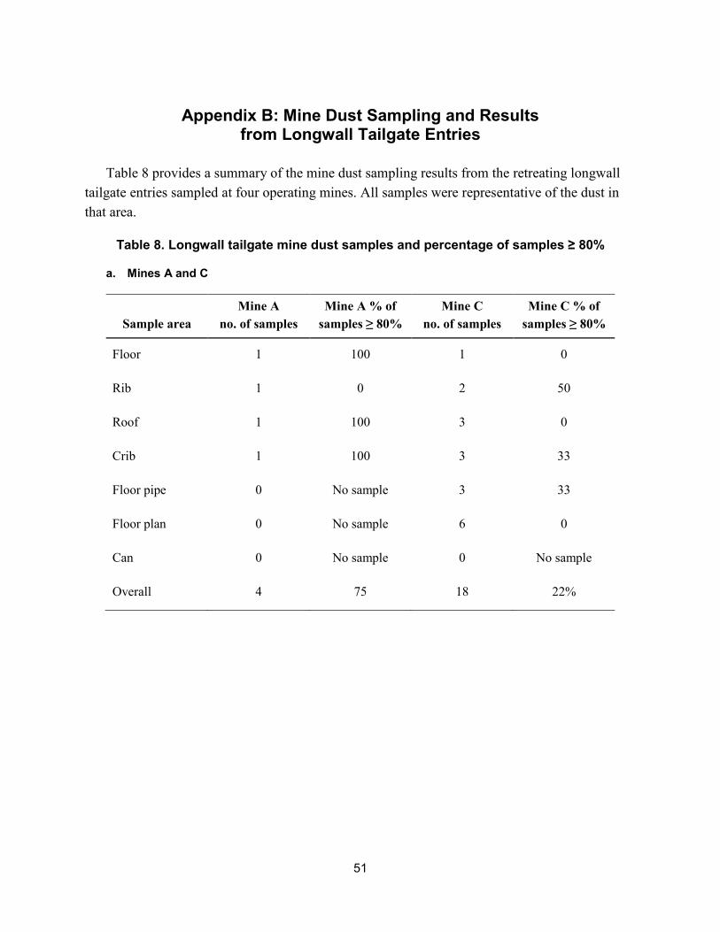
51
Appendix B: Mine Dust Sampling and Results from Longwall Tailgate Entries
Table 8 provides a summary of the mine dust sampling results from the retreating longwall tailgate entries sampled at four operating mines. All samples were representative of the dust in that area.
Table 8. Longwall tailgate mine dust samples and percentage of samples ≥ 80%
a. Mines A and C
Sample area Mine A
no. of samples Mine A % of
samples ≥ 80% Mine C
no. of samples Mine C % of
samples ≥ 80%
Floor 1 100 1 0
Rib 1 0 2 50
Roof 1 100 3 0
Crib 1 100 3 33
Floor pipe 0 No sample 3 33
Floor plan 0 No sample 6 0
Can 0 No sample 0 No sample
Overall 4 75 18 22%
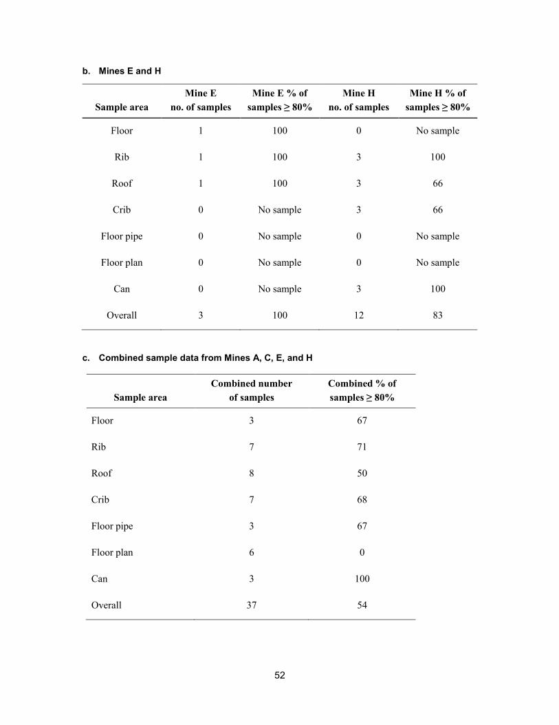
52
b. Mines E and H
Sample area Mine E
no. of samples Mine E % of
samples ≥ 80% Mine H
no. of samples Mine H % of
samples ≥ 80%
Floor 1 100 0 No sample
Rib 1 100 3 100
Roof 1 100 3 66
Crib 0 No sample 3 66
Floor pipe 0 No sample 0 No sample
Floor plan 0 No sample 0 No sample
Can 0 No sample 3 100
Overall 3 100 12 83
c. Combined sample data from Mines A, C, E, and H
Sample area Combined number
of samples Combined % of samples ≥ 80%
Floor 3 67
Rib 7 71
Roof 8 50
Crib 7 68
Floor pipe 3 67
Floor plan 6 0
Can 3 100
Overall 37 54

53
Appendix C: Survey Results from Operators and Enforcement Personnel
NIOSH researchers met with MSHA mine inspectors at the Mine Academy in Beckley, West Virginia, during a training event that was being held there. The meeting provided an opportunity to discuss rock dusting practices, common violations, and related information that the inspectors witness every day in the field. Tables 9–23 are the inspectors’ responses to a list of questions related to rock dusting practices. The number in parentheses refers to the number of MSHA inspectors that provided a given response to a particular question. MSHA District 1 and 11 did not participate in this training event.
Table 9. Participating MSHA districts and participants (not all individuals participated in survey)
MSHA district number Number of
participants
Unknown (district not listed on form)
1
2 6
3 3
4 3
5 3
6 6
7 2
8 5
9 2
10 3
12 1
Total 35
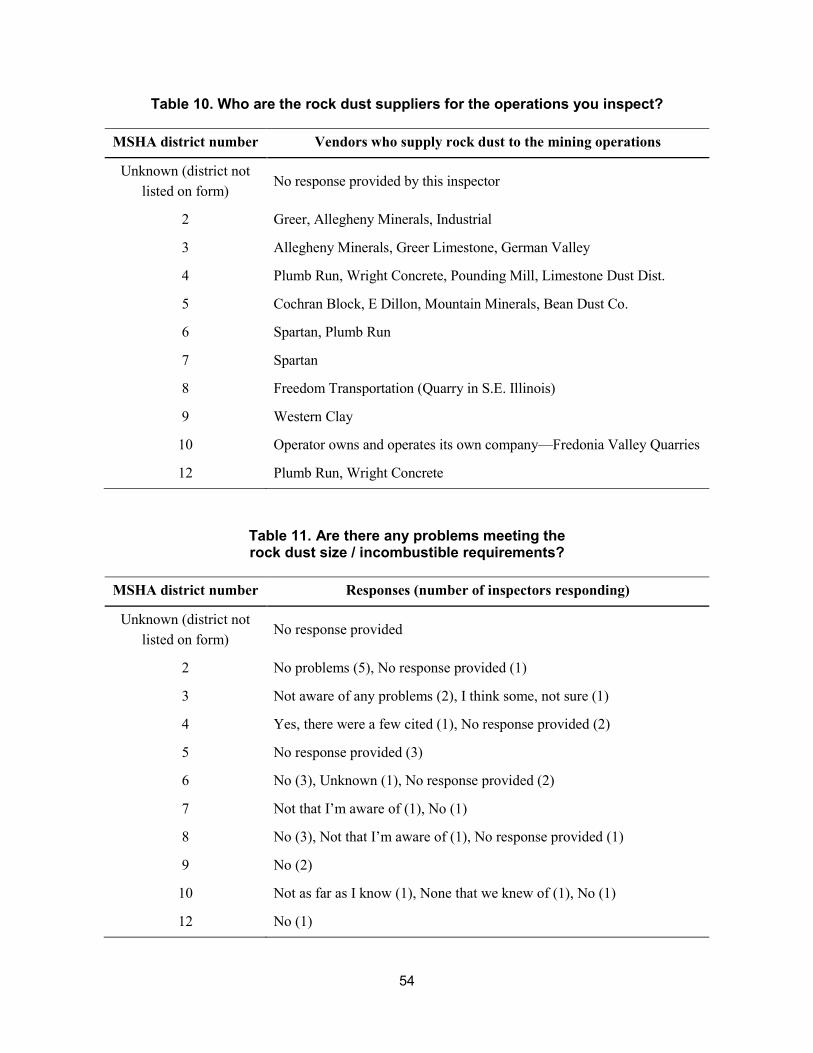
54
Table 10. Who are the rock dust suppliers for the operations you inspect?
MSHA district number Vendors who supply rock dust to the mining operations
Unknown (district not listed on form)
No response provided by this inspector
2 Greer, Allegheny Minerals, Industrial
3 Allegheny Minerals, Greer Limestone, German Valley
4 Plumb Run, Wright Concrete, Pounding Mill, Limestone Dust Dist.
5 Cochran Block, E Dillon, Mountain Minerals, Bean Dust Co.
6 Spartan, Plumb Run
7 Spartan
8 Freedom Transportation (Quarry in S.E. Illinois)
9 Western Clay
10 Operator owns and operates its own company—Fredonia Valley Quarries
12 Plumb Run, Wright Concrete
Table 11. Are there any problems meeting the rock dust size / incombustible requirements?
MSHA district number Responses (number of inspectors responding)
Unknown (district not listed on form)
No response provided
2 No problems (5), No response provided (1)
3 Not aware of any problems (2), I think some, not sure (1)
4 Yes, there were a few cited (1), No response provided (2)
5 No response provided (3)
6 No (3), Unknown (1), No response provided (2)
7 Not that I’m aware of (1), No (1)
8 No (3), Not that I’m aware of (1), No response provided (1)
9 No (2)
10 Not as far as I know (1), None that we knew of (1), No (1)
12 No (1)

55
Table 12. How do the mining operations verify that the rock dust they purchase meets the particle size requirements?
MSHA district number Responses (number of inspectors responding)
Unknown (district not listed on form)
No response provided
2 Certification from the rock dust supplier (4), No response provided (2 no response)
3 Certification from the rock dust supplier (3)
4 Certification from the rock dust supplier (2), Obtain lab analysis (1), No response provided (1)
5 Certification from the rock dust supplier (3)
6 Certification from the rock dust supplier (4), Unknown (2)
7 Certification from the rock dust supplier (2)
8 Certification from the rock dust supplier (3), Obtain lab analysis (2), No response provided (1)
9 Certification from the rock dust supplier (3), Certification on the bag (1), Obtain lab analysis (1), Obtain lab sample (on request) (1)
10 Certification from the rock dust supplier (2), Obtain lab analysis (1), Other (1)
12 Certification from the rock dust supplier (1)
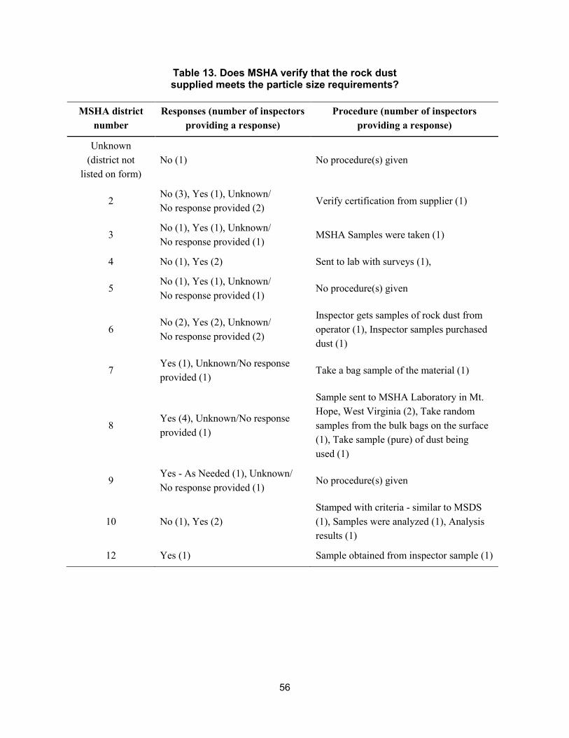
56
Table 13. Does MSHA verify that the rock dust supplied meets the particle size requirements?
MSHA district number
Responses (number of inspectors providing a response)
Procedure (number of inspectors providing a response)
Unknown (district not
listed on form) No (1) No procedure(s) given
2 No (3), Yes (1), Unknown/ No response provided (2)
Verify certification from supplier (1)
3 No (1), Yes (1), Unknown/ No response provided (1)
MSHA Samples were taken (1)
4 No (1), Yes (2) Sent to lab with surveys (1),
5 No (1), Yes (1), Unknown/ No response provided (1)
No procedure(s) given
6 No (2), Yes (2), Unknown/ No response provided (2)
Inspector gets samples of rock dust from operator (1), Inspector samples purchased dust (1)
7 Yes (1), Unknown/No response provided (1)
Take a bag sample of the material (1)
8 Yes (4), Unknown/No response provided (1)
Sample sent to MSHA Laboratory in Mt. Hope, West Virginia (2), Take random samples from the bulk bags on the surface (1), Take sample (pure) of dust being used (1)
9 Yes - As Needed (1), Unknown/ No response provided (1)
No procedure(s) given
10 No (1), Yes (2) Stamped with criteria - similar to MSDS (1), Samples were analyzed (1), Analysis results (1)
12 Yes (1) Sample obtained from inspector sample (1)

57
Table 14. How is rock dust received at the operations?
MSHA district number
40–50 lb bags, number of
YES responses
Super bags, number of
YES responses
Bulk, number of
YES responses
Unknown (district not listed on form)
0 1 1
2 6 4 6
3 3 3 3
4 3 3 3
5 3 3 3
6 6 5 2
7 2 2 1
8 5 5 4
9 1 0 1
10 3 3 3
12 1 1 1

58
Table 15. Are mines purchasing rock dust from more than one supplier?
MSHA district number
Number of YES responses from MSHA
inspectors
Number of NO responses from MSHA
inspectors
No response from MSHA
inspectors
Unknown (district not listed
on form) 1 - -
2 1 3 2
3 3 - -
4 2 1 -
5 3 - -
6 4 2 -
7 1 1 -
8 4 - 1
9 2 - -
10 - 3 -
12 1 - -

59
Table 16. Have you noticed or identified any problems in using the above-ground storage tanks?
MSHA district number
Number of YES responses from MSHA
inspectors
Number of NO responses from MSHA
inspectors
No response from MSHA
inspectors Not
applicable
Unknown (district not
listed on form) - 1 - -
2
1—weather does affect the use of the above-ground storage tanks
5 - -
3 1—problems associated with the pipe plugging
2 - -
4 - 3 - -
5 - 3 - -
6 - 4 1 1
7 - 2 - -
8 - 5 - -
9 - 2 - -
10 - 3 - -
12 - 1 - -
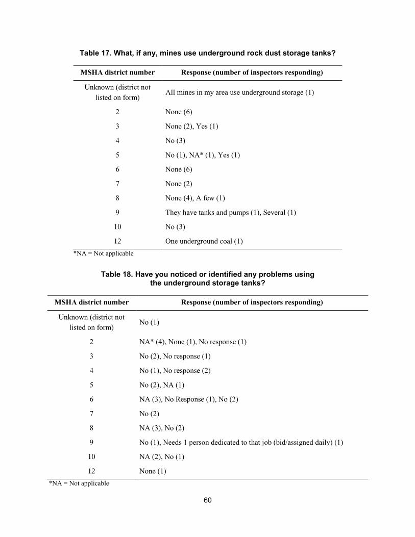
60
Table 17. What, if any, mines use underground rock dust storage tanks?
MSHA district number Response (number of inspectors responding)
Unknown (district not listed on form)
All mines in my area use underground storage (1)
2 None (6)
3 None (2), Yes (1)
4 No (3)
5 No (1), NA* (1), Yes (1)
6 None (6)
7 None (2)
8 None (4), A few (1)
9 They have tanks and pumps (1), Several (1)
10 No (3)
12 One underground coal (1) *NA = Not applicable
Table 18. Have you noticed or identified any problems using the underground storage tanks?
MSHA district number Response (number of inspectors responding)
Unknown (district not listed on form)
No (1)
2 NA* (4), None (1), No response (1)
3 No (2), No response (1)
4 No (1), No response (2)
5 No (2), NA (1)
6 NA (3), No Response (1), No (2)
7 No (2)
8 NA (3), No (2)
9 No (1), Needs 1 person dedicated to that job (bid/assigned daily) (1)
10 NA (2), No (1)
12 None (1) *NA = Not applicable

61
Table 19. Have you noticed color variations in the rock dust being applied at underground operations? If so, explain.
MSHA district number Response (number of inspectors responding)
Unknown (district not listed on form)
No (1)
2 Once, rock dust grayer than usual (1), No (2), Maybe some slight variations (1), Yes – some white/ some gray (1), Yes – after 80% regulation came into effect, rock dust was hard to get and was obtained from other suppliers (1)
3 No, but have heard of gray rock dust (1), Yes – white to gray (1), No (1)
4 Yes, some mines have darker grayish color (1), No (2)
5 No (1), Some is whiter than others (1), Yes – some rock dust is more white (1)
6 Yes (gray) (1), No (2), Yes, from gray to bright white (1), NA* (1), Some appear to be gray in color (1)
7 No (1), Yes – some are more gray (1)
8 No (4), No response (1)
9 Yes (1), Varies - shades of gray (1)
10 No (3)
12 Some dust is darker (1) *NA = Not applicable

62
Table 20. Are continuous miners equipped with scrubbers?
MSHA district number Yes No
Unknown (district not listed on form)
2 -
2 5 1
3 3 -
4 3 1
5 3 1
6 6 -
7 2 -
8 5 -
9 1 1
10 3 -
12 1 -
Table 21. Are the mines you inspect permitted to use scrubbers?
MSHA district number Yes No
Unknown (district not listed on form)
1
2 5 1
3 3
4 2 3
5 3
6 4 4
7 2
8 5
9 2
10 3
12 1 1
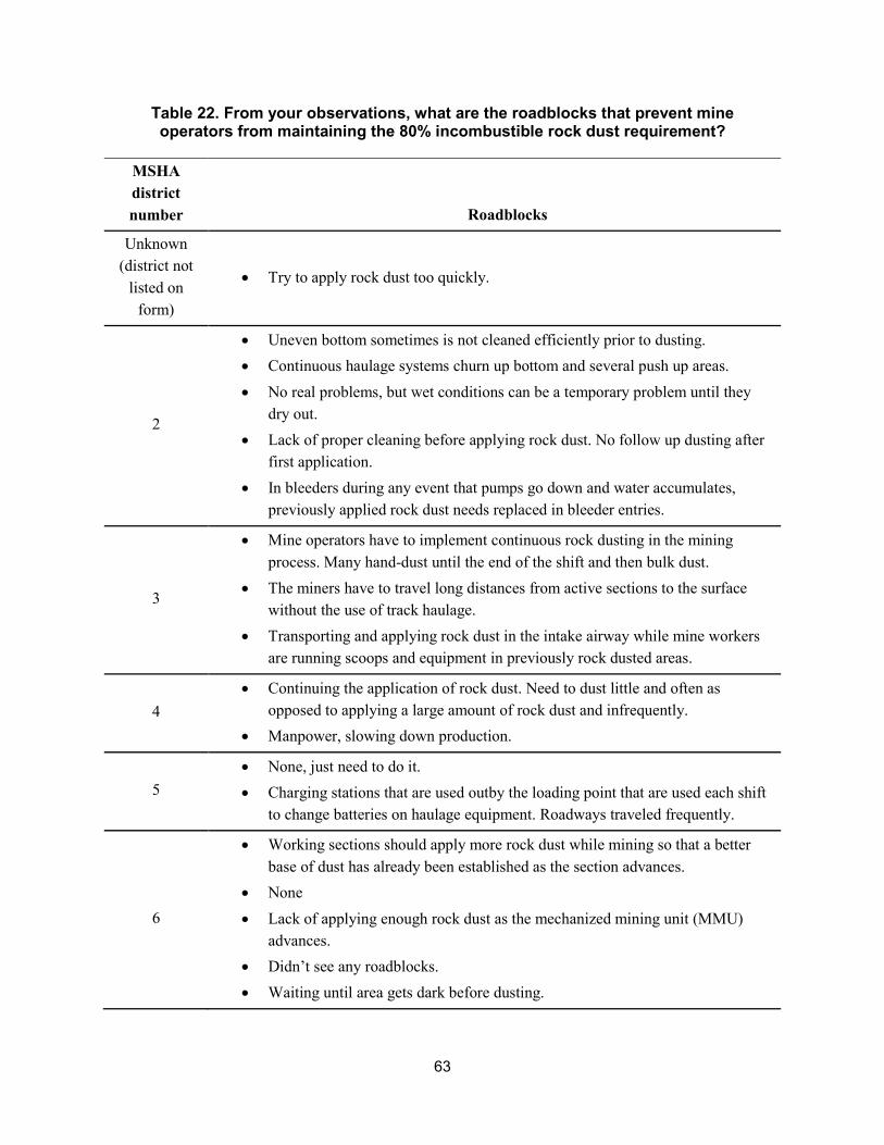
63
Table 22. From your observations, what are the roadblocks that prevent mine operators from maintaining the 80% incombustible rock dust requirement?
MSHA district number Roadblocks
Unknown (district not
listed on form)
• Try to apply rock dust too quickly.
2
• Uneven bottom sometimes is not cleaned efficiently prior to dusting.• Continuous haulage systems churn up bottom and several push up areas.• No real problems, but wet conditions can be a temporary problem until they
dry out.• Lack of proper cleaning before applying rock dust. No follow up dusting after
first application.• In bleeders during any event that pumps go down and water accumulates,
previously applied rock dust needs replaced in bleeder entries.
3
• Mine operators have to implement continuous rock dusting in the miningprocess. Many hand-dust until the end of the shift and then bulk dust.
• The miners have to travel long distances from active sections to the surfacewithout the use of track haulage.
• Transporting and applying rock dust in the intake airway while mine workersare running scoops and equipment in previously rock dusted areas.
4 • Continuing the application of rock dust. Need to dust little and often as
opposed to applying a large amount of rock dust and infrequently.• Manpower, slowing down production.
5 • None, just need to do it.• Charging stations that are used outby the loading point that are used each shift
to change batteries on haulage equipment. Roadways traveled frequently.
6
• Working sections should apply more rock dust while mining so that a betterbase of dust has already been established as the section advances.
• None• Lack of applying enough rock dust as the mechanized mining unit (MMU)
advances.• Didn’t see any roadblocks.• Waiting until area gets dark before dusting.

64
MSHA district number Roadblocks
7
• Mines with rubber tired haulage on a MMU tend to have more “roadway dust”on mine floor if they don’t have a good back scoop program.
• When you count the one inch of bottom, it takes a lot of rock dust. In oldworks it becomes an accessibility issue.
8
• Proper cleaning – the most important step in maintaining incombustiblecontent (IC) happens before rock dust is applied on the section – use ofscrubbers, proper cleanup, and use of belt water sprays.
• Good scooping procedures.• Maintaining a specific rock dusting cycle.
9 • Management, work practices, wet conditions, too much water.• Rock dusting practices.
10
• Lack of good rock dusting practices and poor cleanup prior to dusting.• Traveling through blanket or floor dust by large mobile equipment, diesel
mostly on the unit supply roads; hand dusting on unit while coal beingproduced.
12 • None, all they have to do is make applying the proper amount of rock dust apriority.
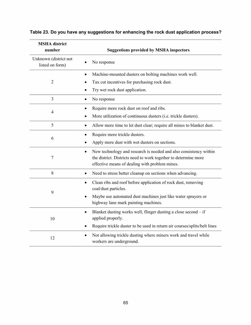
65
Table 23. Do you have any suggestions for enhancing the rock dust application process?
MSHA district number Suggestions provided by MSHA inspectors
Unknown (district not listed on form) • No response
2
• Machine-mounted dusters on bolting machines work well.
• Tax cut incentives for purchasing rock dust.
• Try wet rock dust application.
3 • No response
4 • Require more rock dust on roof and ribs.
• More utilization of continuous dusters (i.e. trickle dusters).
5 • Allow more time to let dust clear; require all mines to blanket dust.
6 • Require more trickle dusters.
• Apply more dust with wet dusters on sections.
7 • New technology and research is needed and also consistency within
the district. Districts need to work together to determine moreeffective means of dealing with problem mines.
8 • Need to stress better cleanup on sections when advancing.
9
• Clean ribs and roof before application of rock dust, removingcoal/dust particles.
• Maybe use automated dust machines just like water sprayers orhighway lane mark painting machines.
10 • Blanket dusting works well, flinger dusting a close second – if
applied properly.
• Require trickle duster to be used in return air courses/splits/belt lines
12 • Not allowing trickle dusting where miners work and travel whileworkers are underground.

66
Miscellaneous comments made by MSHA mine inspectors on various topics:
• Meeting the rock dust particle size requirements. The manufacturer has beencontacted, but it does not appear that the information is coming back to the MSHAinspectors.
• The use of rock dust. One manufacturer’s rock dust, as delivered, was too wet, so mineoperator purchased their own rock dust company.
• Rock dusting on shift. There are reduced visibility and respirable dust issues associatedwith this practice; District 5 has issued citations for reduced visibility related to rockdusting practices.
• The use of scrubbers. Scrubbers do not perform well if the continuous miner is cuttingrock.
• Rock dusting longwall tailgate entries. Continuously dusting tailgate while operatinglongwall; most mines have to stop mining if duster (tailgate) goes down; most mines piperock dust across the face to the tailgate entry.
• Dry coal seams. Requires more rock dust.
• The Blue Creek Seam. Requires a lot of rock dust.
• Water injection. One of the mines injects water into the coal seam after degassing.
• Wet dusting. Wet dusting with dry dust followup does well.
• Pipe lines. One of the mines has rock dust pipe lines and underground tanks; addingpressure points on rock dust lines to increase pressure should be considered to move dust.
• The use of rock dust barriers or bags. There is some interest in using bags filled withrock dust to stop or reduce the effect of an explosion, but only one operation is trying it.There is some interest in “Walls of Water” for suppressing an explosion.
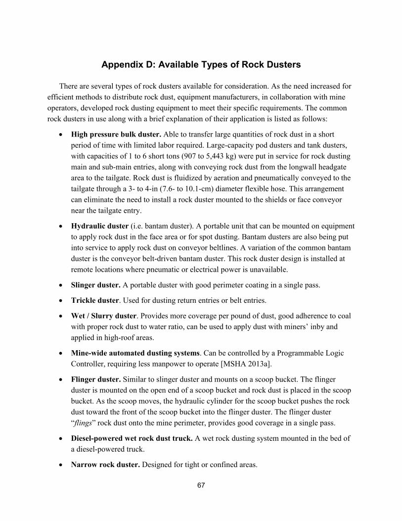
67
Appendix D: Available Types of Rock Dusters
There are several types of rock dusters available for consideration. As the need increased for efficient methods to distribute rock dust, equipment manufacturers, in collaboration with mine operators, developed rock dusting equipment to meet their specific requirements. The common rock dusters in use along with a brief explanation of their application is listed as follows:
• High pressure bulk duster. Able to transfer large quantities of rock dust in a short period of time with limited labor required. Large-capacity pod dusters and tank dusters, with capacities of 1 to 6 short tons (907 to 5,443 kg) were put in service for rock dusting main and sub-main entries, along with conveying rock dust from the longwall headgate area to the tailgate. Rock dust is fluidized by aeration and pneumatically conveyed to the tailgate through a 3- to 4-in (7.6- to 10.1-cm) diameter flexible hose. This arrangement can eliminate the need to install a rock duster mounted to the shields or face conveyor near the tailgate entry.
• Hydraulic duster (i.e. bantam duster). A portable unit that can be mounted on equipmentto apply rock dust in the face area or for spot dusting. Bantam dusters are also being putinto service to apply rock dust on conveyor beltlines. A variation of the common bantamduster is the conveyor belt-driven bantam duster. This rock duster design is installed atremote locations where pneumatic or electrical power is unavailable.
• Slinger duster. A portable duster with good perimeter coating in a single pass.
• Trickle duster. Used for dusting return entries or belt entries.
• Wet / Slurry duster. Provides more coverage per pound of dust, good adherence to coalwith proper rock dust to water ratio, can be used to apply dust with miners’ inby andapplied in high-roof areas.
• Mine-wide automated dusting systems. Can be controlled by a Programmable LogicController, requiring less manpower to operate [MSHA 2013a].
• Flinger duster. Similar to slinger duster and mounts on a scoop bucket. The flingerduster is mounted on the open end of a scoop bucket and rock dust is placed in the scoopbucket. As the scoop moves, the hydraulic cylinder for the scoop bucket pushes the rockdust toward the front of the scoop bucket into the flinger duster. The flinger duster“flings” rock dust onto the mine perimeter, provides good coverage in a single pass.
• Diesel-powered wet rock dust truck. A wet rock dusting system mounted in the bed ofa diesel-powered truck.
• Narrow rock duster. Designed for tight or confined areas.

68
• Pneumatic rock dust “puffer.” Discharges a “puff” of rock dust at a preset time interval,used on conveyor belt lines.
• Combination mobile fan / rock duster. Electric powered, discharges rock dust into thestream of return air generated at the coal mine face.
A list of approved rock dusters is available on the MSHA website: (www.msha.gov/techsupp/acc/lists/18rdust.pdf).
69
Appendix E: Rock Dust Receiving, Storage, and Distribution
Rock dust is shipped directly to the mine site from the manufacturer or purchased from a distributor. It is common practice for a mine operator to have more than one supplier. Bagged rock dust is delivered on pallets and wrapped to prevent moisture from entering the rock dust. An increase in rock dust moisture level can negatively impact its ability to disperse in adequate quantities required to inert a propagating coal dust explosion. As the moisture level increases, the rock dust particles agglomerate. The resulting larger particles are heavier, making them more difficult to disperse. Rock dust manufacturers contacted by NIOSH indicated variations in the percent of moisture in the rock dust when it leaves the plant. Moisture values of 0.1% to 0.5% are common [Anstine 2013; Cooper 2013].
Rock dust is normally received at the mine site in one or more of the following forms:
• Bulk rock dust. Weight of shipment depends on storage capacity at the mine site. Bulkrock dust is delivered to the mine site by truck or other transport suitable for offloadingthe material into a storage silo located on the surface. The silo is commonly located overthe underground workings, accessible by truck for unloading rock dust, and electricallypowered to control flow of dust from the surface tank to the underground workings. Rockdust remains in the silo until needed underground. When the silo dispenses rock dust, itflows from the silo through a vertical pipe to the underground workings. Depending onthe arrangement at the receiving end, rock dust can be placed directly in a vehicle thatwill be used to disperse the rock dust or placed in a rock dust storage bin to be dispersedas needed.
• Rock dust shipped in reinforced bags. 1,000- to 3,000-lb capacity per bag. Reinforcedbags (i.e. super sacks) provide a safe and efficient method to offload rock dust directlyinto a scoop bucket or coal hauler. The bags are designed to prevent moisture fromgetting to the rock dust. When needed, a reinforced bag is hung from a hook installed inthe mine roof. The bag must be at a sufficient elevation to allow a mine scoop or similarmachine to maneuver under the bag. Once in position, the drawstring on the bottom ofthe bag is loosened which allows the rock dust to flow from the bag into the rock dusterthat will distribute the rock dust. When the bag is empty, it is removed from the mine.This method of unloading rock dust is less labor intensive than unloading 40- to 60-lbbagged rock dust. Unless the reinforced bag is damaged, it can be returned to the vendorfor refilling.
• Rock dust enclosed in double strength paper bags, 40- to 60-lb capacity per bag.Bags of this size are routinely received by truck on shrink-wrapped pallets to reduce thelikelihood of moisture exposure to the rock dust. Upon receipt, the bags are stored in a

70
dry area either on the surface or underground. The bags are used for filling hoppers on bantam dusters, wet rock dusters, spot or maintenance dusting in the face area, and other dusting applications. In low seam applications, bags of this size serve as the primary means of supplying rock dust to the entire underground mine. The larger or high-capacity bags have limited use in low coal seams due to the height restrictions. At some mines, it may be possible to load the scoop from the larger bags on the surface, then transport the rock dust underground. However, rock dust has a tendency to compact as you travel into the mine making it difficult to unload.
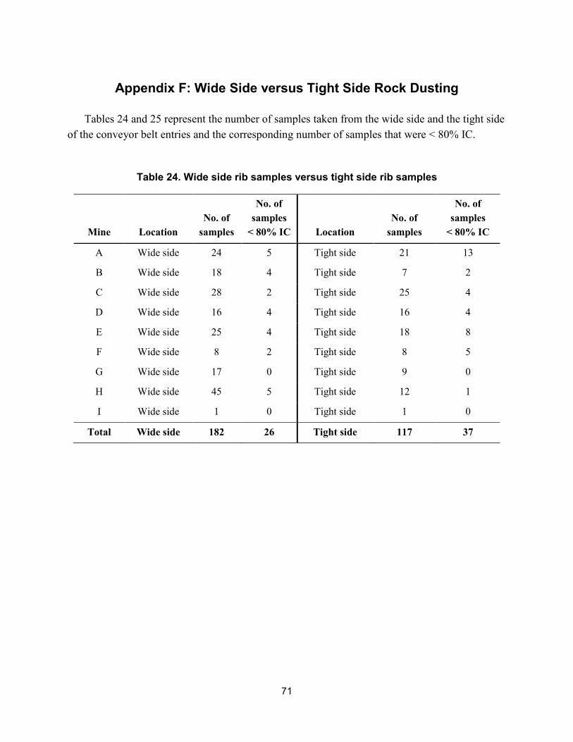
71
Appendix F: Wide Side versus Tight Side Rock Dusting
Tables 24 and 25 represent the number of samples taken from the wide side and the tight side of the conveyor belt entries and the corresponding number of samples that were < 80% IC.
Table 24. Wide side rib samples versus tight side rib samples
Mine Location No. of
samples
No. of samples
< 80% IC Location No. of
samples
No. of samples
< 80% IC
A Wide side 24 5 Tight side 21 13
B Wide side 18 4 Tight side 7 2
C Wide side 28 2 Tight side 25 4
D Wide side 16 4 Tight side 16 4
E Wide side 25 4 Tight side 18 8
F Wide side 8 2 Tight side 8 5
G Wide side 17 0 Tight side 9 0
H Wide side 45 5 Tight side 12 1
I Wide side 1 0 Tight side 1 0
Total Wide side 182 26 Tight side 117 37
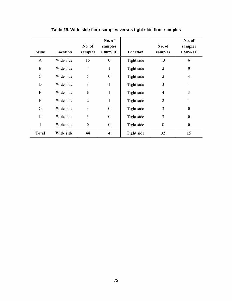
72
Table 25. Wide side floor samples versus tight side floor samples
Mine Location No. of
samples
No. of samples
< 80% IC Location No. of
samples
No. of samples
< 80% IC
A Wide side 15 0 Tight side 13 6
B Wide side 4 1 Tight side 2 0
C Wide side 5 0 Tight side 2 4
D Wide side 3 1 Tight side 3 1
E Wide side 6 1 Tight side 4 3
F Wide side 2 1 Tight side 2 1
G Wide side 4 0 Tight side 3 0
H Wide side 5 0 Tight side 3 0
I Wide side 0 0 Tight side 0 0
Total Wide side 44 4 Tight side 32 15
73
Appendix G: Wet Rock Dusting
The term wet rock dusting refers to the process of applying rock dust in a slurry form to the ribs and roof surfaces of a coal mine. MSHA’s Program Policy Manual, Volume V, Coal Mines Subpart E, 75.403 allows limestone or marble rock dust meeting the specifications of 30 CFR 75.2 to be applied wet. Foam rock dusting is included in this policy as well. However, wet rock dusting is limited to the rib and roof surfaces in the face areas only and must be applied at a coverage rate of not less than 3 oz/ft2, while keeping the mixture of water to dust not more than 6–8 gal per 100 lb of rock dust. The requirement for a coverage rate of at least 3 oz/ft2 ensures that the rock dust mixture is not too fluid so that sufficient rock dust adheres to the mine surfaces. Wet rock dusting the ribs and roof at the face area does not eliminate the necessity for dry rock dusting the floor. The wet rock dust coats the rib and roof surfaces, encapsulates accumulations of freshly generated float coal dust, and increases visibility at the face area when applied. After the wet rock dust dries, dry rock dust must still be applied to all surfaces over the wet rock dusted area to ensure that a dispersible rock dust is present. The main benefit of wet rock dusting is that it can occur without stopping coal production, whereas mechanically applied dry rock dust requires the withdrawal of miners because of the increased dust suspension, which significantly reduces visibility and contributes to the miners’ total nuisance dust exposure.
There are some data from the Bruceton Experimental Mine (BEM) explosion research conducted in the 1950s by the Bureau of Mines that compared wet rock dust applications to dry rock dust [USBM 1956b]. In testing, once the wet dust dried and formed a cake, it was not effective in preventing coal dust explosion propagation. Explosion suppression was achieved in some experiments if dry rock dust was subsequently distributed over the area. In these experiments, dispersibility was a key controlling factor in the explosion suppression.
Wet rock dusting application studies were conducted recently by NIOSH researchers in the Safety Research Coal Mine (SRCM) and in a West Virginia operating mine. For the wet rock dusting application trials within the SRCM, two areas were prepared for application of two types of rock dust—a marble rock dust (Rock Dust A) and a limestone rock dust (Rock Dust B). The two areas within the SRCM represented: (1) short-term wet conditions on coal and (2) long-term wet conditions on coal. Preparation included removing, through the use of a water hose with nozzle, any existing rock dust and loose coal from the roof and ribs in each evaluation area. Figure 12 is the mine map showing the locations of each of the evaluation areas. Temperature and relative humidity data loggers were installed at each location and at the mine portal. Samples of each dust were collected and sealed in plastic bags on a regular basis to monitor the in situ rate of drying.
Area 1 is in the dead-ended 14-Room off C-Butt within the SRCM (green area on mine map in Figure 12). The area is wet in the summer and typically dries out in the winter months. Some
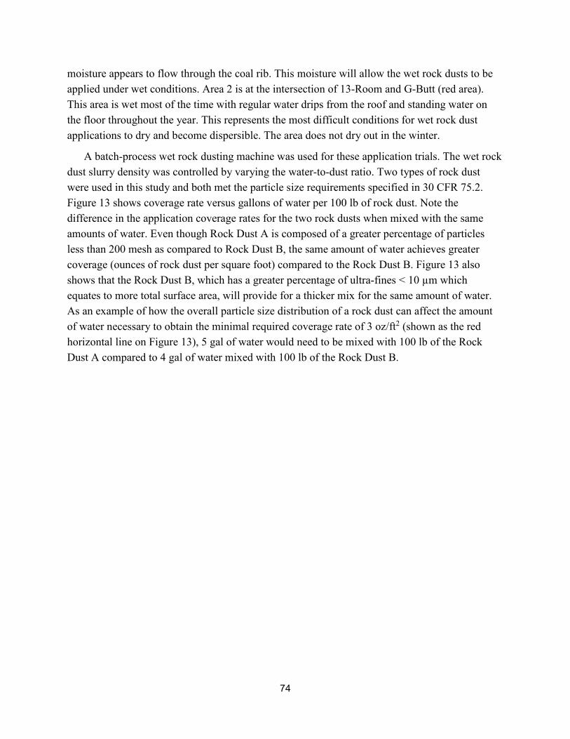
74
moisture appears to flow through the coal rib. This moisture will allow the wet rock dusts to be applied under wet conditions. Area 2 is at the intersection of 13-Room and G-Butt (red area). This area is wet most of the time with regular water drips from the roof and standing water on the floor throughout the year. This represents the most difficult conditions for wet rock dust applications to dry and become dispersible. The area does not dry out in the winter.
A batch-process wet rock dusting machine was used for these application trials. The wet rock dust slurry density was controlled by varying the water-to-dust ratio. Two types of rock dust were used in this study and both met the particle size requirements specified in 30 CFR 75.2. Figure 13 shows coverage rate versus gallons of water per 100 lb of rock dust. Note the difference in the application coverage rates for the two rock dusts when mixed with the same amounts of water. Even though Rock Dust A is composed of a greater percentage of particles less than 200 mesh as compared to Rock Dust B, the same amount of water achieves greater coverage (ounces of rock dust per square foot) compared to the Rock Dust B. Figure 13 also shows that the Rock Dust B, which has a greater percentage of ultra-fines < 10 µm which equates to more total surface area, will provide for a thicker mix for the same amount of water. As an example of how the overall particle size distribution of a rock dust can affect the amount of water necessary to obtain the minimal required coverage rate of 3 oz/ft2 (shown as the red horizontal line on Figure 13), 5 gal of water would need to be mixed with 100 lb of the Rock Dust A compared to 4 gal of water mixed with 100 lb of the Rock Dust B.
75
Figure 13. Ounces of dry rock dust per square foot with respect to the wet rock dust slurry mix.
0
2
4
6
8
10
12
14
0 1 2 3 4 5 6 7 8
Rock Dust, oz/ft2
Water gal/100 lb Rock Dust
Rock dust A
Rock dust B
Minimal coverage = 3 oz/ft2
Table 26 lists the sequence of tests conducted over the one-day application period. The wet rock dust was applied in the C-14 and G-13 areas (Figure 12) at the rate typically used in mines (7 gal of water per 100 lb of rock dust). This mix was observed to be very thin and did not accumulate into a thick layer. It appeared more like whitewash paint and most of the dust component ran off onto the floor. Additional applications were then conducted using 4 and 3 gal of water per 100 lb of rock dust.
Samples of the wet rock dust, scraped from the ribs, were taken for moisture analyses each day for one week, one week later, and three months later. Some sample locations were discontinued because sufficient material was not available. Samples were collected in the mine, transported in sealed plastic bags, and processed by NIOSH researchers by weighing each wet sample on the day of sampling, drying overnight in an oven at 90°C to drive off the moisture, and reweighing the next day. All of the wet rock dusting applications within the G-13 test area remained very wet with little change in moisture over the entire study period. A few of the samples in the C-14 area showed a modest drop in their moisture content over the first two
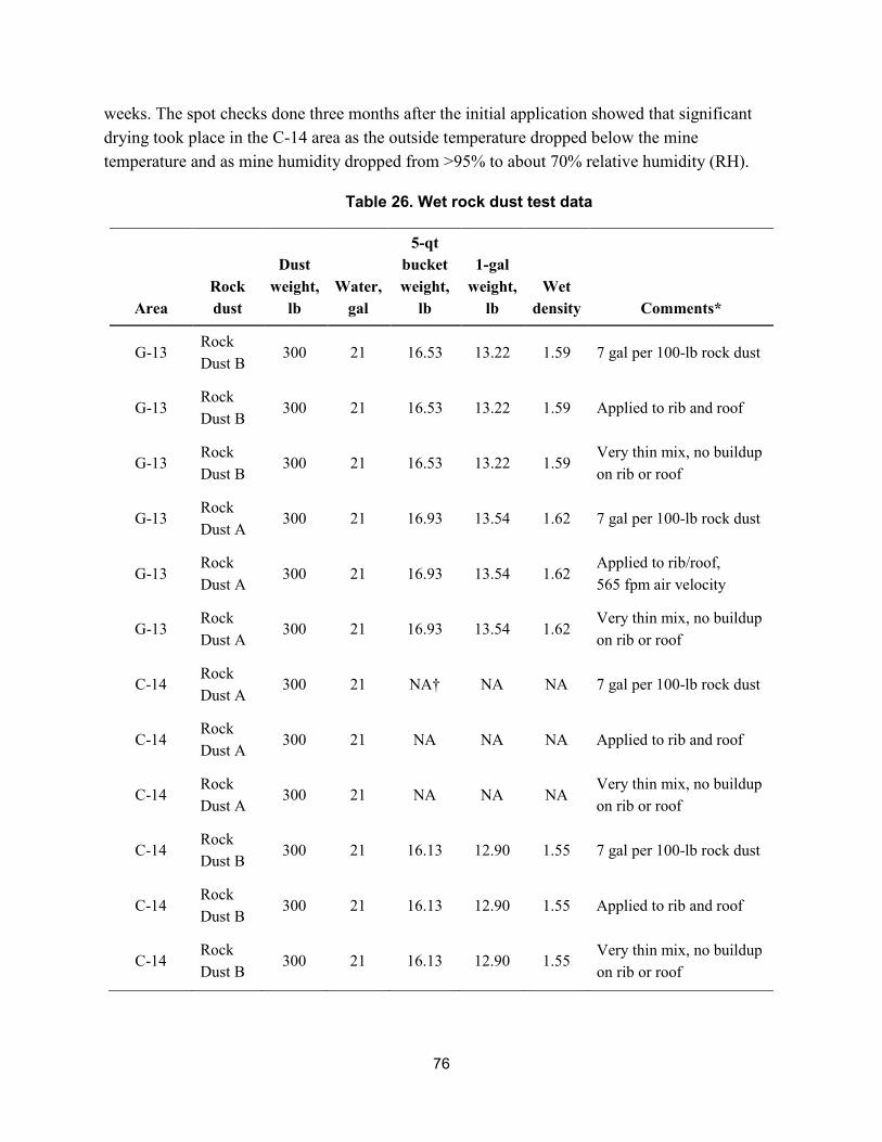
76
weeks. The spot checks done three months after the initial application showed that significant drying took place in the C-14 area as the outside temperature dropped below the mine temperature and as mine humidity dropped from >95% to about 70% relative humidity (RH).
Table 26. Wet rock dust test data
Area Rock dust
Dust weight,
lb Water,
gal
5-qt bucket weight,
lb
1-gal weight,
lb Wet
density Comments*
G-13 Rock Dust B
300 21 16.53 13.22 1.59 7 gal per 100-lb rock dust
G-13 Rock Dust B
300 21 16.53 13.22 1.59 Applied to rib and roof
G-13 Rock Dust B
300 21 16.53 13.22 1.59 Very thin mix, no buildup on rib or roof
G-13 Rock Dust A
300 21 16.93 13.54 1.62 7 gal per 100-lb rock dust
G-13 Rock Dust A
300 21 16.93 13.54 1.62 Applied to rib/roof, 565 fpm air velocity
G-13 Rock Dust A
300 21 16.93 13.54 1.62 Very thin mix, no buildup on rib or roof
C-14 Rock Dust A
300 21 NA† NA NA 7 gal per 100-lb rock dust
C-14 Rock Dust A
300 21 NA NA NA Applied to rib and roof
C-14 Rock Dust A
300 21 NA NA NA Very thin mix, no buildup on rib or roof
C-14 Rock Dust B
300 21 16.13 12.90 1.55 7 gal per 100-lb rock dust
C-14 Rock Dust B
300 21 16.13 12.90 1.55 Applied to rib and roof
C-14 Rock Dust B
300 21 16.13 12.90 1.55 Very thin mix, no buildup on rib or roof
77
Area Rock dust
Dust weight,
lb Water,
gal
5-qt bucket weight,
lb
1-gal weight,
lb Wet
density Comments*
C-14–15 Rock Dust A
300 12 NA NA NA 4 gal per 100-lb rock dust
C-14–15 Rock Dust A
50 0 NA NA NA
After using ½ of the above mix, another rock dust bag was added to the mix to get ~ 3 gal per 100-lb rock dust, very thick. Applied to rib.
C-14–15 Rock Dust B
400 16 NA NA NA 4 gal per 100-lb rock dust
C-14–15 Rock Dust B
400 16 NA NA NA Applied to rib and roof
*Compressor air supply at 40 psi for each test.†NA – Not applicable because sample was not collected or recorded.
Table 27 lists the recorded data of the wet rock dust coverage rate on the coal mine ribs. This data was obtained using a 6 in x 6 in frame to control a small area where the wet rock dust applications were washed off the mine surface (rib) into a plastic sample bag. The wet samples were then dried and weighed. The weight of each sample divided by the washed area for that sample provided a data point for the ounces per square ft of mine entry covered by the wet rock dusting application. The locations where the rate is greater than 3 oz/ft2 are shown in bold text, and those less than 3 oz/ft2 are shown in italics. Wet rock dust samples from the mine roof were not collected in either of the test areas.
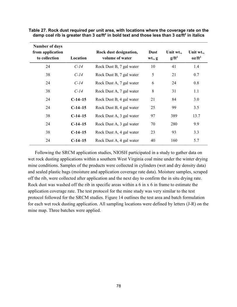
78
Table 27. Rock dust required per unit area, with locations where the coverage rate on the damp coal rib is greater than 3 oz/ft2 in bold text and those less than 3 oz/ft2 in italics
Number of days from application
to collection Location Rock dust designation,
volume of water Dust wt., g
Unit wt., g/ft2
Unit wt., oz/ft2
24 C-14 Rock Dust B, 7 gal water 10 41 1.4
38 C-14 Rock Dust B, 7 gal water 5 21 0.7
24 C-14 Rock Dust A, 7 gal water 6 24 0.8
38 C-14 Rock Dust A, 7 gal water 8 31 1.1
24 C-14–15 Rock Dust B, 4 gal water 21 84 3.0
24 C-14–15 Rock Dust B, 4 gal water 25 99 3.5
38 C-14–15 Rock Dust A, 3 gal water 97 389 13.7
24 C-14–15 Rock Dust A, 3 gal water 70 280 9.9
38 C-14–15 Rock Dust A, 4 gal water 23 93 3.3
24 C-14–15 Rock Dust A, 4 gal water 40 160 5.7
Following the SRCM application studies, NIOSH participated in a study to gather data on wet rock dusting applications within a southern West Virginia coal mine under the winter drying mine conditions. Samples of the products were collected in cylinders (wet and dry density data) and sealed plastic bags (moisture and application coverage rate data). Moisture samples, scraped off the rib, were collected after application and the next day to confirm the in situ drying rate. Rock dust was washed off the rib in specific areas within a 6 in x 6 in frame to estimate the application coverage rate. The test protocol for the mine study was very similar to the test protocol followed for the SRCM studies. Figure 14 outlines the test area and batch formulation for each wet rock dusting application. All sampling locations were defined by letters (J-R) on the mine map. Three batches were applied.
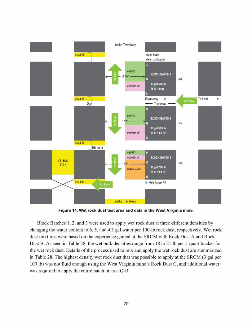
79
Figure 14. Wet rock dust test area and data in the West Virginia mine.
Block Batches 1, 2, and 3 were used to apply wet rock dust at three different densities by changing the water content to 6, 5, and 4.3 gal water per 100-lb rock dust, respectively. Wet rock dust mixtures were based on the experience gained at the SRCM with Rock Dust A and Rock Dust B. As seen in Table 28, the wet bulk densities range from 18 to 21 lb per 5-quart bucket for the wet rock dust. Details of the process used to mix and apply the wet rock dust are summarized in Table 28. The highest density wet rock dust that was possible to apply at the SRCM (3 gal per 100 lb) was not fluid enough using the West Virginia mine’s Rock Dust C, and additional water was required to apply the entire batch in area Q-R.
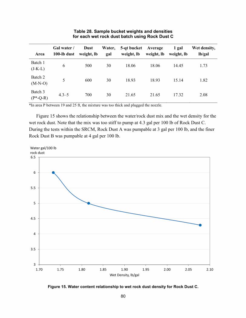
80
Table 28. Sample bucket weights and densities for each wet rock dust batch using Rock Dust C
Area Gal water / 100-lb dust
Dust weight, lb
Water, gal
5-qt bucket weight, lb
Average weight, lb
1 gal weight, lb
Wet density, lb/gal
Batch 1 (J-K-L)
6 500 30 18.06 18.06 14.45 1.73
Batch 2 (M-N-O)
5 600 30 18.93 18.93 15.14 1.82
Batch 3 (P*-Q-R)
4.3–5 700 30 21.65 21.65 17.32 2.08
*In area P between 19 and 25 ft, the mixture was too thick and plugged the nozzle.
Figure 15 shows the relationship between the water/rock dust mix and the wet density for the wet rock dust. Note that the mix was too stiff to pump at 4.3 gal per 100 lb of Rock Dust C. During the tests within the SRCM, Rock Dust A was pumpable at 3 gal per 100 lb, and the finer Rock Dust B was pumpable at 4 gal per 100 lb.
Figure 15. Water content relationship to wet rock dust density for Rock Dust C.
3
3.5
4
4.5
5
5.5
6
6.5
1.70 1.75 1.80 1.85 1.90 1.95 2.00 2.05 2.10
Water gal/100 lb rock dust
Wet Density, lb/gal
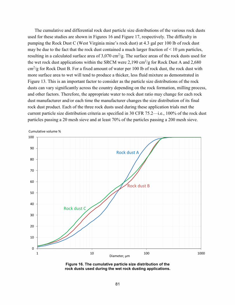
81
The cumulative and differential rock dust particle size distributions of the various rock dusts used for these studies are shown in Figures 16 and Figure 17, respectively. The difficulty in pumping the Rock Dust C (West Virginia mine’s rock dust) at 4.3 gal per 100 lb of rock dust may be due to the fact that the rock dust contained a much larger fraction of < 10 µm particles, resulting in a calculated surface area of 3,070 cm2/g. The surface areas of the rock dusts used for the wet rock dust applications within the SRCM were 2,190 cm2/g for Rock Dust A and 2,680 cm2/g for Rock Dust B. For a fixed amount of water per 100 lb of rock dust, the rock dust with more surface area to wet will tend to produce a thicker, less fluid mixture as demonstrated in Figure 13. This is an important factor to consider as the particle size distributions of the rock dusts can vary significantly across the country depending on the rock formation, milling process, and other factors. Therefore, the appropriate water to rock dust ratio may change for each rock dust manufacturer and/or each time the manufacturer changes the size distribution of its final rock dust product. Each of the three rock dusts used during these application trials met the current particle size distribution criteria as specified in 30 CFR 75.2—i.e., 100% of the rock dust particles passing a 20 mesh sieve and at least 70% of the particles passing a 200 mesh sieve.
Figure 16. The cumulative particle size distribution of the rock dusts used during the wet rock dusting applications.
0
10
20
30
40
50
60
70
80
90
100
1 10 100 1000
Cumulative volume %
Diameter, µm
Rock dust A
Rock dust B
Rock dust C
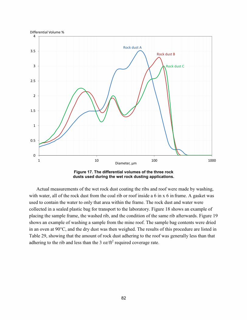
82
Figure 17. The differential volumes of the three rock dusts used during the wet rock dusting applications.
0
0.5
1
1.5
2
2.5
3
3.5
4
1 10 100 1000
Differential Volume %
Diameter, µm
Rock dust A
Rock dust B
Rock dust C
Actual measurements of the wet rock dust coating the ribs and roof were made by washing, with water, all of the rock dust from the coal rib or roof inside a 6 in x 6 in frame. A gasket was used to contain the water to only that area within the frame. The rock dust and water were collected in a sealed plastic bag for transport to the laboratory. Figure 18 shows an example of placing the sample frame, the washed rib, and the condition of the same rib afterwards. Figure 19 shows an example of washing a sample from the mine roof. The sample bag contents were dried in an oven at 90°C, and the dry dust was then weighed. The results of this procedure are listed in Table 29, showing that the amount of rock dust adhering to the roof was generally less than that adhering to the rib and less than the 3 oz/ft2 required coverage rate.
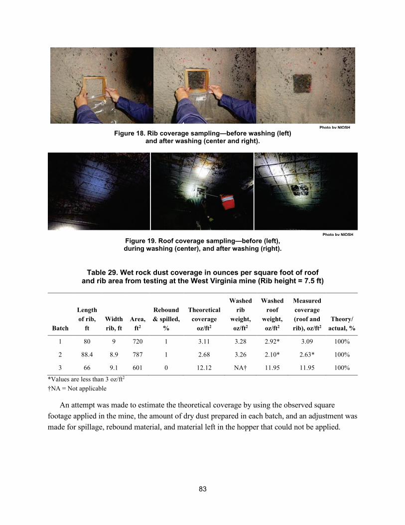
83
Figure 18. Rib coverage sampling—before washing (left) and after washing (center and right).
Figure 19. Roof coverage sampling—before (left), during washing (center), and after washing (right).
Table 29. Wet rock dust coverage in ounces per square foot of roof and rib area from testing at the West Virginia mine (Rib height = 7.5 ft)
Batch
Length of rib,
ft Width rib, ft
Area, ft2
Rebound & spilled,
%
Theoretical coverage
oz/ft2
Washed rib
weight, oz/ft2
Washed roof
weight, oz/ft2
Measured coverage (roof and rib), oz/ft2
Theory/ actual, %
1 80 9 720 1 3.11 3.28 2.92* 3.09 100%
2 88.4 8.9 787 1 2.68 3.26 2.10* 2.63* 100%
3 66 9.1 601 0 12.12 NA† 11.95 11.95 100%
*Values are less than 3 oz/ft2
†NA = Not applicable
An attempt was made to estimate the theoretical coverage by using the observed square footage applied in the mine, the amount of dry dust prepared in each batch, and an adjustment was made for spillage, rebound material, and material left in the hopper that could not be applied.
Photo by NIOSH
Photo by NIOSH
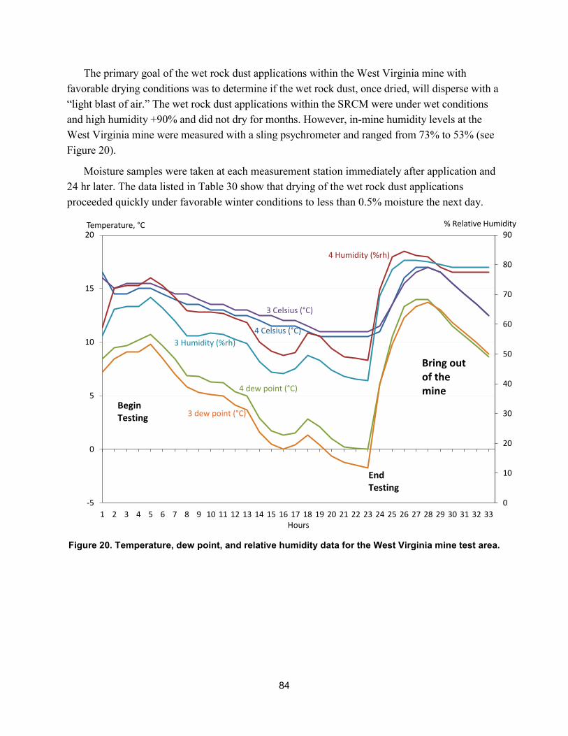
84
The primary goal of the wet rock dust applications within the West Virginia mine with favorable drying conditions was to determine if the wet rock dust, once dried, will disperse with a “light blast of air.” The wet rock dust applications within the SRCM were under wet conditions and high humidity +90% and did not dry for months. However, in-mine humidity levels at the West Virginia mine were measured with a sling psychrometer and ranged from 73% to 53% (see Figure 20).
Moisture samples were taken at each measurement station immediately after application and 24 hr later. The data listed in Table 30 show that drying of the wet rock dust applications proceeded quickly under favorable winter conditions to less than 0.5% moisture the next day.
Figure 20. Temperature, dew point, and relative humidity data for the West Virginia mine test area.
0
10
20
30
40
50
60
70
80
90
-5
0
5
10
15
20
1 2 3 4 5 6 7 8 9 10 11 12 13 14 15 16 17 18 19 20 21 22 23 24 25 26 27 28 29 30 31 32 33
% Relative HumidityTemperature, °C
Hours
Begin Testing
End Testing
Bring out of the mine
4 Celsius (°C)
3 Celsius (°C)
4 Humidity (%rh)
3 Humidity (%rh)
4 dew point (°C)
3 dew point (°C)
85
Table 30. Wet rock dust moisture change over 24 hr. Note: Dry dust was collected by using a 1-in wide bristle brush inside the 6-in x 6-in tray. The "w/air" designates the
stations where 50-psi compressed air was used to aid in the application.
Type Measurement
station
Initial moisture,
%
24-hour moisture,
%
Initial average
moisture, %
24-hour average
moisture, %
Batch 1 (6 gal)
J 16.3 0.3 15.5 0.3
Batch 1 (6 gal)
K 16.9 15.5 0.3
Batch 1 (6 gal)
K w/air 16.1 15.5 0.3
Batch 1 (6 gal)
L w/air 12.6 0.3 15.5 0.3
Batch 2 (5 gal)
M w/air 16.7 0.3 16.2 0.2
Batch 2 (5 gal)
N 15.4 16.2 0.2
Batch 2 (5 gal)
O 16.6 0.2 16.2 0.2
Batch 3 (4.3 gal)
P 16.9 17.3 2.8
Batch 3 (4.3 gal)
Q w/air 17.7 17.3 2.8
Batch 3 (4.3 gal)
Q 5.3 17.3 2.8
Batch 3 (4.3 gal)
R (5-gal mix) 0.2 17.3 2.8
In addition to the sample bucket weights, 3-in-diameter x 6-in-high cylinders were filled at each measurement station. The 5-quart sample bucket was filled from the 5-gal collection bucket. After the sample bucket was weighed, the cylinders were filled. Table 31 shows the bucket and cylinder densities for the wet rock dust.
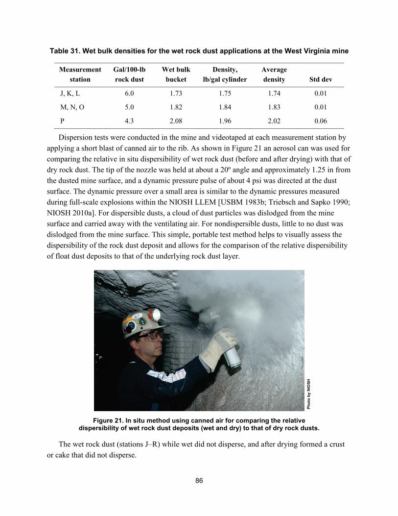
86
Table 31. Wet bulk densities for the wet rock dust applications at the West Virginia mine
Measurement station
Gal/100-lb rock dust
Wet bulk bucket
Density, lb/gal cylinder
Average density Std dev
J, K, L 6.0 1.73 1.75 1.74 0.01
M, N, O 5.0 1.82 1.84 1.83 0.01
P 4.3 2.08 1.96 2.02 0.06
Dispersion tests were conducted in the mine and videotaped at each measurement station by applying a short blast of canned air to the rib. As shown in Figure 21 an aerosol can was used for comparing the relative in situ dispersibility of wet rock dust (before and after drying) with that of dry rock dust. The tip of the nozzle was held at about a 20º angle and approximately 1.25 in from the dusted mine surface, and a dynamic pressure pulse of about 4 psi was directed at the dust surface. The dynamic pressure over a small area is similar to the dynamic pressures measured during full-scale explosions within the NIOSH LLEM [USBM 1983b; Triebsch and Sapko 1990; NIOSH 2010a]. For dispersible dusts, a cloud of dust particles was dislodged from the mine surface and carried away with the ventilating air. For nondispersible dusts, little to no dust was dislodged from the mine surface. This simple, portable test method helps to visually assess the dispersibility of the rock dust deposit and allows for the comparison of the relative dispersibility of float dust deposits to that of the underlying rock dust layer.
Figure 21. In situ method using canned air for comparing the relative dispersibility of wet rock dust deposits (wet and dry) to that of dry rock dusts.
The wet rock dust (stations J–R) while wet did not disperse, and after drying formed a crust or cake that did not disperse.
Phot
o by
NIO
SH
Delivering on the Nation’s promise: safety and health at work for all people through research and prevention
To receive NIOSH documents or more information about occupational safety and health topics, please contact NIOSH:
Telephone: 1-800-CDC-INFO (1-800-232-4636)
TTY: 1-888-232-6348
CDC INFO: www.cdc.gov/info or visit the NIOSH website at www.cdc.gov/niosh For a monthly update on news at NIOSH, subscribe to NIOSH eNews by visiting www.cdc.gov/niosh/eNews.
DHHS (NIOSH) Publication No. 2017–101